Tele Radio C1406A RF Module User Manual IM TG2 RX002 A10 EN
Tele Radio AB RF Module IM TG2 RX002 A10 EN
User Manual
TG-T14-4,TG-T14-5,TG-T14-6,TG-T14-7,TG-T14-8,TG-T14-9,
TG-T15-4,TG-T15-5,TG-T15-6,TG-T15-7,TG-T15-8,TG-T15-9
TG-R4-26(TG-RX-MNLCAN),TG-R4-28(TG-RX-MNRCAN),TG-R4-30(TG-RX-MNPCAN),TG-R4-41(TG-RX-
MNLJ1939),TG-R4-43(TG-RX-MNRJ1939),TG-R4-45(TG-RX-MNPJ1939,TG-R4-36(TG-RX-MNLANA),
TG-R4-38(TG-RX-MNRANA),TG-R4-40(TG-RX-MNPANA)
LANGUAGE:English(original)
IM-TG2-RX009-CERT
Installation instructions

CONTENTS
Chapter 1: CUSTOMER INFORMATION 3
Chapter 2: SAFETY INFORMATION 5
Chapter 3: PRODUCT PAGES 7
TG-RX-MNLANA, TG-RX-MNRANA, TG-RX-MNPANA base board receiver with an expan-
sion board 8
TG-RX-MNLCAN, TG-RX-MNRCAN, TG-RX-MNPCAN, TG-RX-MNLJ1939, TG-RX-
MNRJ1939, TG-RX-MNPJ1939 base board receiver with CAN expansion board 17
TG-T14-4, TG-T14-5, TG-T14-6, TG-T14-7, TG-T14-8, TG-T14-9, TG-T15-4, TG-T15-5,
TG-T15-6, TG-T15-7, TG-T15-8, TG-T15-9 transmitter 25
Chapter 4: INSTALLERS GUIDE 30
Navigate in menu mode 30
Enable PINcodes 30
Create PIN codes 31
Erase PIN codes 32
Show registered PIN codes 32
Start the transmitter in operating mode 33
Start the transmitter in operating mode with PIN codes 34
Turn the transmitter off 34
Login/logout 35
Register 36
Erase 37
Replace 38
Automatic shutdown 39
Frequencies & channels 40
Relay functionality 43
Digital inputs 44
Chapter 5: OPERATING MODES 45
Chapter 6: LOAD SELECT MODES 46
Chapter 7: BATTERY GUIDE 51
Chapter 8: CERTIFICATIONS CHAPTER 55
FCC/ IC 55
EC/EEA declaration of conformity 61
-2-

Chapter 1: CUSTOMER INFORMATION
CHAPTER 1: CUSTOMER INFORMATION
THANKYOUFORPURCHASINGATELERADIOABPRODUCT
READALLINSTRUCTIONS ANDWARNINGS CAREFULLY BEFOREMOUNTING, INSTALLING
ANDCONFIGURATING THEPRODUCTS.
These instructions are published by Tele Radio AB without any guarantee. The instructions may be
removed or revised by Tele Radio AB at any time and without further notice. Corrections and additions
will be added to the latest version of the instruction.
IMPORTANT! These instructions are directed to installers. There are separate instructions directed
towards end users. The instructions that contain information on the installation and configuration of the
radio remote control unit on the machine are not intended to be passed on to the end user. Only such
information may be passed on to the end user that is needed to operate the machine correctly by radio
remote control.
Tele Radio AB products are covered by a guarantee/ warranty against material, construction or
manufacturing faults. During the guarantee/ warranty period, Tele Radio AB may replace the product or
faulty parts with new. Work under guarantee/ warranty must be carried out by Tele Radio AB or by an
authorized service center specified by Tele Radio AB. Contact your Tele Radio AB representative if you
need support or service.
©Tele Radio AB
Datavägen 21
SE-436 36 ASKIM
SWEDEN
Tel: +46-31-748 54 60
Fax: +46-31-68 54 64
www.tele-radio.com
-3-

WARNINGS&RESTRICTIONS
WARNING! Tele Radio remote controls are often built into wider applications. We recommend that
the system is provided with a wired emergency stop where necessary.
NOTE! We recommend that the functionality of the STOP button is being tested at a regular basis: At a
minimum, when used for 200 hours. To test the STOP button: press, twist and pull it out.
INSTALLING, CONNECTING AND MOUNTING
nAllow only licensed or qualified personnel to install the product.
nSwitch the power supply off to the receiver before connecting the equipment.
nCheck that you have connected the power supply to the correct connection terminal.
nTo utilize the safety of the system, use the stop relays in the safety circuitry of the object that you
want to control.
nUse undamaged cables. No cables should hang loose.
nAvoid installing in areas affected by strong vibrations.
nPlace the receiver well away from wind, damp and water.
nCable glands and vent plugs must face down to prevent water from seeping in.
THE USER
nMake sure that the user is following the instructions.
nMake sure that the user has reached the certified age of your country to operate the equipment.
nMake sure that the user is not under the influence of drugs, alcohol and medicines.
nAllow only qualified personnel to have access to the transmitter and operate the equipment.
nMake sure that the user does not leave the transmitter unsupervised.
nMake sure that the user always turns the transmitter off when not in use.
nMake sure that the user keeps a good overview of the work area.
MAINTENANCE
nUse the stop button to start and turn off the transmitter as often as possible.
nWhen error messages are shown, it is very important to find out what caused them.
nIf the stop button is mechanically damaged, contact your representative for service immediately.
nAlways contact your representative for service and maintenance work on the product.
nWrite down the serial numbers/ ID codes of the receivers and transmitters used. This inform-
ation should be recorded on the “Settings document” for your product (download from our web-
site).
nAvoid registering transmitters to receivers where it is not being used.
nKeep the safety instruction for future reference. Always download the configurations instruction
from our web site for the latest version available.
-4-

Chapter 2: SAFETY INFORMATION
CHAPTER 2: SAFETY INFORMATION
APPLICATIONAREAFORTHETIGERSYSTEM
The Tele Radio AB Tiger remote control systems are aimed for remote controlling of lifting or mobile
equipment where a high safety level is required.
AUTHORIZATIONBYPINCODE
To prevent from unauthorized users being able to start the transmitter and control the receiver, you can
enable PIN codes for start-up protection. 1-10 PIN codes can be stored in the transmitters.
STOPFUNCTION
The transmitters have a stop button that controls the 2 stop relays in the receiver. 2 safety
microcontrollers are supervising and controlling the stop relays. A valid signal must be provided from
both microcontrollers to activate the stop relays.
-5-

SAFETYINFORMATION(INENGLISH)
System requirements
The product holds a safety-related stop function that complies with the requirements for SIL3 according
to IEC61508:
The stop function deactivates all relays on the receiver when the stop button on the transmitter is
pressed. The stop function is available on all Tiger systems. The maximum delay of the stop function is
500 ms. The stop function complies with the requirements for SIL3 according to IEC61508 only when it
is a part of a complete end user system that complies with the requirements for SIL3 according to
IEC61508.
Connecting and controlling the safety function
The stop function controls the stop relays from the stop button. In order to comply with the
requirements for SIL3 according to IEC61508, the safety-related function shall use its corresponding
two relay output in an active redundant configuration in a safety-related application.
Measures for probability of hardware failures
Transmitter stop function
Probability of dangerous failure per hour PFHd= 8.5 FITs (=λdu)
Fraction of total failure rate with dangerous and
detected consequence λdd= 357 FITs
Diagnostic coverage DC= 98.3%
Safe failure fraction SFF= 99.1 %
Common cause failure 0 FIT
Level of hardware fault tolerance HFT = 1
Proof test interval 10 years
Diagnostic test interval Continuous
Receiver stop function
Probability of dangerous failure per hour PFHd = 30.1 FITs (=λdu)
Fraction of total failure rate with dangerous and
detected consequence λdd = 685.0 FITs
Diagnostic coverage DC = 96.9 %
Safe failure fraction SFF = 98.7 %
Common cause failure 8.0 FIT
Level of hardware fault tolerance HFT = 1
Proof test interval 10 years
Diagnostic test interval Continuous
Radio communication between transmitter and
receiver
Probability of dangerous failure per hour PFHd = 3.0 FITs
Stop functionfor a completesystem*
Probability of dangerous failure per hour PFHd = 41.6 FITs(=λdu)
* Acomplete system = transmitter + radio communication + receiver
-6-
Chapter 3: PRODUCT PAGES
CHAPTER 3: PRODUCT PAGES
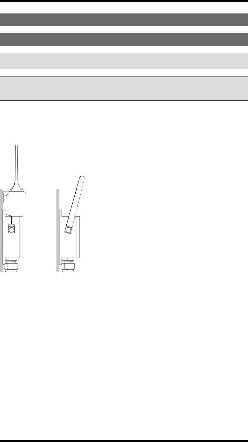
ANTENNA
NOTE! For optimum performance: Place well away from metal objects, such as metal girders, high-
voltage cables and other antennas.
NOTE! For optimum performance, place the antennas as far away from each other as possible. The
recommended distance is more than 1 meter. We recommend that you test the equipment before
mounting the receivers permanently.
Antenna with a cable: The cable makes it possible for the antenna to be positioned freely and high above
the ground.
Antenna without a cable:If the receiver is mounted on a wall, the antenna should be angled out from the
wall.
-7-
TG-RX-MNLANA,TG-RX-MNRANA,TG-RX-MNPANABASE
BOARDRECEIVERWITHANEXPANSIONBOARD
WARNING! The receiver must NOT be opened by any other than a qualified installer. Make sure to
turn the electricity off before opening the receiver.
WARNING! Tele Radio remote controls are often built into wider applications. We recommend that
the system is provided with a wired emergency stop where necessary.
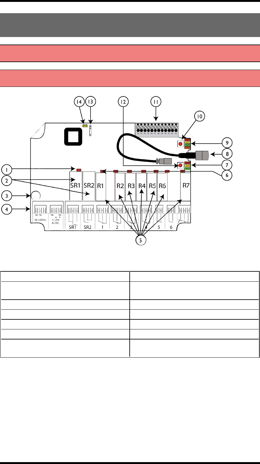
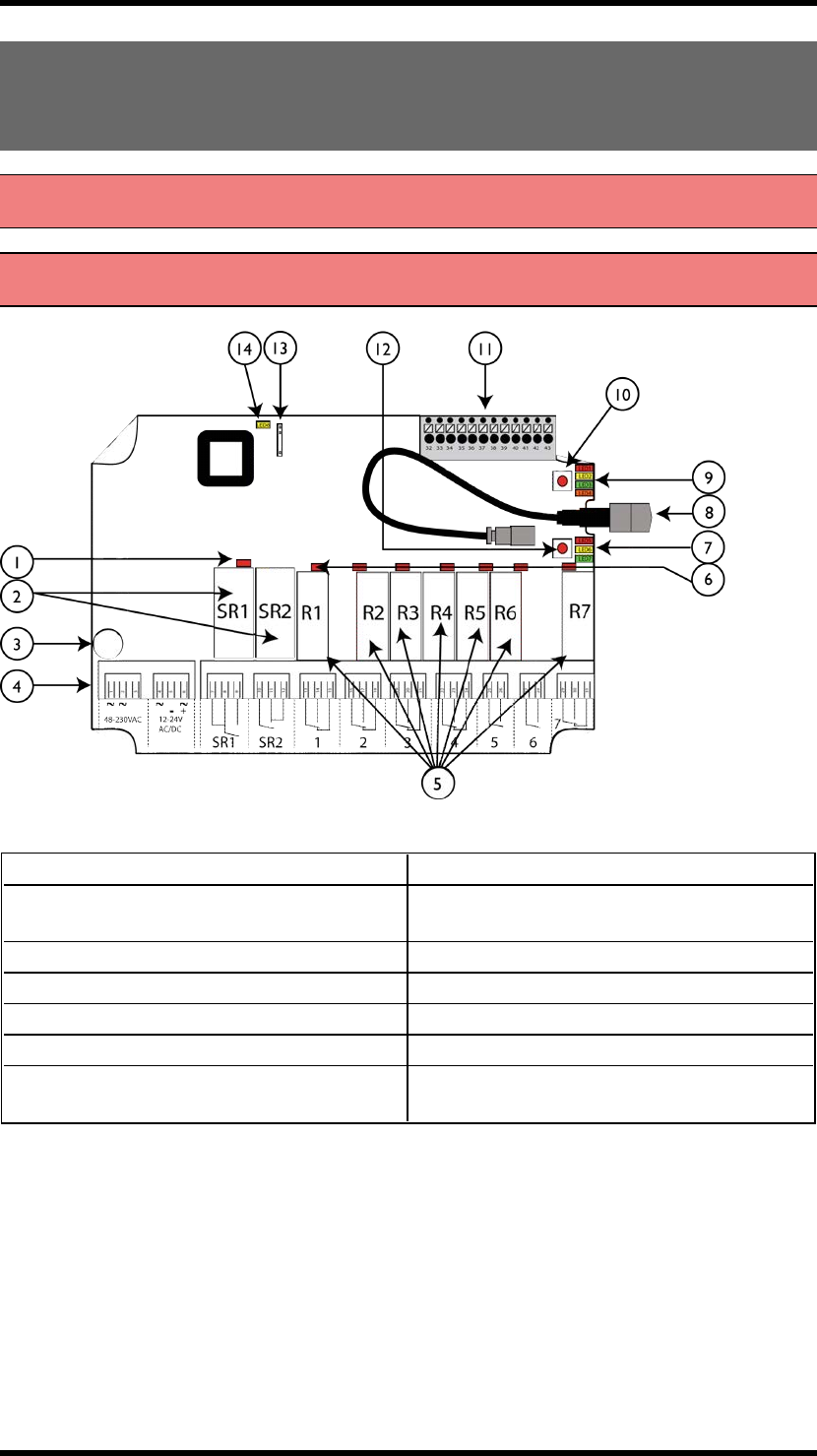
Base board:
1. LED representing stop relays 1+2 (red) 8. Antenna connector
2. Stop relays 1+2 9. Function LEDs 1-4 (1= red, 2= yellow, 3=
green, 4= orange)
3. Obligatory fuse 2A (slow) 10. Function button (Cancel)
4. Terminal block for input power 11. Terminal block for mixed I/O
5. Function relays 1-7 12. Select button (OK)
6. Relay LEDs 1-7 (red) 13. Programming connector
7. Function LEDs 5-7 (5= red, 6= yellow, 7=
green) 14. Power LED (yellow)
-8-
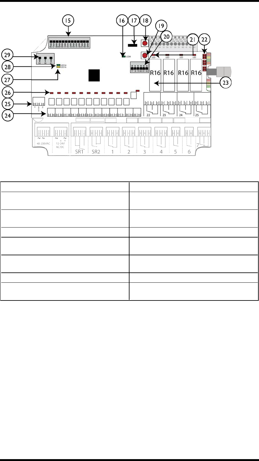
Expansion board:
15. Terminal block for analogue outputs 23. Function relays 22-25
16. Indication LED for communication with the
base board (green) 24. Terminal block for digital outputs
17. Programming connector 25. Terminal block for external analogue reference
and isolated analogue supply
18. Function button (Cancel) 26.Digital outputs LEDs
19. Select button (OK) 27. Indication LED for internal DC/DC converter
(yellow)
20. Terminal block for digital inputs 28. Indication LED for communication with the
base board (green)
21. Function relay LEDs (red) 29. Terminal block for analogue inputs
22. LEDs representing stop relays 1-2 and
function relays 1-7 on the base board
-9-
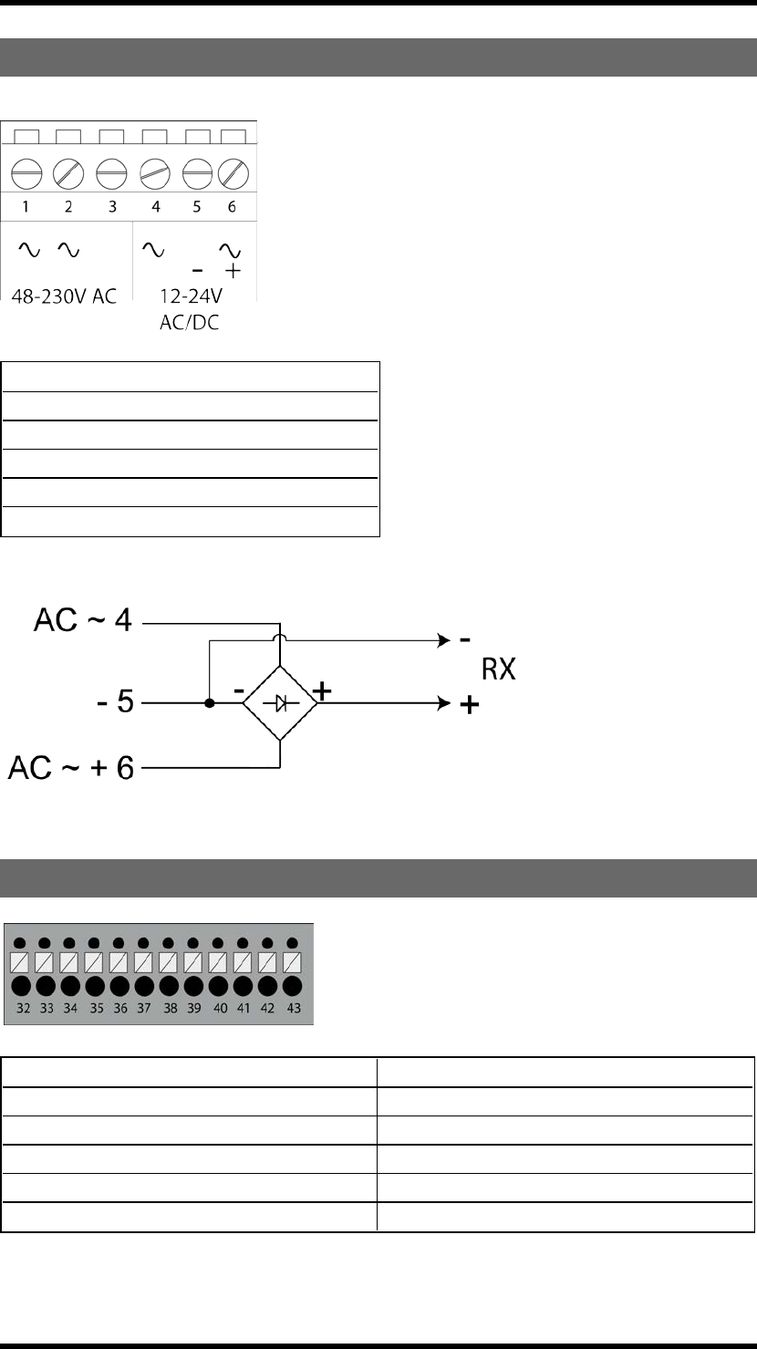
TERMINALBLOCKFORINPUTPOWER
1. 48-230 V AC
2. 48-230 V AC
3. (not used)
4. ~12-24 V AC/DC
5. negative terminal DC voltage*
6. ~+12-24 V AC/DC
* use when digital inputs are connected to receiver
TERMINALBLOCKFORMIXEDI/O
32. +12V DC 38. Digital input 2
33. +5V DC 39. GND
34. GND 40. +3.3V DC
35. GND 41. RS485A-
36. Digital input 1 42. RS485B+
37. Transistor output 43. GND
-10 -

FUNCTIONLEDSINDICATIONINOPERATINGMODE
FunctionLED Off On Indicates...
1 (red) X No transmitter is registered
X One or more transmitters are registered
2 (yellow) X No transmitter is logged in
X One transmitter is logged in
3 (green) X Receiving correct RS485 data
4 (orange) X Settings in the safety CPUs conform to SIL3
X Settings in the safety CPUs do NOT conform to SIL3
5 (red)
X FLASHES: The receiver is frequency scanning
X Automatic frequency control processing
X Automatic frequency control finetuned
6 (yellow) X Receiving correct sync word
7 (green) X Receiving correct radio packet
-11 -
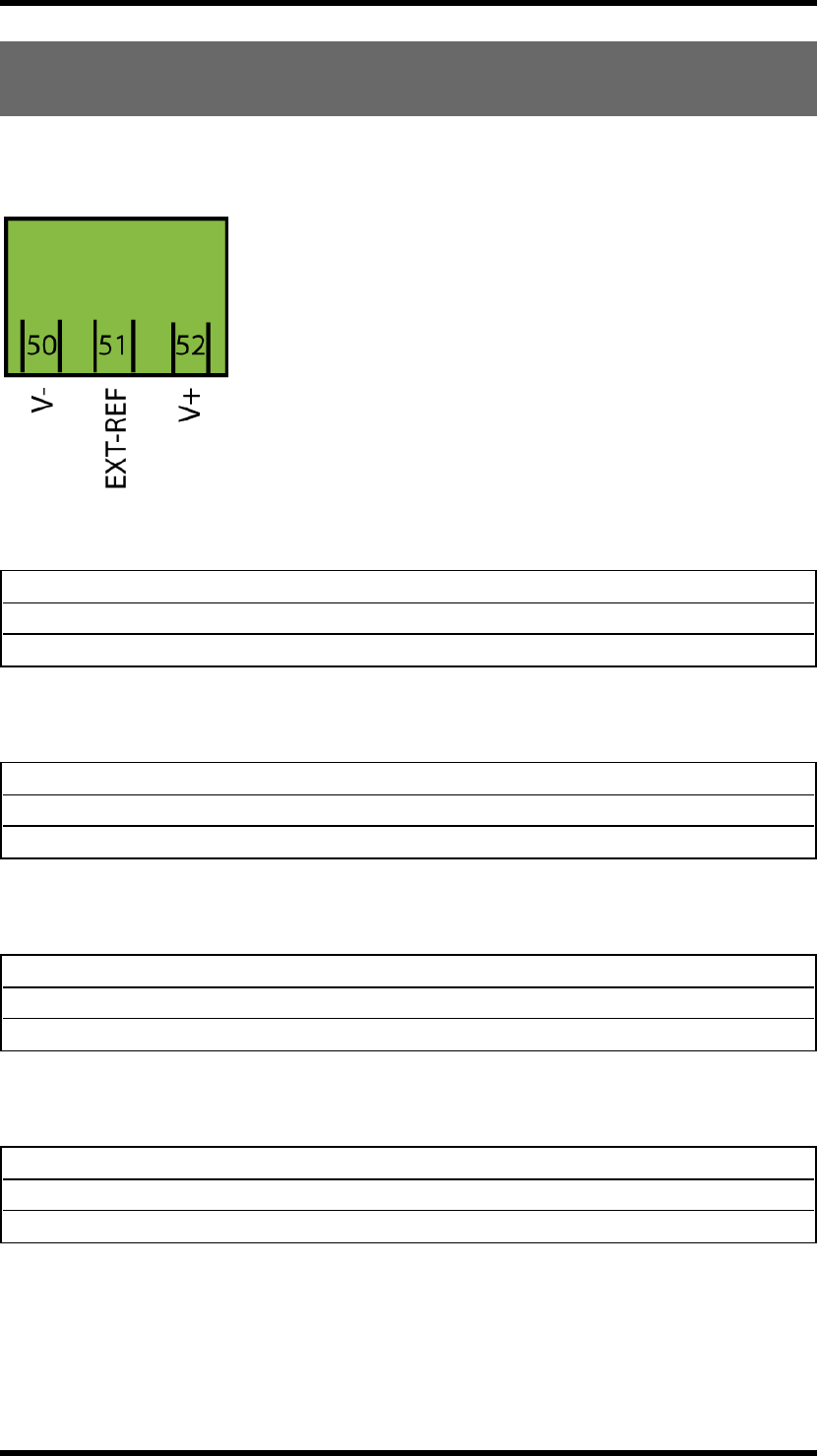
TERMINALBLOCKFOREXTERNALANALOGUEREFERENCE
ANDISOLATEDANALOGUESUPPLY
How to connect to the terminal block depends on the configurations made to the receiver. Please,
contact your Tele Radio representative for further assistance.
50. Unconnected
51. Unconnected
52. Unconnected
0 to +10V analogue output, internal DC/DC converter on:
50. Negative supply
51. Unconnected
52. Positive supply
0 to +10V analogue output, internal DC/DC converter off:
50. Unconnected
51. External reference*
52. Unconnected
-10 to +10V analogue output, internal DC/DC converter on***:
50. Negative supply
51. External reference*
52. Positive supply
-10 to +10V analogue output, internal DC/DC converter off**:
-12 -
50. Negative supply
51. Unconnected
52. Positive supply
25-75% or 10-90% output****:
* Analogue output reference will follow this voltage. If unconnected, the analogue output reference will
be in the middle of the external supply voltage.
** External supply voltage of 22-35V DC is required to achieve full -10 to +10V output.
*** External supply voltage shall not be connected. Guaranteed output range is -5 to +5V.
**** Internal DC/DC converter is always off. The analogue output voltage is 25-75% or 10-90% of the
supply voltage, depending on the configurations of the receiver.
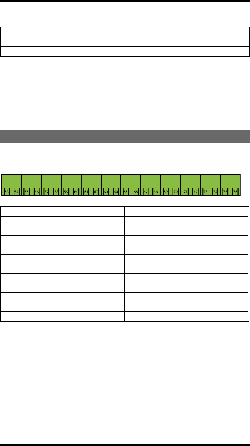
TERMINALBLOCKFORDIGITALOUTPUTS
There are 12 digital outputs on the expansion board. The digital outputs can be remapped as with the
relays. Maximum input is 50V, 30 mA.
53. Digital output 10 65. Digital output 16
54. Digital output 10 reference 66. Digital output 16 reference
55. Digital output 11 67. Digital output 17
56. Digital output 11 reference 68. Digital output 17 reference
57. Digital output 12 69. Digital output 18
58. Digital output 12 reference 70. Digital output 18 reference
59. Digital output 13 71. Digital output 19
60. Digital output 13 reference 72. Digital output 19 reference
61. Digital output 14 73. Digital output 20
62. Digital output 14 reference 74. Digital output 20 reference
63. Digital output 15 75. Digital output 21
64. Digital output 15 reference 76. Digital output 21 reference
-13 -
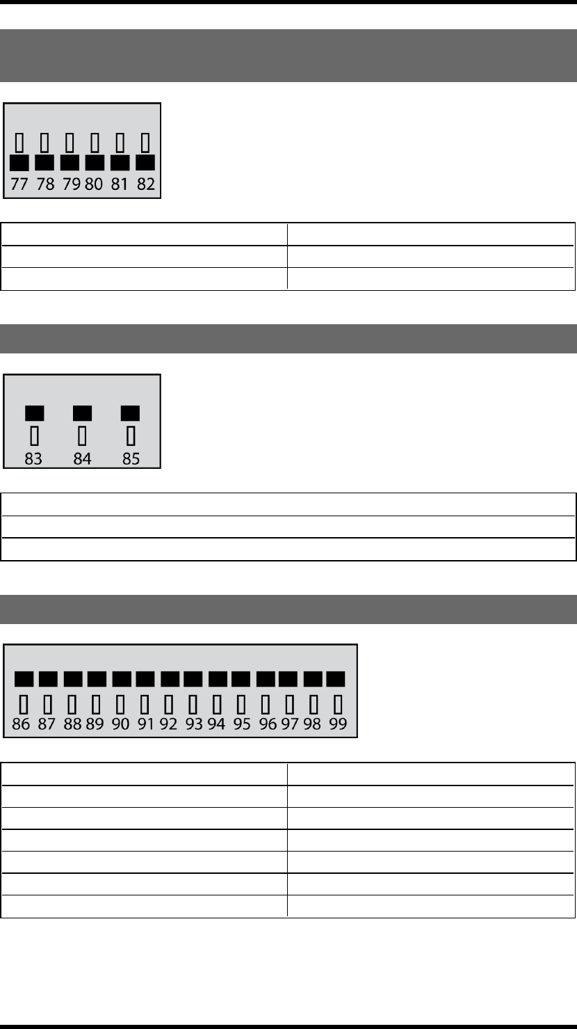
TERMINALBLOCKFORDIGITALINPUTSANDGROUND
CONNECTIONS
77. Digital input 3 80. GND
78. Digital input 4 81. GND
79. Digital input 5 82. GND
TERMINALBLOCKFORANALOGUEINPUTS
83. Analogue input 1
84. Analogue input 2
85. Analogue GND
TERMINALBLOCKFORANALOGUEOUTPUTS
86. Analogue GND 93. Analogue output 1
87. Analogue GND 94. Analogue output 2
88. Analogue GND 95. Analogue output 3
89. Analogue GND 96. Analogue output 4
90. Analogue GND 97. Analogue output 5
91. Analogue GND 98. Analogue output 6
92. Analogue GND 99. Analogue output 7
-14 -
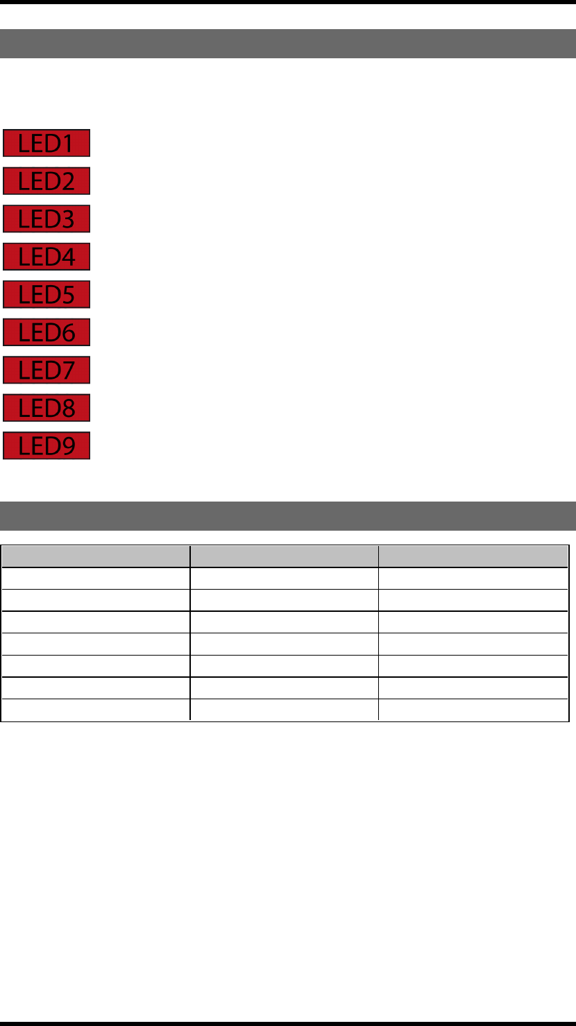
BASEBOARDRELAYLEDS
These LEDs light when the corresponding stop and function relays on the base board are activated. See
list for corresponding base board relay.
LED 1 = function relay 1
LED 2 = function relay 2
LED 3 = function relay 3
LED 4 = function relay 4
LED 5 = function relay 5
LED 6 = function relay 6
LED 7 = function relay 7
LED 8 = (not used)
LED 9 = stop relays 1 + 2
CURRENTCONSUMPTION
Input power Min.* Max.**
12V AC 0.2A 0.5A
24V AC 0.06A 0.2A
48V AC 0.04A 0.2A
115V AC 0.02A 0.06A
230V AC 0.01A 0.04A
12V DC 0.1A 0.5A
24V DC 0.06A 0.2A
* Minimum current consumption= Receiver powered, no radio session established, nothing else
activated on the receiver
** Maximum current consumption= All relays activated on the receiver
-15 -

TECHNICALDATA
Number of stop relays 2 (potential free*, 16A, 250VAC)
Number of function relays 7 (potential free*, 10A, 250VAC)
Digital inputs 2
Input power 48-230V AC, 12-24V AC/DC
Transistor output 1
Duplex communication Possible
Max. number of registered
transmitters 15 (only one transmitter at a time)
IP class 66
Size 176 x 126 x 75 mm./ 6.9 x 5 x 2.9 in.
Weight 800 g./ 1.8 lbs.
Sensitivity Better than -110 dBm
Operating temperature -20- +55°C/ -4-+130°F
Operating frequency
TG-RX-MNLANA: 433.075-434.775 MHz
TG-RX-MNRANA: 903.0125-926.9875 MHz
TG-RX-MNPANA: 2405-2480 MHz
Number of channels/frequency banks
TG-RX-MNLANA: 69 channels
TG-RX-MNRANA: 15 banks
TG-RX-MNPANA: 16 channels
Channel separation
TG-RX-MNLANA: 25 kHz
TG-RX-MNRANA: 25 kHz
TG-RX-MNPANA: 5 MHz
Antenna
TG-RX-MNLANA: 1 external BNC antenna
TG-RX-MNRANA: 1 external RPSMA antenna
TG-RX-MNPANA: 1 external RPSMA antenna
* potential free means that you have to supply voltage to get voltage out of a relay (e.g. via the included
connection comb)
-16 -
TG-RX-MNLCAN,TG-RX-MNRCAN,TG-RX-MNPCAN,TG-RX-
MNLJ1939,TG-RX-MNRJ1939,TG-RX-MNPJ1939BASEBOARD
RECEIVERWITHCANEXPANSIONBOARD
WARNING! The receiver must NOT be opened by any other than a qualified installer. Make sure to
turn the electricity off before opening the receiver.
WARNING! Tele Radio remote controls are often built into wider applications. We recommend that
the system is provided with a wired emergency stop where necessary.
Base board:
1. LED representing stop relays 1+2 (red) 8. Antenna connector
2. Stop relays 1+2 9. Function LEDs 1-4 (1= red, 2= yellow, 3=
green, 4= orange)
3. Obligatory fuse 2A (slow) 10. Function button (Cancel)
4. Terminal block for input power 11. Terminal block for mixed I/O
5. Function relays 1-7 12. Select button (OK)
6. Relay LEDs 1-7 (red) 13. Programming connector
7. Function LEDs 5-7 (5= red, 6= yellow, 7=
green) 14. Power LED (yellow)
-17 -
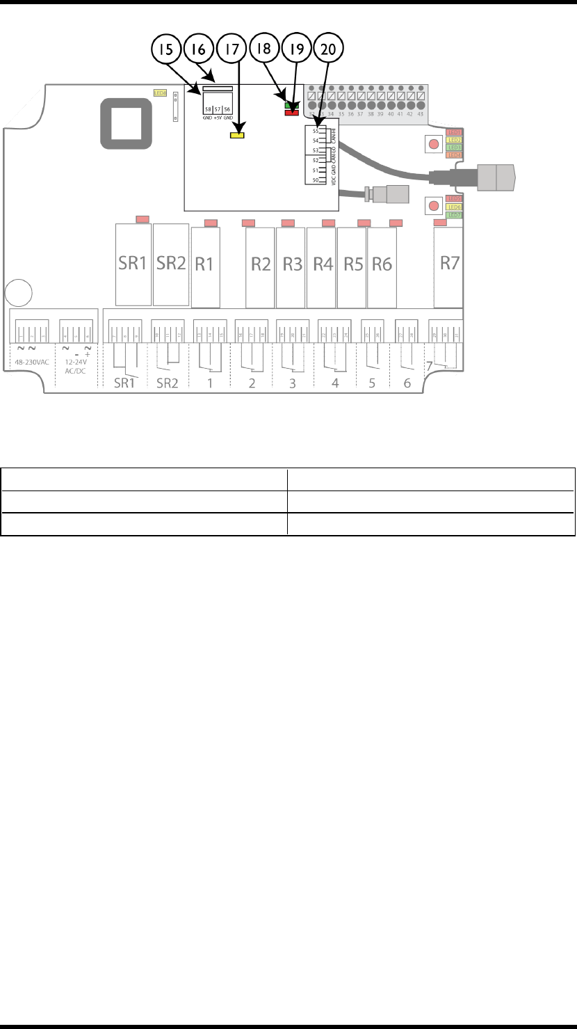
Expansion board:
15. Terminal block for internal power supply 18. CAN run LED
16. Programming connector 19. CAN error LED
17. Power LED 20. Terminal block for CAN signals
-18 -

TERMINALBLOCKFORINPUTPOWER
1. 48-230 V AC
2. 48-230 V AC
3. (not used)
4. ~12-24 V AC/DC
5. negative terminal DC voltage*
6. ~+12-24 V AC/DC
* use when digital inputs are connected to receiver
TERMINALBLOCKFORMIXEDI/O
32. +12V DC 38. Digital input 2
33. +5V DC 39. GND
34. GND 40. +3.3V DC
35. GND 41. RS485A-
36. Digital input 1 42. RS485B+
37. Transistor output 43. GND
-19 -
FUNCTIONLEDSINDICATIONINOPERATINGMODE
FunctionLED Off On Indicates...
1 (red) X No transmitter is registered
X One or more transmitters are registered
2 (yellow) X No transmitter is logged in
X One transmitter is logged in
3 (green) X Receiving correct RS485 data
4 (orange) X Settings in the safety CPUs conform to SIL3
X Settings in the safety CPUs do NOT conform to SIL3
5 (red)
X FLASHES: The receiver is frequency scanning
X Automatic frequency control processing
X Automatic frequency control finetuned
6 (yellow) X Receiving correct sync word
7 (green) X Receiving correct radio packet
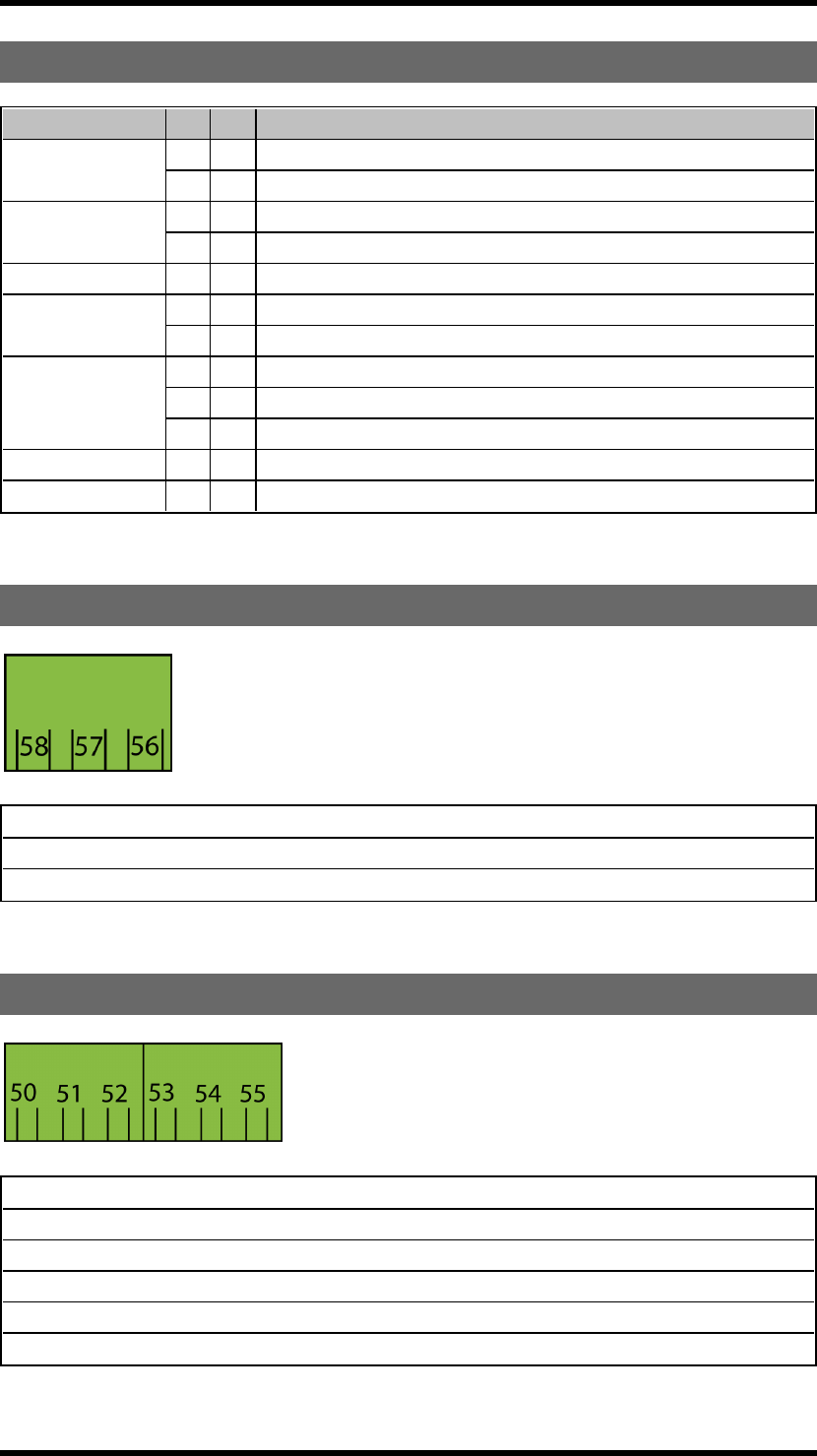
TERMINALBLOCKFORINTERNALPOWERSUPPLY
58. GND
57. +5V DC
56. GND
TERMINALBLOCKFORCANSIGNALS
50. Supply voltage 5-24VDC
51. GND
52. CAN Low
53. CAN Low
54. CAN High
55. CAN High
-20 -

TECHNICALDATA
Number of stop relays 2 (potential free*, 16A, 250VAC)
Number of function relays 7 (potential free*, 10A, 250VAC)
Digital inputs 2
Input power 48-230V AC, 12-24V AC/DC
Transistor output 1
Duplex communication Possible
Max. number of registered
transmitters 15 (only one transmitter at a time)
IP class 66
Size 176 x 126 x 75 mm./ 6.9 x 5 x 2.9 in.
Weight 800 g./ 1.8 lbs.
Sensitivity Better than -110 dBm
Operating temperature -20- +55°C/ -4-+130°F
Operating frequency
TG-RX-MNLCAN, TG-RX-MNLJ1939: 433.075-
434.775 MHz
TG-RX-MNRCAN, TG-RX-MNRJ1939:
903.0125-926.9875 MHz
TG-RX-MNPCAN, TG-RX-MNPJ1939:
2405-2480 MHz
Number of channels/ frequency banks
TG-RX-MNLCAN, TG-RX-MNLJ1939: 69 chan..
TG-RX-MNRCAN, TG-RX-MNRJ1939: 15 banks
TG-RX-MNPCAN, TG-RX-MNPJ1939: 16 chan.
Channel separation 25 kHz
TG-RX-MNLCAN, TG-RX-MNLJ1939: 25 kHz
TG-RX-MNRCAN, TG-RX-MNRJ1939:
25 kHz
TG-RX-MNPCAN, TG-RX-MNPJ1939: 5 MHz
Antenna
TG-RX-MNLCAN, TG-RX-MNLJ1939:
1 external BNC antenna
TG-RX-MNRCAN, TG-RX-MNRJ1939:
1 external RPSMA antenna
TG-RX-MNPCAN, TG-RX-MNPJ1939:
1 external RPSMA antenna
*potential free means that you have to supply voltage to get voltage out of a relay (e.g. via the included
connection comb.
-21 -

CURRENTCONSUMPTION
Input power Min.* Max.**
12V AC 0.06A 0.4A
24V AC 0.03A 0.2A
48V AC 0.02A 0.09A
115V AC 0.008A 0.04A
230V AC 0.006A 0.03A
12V DC 0.06A 0.3A
24V DC 0.03A 0.2A
* Minimum current consumption= Receiver powered, no radio session established, nothing else
activated on the receiver
** Maximum current consumption= All relays activated on the receiver
-22 -
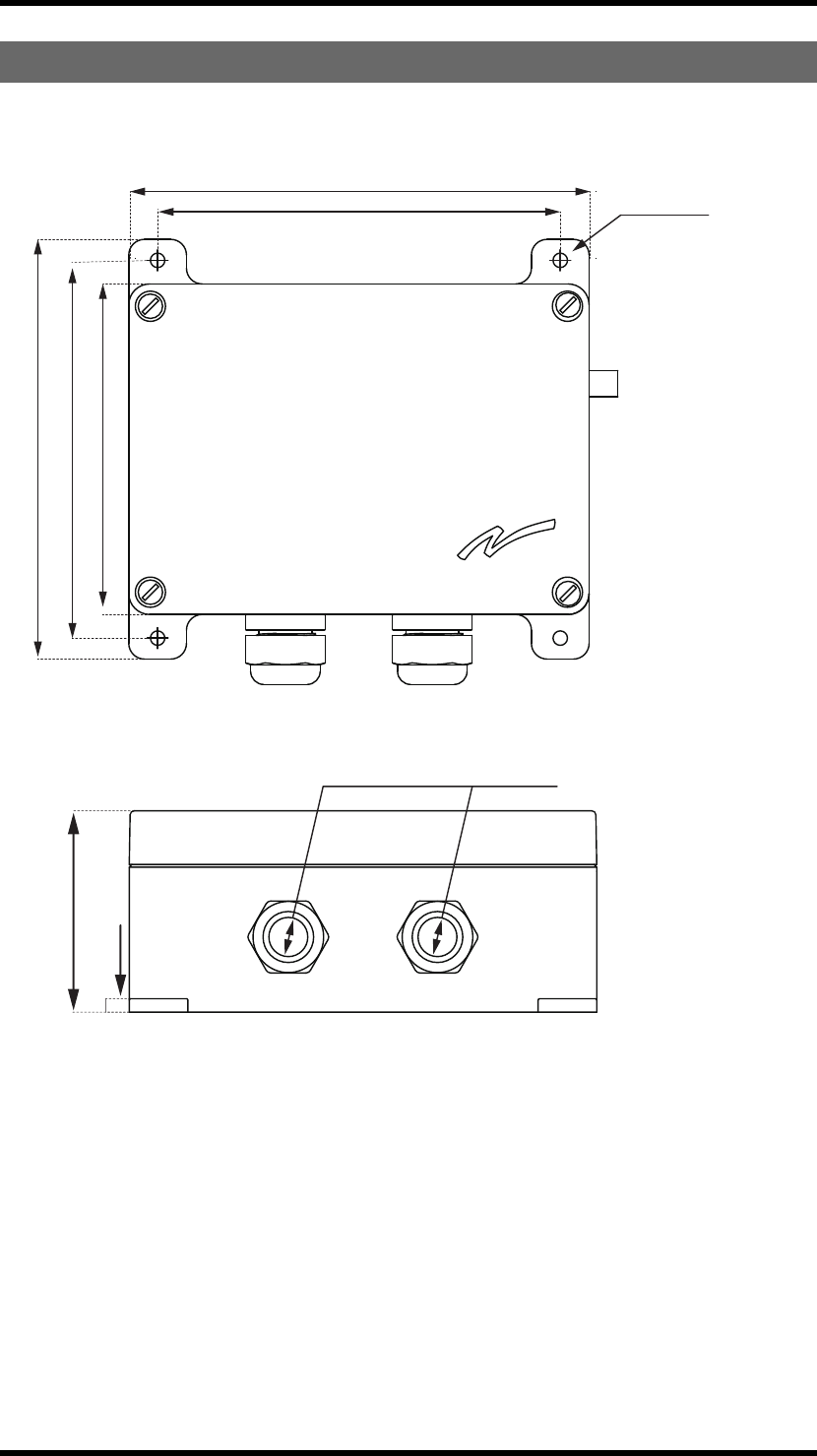
RECEIVERMEASUREMENTS
TG-RX-MNLANA, TG-RX-MNRANA, TG-RX-MNPANA
176 mm (6.9 in)
160 mm (6.3 in)
154 mm (6 in)
144 mm (5.7 in)
126 mm (5 in)
Ø5.5 mm
(0.2 in)
75 mm (3 in)
5 mm (0.2 in)
Ø15 mm (0.6 in)
Ø5.5 mm
(0.2 in)
75 mm (3 in)
160 mm (6.3 in)
160 mm (6.3 in)
-23 -
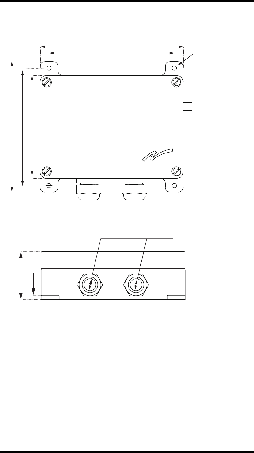
TG-RX-MNLCAN, TG-RX-MNRCAN, TG-RX-MNPCAN, TG-RX-MNLJ1939,
TG-RX-MNRJ1939, TG-RX-MNPJ1939
176 mm (6.9 in)
160 mm (6.3 in)
154 mm (6 in)
144 mm (5.7 in)
126 mm (5 in)
Ø5.5 mm
(0.2 in)
53 mm (2.1 in)
5 mm (0.2 in)
Ø9 mm (0.4 in)
Ø5.5 mm
(0.2 in)
53 mm (2.1 in)
160 mm (6.3 in)
53 mm (2.1 in)53 mm (2.1 in)
160 mm (6.3 in)
53 mm (2.1 in)53 mm (2.1 in)
-24 -
TG-T14-4,TG-T14-5,TG-T14-6,TG-T14-7,TG-T14-8,TG-T14-9,
TG-T15-4,TG-T15-5,TG-T15-6,TG-T15-7,TG-T15-8,TG-T15-9
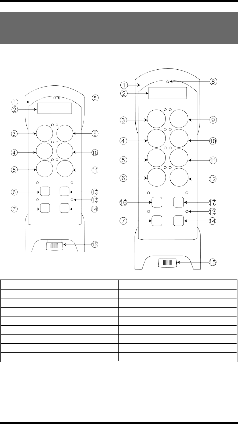
TRANSMITTER
TG-T15-4,TG-T15-5,TG-T15-6,TG-T15-7,TG-T15-8,TG-T15-9
1. Rubber cover 10. Button 4
2. Display 11. Button 6
3. Button 1 12. Button 8 (safe button*)
4. Button 3 13. Button LEDs
5. Button 5 14. Right start button
6. Button 7 (safe button*) 15. Stop button
7. Left start button 16. Button 9 (safe button**)
8. Top led 17. Button 10 (safe button**)
9. Button 2
* On TG-T14-4, TG-T14-5, TG-T14-6, TG-T14-7, TG-T14-8, TG-T14-9
** On TG-T15-4, TG-T15-5, TG-T15-6, TG-T15-7, TG-T15-8, TG-T15-9
-25 -
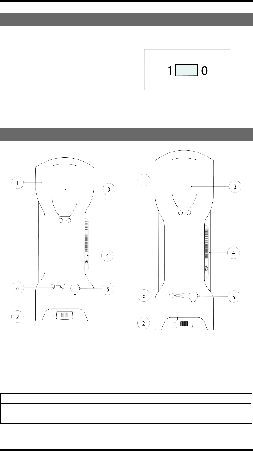
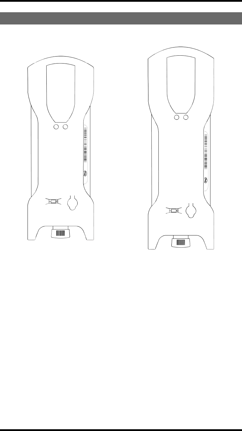
ON/OFFSWITCH
The transmitters have an on/off switch on the
backside. The switch breaks the power supply
from the battery. When in position 0/off, the
transmitter cannot be started unless you connect
the charger plug. When the transmitter is
transported by airplane, the on/off switch must
be in 0/off position. The switch should not be
used as an on/off button for the transmitter. To
turn the transmitter off, use the stop button.
BUTTONTRANSMITTERBACKSIDE
TG-T14-4
TG-T14-5
TG-T14-6
TG-T14-7
TG-T14-8
TG-T14-9
TG-T15-4
TG-T15-5
TG-T15-6
TG-T15-7
TG-T15-8
TG-T15-9
1. Rubber cover 4. CE and product label
2. Stop button 5. Battery charger socket
3. Clip 6. On/off switch
-26 -
TECHNICALDATA
NO. OFBUTTONS
TG-T14-4, TG-T14-5, TG-T14-6, TG-T14-7, TG-
T14-8, TG-T14-9 4 x 2-step buttons, 6 analogue buttons
TG-T15-4, TG-T15-5, TG-T15-6, TG-T15-7, TG-
T15-8, TG-T15-9 4 x 2-step buttons, 8 analogue buttons
BATTERY
TG-T14-4, TG-T14-5, TG-T14-6, TG-T14-7, TG-
T14-8, TG-T14-9, TG-T15-4, TG-T15-5, TG-
T15-6, TG-T15-7, TG-T15-8, TG-T15-9
Internal, rechargeable lithium-ion
ON/OFF SWITCH
TG-T14-4, TG-T14-5, TG-T14-6, TG-T14-7, TG-
T14-8, TG-T14-9, TG-T15-4, TG-T15-5, TG-
T15-6, TG-T15-7, TG-T15-8, TG-T15-9
Yes
DUPLEX COMMUNICATION
TG-T14-4, TG-T14-5, TG-T14-6, TG-T14-7, TG-
T14-8, TG-T14-9, TG-T15-4, TG-T15-5, TG-
T15-6, TG-T15-7, TG-T15-8, TG-T15-9
Possible
MAX. NO OF REGISTERED RECEIVERS
TG-T14-4, TG-T14-5, TG-T14-6, TG-T14-7, TG-
T14-8, TG-T14-9 8
TG-T15-4, TG-T15-5, TG-T15-6, TG-T15-7, TG-
T15-8, TG-T15-9 10
SIZE
TG-T14-4, TG-T14-5, TG-T14-6, TG-T14-7, TG-
T14-8, TG-T14-9 220 x 79 x 56 mm./ 8.7 x 3.1 x 2.2 in.
TG-T15-4, TG-T15-5, TG-T15-6, TG-T15-7, TG-
T15-8, TG-T15-9 245 x 79 x 56 mm./ 9.6 x 3.1 x 2.2 in.
WEIGHT
TG-T14-4, TG-T14-5, TG-T14-6, TG-T14-7, TG-
T14-8, TG-T14-9 400 g./ 0.9 lbs.
TG-T15-4, TG-T15-5, TG-T15-6, TG-T15-7, TG-
T15-8, TG-T15-9 460 g./ 1.0 lbs.
OPERATING FREQUENCY
TG-T14-4, TG-T14-7, TG-T15-4, TG-T15-7 433.075-434.775 MHz
TG-T14-5, TG-T14-8, TG-T15-5, TG-T15-8 903.0125-926.9875 MHz
TG-T14-6, TG-T14-9, TG-T15-6, TG-T15-9 2405-2480 MHz
-27 -
NO. OF CHANNELS/FREQUENCY BANKS
TG-T14-4, TG-T14-7, TG-T15-4, TG-T15-7 69 channels
TG-T14-5, TG-T14-8, TG-T15-5, TG-T15-8 15 banks
TG-T14-6, TG-T14-9, TG-T15-6, TG-T15-9 16 channels
CHANNEL SEPARATION
TG-T14-4, TG-T14-7, TG-T15-4, TG-T15-7,
TG-T14-5, TG-T14-8, TG-T15-5, TG-T15-8 25 kHz
TG-T14-6, TG-T14-9, TG-T15-6, TG-T15-9 5 MHz
OPERATING TIME (WITH CONTINUOUS USAGE)
TG-T14-4, TG-T14-5, TG-T14-6, TG-T14-7, TG-
T14-8, TG-T14-9, TG-T15-4, TG-T15-5, TG-
T15-6, TG-T15-7, TG-T15-8, TG-T15-9
16 h.
IP CLASS
TG-T14-4, TG-T14-5, TG-T14-6, TG-T14-7, TG-
T14-8, TG-T14-9, TG-T15-4, TG-T15-5, TG-
T15-6, TG-T15-7, TG-T15-8, TG-T15-9
66
SENSITIVITY
TG-T14-4, TG-T14-5, TG-T14-6, TG-T14-7, TG-
T14-8, TG-T14-9, TG-T15-4, TG-T15-5, TG-
T15-6, TG-T15-7, TG-T15-8, TG-T15-9
Better than -110 dBm
OPERATING TEMPERATURE
TG-T14-4, TG-T14-5, TG-T14-6, TG-T14-7, TG-
T14-8, TG-T14-9, TG-T15-4, TG-T15-5, TG-
T15-6, TG-T15-7, TG-T15-8, TG-T15-9
-20 - +55°C/ -4 - +130°F
NO. OF PIN CODES POSSIBLE
TG-T14-4, TG-T14-5, TG-T14-6, TG-T14-7, TG-
T14-8, TG-T14-9, TG-T15-4, TG-T15-5, TG-
T15-6, TG-T15-7, TG-T15-8, TG-T15-9
10
ANTENNA
TG-T14-4, TG-T14-5, TG-T14-6, TG-T14-7, TG-
T14-8, TG-T14-9, TG-T15-4, TG-T15-5, TG-
T15-6, TG-T15-7, TG-T15-8, TG-T15-9
1 internal PCB antenna
-28 -
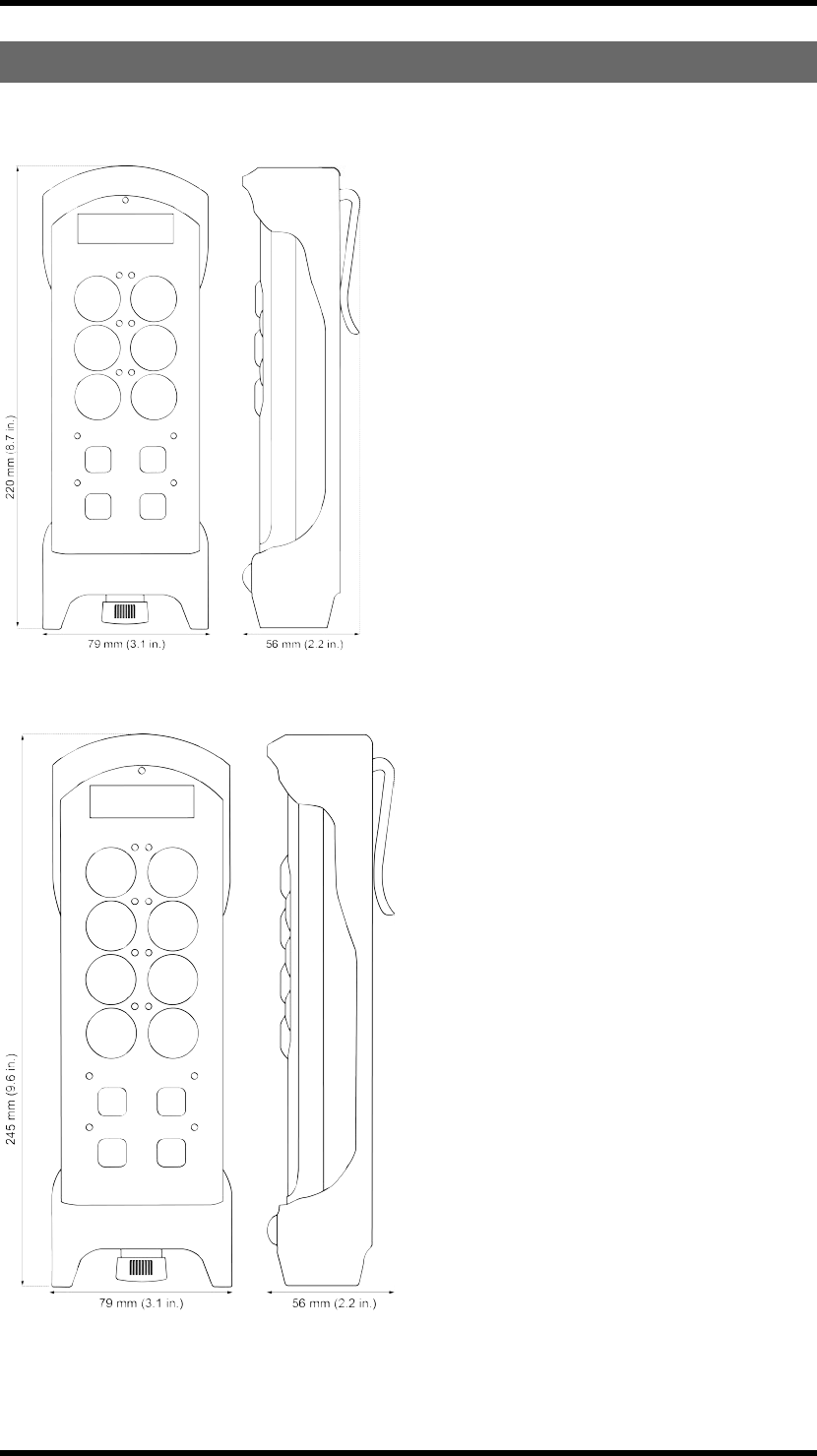
TRANSMITTERMEASUREMENTS
TG-T14-4, TG-T14-5, TG-T14-6, TG-T14-7, TG-T14-8, TG-T14-9
TG-T15-4, TG-T15-5, TG-T15-6, TG-T15-7, TG-T15-8, TG-T15-9
-29 -
Chapter 4: INSTALLERS GUIDE
CHAPTER 4: INSTALLERS GUIDE
NAVIGATEINMENUMODE
To navigate when in menu mode:
Press... to...
Button 1 Step down
Button 2 Step up
Button 3 Step left/ go back
Button 4 Step right
The left start button Select/ confirm
The right start button Exit
ENABLEPINCODES
1. Make sure that the stop button is pressed.
2. Twist and pull out the stop button.
The top LED lights (green when the battery capacity is good, red when the battery capacity is poor).
3. Press the right start button. Keep pressed.
4. Press the stop button.
5. Release the right start button.
The top LED flashes (green when the battery capacity is good, red when the battery capacity is poor)
when in menu mode.
6. Go to [Startup Protect.].
7. Select one or more start-up protection choices by pressing the left start button.
Select... to...
[Stored PIN] Only accept PIN codes registered in the trans-
mitter
[Any PIN] Accept any PIN code
[Allow skip] Allow to skip any start-up
authorization
8. Confirm by pressing the left start button.
-30 -
CREATEPINCODES
NOTE! You can store up to 10 PIN codes in the transmitter.
NOTE! '0000' is not a valid PIN code.
1. Make sure that the stop button is pressed.
2. Twist and pull out the stop button.
The top LED lights (green when the battery capacity is good, red when the battery capacity is poor).
3. Press the right start button. Keep pressed.
4. Press the stop button.
5. Release the right start button.
The top LED flashes (green when the battery capacity is good, red when the battery capacity is poor)
when in menu mode.
6. Go to [PIN] --> [Enter PIN].
7. Select what position in the list that you want to store the new PIN code in by pressing the left start
button.
8. Enter the new PIN code (4 digits) by pressing the buttons 1-4:
Press... to...
Button 1 Step up
Button 2 Step down
Button 3 Step right
Button 4 Step left
9. Confirm by pressing the left start button.
-31 -

ERASEPINCODES
1. Make sure that the stop button is pressed.
2. Twist and pull out the stop button.The LEDs light (green when the battery capacity is good, red when
the battery capacity is poor).
3. Press the right start button. Keep pressed.
4. Press the stop button.
5. Release the right start button.
The LEDs light (green when the battery capacity is good, red when the battery capacity is poor) when in
menu mode.
6. Go to [PIN] --> [Erase PIN].
7. Scroll the list to select the PIN code that you want to erase.
8. Select by pressing the left start button.
9. Confirm by pressing the left start button.
SHOWREGISTEREDPINCODES
1. Make sure that the stop button is pressed.
2. Twist and pull out the stop button.
The top LED lights (green when the battery capacity is good, red when the battery capacity is poor).
3. Press the right start button. Keep pressed.
4. Press the stop button.
5. Release the right start button.
The top LED flashes (green when the battery capacity is good, red when the battery capacity is poor)
when in menu mode.
6. Go to [PIN] --> [Show PIN].
7. The display shows a list of all registered PIN codes.
-32 -

STARTTHETRANSMITTERINOPERATINGMODE
1. Make sure that the stop button is pressed
2. Twist and pull out the stop button.
The top LED lights (green when the battery capacity is good, red when the battery capacity is poor).
3. If PIN codes are used for authorization: Go to the next section.
4. WITHIN 3 MINUTES FROM PULLING OUTTHESTOPBUTTON:
Press a button to select the receiver(s) that you want to operate.
The receiver(s) that was selected in the last session will be automatically selected, which is indicated by
the corresponding LED(s) that light red. If no receiver(s) has been selected, the LEDs for all available
receivers will flash red. If a receiver is selected, the LEDs next to the left and the right start buttons flash
red. If no receiver(s) are selected, only the LED next to the right start button flashes red.
5. Press both start buttons at the same time.
The buzzer beeps.
6. Release the start buttons.
The buzzer stops beeping. The top LED flashes (green when the battery capacity is good, red when the
battery capacity is poor).
7. When radio communication has been established, the top LED lights (green when the battery
capacity is good, red when the battery capacity is poor).
If radio communication is not established within 25 seconds, the transmitter turns off.
-33 -

STARTTHETRANSMITTERINOPERATINGMODEWITHPIN
CODES
1. Make sure that the stop button is pressed.
2. Twist and pull out the stop button.
The top LED lights (green when the battery capacity is good, red when the battery capacity is poor).
3. WITHIN 3 MINUTES : Enter the PIN code (4 digits) by pressing the buttons according to the table.
Fordigit: 1 2 3 4 5 6 7 8 9 0
TG-T14-4, TG-T14-5, TG-T14-6, TG-T14-7,
TG-T14-8, TG-T14-9, PRESSBUTTON: 12345678- -
TG-T15-4, TG-T15-5, TG-T15-6, TG-T15-7,
TG-T15-8, TG-T15-9, PRESSBUTTON: 123456789 10
4. WITHIN 3 MINUTES FROM PULLING OUTTHESTOPBUTTON:
Press a button to select the receiver(s) that you want to operate.
The receiver(s) that was selected in the last session will be automatically selected, which is indicated by
the corresponding LED(s) that light red. If no receiver(s) has been selected, the LEDs for all available
receivers will flash red. If a receiver is selected, the LEDs next to the left and the right start buttons flash
red. If no receiver(s) are selected, only the LED next to the right start button flashes red.
5. Press both start buttons at the same time.
The buzzer beeps.
6. Release the start buttons.
The buzzer stops beeping. The top LED flashes (green when the battery capacity is good, red when the
battery capacity is poor).
7. When radio communication has been established, the top LED lights (green when the battery
capacity is good, red when the battery capacity is poor).
If radio communication is not established within 25 seconds, the transmitter turns off.
TURNTHETRANSMITTEROFF
1. Press the stop button. The transmitter turns off. All relays deactivate.
-34 -

LOGIN/LOGOUT
NOTE! When the transmitter has established radio communication with one or more receivers, you
can make a Quick logout from those receivers. Note that the Quick logout will log the transmitter out
from all receivers that are participating in the session.
NOTE! If you need to log out a transmitter that is lost or damaged, it is possible to log out from the
receiver. We do not recommend this way of logging out. Contact your representative for assistance.
NOTE! To be able to control a receiver, the transmitter must be registered in the receiver, and logged
in to the receiver. If another transmitter is already logged in to the receiver, it has to be logged out
before any other transmitter can be logged in. If no transmitter is logged in to a receiver, a registered
transmitter will automatically log in when sending radio signals to the receiver. The transmitter will stay
logged in until it is manually logged out. More than one transmitter can be registered in the receiver, but
only one transmitter can be logged in at a time.
Quick logout
1. Make sure that the transmitter is started in operating mode.
NOTE! The transmitter must have established a radio session with one or more receivers.
2. Press the left start button. Keep pressed.
3. Press the stop button.
4. Release the left start button.
The top LED lights red.
The display shows [Logging out].
The transmitter turns off after logging out.
-35 -

Logout from menu mode
1. Make sure that the stop button is pressed.
2. Twist and pull out the stop button.
The top LED lights (green when the battery capacity is good, red when the battery capacity is poor).
3. Press the right start button. Keep pressed.
4. Press the stop button.
5. Release the right start button.
The top LED flashes (green when the battery capacity is good, red when the battery capacity is poor)
when in menu mode.
6. Go to [Logout].
7. Select by pressing the left start button.
8. Select a receiver to log out from.
9. Confirm by pressing the left start button.
The display shows [Logging out...] while the process is ongoing.
If logout fails, the display shows [FAILED]. The transmitter turns off.
If logout succeeds, the display shows [OK]. The transmitter turns off after logging out.
REGISTER
WARNING! Do not perform this when the receiver is in a session with another transmitter. The radio
communication may become disturbed or broken.
NOTE! Before starting to perform these settings, make sure that the stop relays are deactivated!
Register the transmitter in the receiver
1. Press the receiver Function button.
Function LED 1 flashes red.
2. Relay LEDs 1-7 light to show how many transmitters that are already registered in the receiver.
3. Press the receiver Select button until all relay LEDs light red.
The receiver will stay in registering mode for 1 minute or until a transmitter has been registered.
4. On the transmitter: Make sure that the stop button is pressed.
5. Twist and pull out the stop button.
The top LED lights (green when the battery capacity is good, red when the battery capacity is poor).
6. Press the right start button. Keep pressed.
7. Press the stop button.
8. Release the right start button.
-36 -

The top LED flashes (green when the battery capacity is good, red when the battery capacity is poor)
when in menu mode.
9. Go to [Register].
10. Select an empty slot and confirm by pressing the left start button. The display shows [Registering] .
11. When the receiver has found the transmitter, all relay LEDs flash red. The display shows [Confirm
on RX].
12. Press the receiver Select button. Function LEDs 1-7 flash 3 times. The relay LEDs go off.
13. All Function LEDs light for approx. 1 second. The transmitter is now registered in the receiver. The
transmitter turns off.
14. If registering fails, the display shows [FAILED]. The transmitter turns off.
ERASE
WARNING! If a transmitter is lost or becomes seriously damaged, it is possible to erase it from the
receiver. We do not recommend this way. Contact your representative for assistance.
NOTE! If the transmitter already have receivers registered, we recommend that you erase all receivers
from the transmitter before starting the replacement. The receiver will automatically be stored in the
same position as it was stored in the old transmitter. If this position is not available, the replacement will
not take place.
1. Make sure that the stop button is pressed.
2. Twist and pull out the stop button.
The top LED lights (green when the battery capacity is good, red when the battery capacity is poor).
3. Press the right start button. Keep pressed.
4. Press the stop button.
5. Release the right start button.
The top LED flashes (green when the battery capacity is good, red when the battery capacity is poor)
when in menu mode.
6. Go to [Erase].
7. Select by pressing the left start button.
8. Select a receiver. Confirm by pressing the left start button. The display shows [Erasing] while the
process is ongoing.
If the erasing fails, the display shows [FAILED]. The transmitter turns off.
If the erasing succeeds, the display shows [OK]. The transmitter turns off.
-37 -

REPLACE
WARNING! Do not perform this when the receiver is in a session with another transmitter. The radio
communication may become disturbed or broken.
NOTE! You can replace a registered transmitter with another transmitter without having access to the
receiver.
NOTE! If the transmitter that needs to be replaced is registered in more than one receiver, it will only
be replaced in one receiver at a time. If you want to replace a transmitter in more than one receiver, you
need to perform a replacement for each receiver.
NOTE! If the transmitter already have receivers registered, we recommend that you erase all receivers
from the transmitter before starting the replacement. The receiver will automatically be stored in the
same position as it was stored in the old transmitter. If this position is not available, the replacement will
not take place.
Replace a transmitter with a new transmitter
1. Make sure that the stop button is pressed.
2. Twist and pull out the stop button.
The top LED lights (green when the battery capacity is good, red when the battery capacity is poor).
3. Press the right start button. Keep pressed.
4. Press the stop button.
5. Release the right start button.
The top LED flashes (green when the battery capacity is good, red when the battery capacity is poor)
when in menu mode.
6. Go to [Replace].
7. Select by pressing the left start button.
8. Enter the serial number/ID code for the transmitter that you want to replace by pressing the buttons
according to the table below:
Press... to...
Button 1 Count -1
Button 2 Count +1
Button 3 Go left
Button 4 Go right
9. Press the left start button.
The display shows [Replacing] while the process is ongoing.
If the replacement fails, the display shows [FAILED].The transmitter turns off.
If the replacement succeeds, the display shows [OK]. The transmitter turns off.
-38 -

AUTOMATICSHUTDOWN
NOTE! Turning on automatic shutdown can save battery capacity by automatically turning the
transmitter off when no function has been activated for a set time.
Set the time for automatic shutdown
1. Make sure that the stop button is pressed.
2. Twist and pull out the stop button.
The top LED lights (green when the battery capacity is good, red when the battery capacity is poor).
3. Press the right start button. Keep pressed.
4. Press the stop button.
5. Release the right start button.
The top LED flashes (green when the battery capacity is good, red when the battery capacity is poor)
when in menu mode.
6. Go to [Auto Shutdown].
7. Select by pressing the left start button.
8. Select the time that you want for automatic shutdown: 0-255 minutes. If you want to turn off
automatic shutdown, select 0.
9. Press the left start button.
-39 -

FREQUENCIES&CHANNELS
NOTE! If your system is transmitting on the frequency bands 433MHz eller 2.4 GHz, the receiver will
automatically detect and switch to the same channel that the transmitter is using. If your system is
transmitting on the 915 MHz frequency band, you have to switch bank in the receiver by using the PC
program Settings manager. Contact your representative for assistance.
Switch channel on the transmitter
1. Make sure that the stop button is pressed.
2. Twist and pull out the stop button.
The top LED lights (green when the battery capacity is good, red when the battery capacity is poor).
3. Press the right start button. Keep pressed.
4. Press the stop button.
5. Release the right start button.
The top LED flashes (green when the battery capacity is good, red when the battery capacity is poor)
when in menu mode.
6. Go to [Channel] or [Bank].
7. Go to the frequency table and select a channel.
8. Press the left start button.
-40 -

FREQUENCYBAND433MHZ
Channel Frequency Channel Frequency
01 433.075 36 433.950
02 433.100 37 433.975
03 433.125 38 434.000
04 433.150 39 434.025
05 433.175 40 434.050
06 433.200 41 434.075
07 433.225 42 434.100
08 433.250 43 434.125
09 433.275 44 434.150
10 433.300 45 434.175
11 433.325 46 434.200
12 433.350 47 434.225
13 433.375 48 434.250
14 433.400 49 434.275
15 433.425 50 434.300
16 433.450 51 434.325
17 433.475 52 434.350
18 433.500 53 434.375
19 433.525 54 434.400
20 433.550 55 434.425
21 433.575 56 434.450
22 433.600 57 434.475
23 433.625 58 434.500
24 433.650 59 434.525
25 433.675 60 434.550
26 433.700 61 434.575
27 433.725 62 434.600
28 433.750 63 434.625
29 433.775 64 434.650
30 433.800 65 434.675
31 433.825 66 434.700
32 433.850 67 434.725
33 433.875 68 434.750
34 433.900 69 434.775
35 433.925
-41 -

FREQUENCYBAND915MHZ
Frequency-hopping spread spectrum (FHSS) is a method of transmitting radio signals by rapidly
switching a carrier among many frequency channels, using a pseudorandom sequence known to both
transmitter and receiver. For further information about the frequencies used in this frequency band and
about frequency-hopping, please contact your representative.
FREQUENCYBAND2.4GHZ
Channel Frequency
11 2405
12 2410
13 2415
14 2420
15 2425
16 2430
17 2435
18 2440
19 2445
20 2450
21 2455
22 2460
23 2465
24 2470
25 2475
26 2480
-42 -

RELAYFUNCTIONALITY
NOTE! If Operating mode 0 is selected, you can not make these settings. Contact your representative
for assistance.
NOTE! Momentary relay functionality is default. That means that the relay will only be activated when
you press a button on the transmitter. When the button is released, the relay deactivates. Setting a relay
to latching means that the relay gets activated every time that you press a button, but in this case the
relay remains active until the button is pressed again.
NOTE! Before starting to perform these settings, make sure that the stop relays are deactivated!
NOTE! The settings options depend on the selected Operating mode.
Momentary and latching relay functionality
NOTE!Not available on receivers TG-RX-MNLCAN, TG-RX-MNRCAN,TG-RX-MNPCAN, TG-RX-
MNLJ1939, TG-RX-MNRJ1939, TG-RX-MNPJ1939
1. Press the receiver Function button 5 times. Function LED 5 flashes red.
2. Relay LEDs 1-19 light when the corresponding relay has a latching functionality:
Relay LED OFF= momentary relay functionality.
Relay LED ON= latching relay functionality.
3. Press the receiver Select button to switch relay functionality.
4. The relay LED for the first relay available flashes. If that relay is momentary, function LED 5 is off. If
that relay is latching, function LED 5 lights.
5. Press the receiver Function button if you want to switch functionality. The status of function LED 5
changes.
6. Press the receiver Select button to step to the next available relay. When you have stepped through
all the available relays, the receiver exits the LED menu and restarts.
-43 -
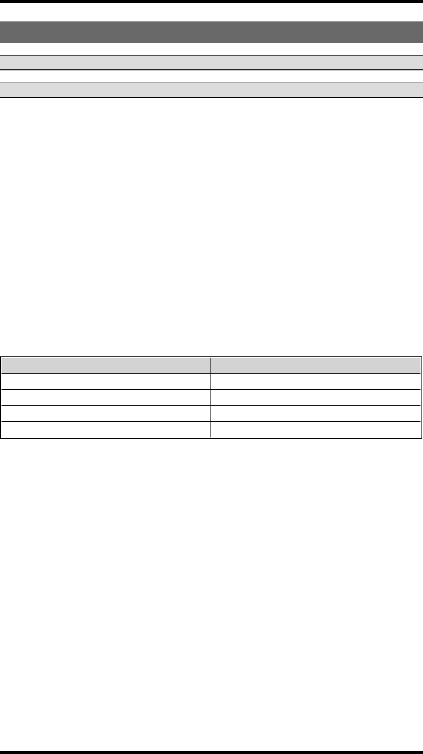
DIGITALINPUTS
The digital inputs on the receiver are connected to the transmitter LEDs. If you need to make other
settings for the digital inputs indications on the transmitter, please contact your representative for
assistance.
-44 -

Chapter 5: OPERATING MODES
CHAPTER 5: OPERATING MODES
SELECTOPERATINGMODE
NOTE! All receivers in this manual are intended to be customized. Contact your representative for
assistance.
-45 -

Chapter 6: LOAD SELECT MODES
CHAPTER 6: LOAD SELECT MODES
LOADSELECTMODE
NOTE! Before starting to perform these settings, make sure that the stop relays are deactivated!
1. Make sure that the stop button is pressed.
2.Twist and pull out the stop button.
The top LED lights (green when the battery capacity is good, red when the battery capacity is poor).
3. Press the right start button. Keep pressed.
4. Press the stop button.
5. Release the right start button.
The top LED flashes (green when the battery capacity is good, red when the battery capacity is poor)
when in menu mode.
6. Go to [Load select].
7. Select Load select mode and confirm by pressing the left start button.
-46 -
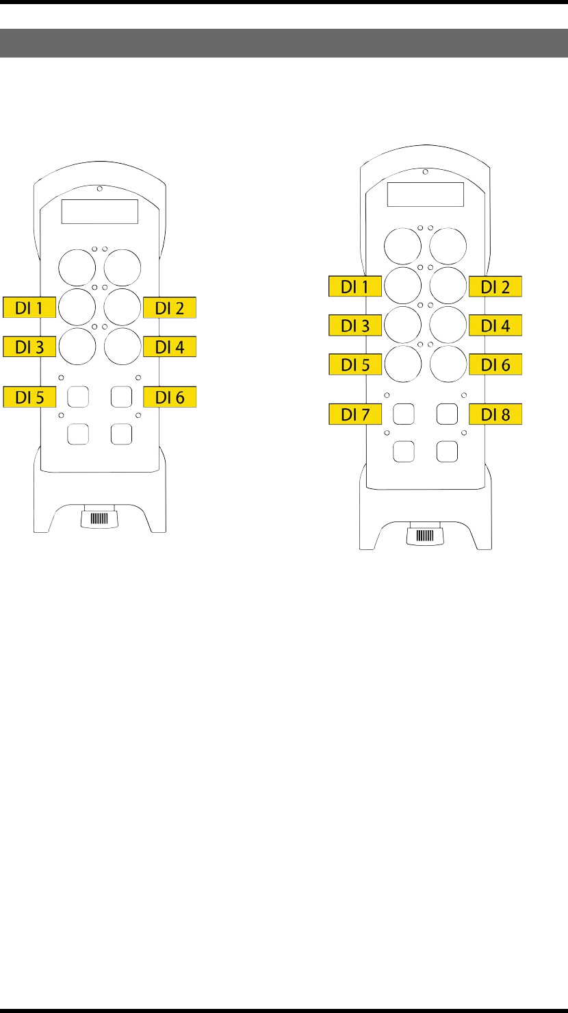
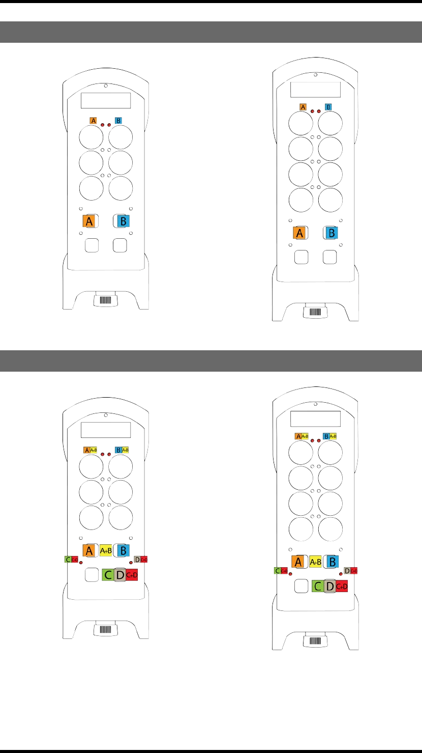
LOADSELECTMODE0
LOADSELECTMODE1
-47 -
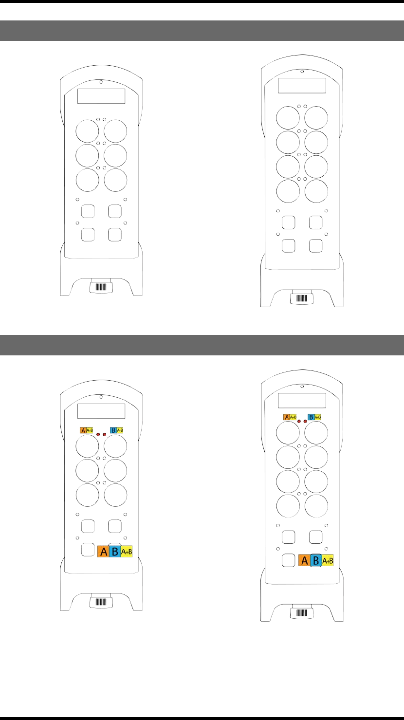
LOADSELECTMODE2
LOADSELECTMODE3
-48 -
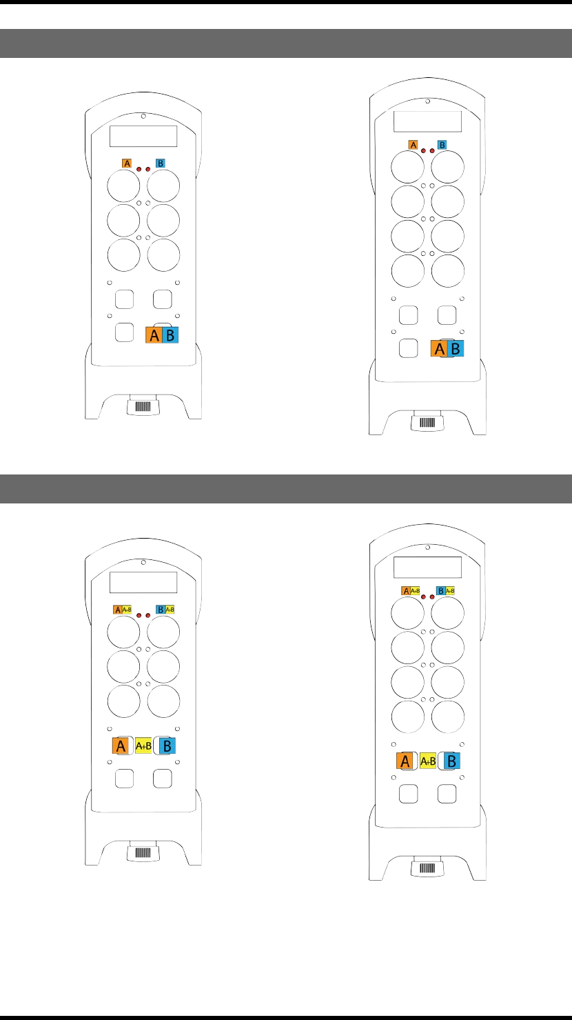
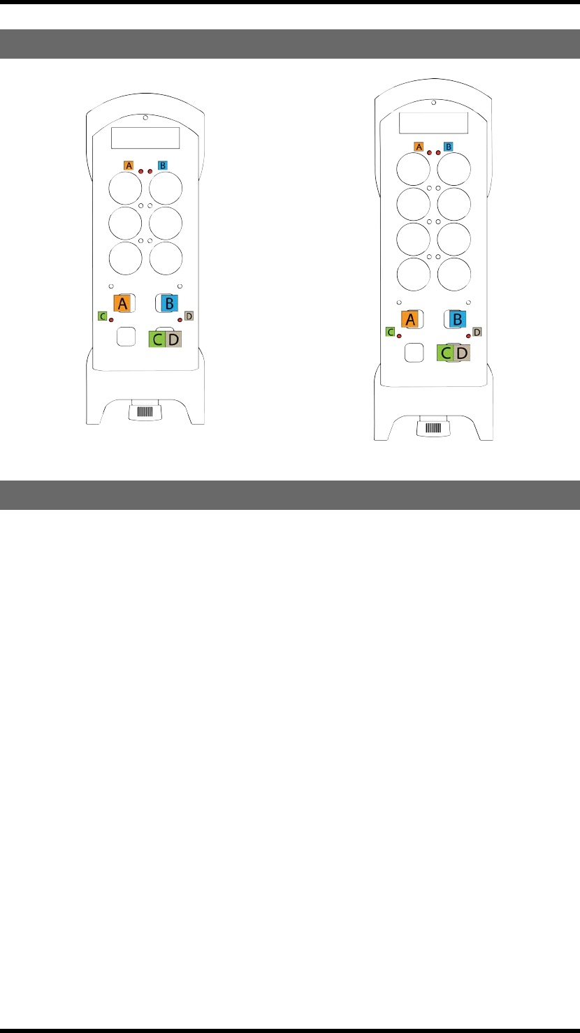
LOADSELECTMODE4
LOADSELECTMODE5
-49 -
LOADSELECTMODE6
LOADSELECTMODE7
The loads are selected in the PC program Settings manager. When you start the transmitter, you cannot
switch loads. The LEDs on the transmitter do not indicate which load is activated.
-50 -

Chapter 7: BATTERY GUIDE
CHAPTER 7: BATTERY GUIDE
BATTERYINFORMATION
TYPE OF BATTERY
TG-T14-4, TG-T14-5, TG-T14-6, TG-T14-7, TG-
T14-8, TG-T14-9, TG-T15-4, TG-T15-5, TG-
T15-6, TG-T15-7, TG-T15-8, TG-T15-9
Internal, rechargeable lithium-ion
battery
OPERATING TIME
TG-T14-4, TG-T14-5, TG-T14-6, TG-T14-7, TG-
T14-8, TG-T14-9, TG-T15-4, TG-T15-5, TG-
T15-6, TG-T15-7, TG-T15-8, TG-T15-9
Approx. 16 h with continuous usage
CHARGE
TG-T14-4, TG-T14-5, TG-T14-6, TG-T14-7, TG-
T14-8, TG-T14-9, TG-T15-4, TG-T15-5, TG-
T15-6, TG-T15-7, TG-T15-8, TG-T15-9
With a charger plug in the back of the transmitter
(see further description)
CHARGING TEMPERATURE
TG-T14-4, TG-T14-5, TG-T14-6, TG-T14-7, TG-
T14-8, TG-T14-9, TG-T15-4, TG-T15-5, TG-
T15-6, TG-T15-7, TG-T15-8, TG-T15-9
0° to 45°/ 32° to 113°
-51 -
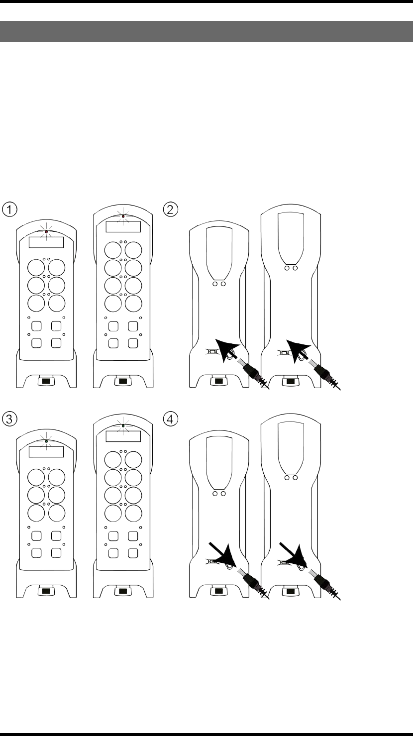
CHARGETHEBATTERY
1. When approximately 10 % of the battery capacity remains, the internal buzzer beeps 3 times and the
top LED lights red. If the transmitter has a display, the display monitors the battery status.
2. Put the charger plug into the socket in the back of the transmitter. While charging, the top LED
flashes in red. If the transmitter has an external battery, you can also remove the battery and charge it in
the Tele Radio 5V DC charging unit.
3. When fully charged, the top LED lights green.
4. Remove the charger plug.
-52 -

BATTERYPRECAUTIONS
Observe the following general battery warnings:
nAs batteries contains flammable substances such as lithium or other organic solvents, they may
cause heating, rupture or ignition.
nRisk of explosion if battery is replaced with a battery of an incorrect type.
nDo not short circuit, disassemble, deform or heat batteries.
nNever try to charge a visibly damaged or frozen battery.
nKeep batteries out of reach of small children. Should a child swallow a battery, consult a phys-
ician immediately.
nAvoid direct soldering to batteries.
nWhen discarding batteries, insulate the + and - terminals of batteries with insulating/ masking
tape. Do not put multiple batteries in the same plastic bag.
nWhen improperly disposed, lithium batteries may short circuit, causing them to become hot,
burst or ignite.
nStore in a cool location. Keep batteries away from direct sunlight, high temperature, and high
humidity.
nDo not throw batteries into fire.
REMOVAL/DISPOSALOFINTERNALBATTERY
NOTE! Electronics and batteries must be physically separated before disposal. Make sure that
electronics or batteries are not thrown in the household waste.
1. Remove the clip. Use a screwdriver to unscrew the screws.
2. Remove the rubber cover by hand.
3. Use a screwdriver to unscrew the screws in the back of the transmitter. Remove the front
encapsulation by hand. Turn the transmitter around, so that the buttons face up.
4. Use a screwdriver to unscrew the screw in the middle of the circuit board. Lift the circuit board up by
hand.
5. The battery pack is placed behind the circuit board. Remove the battery by hand.
ROHSANDWEEE
In accordance with Directive 2011/65/EU on restriction of the use of certain hazardous substances in
electrical and electronic equipment (RoHS) and Directive 2012/19/EU on waste electrical and
electronic equipment (WEEE), Tele Radio AB strives to minimize the use of hazardous materials,
promotes reuse and recycling, and reduces emissions to air, soil and water. When a commercially viable
alternative is available, Tele Radio AB strives to restrict or eliminate substances and materials that pose
an environmental, health or safety risk.
-53 -

GUARANTEE,SERVICE,REPAIRSANDMAINTENANCE
The Tele Radio AB products are covered by a guarantee/warranty against material, construction and
manufacturing faults. During the guarantee/warranty period, Tele Radio AB may replace the product or
faulty parts. Work under guarantee/warranty must be carried out by Tele Radio AB or by an authorized
service centre specified by Tele Radio AB.
This is not covered by the guarantee/ warranty:
nFaults resulting from normal wear and tear
nParts of a consumable nature
nProducts that have been subject to unauthorized modifications
nFaults resulting from incorrect installation and use
nDamp and water damage
Maintenance:
nRepairs and maintenance must be carried out by qualified personnel
nUse spare parts from Tele Radio AB only
nContact your representative if you require service or other assistance
nKeep the product in a dry, clean place
nKeep contacts and antennas clean
nWipe off dust using a slightly damp, clean cloth
WARNING! Never use cleaning solutions or high-pressure water.
-54 -

Chapter 8: CERTIFICATIONS CHAPTER
CHAPTER 8: CERTIFICATIONS CHAPTER
FCC/IC
FCCSTATEMENT
Statement for warning:
To satisfy FCC RF exposure requirements, a separation distance of 20 cm or more should be maintained
between the antenna of this device and persons during device operation.
To ensure compliance, operations at closer than this distance is not recommended.
Les antennes installées doivent être situées de facon à ce que la population ne puisse y être exposée à
une distance de moin de 20 cm. Installer les antennes de facon à ce que le personnel ne puisse
approcher à 20 cm ou moins de la position centrale de l' antenne.
La FCC des éltats-unis stipule que cet appareil doit être en tout temps éloigné d'au moins 20 cm des
personnes pendant son functionnement.
Caution: The user is cautioned that changes or modifications not expressly approved by the party
responsible for compliance could void the user's authority to operate the equipment.
This device complies with Industry Canada licence-exempt RSS standard(s) and Part 15 of the FCC
Rules. Operation is subject to the following two conditions:
(1) this device may not cause harmful interference, and
(2) this device must accept any interference received, including interference that may cause undesired
operation.
Le présent appareil est conforme aux CNR d'Industrie Canada applicables aux appareils radio exempts
de licence et la partie 15 des Règles FCC. L'exploitation est autorisée aux deux conditions suivantes :
(1) l'appareil ne doit pas produire de brouillage, et
(2) l'utilisateur de l'appareil doit accepter tout brouillage radioélectrique subi, même si le brouillage est
susceptible d'en compromettre le fonctionnement.
This equipment complies with FCC and IC radiation exposure limits set forth for an uncontrolled
environment. End user must follow the specific operating instructions for satisfying RF exposure
compliance. This transmitter must not be co-located or operating in conjunction with any other antenna
or transmitter.
Cet appareil est conforme aux limites d’exposition au rayonnement RF stipulées par la FCC et l’IC pour
une utilisation dans un environnement non contrôlé. L'utilisateur final doit suivre les instructions de
fonctionnement spécifiques pour le respect d'exposition aux RF. Lesémetteurs ne doivent pas être
placées près d’autres antennes ou émetteurs ou fonctionner avec ceux-ci.
Note: this equipment has been tested and found to comply with the limits for a class b digital device,
pursuant to part 15 of the FCC rules. These limits are designed to provide reasonable protection against
harmful interference in a residential installation. This equipment generates, uses and can radiate radio
frequency energy and, if not installed and used in accordance with the instructions, may cause harmful
interference to radio communications. However, there is no guarantee that interference will not occur
in a particular installation. If this equipment does cause harmful interference to radio or television
reception, which can be determined by turning the equipment off and on, the user is encouraged to try
to correct the interference by one or more of the following measures:
—reorient or relocate the receiving antenna.
—increase the separation between the equipment and receiver.
—connect the equipment into an outlet on a circuit different from that to which the receiver is
connected.
—consult the dealer or an experienced radio/TV technician for help.
-55 -

Chapter 8: CERTIFICATIONS CHAPTER
The radio module in this product is labelled with its own FCC ID and IC number. The FCC ID and IC is
not visible when the radio module is installed inside another device. Therefore, the outside of the device
into which the module is installed must also display a label referring to the radio module. The final end
device must be labelled in a visible area with the following:
“Contains FCC ID: ONFC1104B”
“Contains IC: 4807A-C1104B”
or
“Contains FCC ID: ONFC1108A”
“Contains IC: 4807A-C1108A”
or
“Contains FCC ID: ONFC1203A”
“Contains IC: 4807A-C1203A”
or
“Contains FCC ID: ONFC1203B”
“Contains IC: 4807A-C1203B"
or
“Contains FCC ID: ONFC1406A”
“Contains IC: 4807A-C1406A"
Under Industry Canada regulations, this radio transmitter may only operate using an antenna of a type
and maximum (or lesser) gain approved for the transmitter by Industry Canada. To reduce potential
radio interference to other users, the antenna type and its gain should be so chosen that the equivalent
isotropically radiated power (e.i.r.p.) is not more than that necessary for successful communication.
Conformément à la réglementation d'Industrie Canada, le présent émetteur radio peut fonctionner avec
une antenne d'un type et d'un gain maximal (ou inférieur) approuvé pour l'émetteur par Industrie
Canada. Dans le but de réduire les risques de brouillage radioélectrique à l'intention des autres
utilisateurs, il faut choisir le type d'antenne et son gain de sorte que la puissance isotrope rayonnée
équivalente (p.i.r.e.) ne dépasse pas l'intensité nécessaire à l'établissement d'une communication
satisfaisante.
This radio transmitter has been approved by Industry Canada to operate with the antenna types listed
below with the maximum permissible gain and required antenna impedance for each antenna type
indicated. Antenna types not included in this list, having a gain greater than the maximum gain indicated
for that type, are strictly prohibited for use with this device.
Gain of antenna: 3.0dBi max.
Type of antenna: 50ohm, Omni-directional
Le présent émetteur radio a été approuvé par Industrie Canada pour fonctionner avec les types
d'antenne énumérés ci-dessous et ayant un gain admissible maximal et l'impédance requise pour chaque
type d'antenne.
Les types d'antenne non inclus dans cette liste, ou dont le gain est supérieur au gain maximal indiqué,
sont strictement interdits pour l'exploitation de l'émetteur.
Gain d'antenne: 3.0dBi maximal
Type d'antenne: 50 ohm, Omni-directionnel
-56 -

THERADIOMODULE
Each radio module is specifically designed to match a Tele Radio product in terms of physical
dimensions, connection points, voltage levels, signal interface etc. To use the radio modules in non Tele
Radio products is not permitted. The radio modules are designed to interface directly to the main board
of the receiver/transmitter unit. They are power supplied by the main board and the radio circuit
operates strictly according to instructions from a microprocessor on the main board. The radio circuit
configuration is stored in a flash memory on the radio module. A receiver/transmitter unit with a
defective/no radio module will give an error message immediately after power up, and it will not be
possible to start a radio session.
RADIOMODULELIST
The products in this instruction contain the radio modules:
D00005-05 TG-RX-MNRCAN, TG-RX-MNRANA, TG-RX-
MNRJ1939
D00005-06 TG-T14-8, TG-T15-8
D00005-07 TG-RX-MNPCAN, TG-RX-MNPANA, TG-RX-
MNPJ1939
D00005-09 TG-T14-9, TG-T15-9
D00007-03 TG-T14-8, TG-T15-8, TG-T14-9, TG-T15-9
-57 -
PRODUCTLABELONTHERECEIVER
You will find the product label on the outside of the enclosure of the receiver.
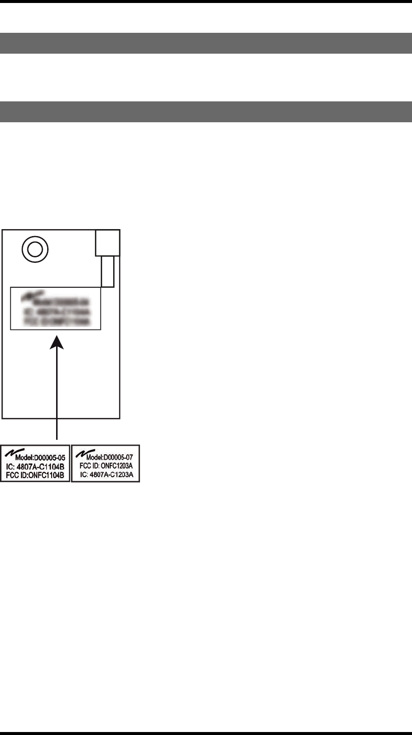
FCC/ICLABELINTHERECEIVER
The FCC/IC label is placed on the radio module. The radio module is mounted inside the receiver.
D00005-5: TG-RX-MNRCAN, TG-RX-MNRANA, TG-RX-MNRJ1939
D00005-7: TG-RX-MNPCAN, TG-RX-MNPANA, TG-RX-MNPJ1939
-58 -
PRODUCTLABELONTHETRANSMITTER
You will find the product label in the back of the transmitter.
-59 -
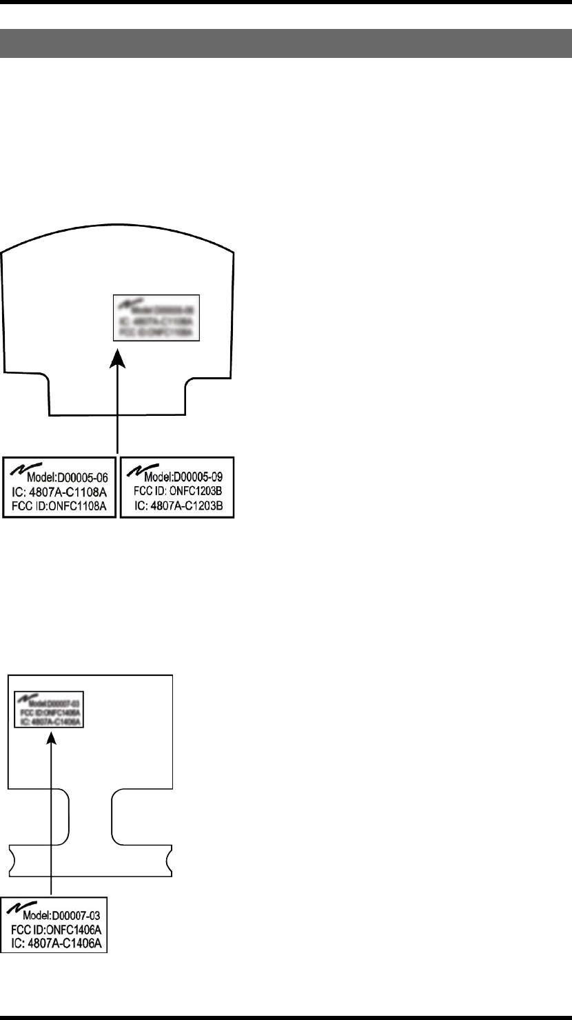
FCC/ICLABELINTHETRANSMITTER
The FCC/IC label is placed on the radio module. The radio module is mounted inside the transmitter.
D00005-06:
TG-T14-8, TG-T15-8
D00005-09:
TG-T14-9, TG-T15-9
The FCC/IC label is placed on the main board. The main board is mounted inside the transmitter.
D00007-03:
TG-T14-8, TG-T15-8, TG-T14-9, TG-T15-9
-60 -
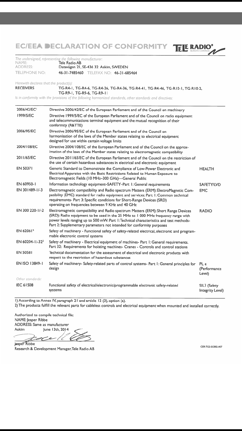
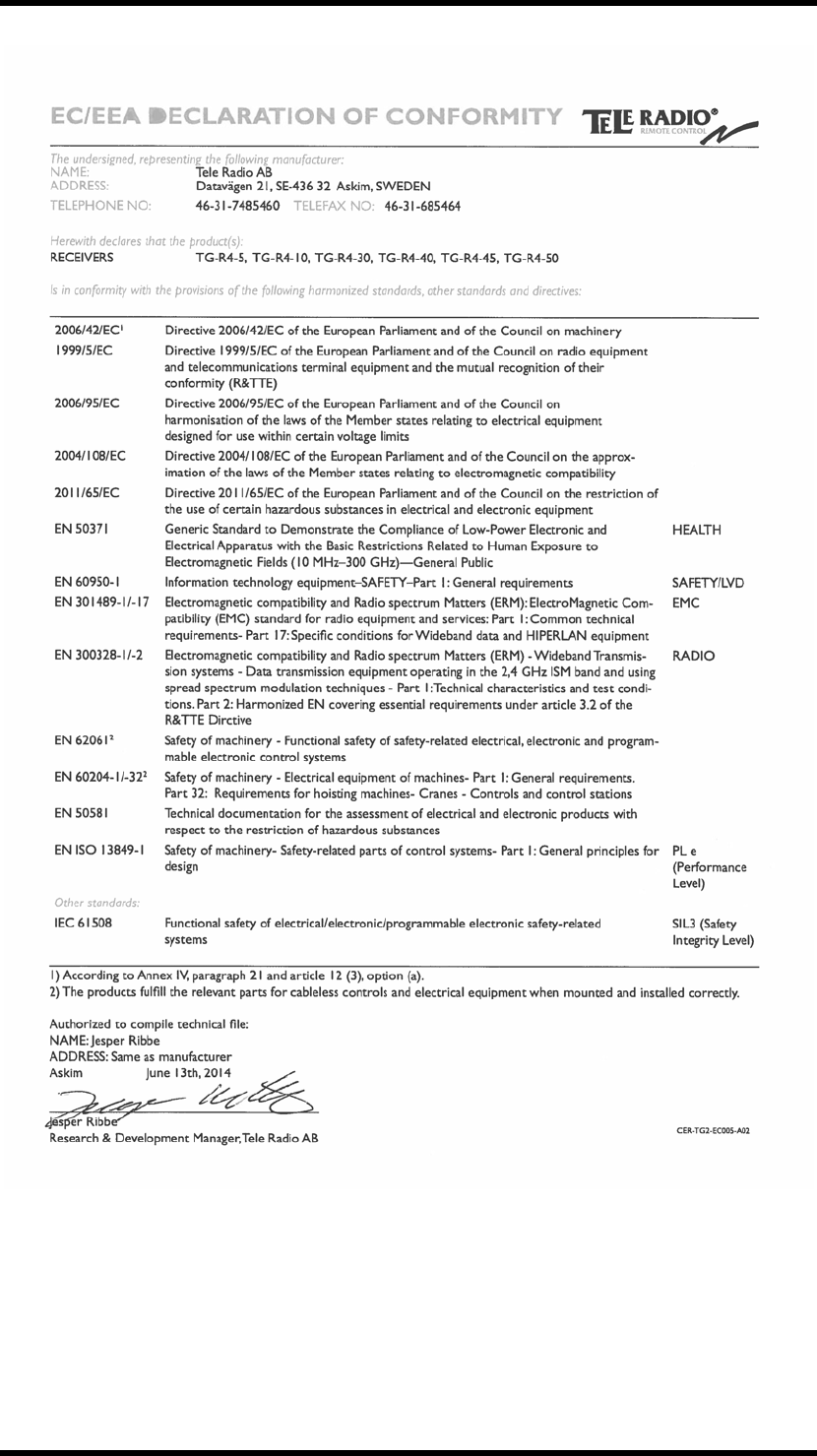
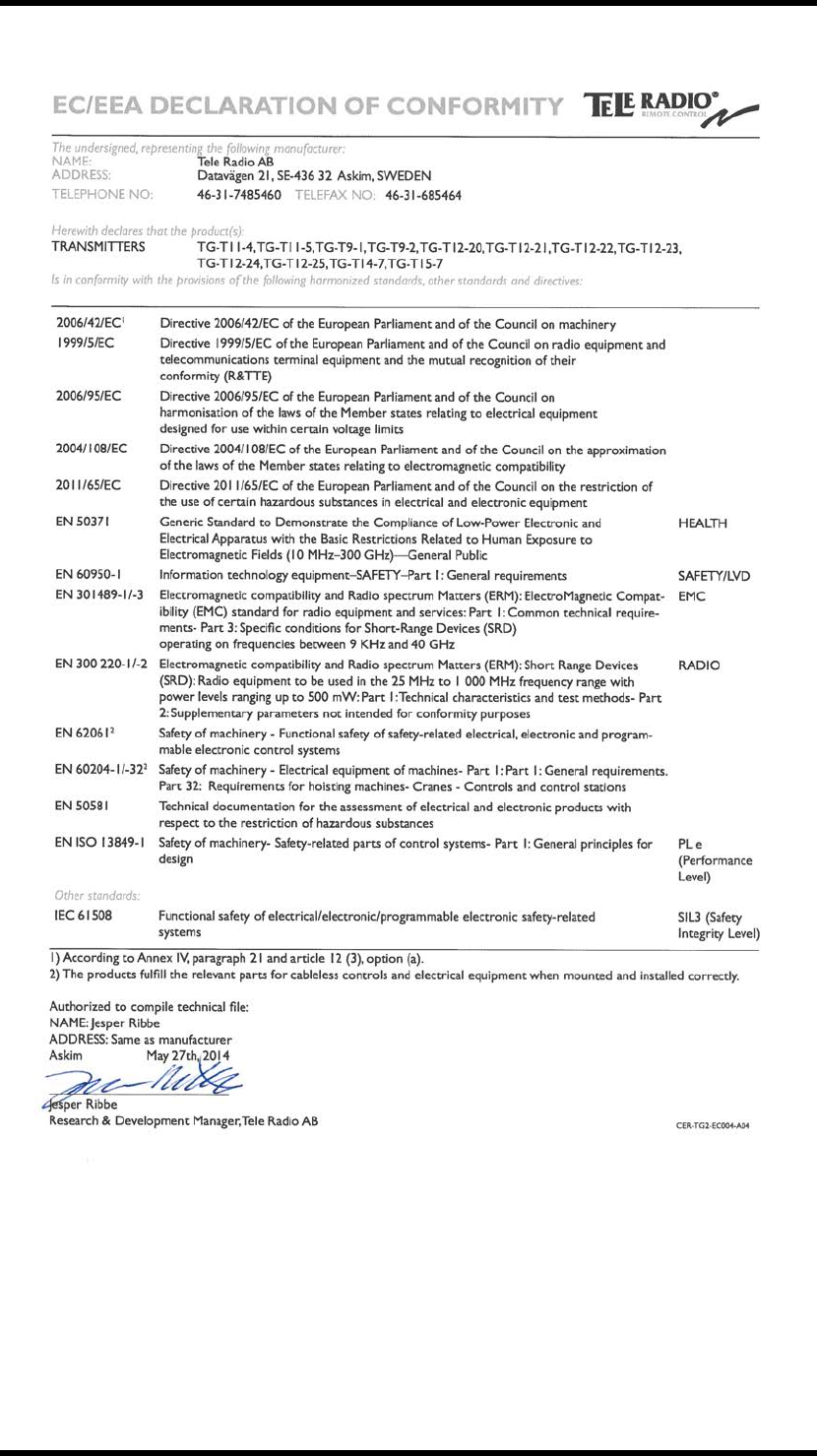
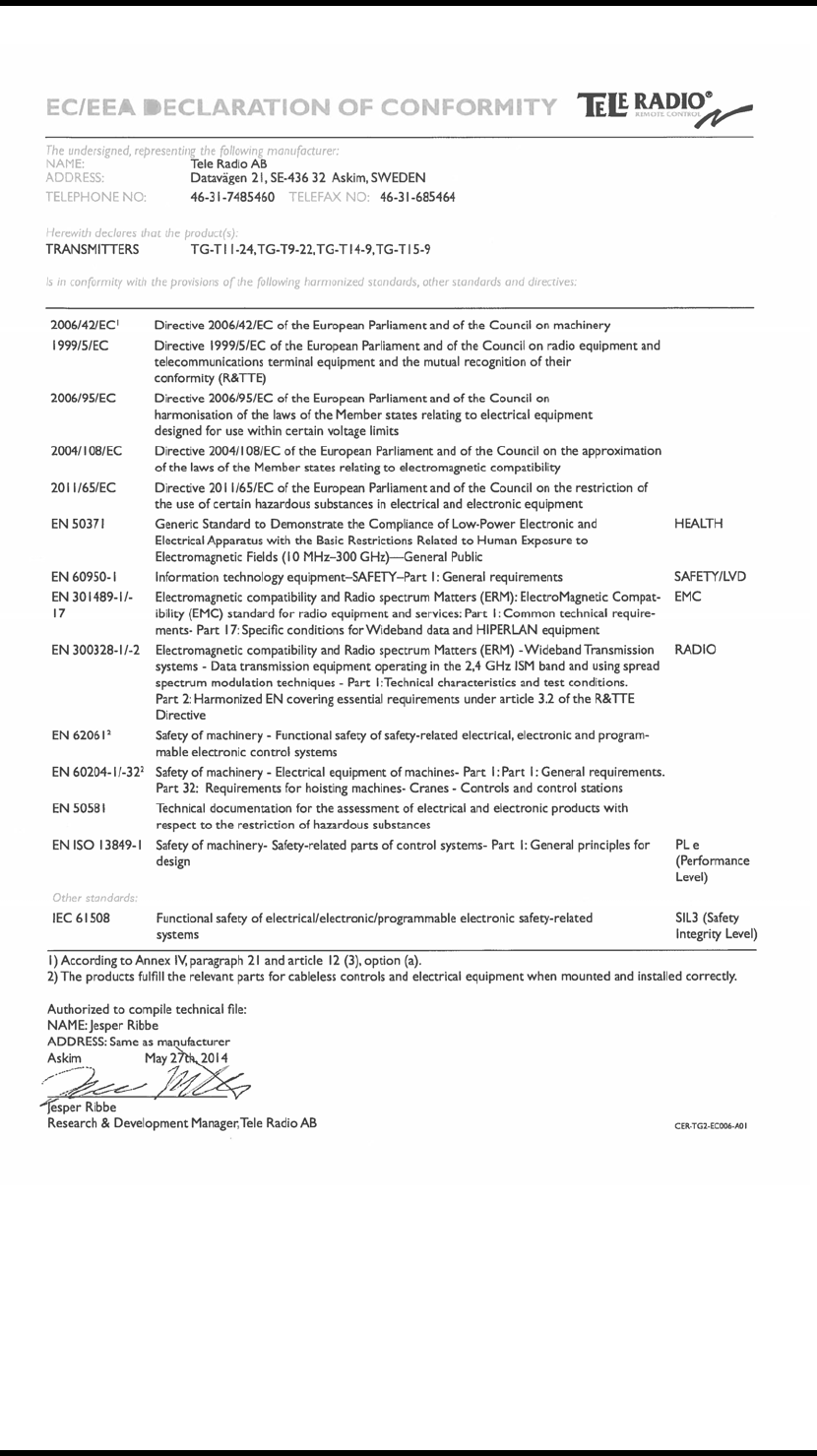
EC/EEADECLARATIONOFCONFORMITY
-61 -
-62 -
-63 -
-64 -

(THISPAGEHASBEENINTENTIONALLYLEFTBLANK)
-65 -