Tele Radio C1409A Transmitter User Manual
Tele Radio AB Transmitter
UserManual.wiki
>
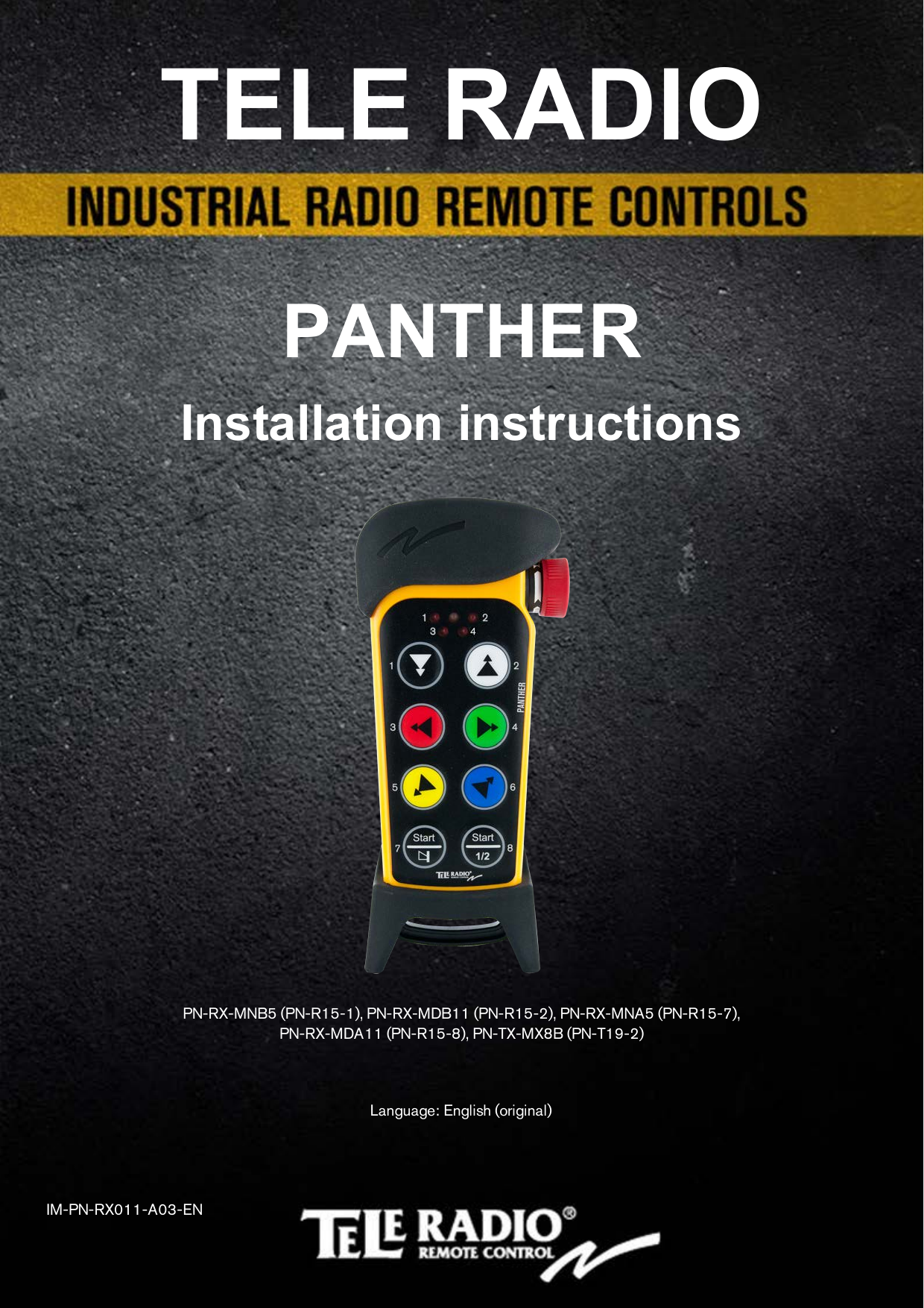
Tele Radio
>
C1409A User Manual
User manual
Navigation menu
Upload a User Manual
Namespaces
Wiki Guide
HTML
PDF
Info
Views
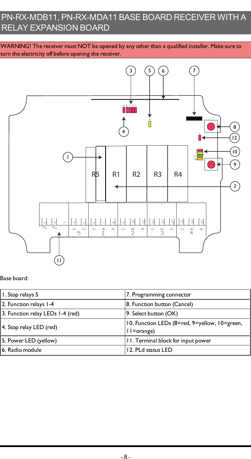
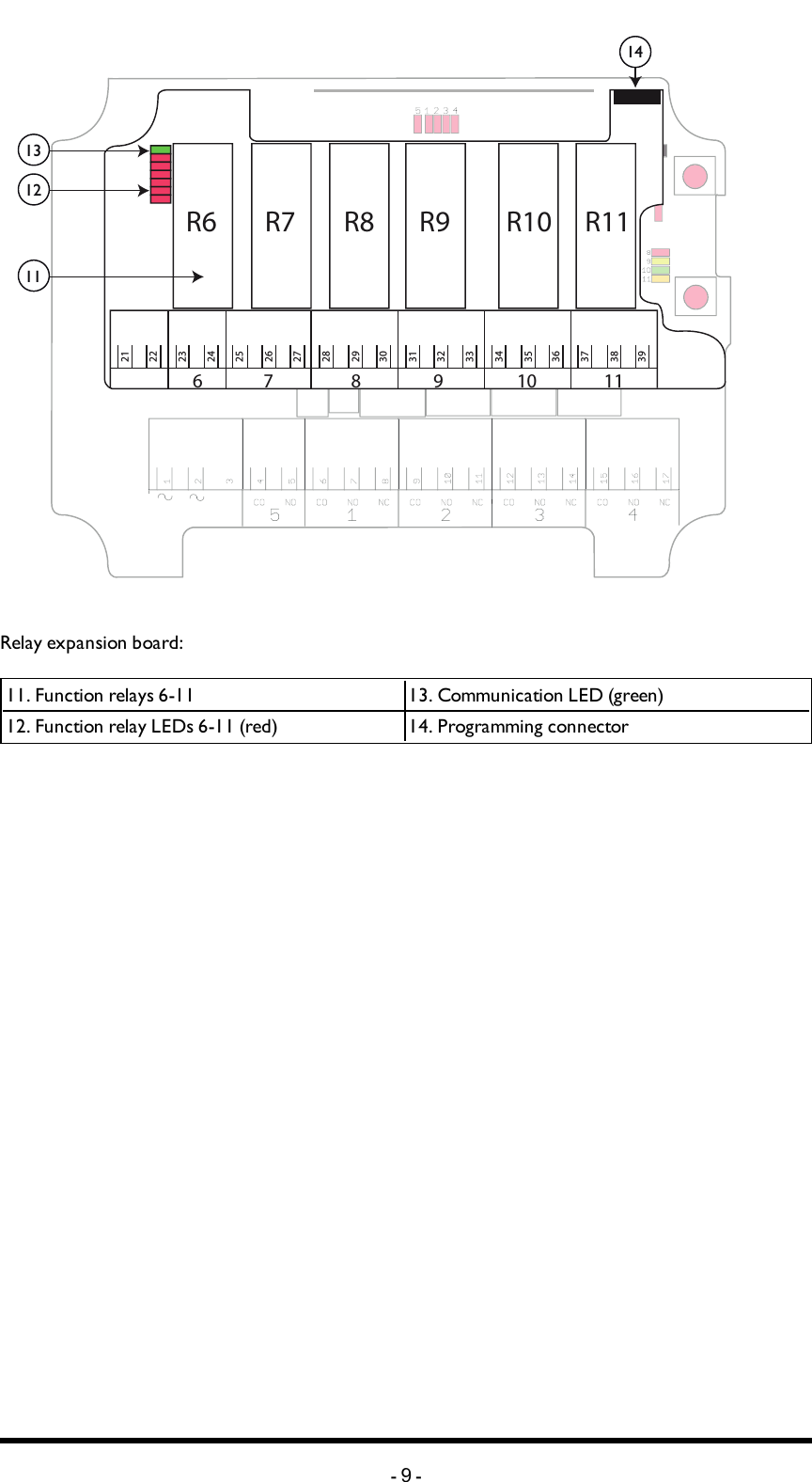
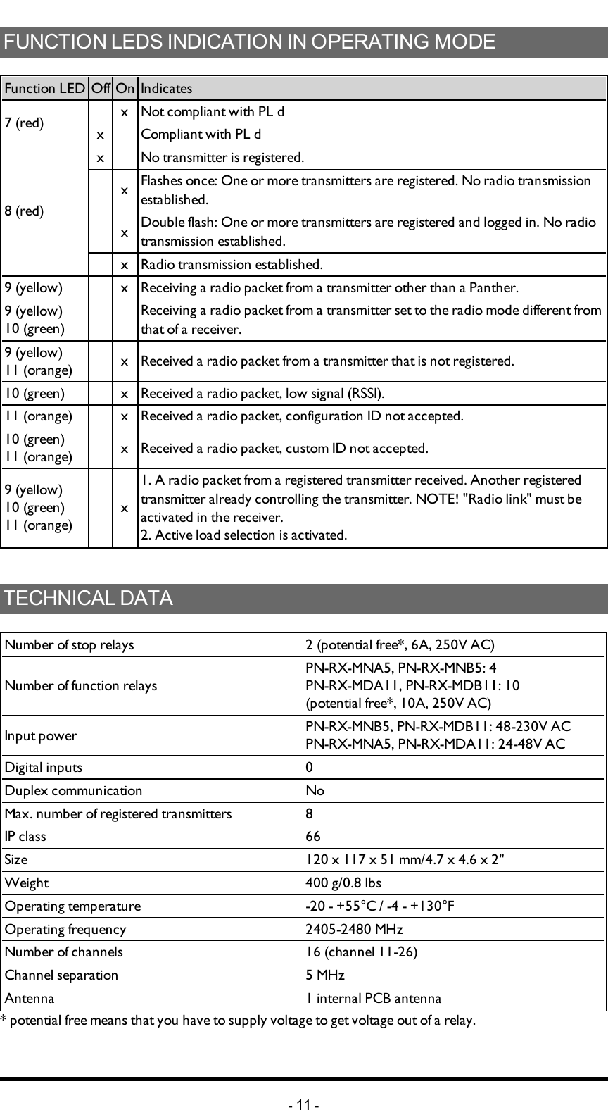
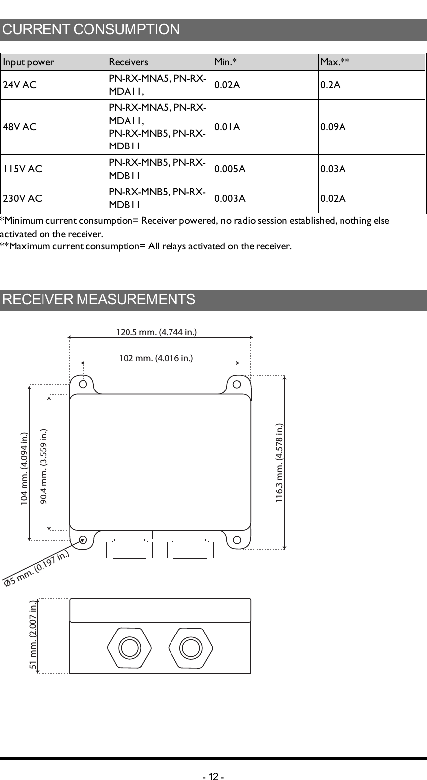
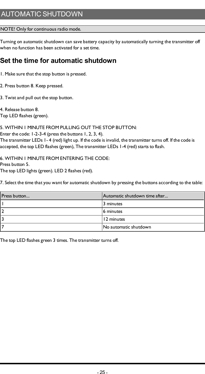
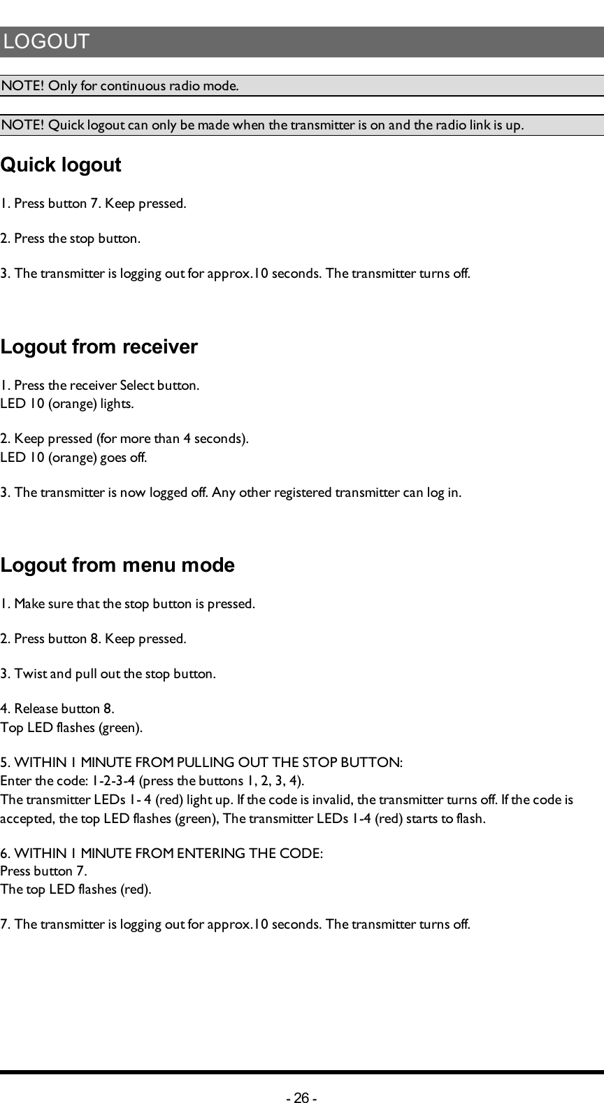
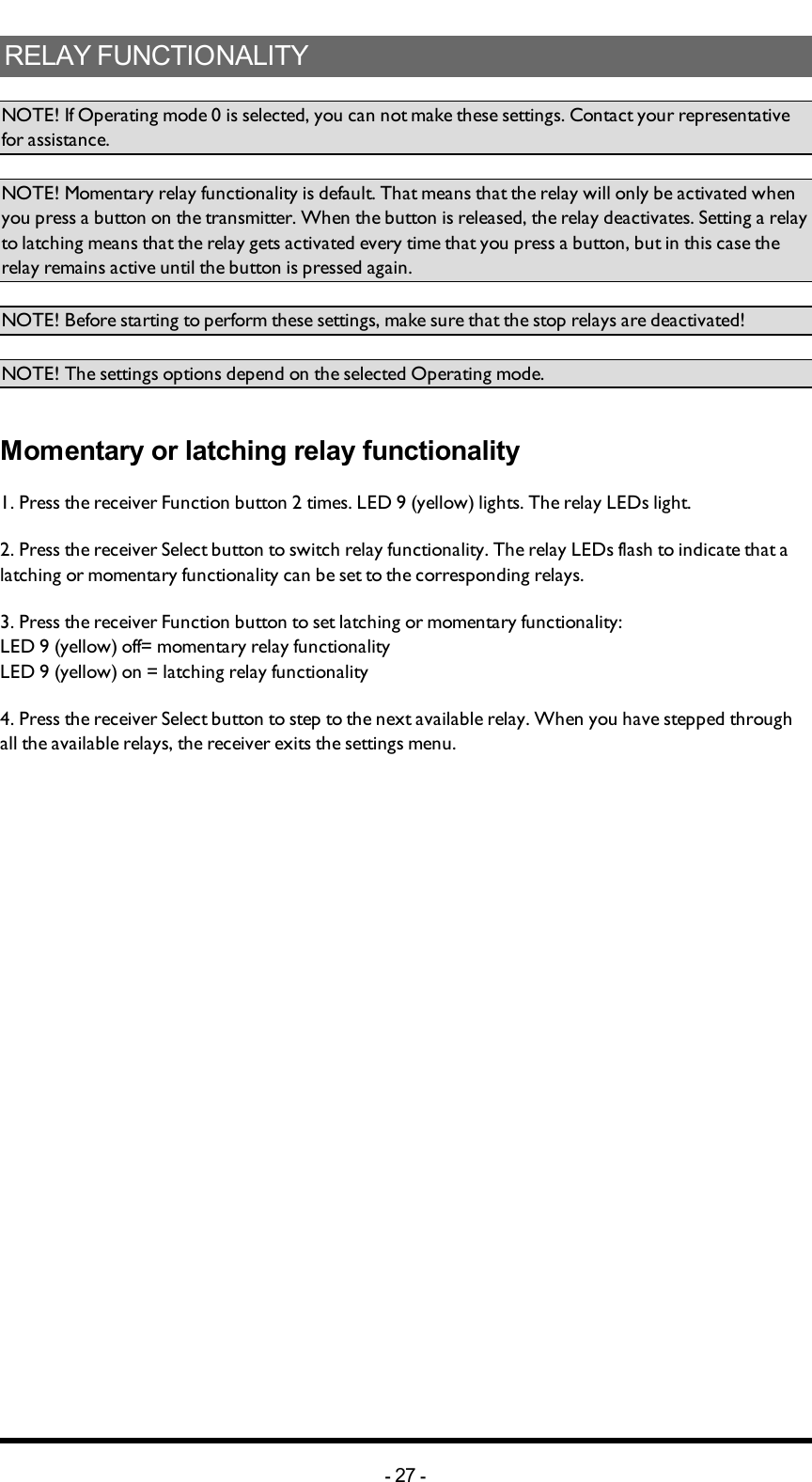
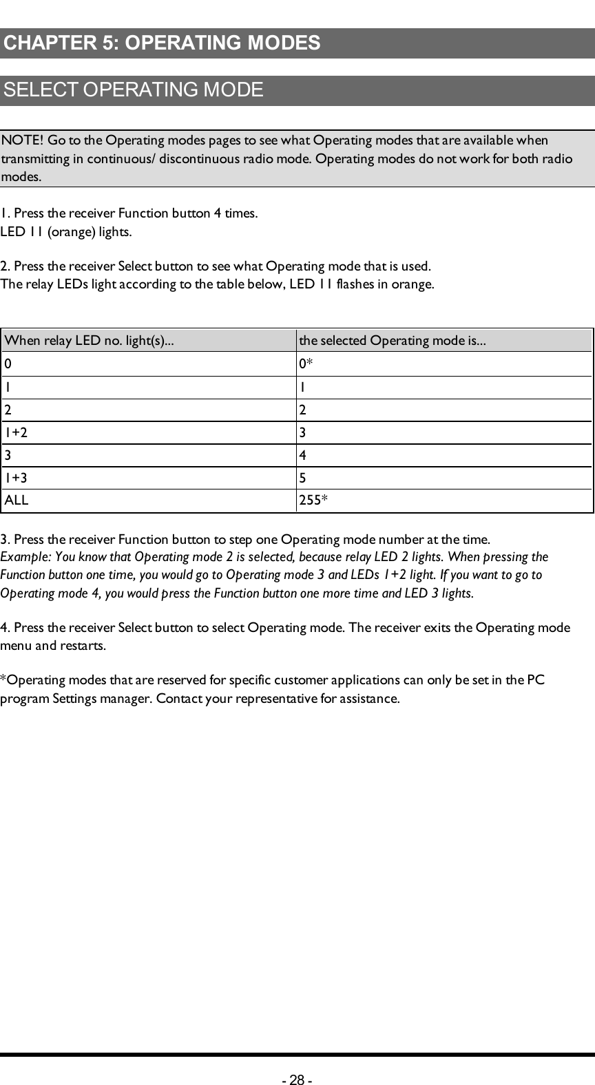
User Manual
Discussion / Help
Navigation