Tele Radio C1409A Transmitter User Manual
Tele Radio AB Transmitter
User manual
TELE RADIO
PANTHER
Installation instructions
PN-RX-MNB5 (PN-R15-1), PN-RX-MDB11 (PN-R15-2), PN-RX-MNA5 (PN-R15-7),
PN-RX-MDA11 (PN-R15-8), PN-TX-MX8B (PN-T19-2)
Language: English (original)
IM-PN-RX011-A03-EN

CONTENTS
Chapter 1: CUSTOMER INFORMATION 1
Chapter 2: FUNCTIONAL SAFETY 3
Chapter 3: PRODUCT PAGES 5
PN-RX-MNB5, PN-RX-MNA5 Base board receiver 5
PN-RX-MDB11, PN-RX-MDA11 Base board receiver with a Relay expansion board 8
PN-TX-MX8B Transmitter 13
Chapter 4: INSTALLERS GUIDE 17
Default radio mode 17
Switchradio mode in the transmitter 17
Start the transmitter 18
Start the transmitter in menu mode 18
Register the transmitter in the receiver 19
Erase all transmitters from the receiver 21
Turn the transmitter off 21
Replace 21
Frequencies and channels 23
Automatic shutdown 25
Logout 26
Relay functionality 27
Chapter 5: OPERATING MODES 28
Chapter 6: LOAD SELECT MODES 34
Chapter 7: BATTERY GUIDE 38
Chapter 8: CERTIFICATIONS CHAPTER 41
-2-

Chapter 1: CUSTOMER INFORMATION
CHAPTER 1: CUSTOMER INFORMATION
THANK YOU FOR PURCHASING A TELE RADIO AB PRODUCT
READALLINSTRUCTIONS ANDWARNINGS CAREFULLY BEFOREMOUNTING, INSTALLING
ANDCONFIGURATING THEPRODUCTS.
These instructions are published by Tele Radio AB without any guarantee. The instructions may be
removed or revised by Tele Radio AB at any time and without further notice. Corrections and additions
will be added to the latest version of the instruction.
IMPORTANT! These instructions are directed to installers. There are separate instructions directed
towards end users. The instructions that contain information on the installation and configuration of the
radio remote control unit on the machine are not intended to be passed on to the end user. Only such
information may be passed on to the end user that is needed to operate the machine correctly by radio
remote control.
Tele Radio AB products are covered by a guarantee/ warranty against material, construction or
manufacturing faults. During the guarantee/ warranty period, Tele Radio AB may replace the product or
faulty parts with new. Work under guarantee/ warranty must be carried out by Tele Radio AB or by an
authorized service center specified by Tele Radio AB. Contact your Tele Radio AB representative if you
need support or service.
©Tele Radio AB
Datavägen 21
SE-436 36 ASKIM
SWEDEN
Tel: +46-31-748 54 60
Fax: +46-31-68 54 64
www.tele-radio.com
-1-

WARNINGS & RESTRICTIONS
WARNING! Tele Radio remote controls are often built into wider applications. We recommend that
the system is provided with a wired emergency stop where necessary.
NOTE! We recommend that the functionality of the stop button is being tested at a regular basis: At a
minimum, when used for 200 hours. Test the stop button by pressing it and pulling it out.
INSTALLING, CONNECTING AND MOUNTING
nAllow only licensed or qualified personnel to install the product.
nSwitch the power supply off to the receiver before connecting the equipment.
nCheck that you have connected the power supply to the correct connection terminal.
nTo utilize the safety of the system, use the stop relays in the safety circuitry of the object that you
want to control.
nUse undamaged cables. No cables should hang loose.
nAvoid installing in areas affected by strong vibrations.
nPlace the receiver well away from wind, damp and water.
nCable glands and vent plugs must face down to prevent water from seeping in.
THE USER
nMake sure that the user is following the instructions.
nMake sure that the user has reached the certified age of your country to operate the equipment.
nMake sure that the user is not under the influence of drugs, alcohol and medicines.
nAllow only qualified personnel to have access to the transmitter and operate the equipment.
nMake sure that the user does not leave the transmitter unsupervised.
nMake sure that the user always turns the transmitter off when not in use.
nMake sure that the user keeps a good overview of the work area.
MAINTENANCE
nUse the stop button to start and turn off the transmitter as often as possible.
nWhen error messages are shown, it is very important to find out what caused them.
nIf the stop button is mechanically damaged, contact your representative for service immediately.
nAlways contact your representative for service and maintenance work on the product.
nWrite down the serial numbers/ ID codes of the receivers and transmitters used. This inform-
ation should be recorded on the “Settings document” for your product (download from our web-
site).
nAvoid registering transmitters to receivers where it is not being used.
nKeep the safety instruction for future reference. Always download the configurations instruction
from our web site for the latest version available.
-2-
Chapter 2: FUNCTIONAL SAFETY
CHAPTER 2: FUNCTIONAL SAFETY
FUNCTIONAL SAFETY
Safety function
The safety-related stop function in the radio system complies with EN 13849-1:2008 Category 3 PL d.
The stop relays on the receiver unit are controlled by the stop button on the transmitter unit. When the
stop button is pressed, the stop relays break the power to the safety-related application. The complete
end-user system, including the radio system, enters a safe state. The maximum response time for the
safety-related stop function is 500ms.
Applicable products
The following transmitter and receiver units are prepared to comply with the appointed safety
requirements:
PN-RX-MNB5 (PN-R15-1)
PN-RX-MDB11 (PN-R15-2)
PN-RX-MNA5 (PN-R15-7)
PN-RX-MDA11 (PN-R15-8)
PN-TX-MX8B (PN-T19-2)
NOTE! Both the receiver and the transmitter used in the specific end-user system must be compliant.
Installation
The stop relays on the receiver unit shall be correctly installed on the end-user system, so that
opened/deactivated stop relays break the power to the safety-related application. The safety level of the
stop function can only be credited when used in a complete end-user system which complies with EN
13849-1:2008 Category 3 PL d.
Configuration
The default configuration of the receiver unit complies with the appointed safety requirements. Any re-
configuration that oversteps the safety requirements will be indicated by a LED on the main board of the
receiver unit. Before commissioning the radio system, the installer must check the LED indication.
Function LED Status Indicates
PL d status LED (red) ON Not compliant with PL d
OFF Compliant with PL d
R1
R2
R5
R5
R5
R4
R3
1
2
R5
1. Stop relays
2. PL dstatus LED
-3-

Chapter 2: FUNCTIONAL SAFETY
WARNING!
All safety related parameters shall be configured in the following way in order to comply with the
appointed safety requirements:
nThe system shall be configured in continuous radio mode
nAll relays shall be switched off when the radio link is down
nThe radio link timeout shall be set to maximum 500ms
nThe login/logout function shall be activated
nCustom ID setting shall be deactivated, i.e. the receiver shall always use the unique transmitter
ID code
-4-
Chapter 3: PRODUCT PAGES
CHAPTER 3: PRODUCT PAGES
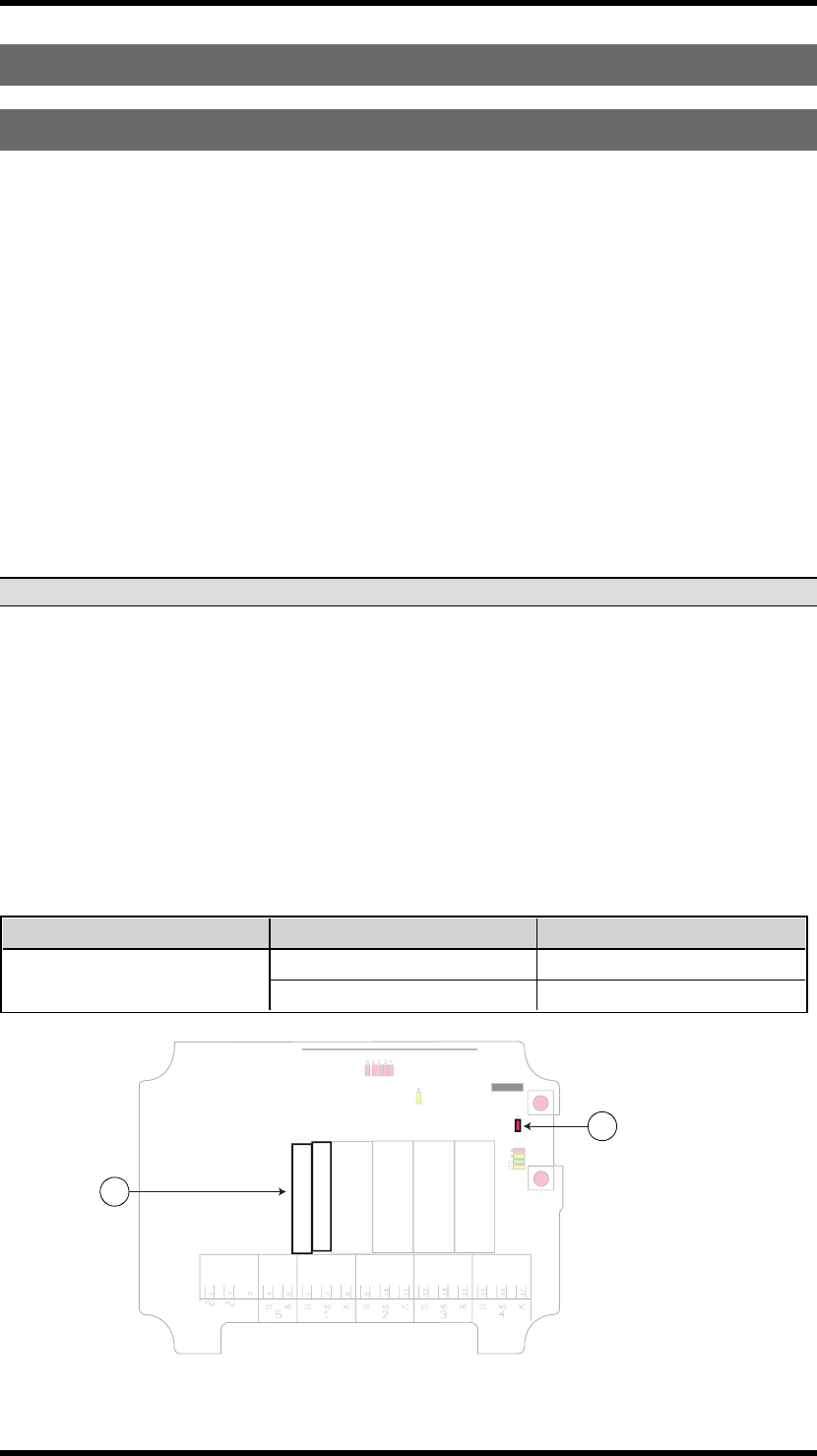
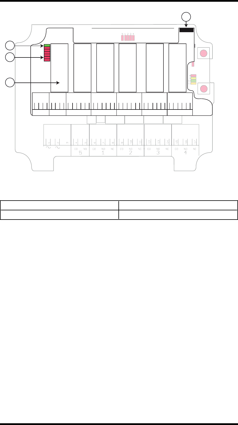
PN-RX-MNB5, PN-RX-MNA5 BASE BOARD RECEIVER
WARNING! The receiver must NOT be opened by any other than a qualified installer. Make sure to
turn the electricity off before opening the receiver.
Base board:
R1 R2R5 R4
R3
5
8
10
12
9
7
6
11
4
3
1
2
1. Stop relays 5 7. Programming connector
2. Function relays 1-4 8. Function button (Cancel)
3. Function relay LEDs 1-4 (red) 9. Select button (OK)
4. Stop relay LED (red) 10. Function LEDs (8=red, 9=yellow, 10=green,
11=orange)
5. Power LED (yellow) 11. Terminal block for input power
6. Radio module 12. PL d status LED
-5-

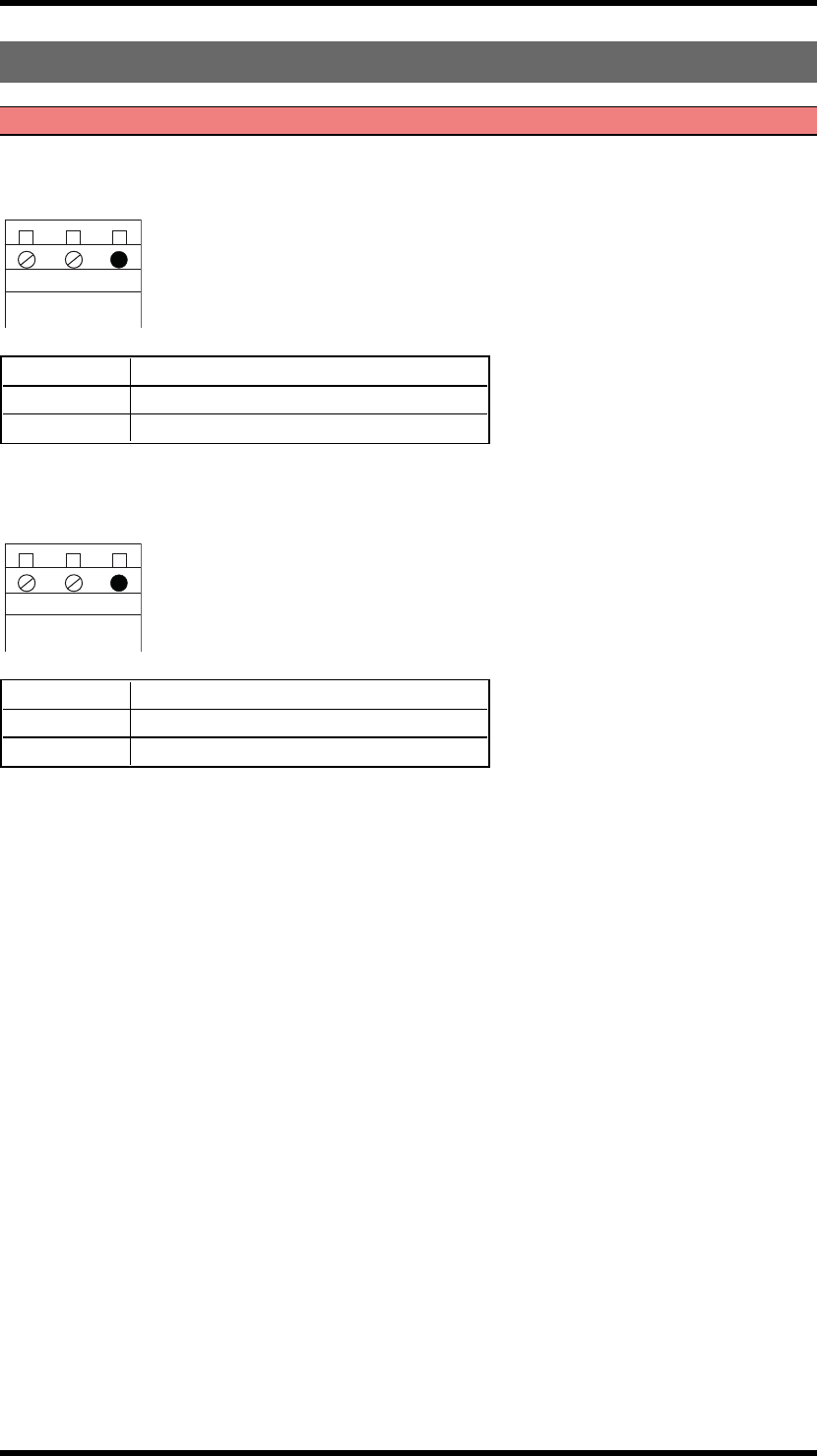
TERMINAL BLOCK FOR INPUT POWER ON BASE BOARD
WARNING! Make sure to connect the input power according to the tables below.
PN-RX-MNB5, PN-RX-MDB11
3
2
1
48 - 230V AC
1 48 - 230V AC
2 48 - 230V AC
3 Not used
PN-RX-MNA5, PN-RX-MDA11
3
2
1
24 - 48V AC
1 24 - 48V AC
2 24 - 48V AC
3 Not used
-6-

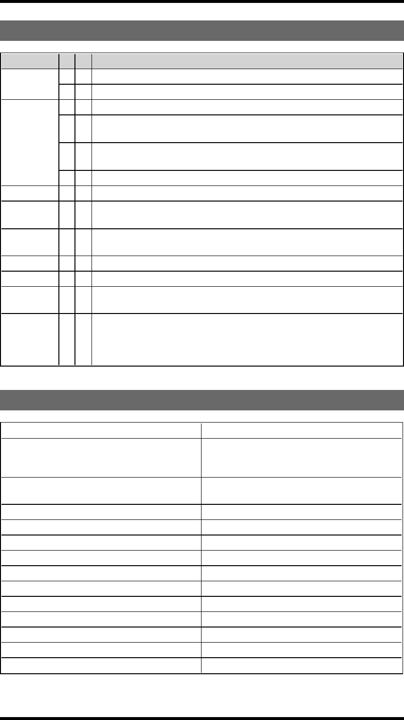
FUNCTION LEDS INDICATION IN OPERATING MODE
FunctionLED Off On Indicates
7 (red) x Not compliant with PL d
x Compliant with PL d
8 (red)
x No transmitter is registered.
x Flashes once: One or more transmitters are registered. No radio transmission
established.
x Double flash: One or more transmitters are registered and logged in. No radio
transmission established.
x Radio transmission established.
9 (yellow) x Receiving a radio packet from a transmitter other than a Panther.
9 (yellow)
10 (green) Receiving a radio packet from a transmitter set to the radio mode different from
that of a receiver.
9 (yellow)
11 (orange) x Received a radio packet from a transmitter that is not registered.
10 (green) x Received a radio packet, low signal (RSSI).
11 (orange) x Received a radio packet, configuration ID not accepted.
10 (green)
11 (orange) x Received a radio packet, custom ID not accepted.
9 (yellow)
10 (green)
11 (orange)
x
1. A radio packet from a registered transmitter received. Another registered
transmitter already controlling the transmitter. NOTE! "Radio link" must be
activated in the receiver.
2. Active load selection is activated.
-7-
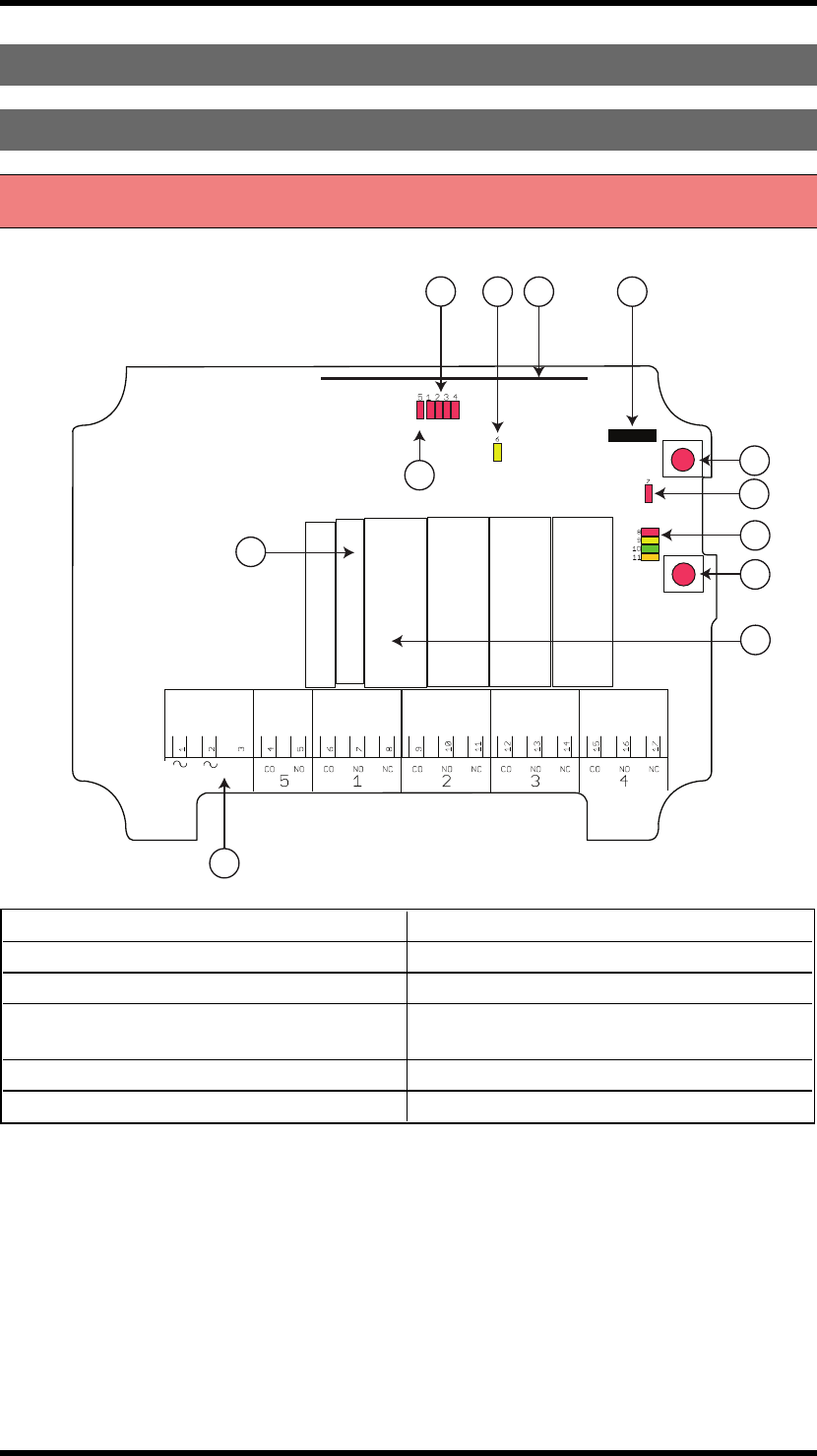
PN-RX-MDB11, PN-RX-MDA11 BASE BOARD RECEIVER WITH A
RELAY EXPANSION BOARD
WARNING! The receiver must NOT be opened by any other than a qualified installer. Make sure to
turn the electricity off before opening the receiver.
R1 R2R5 R4
R3
5
8
10
12
9
7
6
11
4
3
1
2
Base board:
1. Stop relays 5 7. Programming connector
2. Function relays 1-4 8. Function button (Cancel)
3. Function relay LEDs 1-4 (red) 9. Select button (OK)
4. Stop relay LED (red) 10. Function LEDs (8=red, 9=yellow, 10=green,
11=orange)
5. Power LED (yellow) 11. Terminal block for input power
6. Radio module 12. PLd status LED
-8-
R1
R2
R5
R5
R5
R5
R4
R3
R9 R11R10R8R7R6
678 9 10 11
21
22
23
24
25
26
27
28
29
30
31
32
33
34
35
36
37
38
39
11
14
12
13
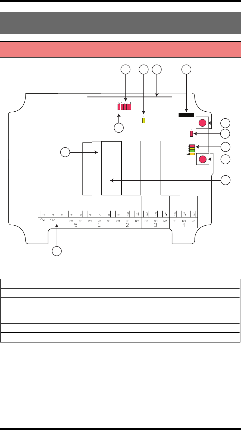
Relay expansion board:
11. Function relays 6-11 13. Communication LED (green)
12. Function relay LEDs 6-11 (red) 14. Programming connector
-9-
TERMINAL BLOCK FOR INPUT POWER ON BASE BOARD
WARNING! Make sure to connect the input power according to the tables below.
PN-RX-MNB5, PN-RX-MDB11
3
2
1
48 - 230V AC
1 48 - 230V AC
2 48 - 230V AC
3 Not used
PN-RX-MNA5, PN-RX-MDA11
3
2
1
24 - 48V AC
1 24 - 48V AC
2 24 - 48V AC
3 Not used
-10 -
FUNCTION LEDS INDICATION IN OPERATING MODE
FunctionLED Off On Indicates
7 (red) x Not compliant with PL d
x Compliant with PL d
8 (red)
x No transmitter is registered.
x Flashes once: One or more transmitters are registered. No radio transmission
established.
x Double flash: One or more transmitters are registered and logged in. No radio
transmission established.
x Radio transmission established.
9 (yellow) x Receiving a radio packet from a transmitter other than a Panther.
9 (yellow)
10 (green) Receiving a radio packet from a transmitter set to the radio mode different from
that of a receiver.
9 (yellow)
11 (orange) x Received a radio packet from a transmitter that is not registered.
10 (green) x Received a radio packet, low signal (RSSI).
11 (orange) x Received a radio packet, configuration ID not accepted.
10 (green)
11 (orange) x Received a radio packet, custom ID not accepted.
9 (yellow)
10 (green)
11 (orange)
x
1. A radio packet from a registered transmitter received. Another registered
transmitter already controlling the transmitter. NOTE! "Radio link" must be
activated in the receiver.
2. Active load selection is activated.
TECHNICAL DATA
Number of stop relays 2 (potential free*, 6A, 250V AC)
Number of function relays
PN-RX-MNA5, PN-RX-MNB5: 4
PN-RX-MDA11, PN-RX-MDB11: 10
(potential free*, 10A, 250V AC)
Input power PN-RX-MNB5, PN-RX-MDB11: 48-230V AC
PN-RX-MNA5, PN-RX-MDA11: 24-48V AC
Digital inputs 0
Duplex communication No
Max. number of registered transmitters 8
IP class 66
Size 120 x 117 x 51 mm/4.7 x 4.6 x 2"
Weight 400 g/0.8 lbs
Operating temperature -20 - +55°C / -4 - +130°F
Operating frequency 2405-2480 MHz
Number of channels 16 (channel 11-26)
Channel separation 5 MHz
Antenna 1 internal PCB antenna
* potential free means that you have to supply voltage to get voltage out of a relay.
-11 -
CURRENT CONSUMPTION
Input power Receivers Min.* Max.**
24V AC PN-RX-MNA5, PN-RX-
MDA11, 0.02A 0.2A
48V AC
PN-RX-MNA5, PN-RX-
MDA11,
PN-RX-MNB5, PN-RX-
MDB11
0.01A 0.09A
115V AC PN-RX-MNB5, PN-RX-
MDB11 0.005A 0.03A
230V AC PN-RX-MNB5, PN-RX-
MDB11 0.003A 0.02A
*Minimum current consumption= Receiver powered, no radio session established, nothing else
activated on the receiver.
**Maximum current consumption= All relays activated on the receiver.
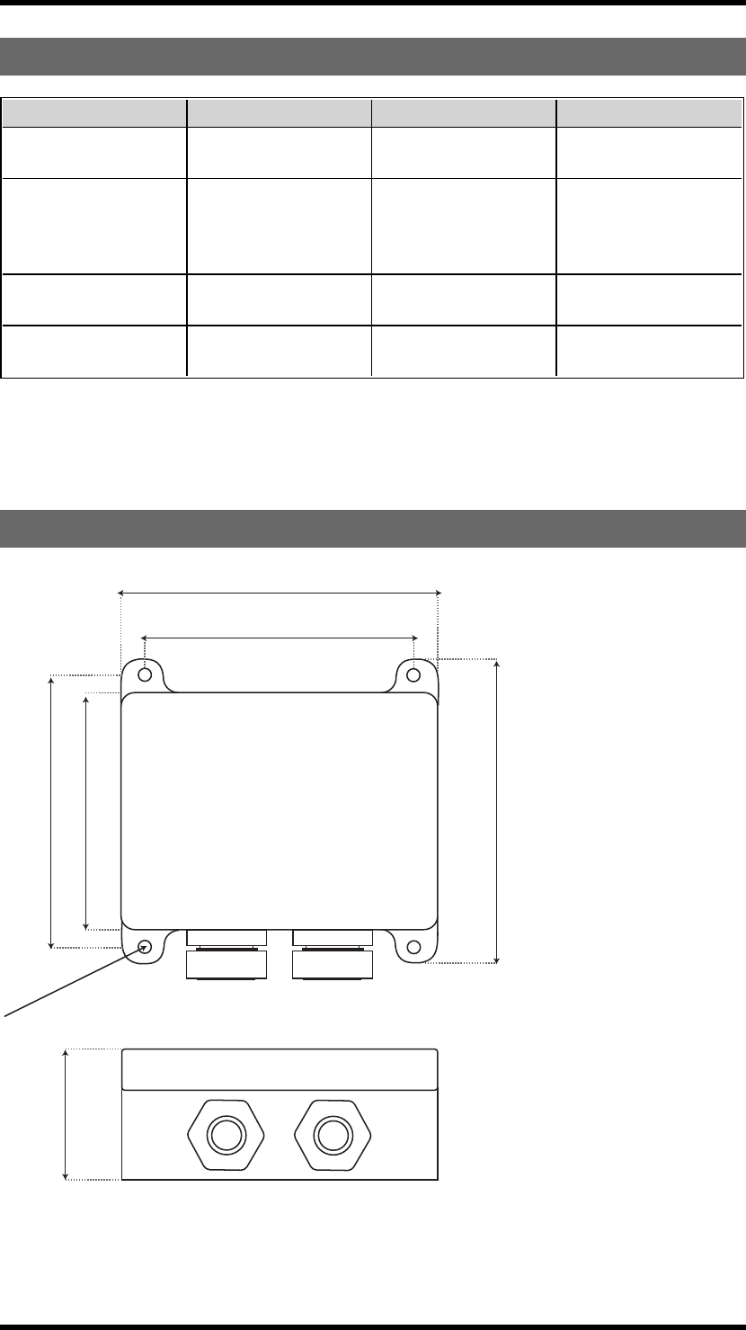
RECEIVER MEASUREMENTS
120.5 mm. (4.744 in.)
102 mm. (4.016 in.)
116.3 mm. (4.578 in.)
90.4 mm. (3.559 in.)
104 mm. (4.094 in.)
Ø
5 mm. (0.197 in.)
51 mm. (2.007 in.)
-12 -
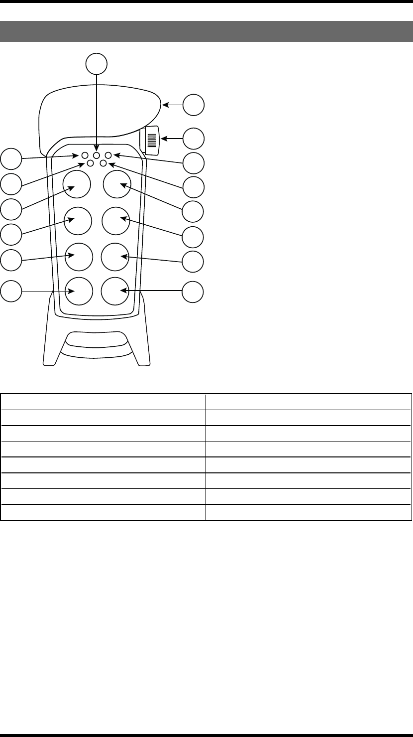
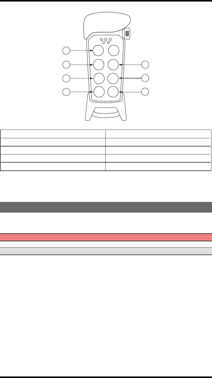
PN-TX-MX8B TRANSMITTER
1
2
3
4
11
6
5
7
13
12
14
8
9
10
15
1. Rubber cover 9. Button 3
2. Stop button 10. Button 5
3. LED 2 (red) 11. Button 7 - left start button
4. LED 4 (red) 12. Button 2
5. LED 1 (red) 13. Button 4
6. LED 3 (red) 14. Button 6
7. Top LED (red, green) 15. Button 8 - right start button
8. Button 1
-13 -
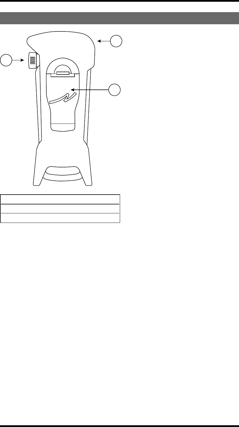
TRANSMITTER BACKSIDE
1
2
3
1. Rubber cover
2. Stop button
3. Battery pack
-14 -
TECHNICAL DATA
NO. OFBUTTONS
PN-TX-MX8B 8 x 2-step buttons
BATTERY
PN-TX-MX8B 3 x 1.5V AAA/LR03 in battery pack D4-3
ON/OFF SWITCH
PN-TX-MX8B No
DUPLEX COMMUNICATION
PN-TX-MX8B No
SIZE
PN-TX-MX8B 85 x 193 x 43 mm/3.4 x 7.7 x 1.7 in.
WEIGHT
PN-TX-MX8B 300 g./ 0.7 lbs.
OPERATING FREQUENCY
PN-TX-MX8B 2405-2480 MHz
NO. OF CHANNELS
PN-TX-MX8B 16 (channel 11-26)
CHANNEL SEPARATION
PN-TX-MX8B 5 MHz
OPERATING TIME (WITH CONTINUOUS USAGE)
PN-TX-MX8B Approx. 100 h. with alkaline (depending on
settings)
IP CLASS
PN-TX-MX8B 65
OPERATING TEMPERATURE
PN-TX-MX8B -20 - +55°C/ -4 - +130°F
NO. OF PIN CODES POSSIBLE
PN-TX-MX8B 1
-15 -
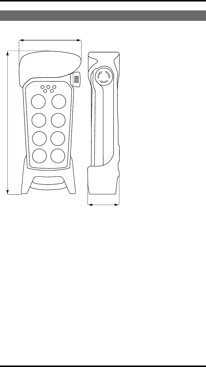
TRANSMITTER MEASUREMENTS
43 mm (1.7 in.)
193 mm (7.7 in.)
85 mm (3.4 in.)
-16 -

Chapter 4: INSTALLERS GUIDE
CHAPTER 4: INSTALLERS GUIDE
DEFAULT RADIO MODE
This transmitter is set to continuous radio mode by default. The transmitter starts to transmit
continuously as soon as it has been started up. The radio transmission ends when the stop button is
pressed. When the system is in continuous radio mode, button 7 + 8 are used as start buttons. When
the system is in discontinuous radio mode, no start buttons are used.
To establish a radio link between the transmitter and the receiver, both units need to be set to the same
radio mode. If you want to switch to discontinuous radio mode:
1. Set the receiver to an Operating mode that supports discontinuous radio mode.
2. Switch to discontinuous radio mode in the transmitter.
Note that some settings can only be made when the products are transmitting continuously. Those
sections are marked with the text: "Only for continuous radio mode".
When selecting Operating mode you have to know if the products are transmitting continuously or
discontinuously. Therefore you will find information on the Operating modes pages.
SWITCH RADIO MODE IN THE TRANSMITTER
NOTE! For discontinuous radio mode in the transmitter, the receiver must be set to an Operating mode
that supports discontinuous radio mode.
1. Make sure that the stop button is pressed.
2. Press button 8. Keep pressed.
3. Twist and pull out the stop button.
4. Release button 8.
Top LED flashes (green).
5. WITHIN 1 MINUTE FROM PULLING OUT THE STOP BUTTON:
Enter the code: 1-2-3-4 (press the buttons 1, 2, 3, 4).
The transmitter LEDs 1- 4 (red) light up. If the code is invalid, the transmitter turns off. If the code is
accepted, the top LED flashes (green), The transmitter LEDs 1-4 (red) starts to flash.
6. WITHIN 1 MINUTE FROM ENTERING THE CODE: Press button 1.
The top LED lights (green). LED 2 flashes (red).
7. Press a button to select radio mode:
Button 1 = continuous radio mode
Button 2 = discontinuous radio mode
8. The top LED flashes (green) 3 times. The transmitter turns off.
-17 -

Chapter 4: INSTALLERS GUIDE
START THE TRANSMITTER
NOTE! Only for continuous radio mode.
1. Make sure that the stop button is pressed.
2. Twist and pull out the stop button.
The top LED lights (green when the battery capacity is good, red when the battery capacity is poor),
LEDs 3 + 4 flash (red).
3. Press the start buttons (buttons 7 + 8) at the same time for at least 1 second.
LEDs 3 + 4 light (red).
4. Release the start buttons.
LEDs 3 + 4 go out.
The top LED flashes green.
START THE TRANSMITTER IN MENU MODE
1. Make sure that the stop button is pressed.
2. Press button 8. Keep pressed.
3. Twist and pull out the stop button.
4. Release button 8.
Top LED flashes (green).
5. WITHIN 1 MINUTE FROM PULLING OUT THE STOP BUTTON:
Enter the code: 1-2-3-4 (press the buttons 1, 2, 3, 4).
The transmitter LEDs 1- 4 (red) light up. If the code is invalid, the transmitter turns off. If the code is
accepted, the top LED flashes (green), The transmitter LEDs 1-4 (red) starts to flash.
6. WITHIN 1 MINUTE FROM ENTERING THE CODE: Enter a menu by pressing the buttons according
to the table below:
-18 -
Chapter 4: INSTALLERS GUIDE
1
3
5
6
4
2
7
1. Radio mode 6. Logout
2. Replace 7. Shift button
3. Show channel Shift+3. Switch channel
4. Auto shutdown Shift+5. Load at start-up
5. Load select mode
If no buttons are pressed within 1 minute, or if the stop button is pressed, the transmitter will turn off.
REGISTER THE TRANSMITTER IN THE RECEIVER
Register in continuous radio mode
WARNING! Keep only transmitters, that you intend to use, registered in the receiver.
NOTE! Only for continuous radio mode.
1. Make sure that the stop button is pressed.
2. Twist and pull out the stop button.
The top LED lights (green when the battery capacity is good, red when the battery capacity is poor),
LEDs 3 + 4 flash (red).
3. Press the start buttons (buttons 7 + 8) at the same time for at least 1 second.
LEDs 3 + 4 light (red).
4. Release the start buttons.
LEDs 3 + 4 go out.
The top LED flashes green.
5. Press the receiver Function button.
The function LED lights red.
6. Press the receiver Select button.
-19 -

Chapter 4: INSTALLERS GUIDE
All relay LEDs light red.
7. Press transmitter button 1 and 2. Keep pressed.
All relay LEDs light red.
8. The relay LEDs flash 2 times.
9. Release transmitter button 1 and 2.
The relay LEDs flash 1 time.
The transmitter is registered.
Register in discontinuous radio mode
WARNING! Keep only transmitters, that you intend to use, registered in the receiver.
NOTE! Only for discontinuous radio mode.
1. Press the receiver Function button.
The function LED lights red.
2. Press the receiver Select button.
All relay LEDs light red.
3. Press transmitter button 1 and 2. Keep pressed.
All relay LEDs light red.
4. The relay LEDs flash 2 times.
5. Release transmitter button 1 and 2.
The relay LEDs flash 1 time.
The transmitter is registered.
-20 -

ERASE ALL TRANSMITTERS FROM THE RECEIVER
1. Press the Function button in the receiver.
The red function LED lights.
2. Press the receiver Select button. Keep pressed.
All relay LEDs light red.
3. All relay LEDs go out.
4. Release the Select button.
All transmitters are erased from the receiver.
If the red function LED flashes, one or more transmitters are still registered in the receiver.
TURN THE TRANSMITTER OFF
1. Press the stop button.
NOTE! When the transmitter is active and the stop button is pressed, all relays go off.
REPLACE
You can replace a registered transmitter with another transmitter without having access to the receiver.
Use the new transmitter that you want to replace the old transmitter with.
1. Make sure that the stop button is pressed.
2. Press button 8. Keep pressed.
3. Twist and pull out the stop button.
4. Release button 8.
Top LED flashes (green).
5. WITHIN 1 MINUTE FROM PULLING OUT THE STOP BUTTON:
Enter the code: 1-2-3-4 (press the buttons 1, 2, 3, 4).
The transmitter LEDs 1- 4 (red) light up. If the code is invalid, the transmitter turns off. If the code is
accepted, the top LED flashes (green), The transmitter LEDs 1-4 (red) starts to flash.
6. WITHIN 1 MINUTE FROM ENTERING THE CODE:
Press button 3.
The top LED lights (green). LED 2 flashes (red).
7. Enter the replacement ID code (a maximum of 11 digits) for the transmitter that you want to replace
by pressing the transmitter buttons. IMPORTANT! When entering the last digit in the code, keep that
button pressed until you have pressed the stop button.
-21 -

IMPORTANT! The replacement ID code is placed
in the back of the transmitter. Remove the rubber
cover. This label is placed above the battery lid.
You will find the correct replacement ID code in
the bottom of the replacement code label.
8. Transmitter LED 3 lights (red) when one or more digits have been entered. Transmitter LEDs 3 + 4
(red) light when a maximum number of digits (11) have been entered.
9. Press the stop button. You can now release the button.
10. After approx. 10 seconds the transmitter turns off. NOTE! If replacing fails, press the stop button
and start over again.
-22 -

FREQUENCIES AND CHANNELS
Channel Frequency
11 2405 MHz
12 2410 MHz
13 2415 MHz
14 2420 MHz
15 2425 MHz
16 2430 MHz
17 2435 MHz
18 2440 MHz
19 2445 MHz
20 2450 MHz
21 2455 MHz
22 2460 MHz
23 2465 MHz
24 2470 MHz
25 2475 MHz
26 2480 MHz
Show channel
1. Make sure that the stop button is pressed.
2. Press button 8. Keep pressed.
3. Twist and pull out the stop button.
4. Release button 8.
Top LED flashes (green).
5. WITHIN 1 MINUTE FROM PULLING OUT THE STOP BUTTON:
Enter the code: 1-2-3-4 (press the buttons 1, 2, 3, 4).
The transmitter LEDs 1- 4 (red) light up. If the code is invalid, the transmitter turns off. If the code is
accepted, the top LED flashes (green), The transmitter LEDs 1-4 (red) starts to flash.
6. WITHIN 1 MINUTE FROM ENTERING THE CODE:
Press button 4.
The top LED lights (green).
7. The selected channel will be indicated in the following way:
LED1 (red) will flash the number of times corresponding to the first digit. LED 2 (red) will flash the
number of times corresponding to the second digit.
E.g. for channel 23: LED 1 (red) will flash 2 times, LED 2 (red) will flash 3 times.
-23 -

Switch channel
1. Make sure that the stop button is pressed.
2. Press button 8. Keep pressed.
3. Twist and pull out the stop button.
4. Release button 8.
Top LED flashes (green).
5. WITHIN 1 MINUTE FROM PULLING OUT THE STOP BUTTON:
Enter the code: 1-2-3-4 (press the buttons 1, 2, 3, 4).
The transmitter LEDs 1- 4 (red) light up. If the code is invalid, the transmitter turns off. If the code is
accepted, the top LED flashes (green), The transmitter LEDs 1-4 (red) starts to flash.
6. WITHIN 1 MINUTE FROM ENTERING THE CODE:
Press button 8. Keep pressed.
7. Press button 4. Release.
8. Release button 8.
The top LED lights (green). LED 2 (red) flashes.
9. Select channel 11-26.
For example: Press button 2 for the first digit in channel 20. To enter the zero, press button 8. Keep
pressed. Press button 4. Release button 4. Release button 8.
Press button... for digit...
1 1
2 2
3 3
4 4
5 5
6 6
8 (shift)+1 7
8 (shift)+2 8
8 (shift)+3 9
8 (shift)+4 0
LED 3 (red) lights when a valid digit has been entered.
LEDs 3 and 4 (red) light when two valid digits have been entered.
The top LED flashes (green) 3 times. The transmitter turns off.
-24 -
AUTOMATIC SHUTDOWN
NOTE! Only for continuous radio mode.
Turning on automatic shutdown can save battery capacity by automatically turning the transmitter off
when no function has been activated for a set time.
Set the time for automatic shutdown
1. Make sure that the stop button is pressed.
2. Press button 8. Keep pressed.
3. Twist and pull out the stop button.
4. Release button 8.
Top LED flashes (green).
5. WITHIN 1 MINUTE FROM PULLING OUT THE STOP BUTTON:
Enter the code: 1-2-3-4 (press the buttons 1, 2, 3, 4).
The transmitter LEDs 1- 4 (red) light up. If the code is invalid, the transmitter turns off. If the code is
accepted, the top LED flashes (green), The transmitter LEDs 1-4 (red) starts to flash.
6. WITHIN 1 MINUTE FROM ENTERING THE CODE:
Press button 5.
The top LED lights (green). LED 2 flashes (red).
7. Select the time that you want for automatic shutdown by pressing the buttons according to the table:
Press button... Automatic shutdown time after...
1 3 minutes
2 6 minutes
3 12 minutes
7 No automatic shutdown
The top LED flashes green 3 times. The transmitter turns off.
-25 -

LOGOUT
NOTE! Only for continuous radio mode.
NOTE! Quick logout can only be made when the transmitter is on and the radio link is up.
Quick logout
1. Press button 7. Keep pressed.
2. Press the stop button.
3. The transmitter is logging out for approx.10 seconds. The transmitter turns off.
Logout from receiver
1. Press the receiver Select button.
LED 10 (orange) lights.
2. Keep pressed (for more than 4 seconds).
LED 10 (orange) goes off.
3. The transmitter is now logged off. Any other registered transmitter can log in.
Logout from menu mode
1. Make sure that the stop button is pressed.
2. Press button 8. Keep pressed.
3. Twist and pull out the stop button.
4. Release button 8.
Top LED flashes (green).
5. WITHIN 1 MINUTE FROM PULLING OUT THE STOP BUTTON:
Enter the code: 1-2-3-4 (press the buttons 1, 2, 3, 4).
The transmitter LEDs 1- 4 (red) light up. If the code is invalid, the transmitter turns off. If the code is
accepted, the top LED flashes (green), The transmitter LEDs 1-4 (red) starts to flash.
6. WITHIN 1 MINUTE FROM ENTERING THE CODE:
Press button 7.
The top LED flashes (red).
7. The transmitter is logging out for approx.10 seconds. The transmitter turns off.
-26 -

RELAY FUNCTIONALITY
NOTE! If Operating mode 0 is selected, you can not make these settings. Contact your representative
for assistance.
NOTE! Momentary relay functionality is default. That means that the relay will only be activated when
you press a button on the transmitter. When the button is released, the relay deactivates. Setting a relay
to latching means that the relay gets activated every time that you press a button, but in this case the
relay remains active until the button is pressed again.
NOTE! Before starting to perform these settings, make sure that the stop relays are deactivated!
NOTE! The settings options depend on the selected Operating mode.
Momentary or latching relay functionality
1. Press the receiver Function button 2 times. LED 9 (yellow) lights. The relay LEDs light.
2. Press the receiver Select button to switch relay functionality. The relay LEDs flash to indicate that a
latching or momentary functionality can be set to the corresponding relays.
3. Press the receiver Function button to set latching or momentary functionality:
LED 9 (yellow) off= momentary relay functionality
LED 9 (yellow) on = latching relay functionality
4. Press the receiver Select button to step to the next available relay. When you have stepped through
all the available relays, the receiver exits the settings menu.
-27 -
Chapter 5: OPERATING MODES
CHAPTER 5: OPERATING MODES
SELECT OPERATING MODE
NOTE! Go to the Operating modes pages to see what Operating modes that are available when
transmitting in continuous/ discontinuous radio mode. Operating modes do not work for both radio
modes.
1. Press the receiver Function button 4 times.
LED 11 (orange) lights.
2. Press the receiver Select button to see what Operating mode that is used.
The relay LEDs light according to the table below, LED 11 flashes in orange.
When relay LED no. light(s)... the selected Operating mode is...
0 0*
1 1
2 2
1+2 3
3 4
1+3 5
ALL 255*
3. Press the receiver Function button to step one Operating mode number at the time.
Example: You know that Operating mode 2 is selected, because relay LED 2 lights. When pressing the
Function button one time, you would go to Operating mode 3 and LEDs 1+2 light. If you want to go to
Operating mode 4, you would press the Function button one more time and LED 3 lights.
4. Press the receiver Select button to select Operating mode. The receiver exits the Operating mode
menu and restarts.
*Operating modes that are reserved for specific customer applications can only be set in the PC
program Settings manager. Contact your representative for assistance.
-28 -
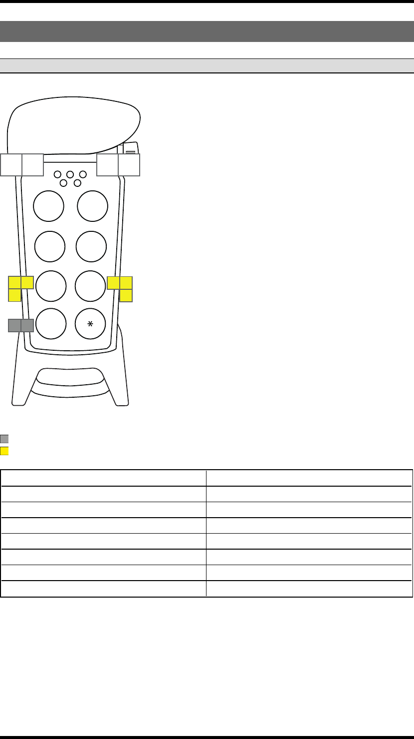
OPERATING MODE 1
NOTE! Only for continuous radio mode.
1 1 2 2
6 6 7 7
9 9 10 10
3 3
8 8
11 11
4 4
2nd
step 1st
step 2nd
step
1st
step
* Depending on transmitter Load select mode
Button functions
Direction functions
On relays Relay 5 is active when radio link is up
Work relays -
Recommended Load select mode 0, 1,3
Load select relays -
Programmable settings Relay 4 can be set to latching
Interlocking Between button pairs: 1-2, 3-4, 5-6
Radio mode Continuous
Zero position check Active on all functions
-29 -
OPERATING MODE 2
NOTE! Only for continuous radio mode.
112 2
33
4 4
2nd
step 1st
step 2nd
step
1st
step
* Depending on transmitter Load select mode
Button functions
Direction functions
On relays Relay 5 is active when radio link is up
Work relays -
Recommended Load select mode 0, 1, 3
Load select relays -
Programmable settings Relay 4 can be set to latching
Interlocking Between button pairs: 5-6
Radio mode Continuous
Zero position check Active on all functions
-30 -

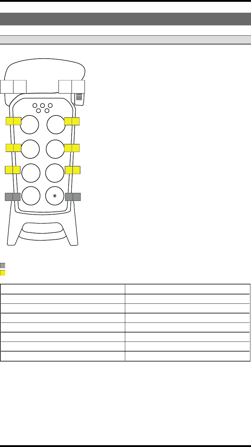
OPERATING MODE 3
NOTE! Only for continuous radio mode.
1 1 2 2
6 6 7 7
34
8 9
11 11
2nd
step 1st
step 2nd
step
1st
step
10 10
* Depending on transmitter Load select mode
Button functions
Direction functions
On relays Relay 5 is active when radio link is up
Work relays -
Recommended Load select mode 0, 1, 3
Load select relays -
Programmable settings Relays 10-11 can be set to latching
Interlocking Between button pairs: 1- 2, 3- 4
Radio mode Continuous
Zero position check Active on all functions
-31 -
OPERATING MODE 4
NOTE! Only for continuous radio mode.
1 1 2 2
3 3 4 4
6 6 7 7
10 10 1111
2nd
step 1st
step 2nd
step
1st
step
* Depending on transmitter Load select mode
Button functions
Direction functions
On relays Relay 5 is active when radio link is up
Work relays -
Recommended Load select mode 0, 1, 3
Load select relays -
Programmable settings Relays 10-11 can be set to latching
Interlocking Between button pairs: 1- 2, 3- 4, 5-6
Radio mode Continuous
Zero position check Active on all functions
-32 -
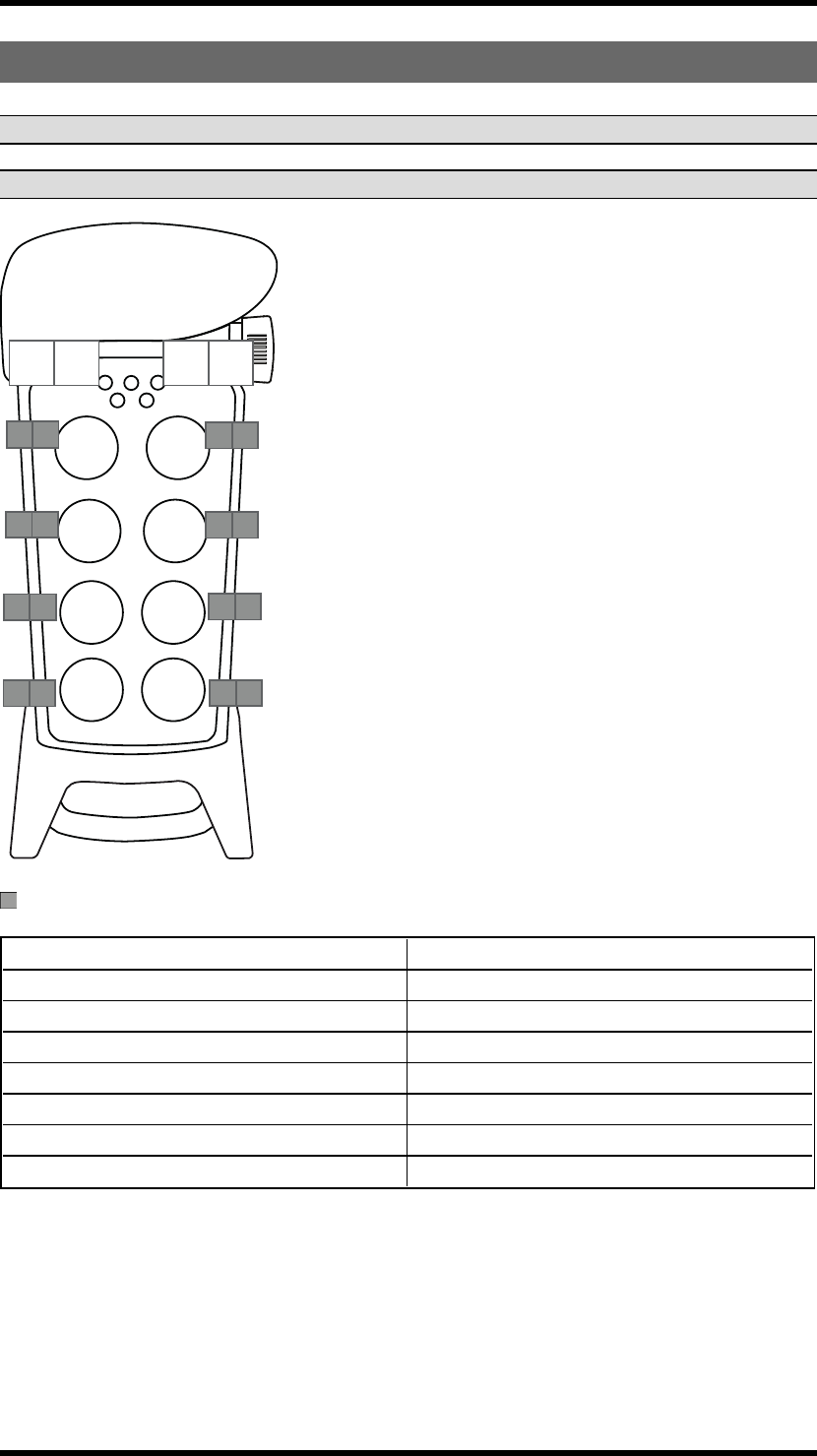
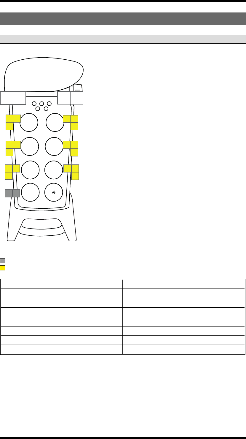
OPERATING MODE 5
NOTE! Only for discontinuous radio mode.
NOTE! Discontinuous radio mode cancels the PL d safety classified stop function.
2nd
step 1st
step 2nd
step
1st
step
8 8 9 9
1 1 2 2
3 3 4 4
6 6 7 7
Button functions
On relays -
Work relays Relay 5 is active when relay 1-4 or 6-11 is active
Recommended Load select mode 0
Load select relays -
Programmable settings Relay 1-4, 6-11 can be set to latching
Interlocking -
Radio mode Discontinuous
Zero position check -
-33 -
Chapter 6: LOAD SELECT MODES
CHAPTER 6: LOAD SELECT MODES
MAKE A LOAD SELECTION
NOTE! Only for continuous radio mode.
NOTE! Load select mode 0 is default.
1. Make sure that the stop button is pressed.
2. Press button 8. Keep pressed.
3. Twist and pull out the stop button.
4. Release button 8.
Top LED flashes (green).
5. WITHIN 1 MINUTE FROM PULLING OUT THE STOP BUTTON:
Enter the code: 1234 (press the buttons 1, 2, 3, 4).
The transmitter LEDs 1- 4 (red) light up. If the code is invalid, the transmitter turns off. If the code is
accepted, the top LED flashes (green), The transmitter LEDs 1-4 (red) starts to flash.
6. WITHIN 1 MINUTE FROM ENTERING THE CODE:
Press button 6.
The top LED lights (green). LED 2 flashes (red).
7. To select a Load select mode, press a button according to the table:
Press button... for Load select mode... with this load selected at start-up
7 0 none
11A
22A
33A
44A
The top LED flashes (green) 3 times. The transmitter turns off.
-34 -
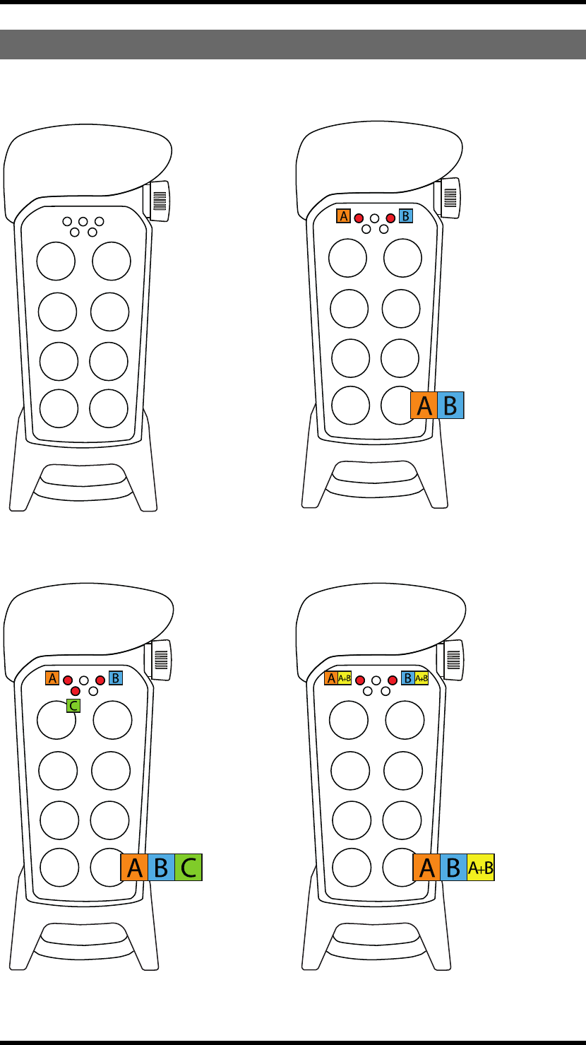
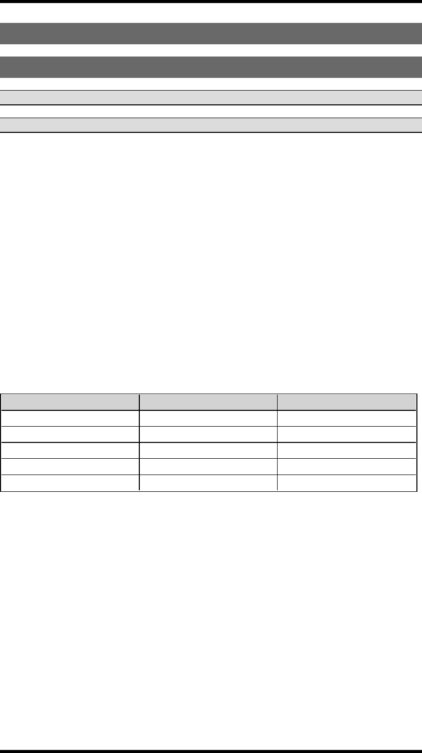
LOAD SELECT MODE 0-4
Load select mode 0 Load select mode 1
Load select mode 2 Load select mode 3
-35 -
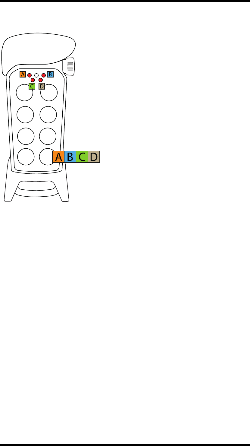
Load select mode 4
-36 -
LOAD AT START-UP
NOTE! We recommend starting with Load select before selecting load at start-up.
1. Make sure that the stop button is pressed.
2. Press button 8. Keep pressed.
3. Twist and pull out the stop button.
4. Release button 8.
Top LED flashes (green).
5. WITHIN 1 MINUTE FROM PULLING OUT THE STOP BUTTON:
Enter the code: 1-2-3-4 (press the buttons 1, 2, 3, 4).
The transmitter LEDs 1- 4 (red) light up. If the code is invalid, the transmitter turns off. If the code is
accepted, the top LED flashes (green), The transmitter LEDs 1-4 (red) starts to flash.
6. WITHIN 1 MINUTE FROM ENTERING THE CODE:
Press button 8. Keep pressed.
7. Press button 6. Release.
8. Release button 8.
The top LED lights (green). LED 2 (red) flashes.
9. To select Load at start-up, press a button according to the table below:
Press... for Load at start-up...
Button 7 none
Button 1 A
Button 2 B
Button 3 A+B
-37 -
Chapter 7: BATTERY GUIDE
CHAPTER 7: BATTERY GUIDE
BATTERY INFORMATION
NOTE! Electronics and batteries must be physically separated before disposal. Make sure that
electronics or batteries are not thrown in the household waste.
NOTE! Two different battery solutions - D4-2 and D4-3 - are available for use in the transmitter.
BATTERY TYPE
D4-2 Replaceable, rechargeable lithium-ion battery
D4-3 Replaceable battery pack with 3 x 1.5V
AAA/LR03 batteries
OPERATING TIME
D4-2 Approx. 150 h.(depending on settings)
D4-3 Approx. 100 h. with alkaline (depending on
settings)
CHARGE
D4-2 Charge in the Tele Radio AB charger unit
D4-3 Do not charge in the Tele Radio AB charger unit.
Switch the batteries inside the battery pack.
CHARGING TEMPERATURE
D4-2 0-45°C/32-113°F
D4-3 Not applicable
-38 -

SWITCH BATTERIES
Switch batteries in the battery pack D4-3
WARNING! Do not charge the battery pack D4-3 in the Tele Radio AB charger unit or in any other
way.
NOTE! Electronics and batteries must be physically separated before disposal. Make sure that
electronics or batteries are not thrown in the household waste.
1. Remove the battery pack from the back of the transmitter.
2. Open up the battery pack.
3. Switch the 3 x 1.5V AAA/LR03 batteries. Use alkaline batteries for optimal performance.
4. Put the battery pack back in the transmitter.
BATTERY PRECAUTIONS
Observe the following general battery warnings:
nAs batteries contains flammable substances such as lithium or other organic solvents, they may
cause heating, rupture or ignition.
nRisk of explosion if battery is replaced with a battery of an incorrect type.
nDo not short circuit, disassemble, deform or heat batteries.
nNever try to charge a visibly damaged or frozen battery.
nKeep batteries out of reach of small children. Should a child swallow a battery, consult a phys-
ician immediately.
nAvoid direct soldering to batteries.
nWhen discarding batteries, insulate the + and - terminals of batteries with insulating/ masking
tape. Do not put multiple batteries in the same plastic bag.
nWhen improperly disposed, batteries may short circuit, causing them to become hot, burst or
ignite.
nStore in a cool location. Keep batteries away from direct sunlight, high temperature, and high
humidity.
nDo not throw batteries into fire.
-39 -

ROHS AND WEEE
In accordance with Directive 2011/65/EU on restriction of the use of certain hazardous substances in
electrical and electronic equipment (RoHS) and Directive 2012/19/EU on waste electrical and
electronic equipment (WEEE), Tele Radio AB strives to minimize the use of hazardous materials,
promotes reuse and recycling, and reduces emissions to air, soil and water. When a commercially viable
alternative is available, Tele Radio AB strives to restrict or eliminate substances and materials that pose
an environmental, health or safety risk.
GUARANTEE, SERVICE, REPAIRS AND MAINTENANCE
The Tele Radio AB products are covered by a guarantee/warranty against material, construction and
manufacturing faults. During the guarantee/warranty period, Tele Radio AB may replace the product or
faulty parts. Work under guarantee/warranty must be carried out by Tele Radio AB or by an authorized
service centre specified by Tele Radio AB.
This is not covered by the guarantee/ warranty:
nFaults resulting from normal wear and tear
nParts of a consumable nature
nProducts that have been subject to unauthorized modifications
nFaults resulting from incorrect installation and use
nDamp and water damage
Maintenance:
nRepairs and maintenance must be carried out by qualified personnel
nUse spare parts from Tele Radio AB only
nContact your representative if you require service or other assistance
nKeep the product in a dry, clean place
nKeep contacts and antennas clean
nWipe off dust using a slightly damp, clean cloth
WARNING! Never use cleaning solutions or high-pressure water.
-40 -

Chapter 8: CERTIFICATIONS CHAPTER
CHAPTER 8: CERTIFICATIONS CHAPTER
FCC STATEMENT
Statement for warning:
To satisfy FCC RF exposure requirements, a separation distance of 20 cm or more should be maintained
between the antenna of this device and persons during device operation.
To ensure compliance, operations at closer than this distance is not recommended.
Les antennes installées doivent être situées de facon à ce que la population ne puisse y être exposée à
une distance de moin de 20 cm. Installer les antennes de facon à ce que le personnel ne puisse
approcher à 20 cm ou moins de la position centrale de l' antenne.
La FCC des éltats-unis stipule que cet appareil doit être en tout temps éloigné d'au moins 20 cm des
personnes pendant son functionnement.
Caution: The user is cautioned that changes or modifications not expressly approved by the party
responsible for compliance could void the user's authority to operate the equipment.
This device complies with Industry Canada licence-exempt RSS standard(s) and Part 15 of the FCC
Rules. Operation is subject to the following two conditions:
(1) this device may not cause harmful interference, and
(2) this device must accept any interference received, including interference that may cause undesired
operation.
Le présent appareil est conforme aux CNR d'Industrie Canada applicables aux appareils radio exempts
de licence et la partie 15 des Règles FCC. L'exploitation est autorisée aux deux conditions suivantes :
(1) l'appareil ne doit pas produire de brouillage, et
(2) l'utilisateur de l'appareil doit accepter tout brouillage radioélectrique subi, même si le brouillage est
susceptible d'en compromettre le fonctionnement.
This equipment complies with FCC and IC radiation exposure limits set forth for an uncontrolled
environment. End user must follow the specific operating instructions for satisfying RF exposure
compliance. This transmitter must not be co-located or operating in conjunction with any other antenna
or transmitter.
Cet appareil est conforme aux limites d’exposition au rayonnement RF stipulées par la FCC et l’IC pour
une utilisation dans un environnement non contrôlé. L'utilisateur final doit suivre les instructions de
fonctionnement spécifiques pour le respect d'exposition aux RF. Lesémetteurs ne doivent pas être
placées près d’autres antennes ou émetteurs ou fonctionner avec ceux-ci.
Note: this equipment has been tested and found to comply with the limits for a class b digital device,
pursuant to part 15 of the FCC rules. These limits are designed to provide reasonable protection against
harmful interference in a residential installation. This equipment generates, uses and can radiate radio
frequency energy and, if not installed and used in accordance with the instructions, may cause harmful
interference to radio communications. However, there is no guarantee that interference will not occur
in a particular installation. If this equipment does cause harmful interference to radio or television
reception, which can be determined by turning the equipment off and on, the user is encouraged to try
to correct the interference by one or more of the following measures:
—reorient or relocate the receiving antenna.
—increase the separation between the equipment and receiver.
—connect the equipment into an outlet on a circuit different from that to which the receiver is
connected.
—consult the dealer or an experienced radio/TV technician for help.
Under Industry Canada regulations, this radio transmitter may only operate using an antenna of a type
and maximum (or lesser) gain approved for the transmitter by Industry Canada. To reduce potential
radio interference to other users, th antenna type and its gain should be so chosen that the equivalent
isotropically radiated power (e.i.r.p.) is not more than that necessary for successful communication.
-41 -
Chapter 8: CERTIFICATIONS CHAPTER
Conformément à la réglementation d'Industrie Canada, le présent émetteur radio peut fonctionner avec
une antenne d'un type et d'un gain maximal (ou inférieur) approuvé pour l'émetteur par Industrie
Canada. Dans le but de réduire les risques de brouillage radioélectrique à l'intention des autres
utilisateurs, il faut choisir le type d'antenne et son gain de sorte que la puissance isotrope rayonnée
équivalente (p.i.r.e.) ne dépasse pas l'intensité nécessaire à l'établissement d'une communication
satisfaisante.
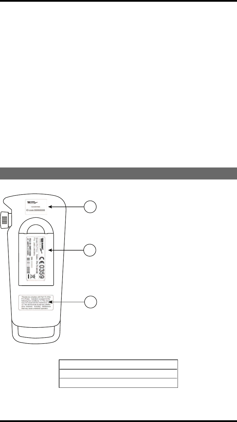
PRODUCT AND FCC/IC LABELS ON THE TRANSMITTER
3
2
1
1. Label with replacement ID code
2. Product label
3. FCC statement label
-42 -
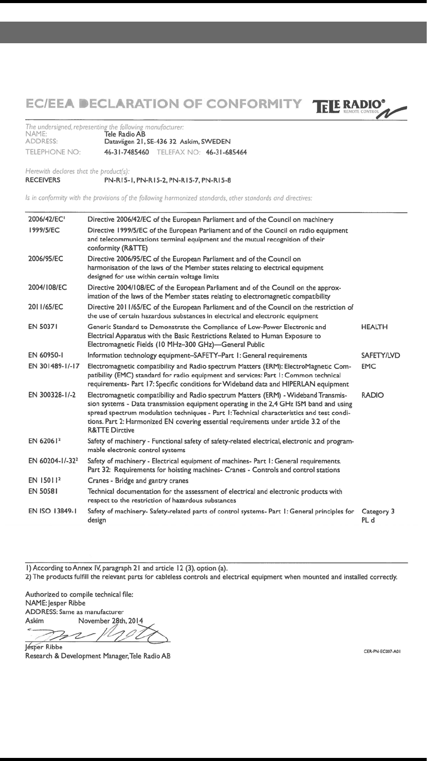
EC/EEA DECLARATION OF CONFORMITY
-43 -