Tele Radio T4LION433 TRANSMITTER User Manual FCC IC 860JD 091215

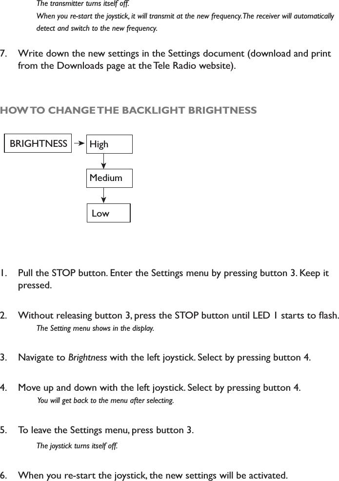
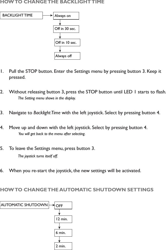
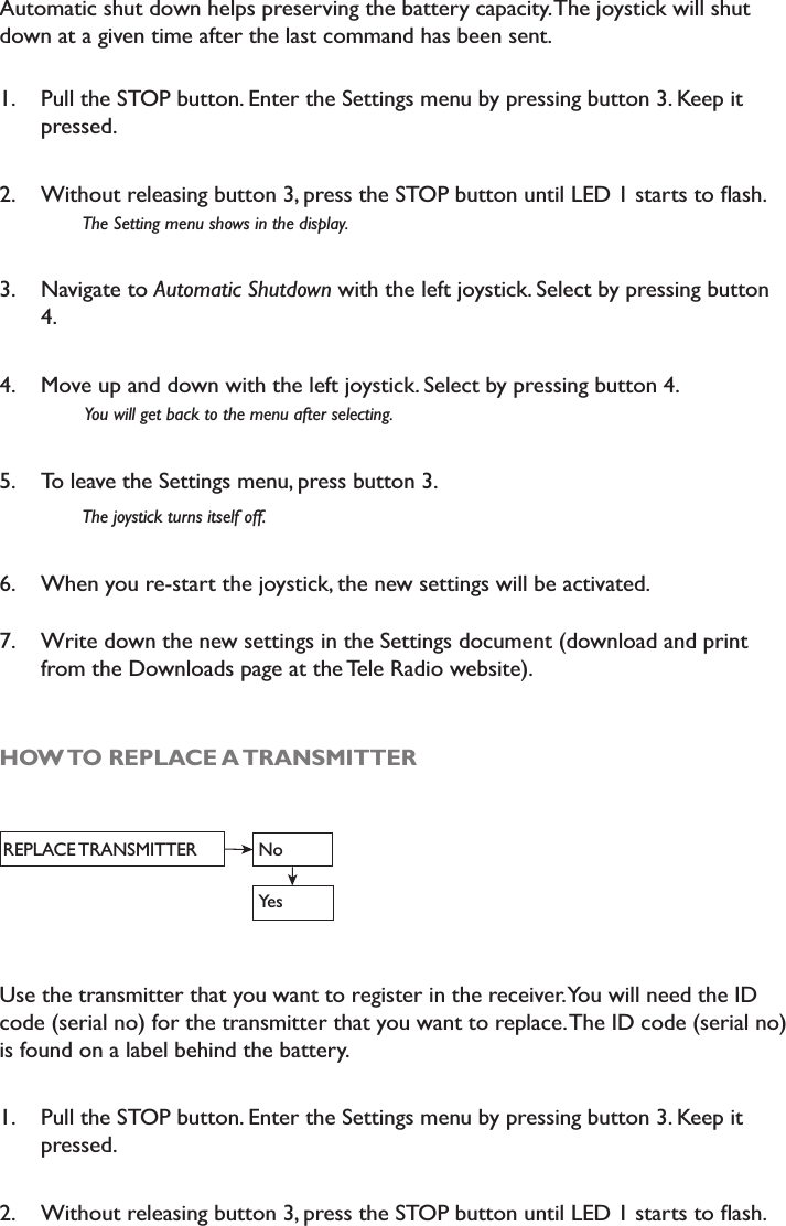
Tele Radio AB TRANSMITTER FCC IC 860JD 091215

ONFT4LION433 & 4807A-T4LION433 user manual rev1

Tele Radio 860 LIONIM-860-014-A4JOYSTICK TRANSMITTER TX4-A, TX4-BINSTALLATION MANUALMODEL NO: TX4-A= T00004-38, T00004-40. TX4-B= T00004-39 T00004-41
CONTENTSReceiver overview               3Joystick overview               4Frequency table                 6Receiver                 8Place the receiver and the antenna            9Joystick                  10How to start up in operating mode           11How to turn off                 11How to register the joystick in the receiver          11How to erase all joysticks from the receiver         12How to log in/ log out the joystick            13Settings menu                 13Settings menu map               13How to navigate in the settings menu           13How to start up in menu mode             14How to switch channel               14How to change backlight brightness           15How to change backlight time             16How to replace the transmitter             17Settings document               18Radio transmission               19Battery                  21Placement of IC and FCC labels            23Guarantee                 24
RECEIVER____________________________________________*42 43 44 45  46  47  48  49  50  51  52  53  54  55  56  57  58  59  60  61  62  63  64  65  66  67  68  69  70  71  72  73  74  75  76  77  78  79  80  81  82  83  1  2  3  4  5  6  7  8  9  10  11  12  13  14  15  16  17  18  19  20  21  22  23  24  25  26  27  28  29  30  31  32  33  34  35  36  37  38  39  40  41 230 VAC115 VAC48 VAC0 VAC24 VAC12 VAC0 VACSR1 SR2SR1SR2S1* S3* S2860RX1=   Red LED 12=    Yellow LED 23=   Reset button4=   Green LED 45=   Red LED 56=    Yellow LED 67=   Function selector switch8=   Green LED 89=   Red LED 910=   Yellow LED 1011= Radio Module12= Green LED 12* Fuse S1, S2 and S3 ceramic slow.S1 200 mAS2 300-315 mAS3 500 mA234567189101112
JOYSTICK____________________________________________DISPLAY1 4 258673FRONT SIDE1. Left joystick   3. Front switch         5. STOP button   7. Red/ green LED 22. Right joystick   4. Function switch       6. Red/ green LED 1 8. Display
LEFT SIDE    RIGHT SIDE4351 23. Button 34. Button 45. STOP button1. Side button 12. Side button 2FUNCTIONALITY OF THE 2 JOYSTICK SWITCHES__________________________________________FRONT SWITCH2 steps (OFF/ON) Toggling/latching relay function (i. e. spring loaded 2 step switch)Starts up in OFF modeFUNCTION SWITCH3 steps switchSelects functionality 1, 1+2, 2 OR 1,(NO FUNCTION), 2.The switch function is toggling/ latching (i. e. the functionality remains until the switch is being moved again).The position of the function switch shows what receiver, which group of relays or what lift on an overhead crane that is currently under control (not in joystick function selector mode 0).11+2/02
FREQUENCY TABLE (69 CHANNELS)____________________________________________CHANNEL FREQUENCY CHANNEL FREQUENCY01 433,075 MHz 36 433,950 MHz02 433,100 MHz 37 433,975 MHz03 433,125 MHz 38 434,000 MHz04 433,150 MHz 39 434,025 MHz05 433,175 MHz 40 434,050 MHz06 433,200 MHz 41 434,075 MHz07 433,225 MHz 42 434,100 MHz08 433,250 MHz 43 434,125 MHz09 433,275 MHz 44 434,150 MHz10 433,300 MHz 45 434,175 MHz11 433,325 MHz 46 434,200 MHz12 433,350 MHz 47 434,225 MHz13 433,375 MHz 48 434,250 MHz14 433,400 MHz 49 434,275 MHz15 433,425 MHz 50 434,300 MHz16 433,450 MHz 51 434,325 MHz17 433,475 MHz 52 434,350 MHz18 433,500 MHz 53 434,375 MHz19 433,525 MHz 54 434,400 MHz20 433,550 MHz 55 434,425 MHz21 433,575 MHz 56 434,450 MHz22 433,600 MHz 57 434,475 MHz23 433,625 MHz 58 434,500 MHz24 433,650 MHz 59 434,525 MHz25 433,675 MHz 60 434,550 MHz26 433,700 MHz 61 434,575 MHz27 433,725 MHz 62 434,600 MHz28 433,750 MHz 63 434,625 MHz29 433,775 MHz 64 434,650 MHz30 433,800 MHz 65 434,675 MHz31 433,825 MHz 66 434,700 MHz32 433,850 MHz 67 434,725 MHz33 433,875 MHz 68 434,750 MHz34 433,900 MHz 69 434,775 MHz35 433,925 MHz
IMPORTANT INFORMATION____________________________________________READ THIS INFORMATION AND THE  INSTRUCTIONS CAREFULLY BEFORE ASSEMBLING, INSTALLING AND PROGRAMMING TELE RADIO PRODUCTS. Tele Radio cannot be held responsible for any damage or other fault caused by a failure to follow the instructions. Failure to do so may invalidate the warranty. These instructions contain information on the installation and configuration of the remote radio control unit on the machine and are not intended to be passed on to the end-user. The machine manufacturer is obliged to produce an operating guide for the machine, which also describes the safe and appropriate operation by remote radio control. Only such information that the end-user needs to operate the machine by remote control should be passed on.IT IS YOUR RESPONSIBILITY TO FIND OUT ABOUT THE LAWS AND REGULATIONS THAT APPLY IN YOUR COUNTRY / STATE / CITY AND COUNTY!SAFETY INSTRUCTIONS This product should only be installed by licensed or qualified personnel. Switch the power supply to the receiver off before connecting the equipment. Turn off the transmitter when not in use. Keep a clear view of the work area. Make sure to use undamaged cables. Make sure that cables do not hang loose. Avoid installing the product in areas affected by strong vibrations. Allow only qualified and trained personnel to operate or have access to transmitter. Do not leave the transmitter unsupervised. Contact your dealer for repair and maintenance work on the product. Retain instructions for future reference and re-programming of the system.Visit our website for FAQ & the latest information:www.tele-radio.com
THE RECEIVER 860RX___________________________________________TECHNICAL DATA RELAY OUTPUTS:    MIDI: 10 + 2 for STOP function      MAXI: 24 + 2 for STOP functionSTOP RELAYS:    Potential free*, makes/ breaks 16A ACIFUNCTION RELAY:    Potential free*, makes/ breaks 16A ACIOPERATING FREQUENCY: 433.075-434.775 MHz.CHANNELS:    69SIZE:      256 x 217 x 85 mm. WEIGHT:      1900 - 2100 g.DEGREE OF PROTECTION: IP65*potential-free means that you need to supply voltage to get power out of a relay (e.g. via a connection comb).IMPORTANT!  To utilize the safety, relays SR1 and SR2 shall be used as stop relays in the safety circuitry of the object to be controlled. SUPPLY VOLTAGE MIN. POWER CONSUMPTION: MAX. POWER CONSUMPTION: 12V DC 150 mA. 1 A.24V DC 60   mA. 600 mA.24V AC 80   mA. 800 mA.48V AC 100 mA. 400 mA.115V AC 70   mA. 200 mA.230V AC 25   mA. 100 mA.123SR1SR24 567 8 9 108   9  10  11  12 13  14 15  16 17  18  19 20  21  22 23  24  25 26 27  28  29 30  31 32  33 34  35  36 37  38 39  40  411   2   3   4 5   6   7230VAC115VAC48 VAC0 V24V AC/DC12V DC0 VC NO NC C NO NCC NO NC CNO NC C NO NC C NO NC C NO NCSR21234 5 6SR1C NO NC C NO NC C NO NC78 9 10
PLACE THE RECEIVER Well away from wind, damp and water. Cable holders and vent plugs must face down to prevent water from seeping in.  If the receiver is to be placed in a a hard-to-reach place, it is advisable to complete the settings in the receiver before mounting it. Place receiver as high as possible off the ground. Place receiver in as free position as possible. Well away from metal objects, such as metal girders, high-voltage cables and other antennas.PLACE THE ANTENNA Check that there is a good connection between the antenna and the material on which it has been installed, e.g. after repainting of the chassis. Check that the antenna aerial and any coaxial cables are undamaged. Check that the antenna is directed upwards. The 1/2-wave antenna is ground plane independent. If the receiver is installed on a wall, the antenna should be angled out from the wall The 1/4-433K antenna with a 3 metres coaxial cable for high and XQREVWUXFWHGSODFHPHQW)RURSWLPXPUDQJHLQVWDOORQDÁDWURRIIUHHfrom other metal objects and antennas. When installing the antenna on a vehicle, use a vehicle bracket (F1). The 5/8-wave antenna with a 3 metres coaxial cable for high and XQREVWUXFWHGSODFHPHQW)RURSWLPXPUDQJHLQVWDOORQDÁDWURRIIUHHfrom other metal objects and antennas. When installing the antenna on a wall, use a wall bracket (VM1).1/21/4-433K5/8
JOYSTICK TRANSMITTER____________________________________________TECHNICAL DATA860TX4-AJOYSTICK FUNCTIONS:    Left 4x4, right 0x4DEGREE OF PROTECTION:  IP 65 OPERATING FREQUENCY:  433.075-434.775 MHz CHANNELS:       69SIZE:         145 mm. x 210 mm. x 130 mm.WEIGHT:       1200 g.BATTERY:       1 external, rechargeable battery (li-ion)860TX4-BJOYSTICK FUNCTIONS:    Left 2x2, right 0x2DEGREE OF PROTECTION:  IP 65 OPERATING FREQUENCY:  433.075-434.775 MHz CHANNELS:       69SIZE:         145 mm. x 210 mm. x 130 mm.WEIGHT:       1200 g.BATTERY:       1 external, rechargeable battery (li-ion)
HOW TO START UP IN OPERATING MODE1. Pull out the STOP button.The green/red LEDs 1+2 light up. Green when battery capacity is good, red when the battery needs to be charged. See how to charge the battery in “Battery- how to charge”.2. Press the side buttons 3+4  for about 0.30 seconds until LEDs 1+2 go out.  The buzzer sounds. HOW TO TURN OFF1. Press the STOP button. The joystick is now turned off.         LED 1+ LED 2 light red for approx. 3 seconds. NOTE! All relays disconnect when the STOP button is pressed.HOW TO REGISTER THE JOYSTICK IN THE RECEIVER The receiver can store up to 3 different transmitters. Each transmitter has a unique code. Receiver-LEDs 6 and 10 indicate the number of transmitters that are registered in the receiver.1RWÁDVKLQJ  No transmitter/ joystick is registeredÁDVK  1 transmitter/joystick is registeredÁDVKHV  2 transmitter/joysticks are registeredÁDVKHV  3 transmitter/joysticks are registered1. Turn the receiver Function selector switch 2 to ON position.2. Press the receiver Reset button.        Receiver LEDs 4,5, 6, 8, 9 and10 light up.3. Release the receiver Reset button.        Receiver LEDs 4, 8, 5 and 9 go out. Yellow receiver LEDs 6 and 10 light up when the receiver is ready to         register.127(,IWKH\HOORZDQGUHGUHFHLYHU/('VÁDVKDOWHUQDWLQJWKHPD[LPXPQXPEHURIWUDQVPLWWHUVMR\VWLFNV        have already been registered in the receiver.
4. Start up the joystick in operating mode. 5. Press the joystick side buttons 2+4 at the same time. Keep pressed until the \HOORZUHFHLYHU/('VDQGVWDUWWRÁDVK6. Turn the receiver Function selector switch 2 to OFF position.7KHMR\VWLFNLVQRZUHJLVWHUHGLQWKHUHFHLYHU7. Write down the new settings in the Settings document (download and print from the Tele Radio website)IMPORTANT! For safety reasons, avoid storing transmitters in receivers, where you don´t intend to use it. HOW TO ERASE ALL JOYSTICKS FROM THE RECEIVER127(<RXKDYHWRHUDVHDOOUHJLVWHUHGWUDQVPLWWHUVZKHQHUDVLQJRQH1. Turn the receiver Function selector switch 2 to ON position.2. Press the receiver Reset button.         The receiver LEDs 4, 5, 6, 8, 9 and 10 light continuously.3. Release the receiver Reset button.         All LEDs go out, except for the receiver LEDs 6, and 10.4. Turn the receiver Function selector switch 2 to OFF position. PERFORM THE NEXT STEP WITHIN 2 SECONDS: 5. Turn the receiver Function selector switch 2 to ON position.7KHUHFHLYHU/('VDQGÁDVK6. Turn the receiver Function selector switch 2 to OFF position. $OOUHJLVWHUHGWUDQVPLWWHUVDUHQRZHUDVHGIURPWKHUHFHLYHU
HOW TO LOG IN/ LOGOUT THE JOYSTICKWhen you start up a registered transmitter, it logs in to the receiver. The receiver will only accept this transmitter (even though other transmitters may be registered in the receiver) until it´s being logged out. If you want to use another transmitter, you have to log out the transmitter from the receiver. 1. The joystick, that is logged in, must be in operating mode.2. Press button 4.3. Without releasing button 4, press the STOP button.4. The display shows the text “Log out” and the transmitter turns itself off. The transmitter is now logged out. When you start a registered transmitter, it will now automatically log in to the receiver. SETTINGS MENUSETTINGS MENU MAPCHANNELBRIGHTNESSSETTINGS MENUBACKLIGHT TIMEAUTO SHUTDOWNREPLACE TRANSMITTERHOW TO NAVIGATE IN THE SETTINGS MENU TO MOVE UP AND DOWN: Use the left joystick. TO SELECT: Use button 4.  TO GO BACK: Use the left joystick.  TO EXIT: Press button 3 or pull out the STOP button. The transmitter will turn off.
HOW TO START UP IN MENU MODE1. Pull out the STOP button.The  LEDs 1+2 light green when battery capacity is good, red when battery needs to be    charged. See how to charge the battery in the section Battery- how to charge.2. Press button 3 and keep pressed.3. Press the STOP button while still pressing button 3. /('VWDUWVÁDVKLQJ4. Release button 3.  /('JRHVRXWDQGWKH6HWWLQJVPHQXVKRZVLQWKHGLVSOD\HOW TO SWITCH CHANNELChannel 69...CHANNEL...channel 1Go to the frequency table in the beginning of the installation instruction. The joysticks are pre-programmed to transmit at various frequencies. 1. Pull the STOP button. Enter the Settings menu by pressing button 3. Keep it pressed. 2. :LWKRXWUHOHDVLQJEXWWRQSUHVVWKH6723EXWWRQXQWLO/('VWDUWVWRÁDVK7KH6HWWLQJPHQXVKRZVLQWKHGLVSOD\3. Select Channel in the Settings menu by pressing button 4. 4. Move up and down with the left joystick. Keep pressed to move several steps. 5. Select by pressing button 4. <RXZLOOJHWEDFNWRWKHPHQXDIWHUVHOHFWLQJ6. To leave the Settings menu, press button 3.
 7KHWUDQVPLWWHUWXUQVLWVHOIRII :KHQ\RXUHVWDUWWKHMR\VWLFNLWZLOOWUDQVPLWDWWKHQHZIUHTXHQF\7KHUHFHLYHUZLOODXWRPDWLFDOO\ GHWHFWDQGVZLWFKWRWKHQHZIUHTXHQF\7. Write down the new settings in the Settings document (download and print from the Downloads page at the Tele Radio website). HOW TO CHANGE THE BACKLIGHT BRIGHTNESSBRIGHTNESS HighMediumLow1. Pull the STOP button. Enter the Settings menu by pressing button 3. Keep it pressed. 2. :LWKRXWUHOHDVLQJEXWWRQSUHVVWKH6723EXWWRQXQWLO/('VWDUWVWRÁDVK7KH6HWWLQJPHQXVKRZVLQWKHGLVSOD\3. Navigate to Brightness with the left joystick. Select by pressing button 4. 4. Move up and down with the left joystick. Select by pressing button 4. <RXZLOOJHWEDFNWRWKHPHQXDIWHUVHOHFWLQJ5. To leave the Settings menu, press button 3. 7KHMR\VWLFNWXUQVLWVHOIRII6. When you re-start the joystick, the new settings will be activated.
HOW TO CHANGE THE BACKLIGHT TIMEBACKLIGHT TIME Always onOff in 30 sec.Off in 10 sec.Always off1. Pull the STOP button. Enter the Settings menu by pressing button 3. Keep it pressed. 2. :LWKRXWUHOHDVLQJEXWWRQSUHVVWKH6723EXWWRQXQWLO/('VWDUWVWRÁDVK7KH6HWWLQJPHQXVKRZVLQWKHGLVSOD\3. Navigate to %DFNOLJKW7LPHwith the left joystick. Select by pressing button 4.4. Move up and down with the left joystick. Select by pressing button 4. <RXZLOOJHWEDFNWRWKHPHQXDIWHUVHOHFWLQJ5. To leave the Settings menu, press button 3.7KHMR\VWLFNWXUQVLWVHOIRII6. When you re-start the joystick, the new settings will be activated. HOW TO CHANGE THE AUTOMATIC SHUTDOWN SETTINGSAUTOMATIC SHUTDOWN OFF12 min.6 min. 2 min.
Automatic shut down helps preserving the battery capacity. The joystick will shut down at a given time after the last command has been sent. 1. Pull the STOP button. Enter the Settings menu by pressing button 3. Keep it pressed. 2. :LWKRXWUHOHDVLQJEXWWRQSUHVVWKH6723EXWWRQXQWLO/('VWDUWVWRÁDVK7KH6HWWLQJPHQXVKRZVLQWKHGLVSOD\3. Navigate to $XWRPDWLF6KXWGRZQwith the left joystick. Select by pressing button 4.4. Move up and down with the left joystick. Select by pressing button 4. <RXZLOOJHWEDFNWRWKHPHQXDIWHUVHOHFWLQJ5. To leave the Settings menu, press button 3.7KHMR\VWLFNWXUQVLWVHOIRII6. When you re-start the joystick, the new settings will be activated. 7. Write down the new settings in the Settings document (download and print from the Downloads page at the Tele Radio website). HOW TO REPLACE A TRANSMITTERREPLACE TRANSMITTER NoYesUse the transmitter that you want to register in the receiver. You will need the ID code (serial no) for the transmitter that you want to replace. The ID code (serial no) is found on a label behind the battery. 1. Pull the STOP button. Enter the Settings menu by pressing button 3. Keep it pressed. 2. :LWKRXWUHOHDVLQJEXWWRQSUHVVWKH6723EXWWRQXQWLO/('VWDUWVWRÁDVK
SETTINGS DOCUMENTDownload for print at: www.tele-radio.comJOYSTICK 1Article no:_________________________________Series no: ________________________ID code :  ___________________________________________________________________Automatic shutoff: ___________________________________________________________Function selector:  __________________________________________________________Frequency:_________________________________________________________________Latching relays:______________________________________________________________Interlocking relays: ___________________________________________________________PIN-position PIN-code/Name1_______ ______________________________2_______ ______________________________3_______ ______________________________4_______ ______________________________5_______ ______________________________6_______ ______________________________7_______ ______________________________8_______ ______________________________9_______ ______________________________0_______ ______________________________JOYSTICK 2Article no:_________________________________Series no: ________________________ID code :  ___________________________________________________________________Automatic shutoff: ___________________________________________________________Function selector:  __________________________________________________________Frequency:_________________________________________________________________Latching relays:______________________________________________________________Interlocking relays: ___________________________________________________________PIN-position PIN-code/Name1_______ ______________________________2_______ ______________________________3_______ ______________________________4_______ ______________________________5_______ ______________________________6_______ ______________________________7_______ ______________________________8_______ ______________________________9_______ ______________________________0_______ ______________________________
RADIO TRANSMISSION THE JOYSTICK 1The left joystick (JD1) can be moved in all directions. It transmits radio continuously at the selected channel when being pressed. When released, the radio stops transmit-ting within 5 seconds. THE JOYSTICK 2The right joystick (JD2) can be moved upwards and downwards. It transmits radio continuously at the selected channel when being pressed. When released, the radio stops transmitting within 5 seconds. THE FRONT SWITCH The Front switch can be placed in 2 positions: LEFT: OFFRIGHT: ONThe switch is toggling and will keep the position until being switched again, but it always starts up in OFF position. It transmits radio continuously when being pressed. When released, the radio stops transmitting within 5 seconds. The Front switch activates relay 24 in some receiver Function selections. The relay will be activated until the switch is being moved again. THE FUNCTION SWITCH The Function switch is used for selecting what receiver(s) to control. It can be placed in 3 positions: LEFT: 1MID: 1+2 (or 0)RIGHT: 2OFF ON1(1+2) / 02
What positions that are available, depends on what joystick function selection that has been chosen. The switch does not transmit radio at any position. The switch is toggling, and will keep the position until being switched again.Function selection 0In this Function selection you can only control 1 receiver. The Function switch is not used and can be put in any position. Function selection 1Note that this Function selection lets you control up to 2 receivers at the same time. Put the Function switch in position 1 when you want to control the 1st receiver. Put the Function switch in position 1+2 when you want to control 2 receivers at the same time.Put the Function switch in position 2 when you want to control the 2nd receiver. Function selection 2Note that this Function selection lets you control up to 2 receivers, but NOT at the same time. Put the Function switch in position 1 when you want to control the 1st receiver. Put the Function switch in position 0 if you don´t want to control any receiver. Put the Function switch in position 2 when you want to control the 2nd receiver.
BATTERYPRECAUTIONSObserve the following warnings.   substances such as lithium or other organic solvents, they may cause heating, rupture or ignition.  Risk of explosion if battery is replaced with a battery of an incorrect type.   Do not short circuit, disassemble, deform or heat batteries.   Never try to charge a visibly damaged or frozen battery.  Keep batteries out of reach of small children. Should a child swallow a battery,   consult a physician immediately.  Avoid direct soldering to batteries.  When discarding batteries, insulate the + and -  terminals of batteries with insulating/ masking tape. Do not put multiple batteries in the same plastic bag.  When improperly disposed,  lithium batteries may short circuit, causing them to become hot, burst or ignite.  Store in a cool location. Keep batteries away from direct sunlight, high temperature, and high humidity. HOW TO CHARGEBATTERY TYPE:       External and rechargeable lithium-ionCHARGE:       In the charger unit 5V DC ±10% (1A) CHARGING TEMPERATURE:  0°C to 45°C/ 32°F to 113°OPERATING TIME:     Approx. 15 h. with continuous usage
battery is fully charged.When it´s time to charge the battery,  the internal buzzer beeps 3 times, and LED 1 + 2 turn red.The battery can not be overcharged.The display monitors the battery status.We recommend that you use your battery at least once a month. If you for some reason won´t use it for a longer period, store in a cool, dry and clean place. Beforestarting to use the battery again, make sure that it is fully charged.NOTE! The transmitter must be on to check the battery status.PLACEMENT OF BATTERIESThe battery is placed on the bottom of the joystick.DISPOSAL OF BATTERIESA lithium-ion battery does not contain mercury,cadmium or lead and is better for the environment than older types of batteries. Rechargeable batteries last considerably longer than single-use batteries, so using them means fewer batteries forbe recycled. Contact your local government’s recycling or solid waste department for more information on proper recycling oflithium-ion batteries in your region.BATTERYBATTERY
This ecived seilpmoc with traptarepO.seluRCCFehtfo51 ionis tcejbusto eht gniwollof two:snoitidnoc )1( This ecived may,ecnerefretnilufmrahesuactondna )2( siht ecived tsum tpeccana y cnerefretni e ,devieceryamtahtecnerefretnignidulcnioitarepoderisednuesuac n.1.2.Remove the battery from the bottom of the joystick.PLACEMENT OF LABELS WITH IC AND FCC INFORMATIONThe FCC statement is placed to the left.The product label is placed behind the battery in the battery compartment on the bottom of the joystick transmitter.Product label with IC and FCC IDFCC  labelThis device complies with part15 of the FCC Rules. Operation is subject to the following twoconditions: (1) This device maynot cause harmful interference,and (2) this device must acceptany i nterference  r eceived,including interference that maycause undesired operation.**This ecived seilpmoc with trapnoitarepO.seluRCCFehtfo51is tcejbus to eht gniwollof two:snoitidnoc )1( This ecived may,ecnerefretnilufmrahesuactondna )2( sihttsumecived tpeccanay cnerefretni e deviecer ,yamtahtecnerefretnignidulcni.noitarepoderisednuesuac
GUARANTEETele Radio’s products are covered by a guarantee against material, construction or manufacturing faults. During the guarantee period Tele Radio may replacethe product or faulty parts with newones.Work under guarantee must be carried out by Tele Radio or by an Tele Radio.The following faults are not covered by the warranty: Faults resulting from normal wear and tear. Parts of a consumable nature. Products that have been subject to    Faults resulting from incorrect installation or use. Damp or water damage.SERVICING & REPAIRSMake sure that repairs and maintenance personnel.  Only use spare parts fromTele Radio. Contact your dealer if youwant to make a complaint about a product or require other service.Alwayshave the following details to hand when you contact a dealer about a complaint or service issue: Name of the system,model and a description of the problem.If you need to return a product, the invoice number and delivery date should be included.OPERATING GUIDELINESKeep the product in a dry, clean place.Make sure that contacts and antennas are kept clean.Wipe off dust using a slightly damp, clean cloth. Never use cleaning solutions or high-pressurewater.FCC STATEMENTSTHIS DEVICE COMPLIES WITH PART 15 OF THEFCC RULES. OPERATION IS SUBJECT TO THEFOLLOWING TWO CONDITIONS:1.THIS DEVICE MAY NOT CAUSE HARMFUL INTERFERENCE 2.THIS DEVICE MUST ACCEPT ANYINTERFERENCE THAT MAY CAUSE UNDESIRED OPERATION.NOTE:THE MANUFACTURER IS NOTRESPONSIBLE FOR ANY RADIO OR TVINTERFERENCE CAUSED BY UNAUTHORIZEDMODIFICATIONS TO THIS EQIPMENT. SUCH MODIFICATIONS COULD VOID THE USER´S AUTHORITY TO OPERATE THE EQUIPMENT.
TELE RADIO SVERIGESwedenTel.  +46 (0)31-724 98 00e-mail: sverige@tele-radio.comTELE RADIO GmbHGermanyTel.  +49 (0)94 51-944 8 550e-mail: deutschland@tele-radio.comTELE RADIO ASIAChinaTel.  +86-(0)592-3111168e-mail: china@tele-radio.comTELE RADIO LTDEnglandTel.  +44 (0) 1625 509125e-mail: england@tele-radio.comTELE RADIO OÜEstoniaTel.  +372 44 511 55e-mail: eesti@tele-radio.comTELE RADIO LLCNorth America & Latin AmericaTel.  +1 (305) 459 0763e-mail: america@tele-radio.com TELE RADIO BVBeneluxTel.  +31-(0)70-419 41 20e-mail: benelux@tele-radio.comTELE RADIO ASNorwayTel.  +47-6933 4900e-mail: norge@tele-radio.comTELE RADIO ABSweden, Main officeTel.  +46 (0)31-748 54 60e-mail: info@tele-radio.com www.tele-radio.comTELE RADIO TURKEYTurkeyTel.  +90 216 574 22 94e-mail: turkiye@tele-radio.com

Navigation menu