Tele Radio T4LION433 TRANSMITTER User Manual FCC IC 860JD 091215
Tele Radio AB TRANSMITTER FCC IC 860JD 091215
ONFT4LION433 & 4807A-T4LION433 user manual rev1

Tele Radio 860 LION
IM-860-014-A4
JOYSTICK TRANSMITTER TX4-A, TX4-B
INSTALLATION MANUAL
MODEL NO: TX4-A= T00004-38, T00004-40. TX4-B= T00004-39 T00004-41
CONTENTS
Receiver overview 3
Joystick overview 4
Frequency table 6
Receiver 8
Place the receiver and the antenna 9
Joystick 10
How to start up in operating mode 11
How to turn off 11
How to register the joystick in the receiver 11
How to erase all joysticks from the receiver 12
How to log in/ log out the joystick 13
Settings menu 13
Settings menu map 13
How to navigate in the settings menu 13
How to start up in menu mode 14
How to switch channel 14
How to change backlight brightness 15
How to change backlight time 16
How to replace the transmitter 17
Settings document 18
Radio transmission 19
Battery 21
Placement of IC and FCC labels 23
Guarantee 24
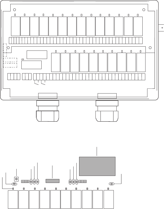
RECEIVER
____________________________________________
*
42 43 44 45 46 47 48 49 50 51 52 53 54 55 56 57 58 59 60 61 62 63 64 65 66 67 68 69 70 71 72 73 74 75 76 77 78 79 80 81 82 83
1 2 3 4 5 6 7 8 9 10 11 12 13 14 15 16 17 18 19 20 21 22 23 24 25 26 27 28 29 30 31 32 33 34 35 36 37 38 39 40 41
230 VAC
115 VAC
48 VAC
0 VAC
24 VAC
12 VAC
0 VAC
SR1 SR2
SR1
SR2
S1
* S3
* S2
860RX
1= Red LED 1
2= Yellow LED 2
3= Reset button
4= Green LED 4
5= Red LED 5
6= Yellow LED 6
7= Function selector switch
8= Green LED 8
9= Red LED 9
10= Yellow LED 10
11= Radio Module
12= Green LED 12
* Fuse S1, S2 and S3 ceramic slow.
S1 200 mA
S2 300-315 mA
S3 500 mA
2
34
5
6
7
1
8
9
10
11
12
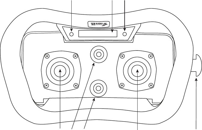
JOYSTICK
____________________________________________
DISPLAY
1 4 25
8
6
7
3
FRONT SIDE
1. Left joystick 3. Front switch 5. STOP button 7. Red/ green LED 2
2. Right joystick 4. Function switch 6. Red/ green LED 1 8. Display
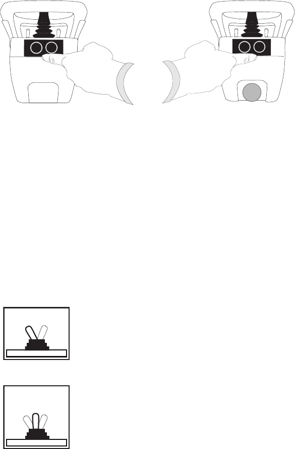
LEFT SIDE RIGHT SIDE
43
5
1 2
3. Button 3
4. Button 4
5. STOP button
1. Side button 1
2. Side button 2
FUNCTIONALITY OF THE 2 JOYSTICK SWITCHES
__________________________________________
FRONT SWITCH
2 steps (OFF/ON)
Toggling/latching relay function (i. e. spring loaded 2 step switch)
Starts up in OFF mode
FUNCTION SWITCH
3 steps switch
Selects functionality 1, 1+2, 2
OR 1,(NO FUNCTION), 2.
The switch function is toggling/ latching (i. e. the
functionality remains until the switch is being moved
again).The position of the function switch shows what
receiver, which group of relays or what lift on an
overhead crane that is currently under control
(not in joystick function selector mode 0).
1
1+2
/0
2

FREQUENCY TABLE (69 CHANNELS)
____________________________________________
CHANNEL FREQUENCY CHANNEL FREQUENCY
01 433,075 MHz 36 433,950 MHz
02 433,100 MHz 37 433,975 MHz
03 433,125 MHz 38 434,000 MHz
04 433,150 MHz 39 434,025 MHz
05 433,175 MHz 40 434,050 MHz
06 433,200 MHz 41 434,075 MHz
07 433,225 MHz 42 434,100 MHz
08 433,250 MHz 43 434,125 MHz
09 433,275 MHz 44 434,150 MHz
10 433,300 MHz 45 434,175 MHz
11 433,325 MHz 46 434,200 MHz
12 433,350 MHz 47 434,225 MHz
13 433,375 MHz 48 434,250 MHz
14 433,400 MHz 49 434,275 MHz
15 433,425 MHz 50 434,300 MHz
16 433,450 MHz 51 434,325 MHz
17 433,475 MHz 52 434,350 MHz
18 433,500 MHz 53 434,375 MHz
19 433,525 MHz 54 434,400 MHz
20 433,550 MHz 55 434,425 MHz
21 433,575 MHz 56 434,450 MHz
22 433,600 MHz 57 434,475 MHz
23 433,625 MHz 58 434,500 MHz
24 433,650 MHz 59 434,525 MHz
25 433,675 MHz 60 434,550 MHz
26 433,700 MHz 61 434,575 MHz
27 433,725 MHz 62 434,600 MHz
28 433,750 MHz 63 434,625 MHz
29 433,775 MHz 64 434,650 MHz
30 433,800 MHz 65 434,675 MHz
31 433,825 MHz 66 434,700 MHz
32 433,850 MHz 67 434,725 MHz
33 433,875 MHz 68 434,750 MHz
34 433,900 MHz 69 434,775 MHz
35 433,925 MHz

IMPORTANT INFORMATION
____________________________________________
READ THIS INFORMATION AND THE INSTRUCTIONS
CAREFULLY BEFORE ASSEMBLING, INSTALLING AND
PROGRAMMING TELE RADIO PRODUCTS.
Tele Radio cannot be held responsible for any damage or other
fault caused by a failure to follow the instructions. Failure to do so may invalidate
the warranty. These instructions contain information on the installation and
configuration of the remote radio control unit on the machine and are not
intended to be passed on to the end-user. The machine manufacturer is obliged to
produce an operating guide for the machine, which also describes the safe and
appropriate operation by remote radio control. Only such information that the
end-user needs to operate the machine by remote control should be passed on.
IT IS YOUR RESPONSIBILITY TO FIND OUT ABOUT
THE LAWS AND REGULATIONS
THAT APPLY IN YOUR
COUNTRY / STATE / CITY AND COUNTY!
SAFETY INSTRUCTIONS
This product should only be installed by licensed or qualified personnel.
Switch the power supply to the receiver off before connecting the equipment.
Turn off the transmitter when not in use.
Keep a clear view of the work area.
Make sure to use undamaged cables. Make sure that cables do not hang loose.
Avoid installing the product in areas affected by strong vibrations.
Allow only qualified and trained personnel to operate or have access to
transmitter.
Do not leave the transmitter unsupervised.
Contact your dealer for repair and maintenance work on the product.
Retain instructions for future reference and re-programming of the system.
Visit our website for FAQ & the latest information:
www.tele-radio.com
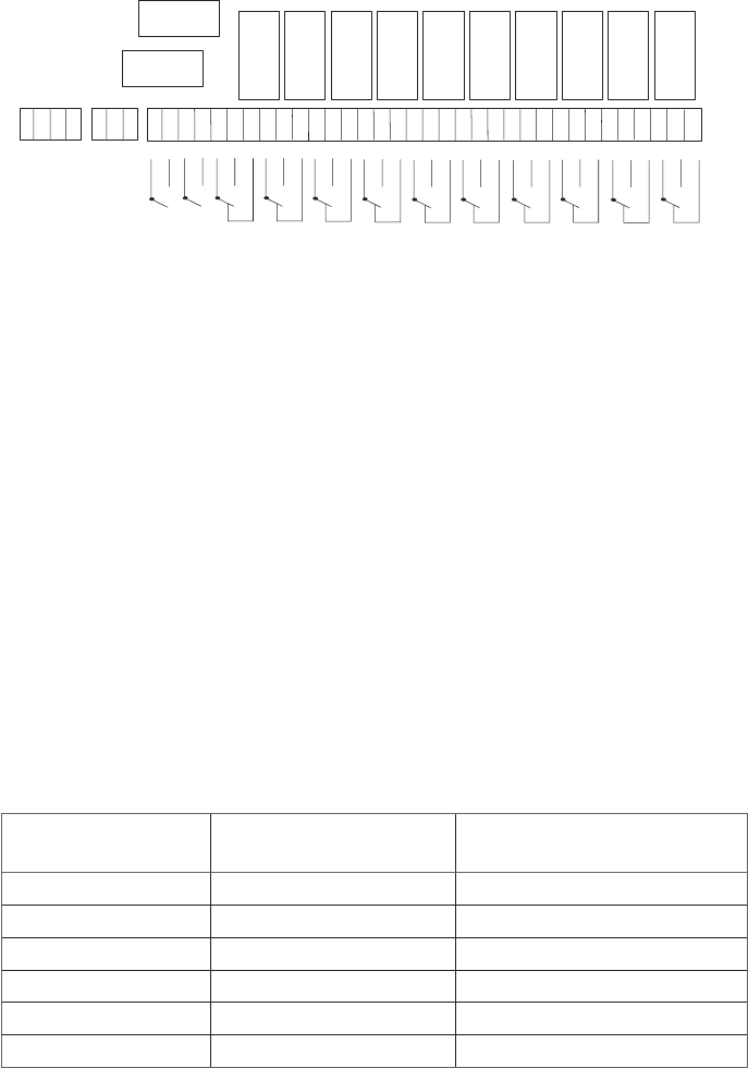
THE RECEIVER 860RX
___________________________________________
TECHNICAL DATA
RELAY OUTPUTS: MIDI: 10 + 2 for STOP function
MAXI: 24 + 2 for STOP function
STOP RELAYS: Potential free*, makes/ breaks 16A ACI
FUNCTION RELAY: Potential free*, makes/ breaks 16A ACI
OPERATING FREQUENCY: 433.075-434.775 MHz.
CHANNELS: 69
SIZE: 256 x 217 x 85 mm.
WEIGHT: 1900 - 2100 g.
DEGREE OF PROTECTION: IP65
*potential-free means that you need to supply voltage to get power out of a relay
(e.g. via a connection comb).
IMPORTANT! To utilize the safety, relays SR1 and SR2 shall be used as
stop relays in the safety circuitry of the object to be controlled.
SUPPLY VOLTAGE MIN. POWER
CONSUMPTION:
MAX. POWER
CONSUMPTION:
12V DC 150 mA. 1 A.
24V DC 60 mA. 600 mA.
24V AC 80 mA. 800 mA.
48V AC 100 mA. 400 mA.
115V AC 70 mA. 200 mA.
230V AC 25 mA. 100 mA.
123
SR1
SR2
4 5
6
7 8 9 10
8 9 10 11 12 13 14 15 16 17 18 19 20 21 22 23 24 25 26 27 28 29 30 31 32 33 34 35 36 37 38 39 40 41
1 2 3 4 5 6 7
230VAC
115VAC
48 VAC
0 V
24V AC/DC
12V DC
0 V
C NO NC C NO NCC NO NC CNO NC C NO NC C NO NC C NO NC
SR2
1234 5 6
SR1
C NO NC C NO NC C NO NC
78 9 10

PLACE THE RECEIVER
Well away from wind, damp and water.
Cable holders and vent plugs must face down to prevent water from
seeping in.
If the receiver is to be placed in a a hard-to-reach place, it is advisable
to complete the settings in the receiver before mounting it.
Place receiver as high as possible off the ground.
Place receiver in as free position as possible.
Well away from metal objects, such as metal girders, high-voltage
cables and other antennas.
PLACE THE ANTENNA
Check that there is a good connection between the antenna and the
material on which it has been installed, e.g. after repainting of the
chassis.
Check that the antenna aerial and any coaxial cables are undamaged.
Check that the antenna is directed upwards.
The 1/2-wave antenna is ground plane independent. If the receiver is
installed on a wall, the antenna should be angled out from the wall
The 1/4-433K antenna with a 3 metres coaxial cable for high and
XQREVWUXFWHGSODFHPHQW)RURSWLPXPUDQJHLQVWDOORQDÁDWURRIIUHH
from other metal objects and antennas. When installing the antenna
on a vehicle, use a vehicle bracket (F1).
The 5/8-wave antenna with a 3 metres coaxial cable for high and
XQREVWUXFWHGSODFHPHQW)RURSWLPXPUDQJHLQVWDOORQDÁDWURRIIUHH
from other metal objects and antennas. When installing the antenna
on a wall, use a wall bracket (VM1).
1/2
1/4-433K
5/8
JOYSTICK TRANSMITTER
____________________________________________
TECHNICAL DATA
860TX4-A
JOYSTICK FUNCTIONS: Left 4x4, right 0x4
DEGREE OF PROTECTION: IP 65
OPERATING FREQUENCY: 433.075-434.775 MHz
CHANNELS: 69
SIZE: 145 mm. x 210 mm. x 130 mm.
WEIGHT: 1200 g.
BATTERY: 1 external, rechargeable battery (li-ion)
860TX4-B
JOYSTICK FUNCTIONS: Left 2x2, right 0x2
DEGREE OF PROTECTION: IP 65
OPERATING FREQUENCY: 433.075-434.775 MHz
CHANNELS: 69
SIZE: 145 mm. x 210 mm. x 130 mm.
WEIGHT: 1200 g.
BATTERY: 1 external, rechargeable battery (li-ion)
HOW TO START UP IN OPERATING MODE
1. Pull out the STOP button.
The green/red LEDs 1+2 light up. Green when battery capacity is good, red when the battery needs to
be charged. See how to charge the battery in “Battery- how to charge”.
2. Press the side buttons 3+4 for about 0.30 seconds until LEDs 1+2 go out.
The buzzer sounds.
HOW TO TURN OFF
1. Press the STOP button. The joystick is now turned off.
LED 1+ LED 2 light red for approx. 3 seconds.
NOTE! All relays disconnect when the STOP button is pressed.
HOW TO REGISTER THE JOYSTICK IN THE RECEIVER
The receiver can store up to 3 different transmitters.
Each transmitter has a unique code.
Receiver-LEDs 6 and 10 indicate the number of transmitters that are registered
in the receiver.
1RWÁDVKLQJ No transmitter/ joystick is registered
ÁDVK 1 transmitter/joystick is registered
ÁDVKHV 2 transmitter/joysticks are registered
ÁDVKHV 3 transmitter/joysticks are registered
1. Turn the receiver Function selector switch 2 to ON position.
2. Press the receiver Reset button.
Receiver LEDs 4,5, 6, 8, 9 and10 light up.
3. Release the receiver Reset button.
Receiver LEDs 4, 8, 5 and 9 go out. Yellow receiver LEDs 6 and 10 light up when the receiver is ready to
register.
127(,IWKH\HOORZDQGUHGUHFHLYHU/('VÁDVKDOWHUQDWLQJWKHPD[LPXPQXPEHURIWUDQVPLWWHUVMR\VWLFNV
have already been registered in the receiver.
4. Start up the joystick in operating mode.
5. Press the joystick side buttons 2+4 at the same time. Keep pressed until the
\HOORZUHFHLYHU/('VDQGVWDUWWRÁDVK
6. Turn the receiver Function selector switch 2 to OFF position.
7KHMR\VWLFNLVQRZUHJLVWHUHGLQWKHUHFHLYHU
7. Write down the new settings in the Settings document (download and print
from the Tele Radio website)
IMPORTANT! For safety reasons, avoid storing transmitters in receivers,
where you don´t intend to use it.
HOW TO ERASE ALL JOYSTICKS FROM THE RECEIVER
127(<RXKDYHWRHUDVHDOOUHJLVWHUHGWUDQVPLWWHUVZKHQHUDVLQJRQH
1. Turn the receiver Function selector switch 2 to ON position.
2. Press the receiver Reset button.
The receiver LEDs 4, 5, 6, 8, 9 and 10 light continuously.
3. Release the receiver Reset button.
All LEDs go out, except for the receiver LEDs 6, and 10.
4. Turn the receiver Function selector switch 2 to OFF position. PERFORM THE
NEXT STEP WITHIN 2 SECONDS:
5. Turn the receiver Function selector switch 2 to ON position.
7KHUHFHLYHU/('VDQGÁDVK
6. Turn the receiver Function selector switch 2 to OFF position.
$OOUHJLVWHUHGWUDQVPLWWHUVDUHQRZHUDVHGIURPWKHUHFHLYHU
HOW TO LOG IN/ LOGOUT THE JOYSTICK
When you start up a registered transmitter, it logs in to the receiver. The receiver
will only accept this transmitter (even though other transmitters may be registered
in the receiver) until it´s being logged out. If you want to use another transmitter,
you have to log out the transmitter from the receiver.
1. The joystick, that is logged in, must be in operating mode.
2. Press button 4.
3. Without releasing button 4, press the STOP button.
4. The display shows the text “Log out” and the transmitter turns itself off. The
transmitter is now logged out. When you start a registered transmitter, it will
now automatically log in to the receiver.
SETTINGS MENU
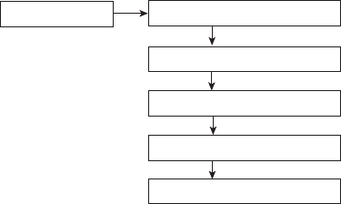
SETTINGS MENU MAP
CHANNEL
BRIGHTNESS
SETTINGS MENU
BACKLIGHT TIME
AUTO SHUTDOWN
REPLACE TRANSMITTER
HOW TO NAVIGATE IN THE SETTINGS MENU
TO MOVE UP AND DOWN: Use the left joystick.
TO SELECT: Use button 4.
TO GO BACK: Use the left joystick.
TO EXIT: Press button 3 or pull out the STOP button. The transmitter
will turn off.

HOW TO START UP IN MENU MODE
1. Pull out the STOP button.
The LEDs 1+2 light green when battery capacity is good, red when battery needs to be
charged. See how to charge the battery in the section Battery- how to charge.
2. Press button 3 and keep pressed.
3. Press the STOP button while still pressing button 3.
/('VWDUWVÁDVKLQJ
4. Release button 3.
/('JRHVRXWDQGWKH6HWWLQJVPHQXVKRZVLQWKHGLVSOD\
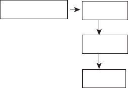
HOW TO SWITCH CHANNEL
Channel 69...
CHANNEL
...channel 1
Go to the frequency table in the beginning of the installation instruction. The
joysticks are pre-programmed to transmit at various frequencies.
1. Pull the STOP button. Enter the Settings menu by pressing button 3. Keep it
pressed.
2. :LWKRXWUHOHDVLQJEXWWRQSUHVVWKH6723EXWWRQXQWLO/('VWDUWVWRÁDVK
7KH6HWWLQJPHQXVKRZVLQWKHGLVSOD\
3. Select Channel in the Settings menu by pressing button 4.
4. Move up and down with the left joystick. Keep pressed to move several steps.
5. Select by pressing button 4.
<RXZLOOJHWEDFNWRWKHPHQXDIWHUVHOHFWLQJ
6. To leave the Settings menu, press button 3.
7KHWUDQVPLWWHUWXUQVLWVHOIRII
:KHQ\RXUHVWDUWWKHMR\VWLFNLWZLOOWUDQVPLWDWWKHQHZIUHTXHQF\7KHUHFHLYHUZLOODXWRPDWLFDOO\
GHWHFWDQGVZLWFKWRWKHQHZIUHTXHQF\
7. Write down the new settings in the Settings document (download and print
from the Downloads page at the Tele Radio website).
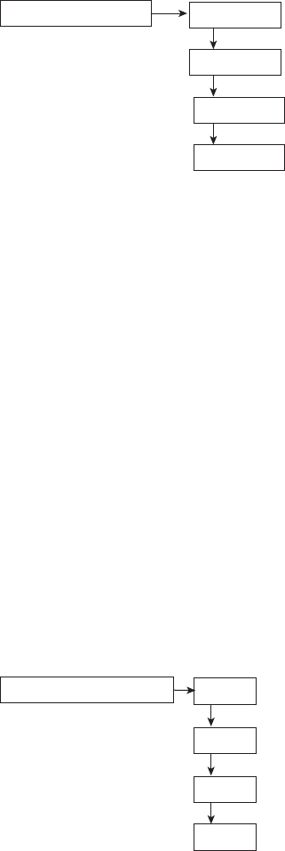
HOW TO CHANGE THE BACKLIGHT BRIGHTNESS
BRIGHTNESS High
Medium
Low
1. Pull the STOP button. Enter the Settings menu by pressing button 3. Keep it
pressed.
2. :LWKRXWUHOHDVLQJEXWWRQSUHVVWKH6723EXWWRQXQWLO/('VWDUWVWRÁDVK
7KH6HWWLQJPHQXVKRZVLQWKHGLVSOD\
3. Navigate to Brightness with the left joystick. Select by pressing button 4.
4. Move up and down with the left joystick. Select by pressing button 4.
<RXZLOOJHWEDFNWRWKHPHQXDIWHUVHOHFWLQJ
5. To leave the Settings menu, press button 3.
7KHMR\VWLFNWXUQVLWVHOIRII
6. When you re-start the joystick, the new settings will be activated.
HOW TO CHANGE THE BACKLIGHT TIME
BACKLIGHT TIME Always on
Off in 30 sec.
Off in 10 sec.
Always off
1. Pull the STOP button. Enter the Settings menu by pressing button 3. Keep it
pressed.
2. :LWKRXWUHOHDVLQJEXWWRQSUHVVWKH6723EXWWRQXQWLO/('VWDUWVWRÁDVK
7KH6HWWLQJPHQXVKRZVLQWKHGLVSOD\
3. Navigate to %DFNOLJKW7LPHwith the left joystick. Select by pressing button 4.
4. Move up and down with the left joystick. Select by pressing button 4.
<RXZLOOJHWEDFNWRWKHPHQXDIWHUVHOHFWLQJ
5. To leave the Settings menu, press button 3.
7KHMR\VWLFNWXUQVLWVHOIRII
6. When you re-start the joystick, the new settings will be activated.
HOW TO CHANGE THE AUTOMATIC SHUTDOWN SETTINGS
AUTOMATIC SHUTDOWN OFF
12 min.
6 min.
2 min.
Automatic shut down helps preserving the battery capacity. The joystick will shut
down at a given time after the last command has been sent.
1. Pull the STOP button. Enter the Settings menu by pressing button 3. Keep it
pressed.
2. :LWKRXWUHOHDVLQJEXWWRQSUHVVWKH6723EXWWRQXQWLO/('VWDUWVWRÁDVK
7KH6HWWLQJPHQXVKRZVLQWKHGLVSOD\
3. Navigate to $XWRPDWLF6KXWGRZQwith the left joystick. Select by pressing button
4.
4. Move up and down with the left joystick. Select by pressing button 4.
<RXZLOOJHWEDFNWRWKHPHQXDIWHUVHOHFWLQJ
5. To leave the Settings menu, press button 3.
7KHMR\VWLFNWXUQVLWVHOIRII
6. When you re-start the joystick, the new settings will be activated.
7. Write down the new settings in the Settings document (download and print
from the Downloads page at the Tele Radio website).
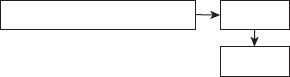
HOW TO REPLACE A TRANSMITTER
REPLACE TRANSMITTER No
Yes
Use the transmitter that you want to register in the receiver. You will need the ID
code (serial no) for the transmitter that you want to replace. The ID code (serial no)
is found on a label behind the battery.
1. Pull the STOP button. Enter the Settings menu by pressing button 3. Keep it
pressed.
2. :LWKRXWUHOHDVLQJEXWWRQSUHVVWKH6723EXWWRQXQWLO/('VWDUWVWRÁDVK
SETTINGS DOCUMENT
Download for print at: www.tele-radio.com
JOYSTICK 1
Article no:_________________________________Series no: ________________________ID
code : ___________________________________________________________________
Automatic shutoff: ___________________________________________________________
Function selector: __________________________________________________________
Frequency:_________________________________________________________________
Latching relays:______________________________________________________________
Interlocking relays: ___________________________________________________________
PIN-position PIN-code/Name
1_______ ______________________________
2_______ ______________________________
3_______ ______________________________
4_______ ______________________________
5_______ ______________________________
6_______ ______________________________
7_______ ______________________________
8_______ ______________________________
9_______ ______________________________
0_______ ______________________________
JOYSTICK 2
Article no:_________________________________Series no: ________________________ID
code : ___________________________________________________________________
Automatic shutoff: ___________________________________________________________
Function selector: __________________________________________________________
Frequency:_________________________________________________________________
Latching relays:______________________________________________________________
Interlocking relays: ___________________________________________________________
PIN-position PIN-code/Name
1_______ ______________________________
2_______ ______________________________
3_______ ______________________________
4_______ ______________________________
5_______ ______________________________
6_______ ______________________________
7_______ ______________________________
8_______ ______________________________
9_______ ______________________________
0_______ ______________________________
RADIO TRANSMISSION
THE JOYSTICK 1
The left joystick (JD1) can be moved in all directions. It transmits radio continuously
at the selected channel when being pressed. When released, the radio stops transmit-
ting within 5 seconds.
THE JOYSTICK 2
The right joystick (JD2) can be moved upwards and downwards. It transmits radio
continuously at the selected channel when being pressed. When released, the radio
stops transmitting within 5 seconds.
THE FRONT SWITCH
The Front switch can be placed in 2 positions:
LEFT: OFF
RIGHT: ON
The switch is toggling and will keep the position until being switched again, but it
always starts up in OFF position. It transmits radio continuously when being pressed.
When released, the radio stops transmitting within 5 seconds. The Front switch
activates relay 24 in some receiver Function selections. The relay will be activated
until the switch is being moved again.
THE FUNCTION SWITCH
The Function switch is used for selecting what receiver(s) to control. It can be placed
in 3 positions:
LEFT: 1
MID: 1+2 (or 0)
RIGHT: 2
OFF ON
1
(1+2) / 0
2
What positions that are available, depends on what joystick function selection that
has been chosen. The switch does not transmit radio at any position. The switch is
toggling, and will keep the position until being switched again.
Function selection 0
In this Function selection you can only control 1 receiver. The Function switch is not
used and can be put in any position.
Function selection 1
Note that this Function selection lets you control up to 2 receivers at the same time.
Put the Function switch in position 1 when you want to control the 1st receiver.
Put the Function switch in position 1+2 when you want to control 2 receivers at the
same time.
Put the Function switch in position 2 when you want to control the 2nd receiver.
Function selection 2
Note that this Function selection lets you control up to 2 receivers, but NOT at the
same time.
Put the Function switch in position 1 when you want to control the 1st receiver.
Put the Function switch in position 0 if you don´t want to control any receiver.
Put the Function switch in position 2 when you want to control the 2nd receiver.
BATTERY
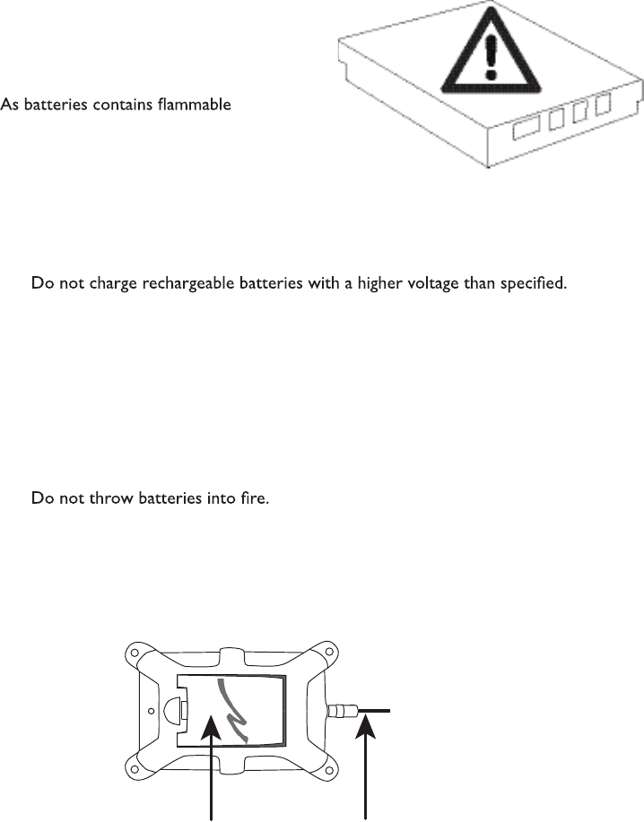
PRECAUTIONS
Observe the following warnings.
substances such as lithium or other organic
solvents, they may cause heating, rupture or
ignition.
Risk of explosion if battery is replaced with a battery of an incorrect type.
Do not short circuit, disassemble, deform or heat batteries.
Never try to charge a visibly damaged or frozen battery.
Keep batteries out of reach of small children. Should a child swallow a battery,
consult a physician immediately.
Avoid direct soldering to batteries.
When discarding batteries, insulate the + and - terminals of batteries with insulating/
masking tape. Do not put multiple batteries in the same plastic bag.
When improperly disposed, lithium batteries may short circuit, causing them to
become hot, burst or ignite.
Store in a cool location. Keep batteries away from direct sunlight, high temperature,
and high humidity.
HOW TO CHARGE
BATTERY TYPE: External and rechargeable lithium-ion
CHARGE: In the charger unit 5V DC ±10% (1A)
CHARGING TEMPERATURE: 0°C to 45°C/ 32°F to 113°
OPERATING TIME: Approx. 15 h. with continuous usage
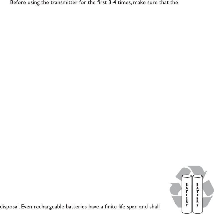
battery is fully charged.
When it´s time to charge the battery, the internal buzzer beeps 3 times, and LED 1
+ 2 turn red.
The battery can not be overcharged.
The display monitors the battery status.
We recommend that you use your battery at least once a month. If you for some
reason won´t use it for a longer period, store in a cool, dry and clean place. Before
starting to use the battery again, make sure that it is fully charged.
NOTE! The transmitter must be on to check the battery status.
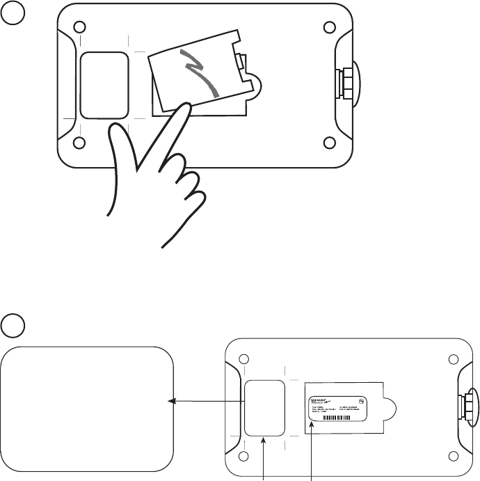
PLACEMENT OF BATTERIES
The battery is placed on the bottom of the joystick.
DISPOSAL OF BATTERIES
A lithium-ion battery does not contain mercury,
cadmium or lead and is better for the environment than older
types of batteries. Rechargeable batteries last considerably longer
than single-use batteries, so using them means fewer batteries for
be recycled. Contact your local government’s recycling or solid
waste department for more information on proper recycling of
lithium-ion batteries in your region.
B
A
T
T
E
R
Y
B
A
T
T
E
R
Y
This ecived seilpmoc with trap
t
arepO
.seluRCC
F
eh
tfo51 ion
is tc
e
jbu
sto eht gniw
o
llof two
:sn
oitid
noc )1( This ec
ived may
,
ecne
refretn
il
ufmrahes
uacton
dna )
2( siht ec
ived tsum tpe
c
ca
na y cne
re
fretni e ,
d
evie
c
er
ya
m
t
ahtecne
r
efre
tn
ignidu
l
cn
i
o
i
tarepoderisednuesua
c n.
1.
2.
Remove the battery from the bottom of the joystick.
PLACEMENT OF LABELS WITH IC AND FCC
INFORMATION
The FCC statement is placed to the left.The product label is placed behind the
battery in the battery compartment on the bottom of the joystick transmitter.
Product label with IC and FCC ID
FCC label
This device complies with part
15 of the FCC Rules. Operation
is subject to the following two
conditions: (1) This device may
not cause harmful interference,
and (2) this device must accept
any i nterference r eceived,
including interference that may
cause undesired operation.
**
This eci
ved seil
p
mo
c with trap
noit
are
pO
.seluRCC
Fehtfo51
is t
cejbus to eht gn
iwollof two
:
snoitidno
c )1( This ecived may
,ecn
erefr
etnilu
fmr
ahe
sua
cto
n
d
na )2( sih
tt
sumeciv
ed tpe
c
ca
n
ay c
n
erefretni e de
v
ie
cer ,
y
amtahte
c
nerefretni
g
nidulcni
.n
o
itar
epod
eri
sednue
s
ua
c
GUARANTEE
Tele Radio’s products are covered by a
guarantee against material, construction
or manufacturing faults. During the
guarantee period Tele Radio may replace
the product or faulty parts with new
ones.Work under guarantee must be
carried out by Tele Radio or by an
Tele Radio.The following faults are not
covered by the warranty:
Faults resulting from normal wear
and tear.
Parts of a consumable nature.
Products that have been subject to
Faults resulting from incorrect
installation or use.
Damp or water damage.
SERVICING & REPAIRS
Make sure that repairs and maintenance
personnel. Only use spare parts from
Tele Radio. Contact your dealer if you
want to make a complaint about a
product or require other service.Always
have the following details to hand when
you contact a dealer about a complaint
or service issue: Name of the system,
model and a description of the problem.
If you need to return a product, the
invoice number and delivery date should
be included.
OPERATING GUIDELINES
Keep the product in a dry, clean place.
Make sure that contacts and antennas
are kept clean.Wipe off dust using a
slightly damp, clean cloth. Never use
cleaning solutions or high-pressure
water.
FCC STATEMENTS
THIS DEVICE COMPLIES WITH PART 15 OF THE
FCC RULES. OPERATION IS SUBJECT TO THE
FOLLOWING TWO CONDITIONS:
1.THIS DEVICE MAY NOT CAUSE HARMFUL
INTERFERENCE
2.THIS DEVICE MUST ACCEPT ANY
INTERFERENCE THAT MAY CAUSE UNDESIRED
OPERATION.
NOTE:THE MANUFACTURER IS NOT
RESPONSIBLE FOR ANY RADIO OR TV
INTERFERENCE CAUSED BY UNAUTHORIZED
MODIFICATIONS TO THIS EQIPMENT. SUCH
MODIFICATIONS COULD VOID THE USER´S
AUTHORITY TO OPERATE THE EQUIPMENT.

TELE RADIO SVERIGE
Sweden
Tel. +46 (0)31-724 98 00
e-mail: sverige@tele-radio.com
TELE RADIO GmbH
Germany
Tel. +49 (0)94 51-944 8 550
e-mail: deutschland@tele-radio.com
TELE RADIO ASIA
China
Tel. +86-(0)592-3111168
e-mail: china@tele-radio.com
TELE RADIO LTD
England
Tel. +44 (0) 1625 509125
e-mail: england@tele-radio.com
TELE RADIO OÜ
Estonia
Tel. +372 44 511 55
e-mail: eesti@tele-radio.com
TELE RADIO LLC
North America & Latin America
Tel. +1 (305) 459 0763
e-mail: america@tele-radio.com
TELE RADIO BV
Benelux
Tel. +31-(0)70-419 41 20
e-mail: benelux@tele-radio.com
TELE RADIO AS
Norway
Tel. +47-6933 4900
e-mail: norge@tele-radio.com
TELE RADIO AB
Sweden, Main office
Tel. +46 (0)31-748 54 60
e-mail: info@tele-radio.com www.tele-radio.com
TELE RADIO TURKEY
Turkey
Tel. +90 216 574 22 94
e-mail: turkiye@tele-radio.com