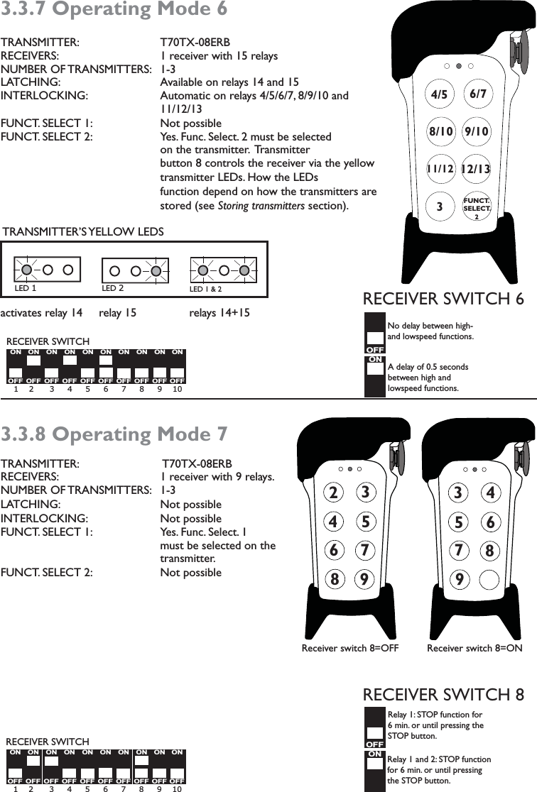
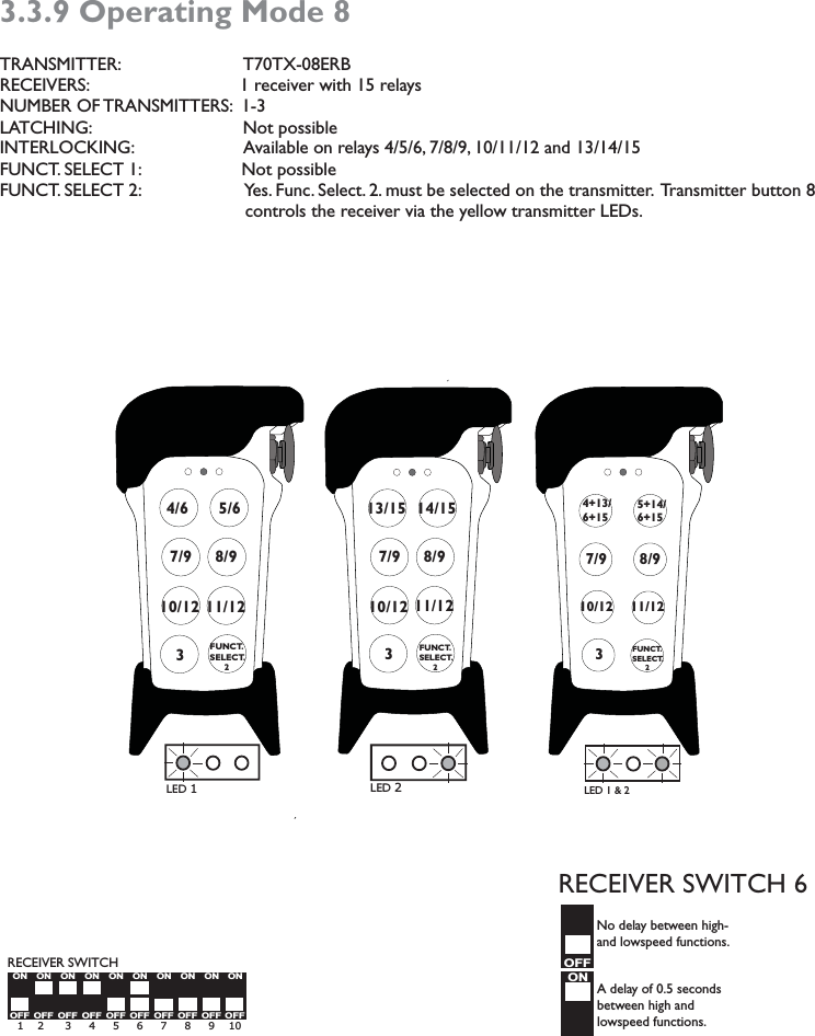
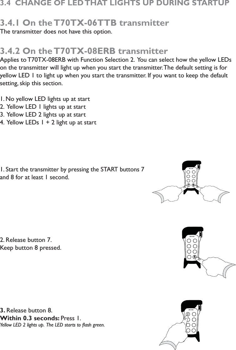
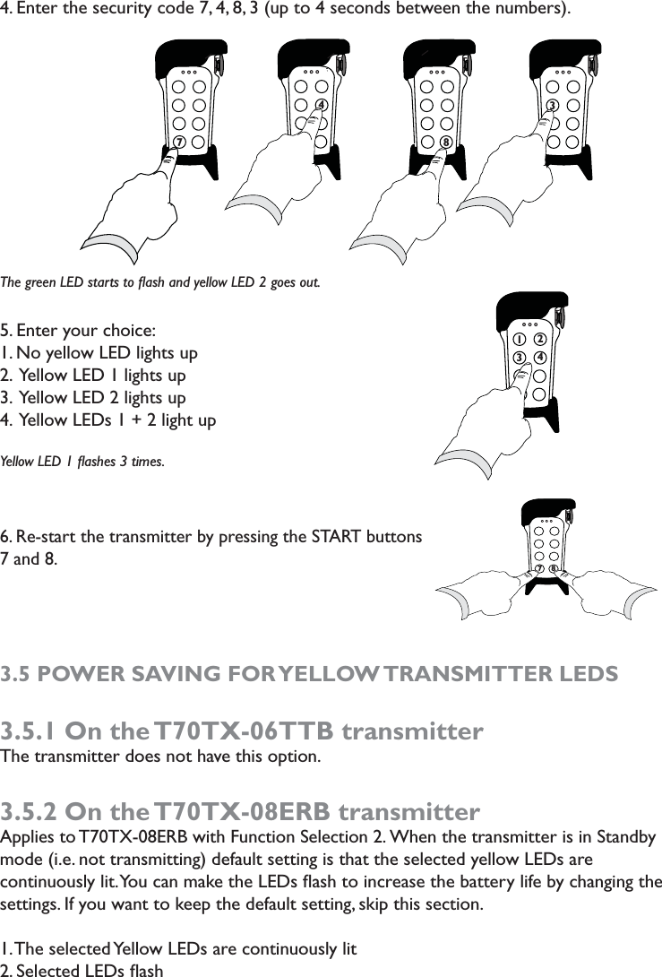
Tele Radio T70TX-08ERB Transmitter T70TX User Manual orig EN jag indd
Tele Radio AB Transmitter T70TX orig EN jag indd
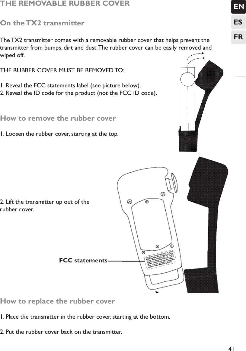
UserManual.wiki
>
Tele Radio
>
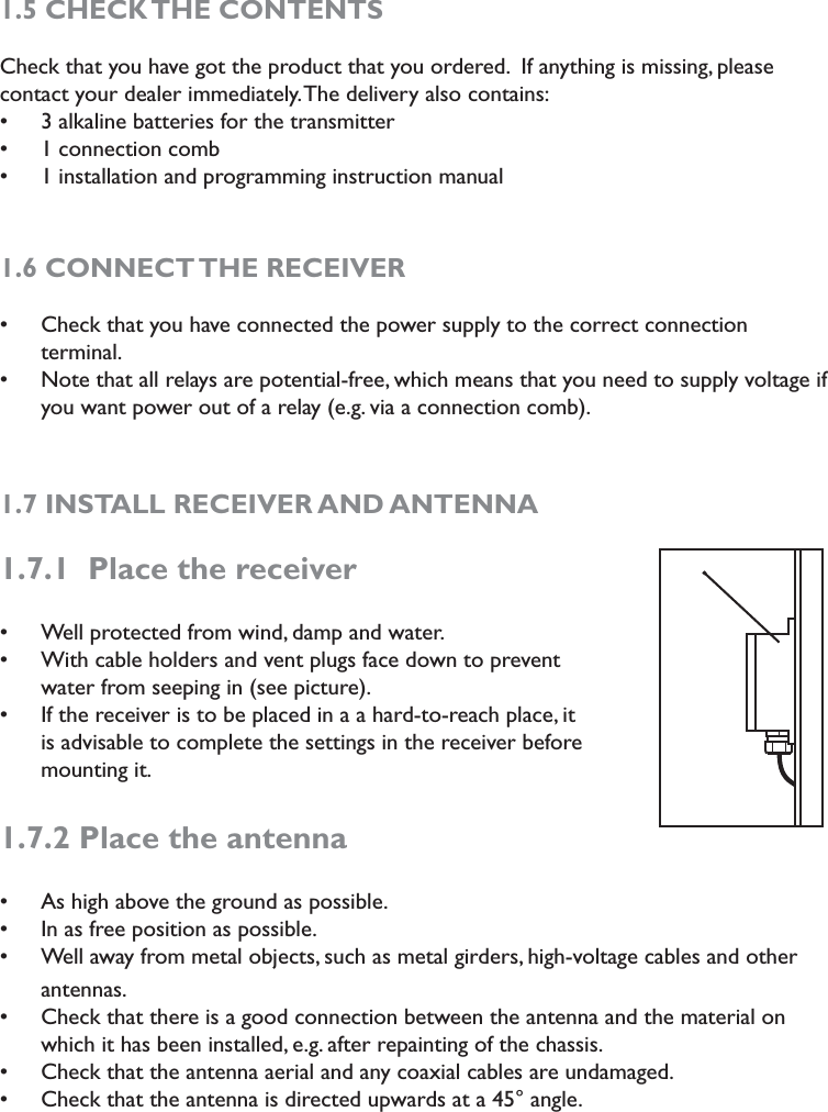
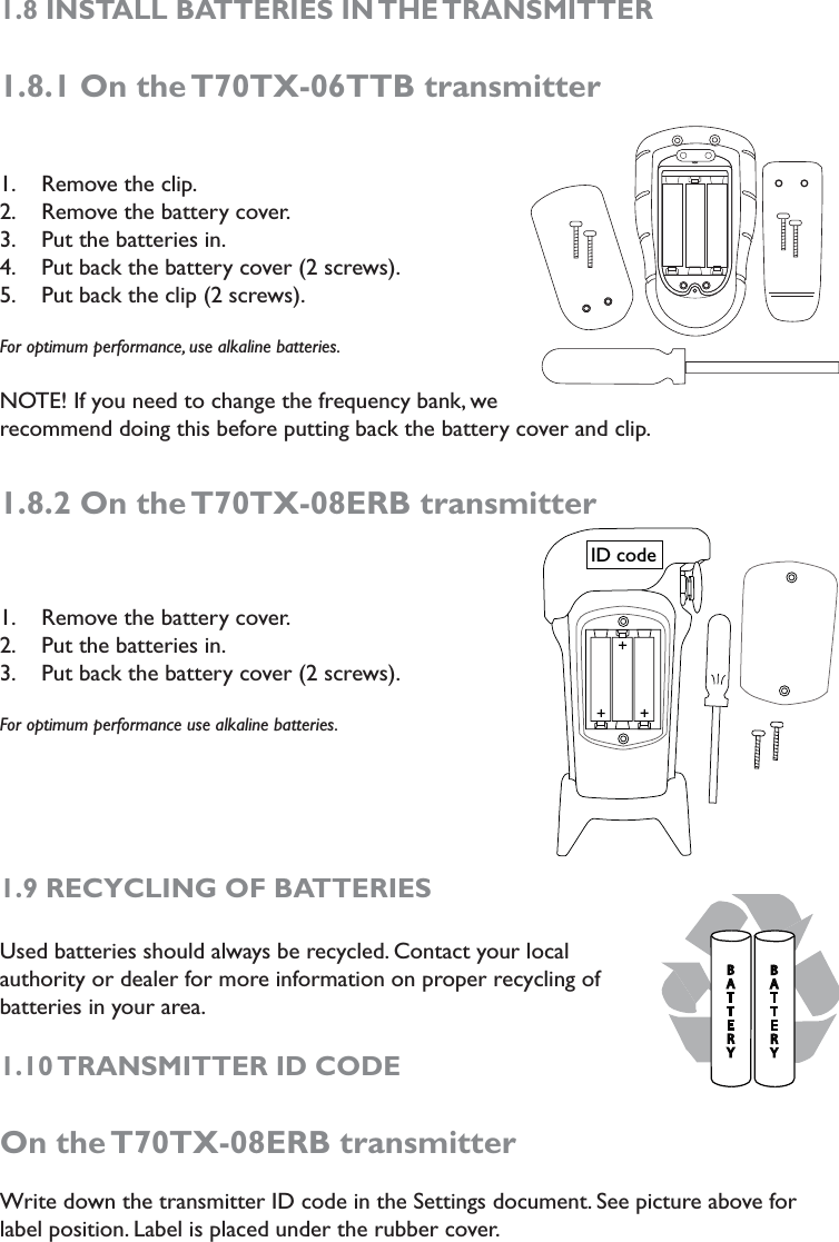
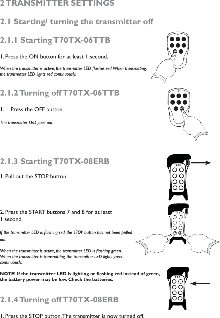
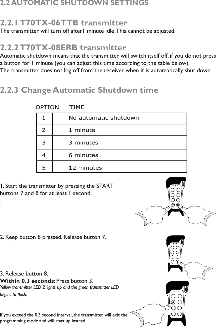
T70TX 08ERB User Manual
manual
Navigation menu
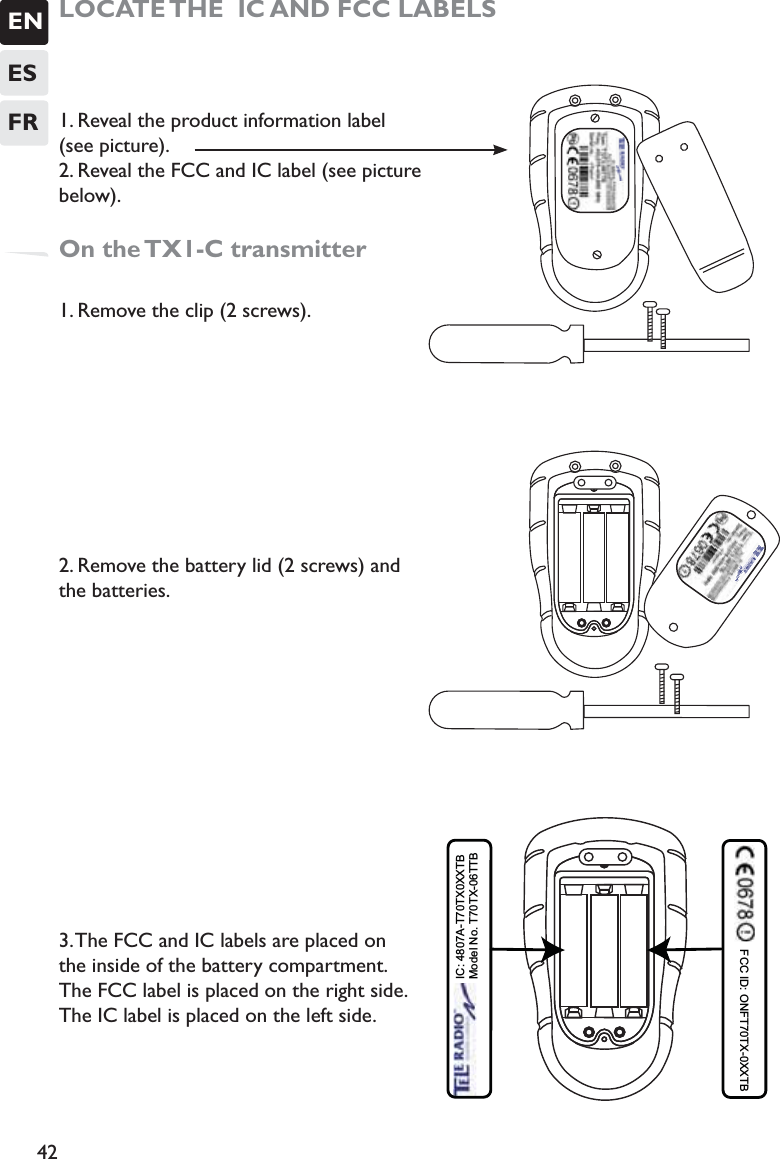
Upload a User Manual
Namespaces
Wiki Guide
HTML
PDF
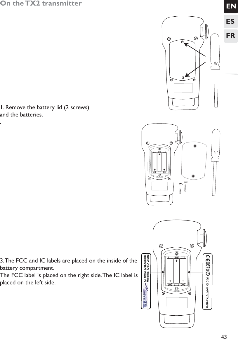
Info
Views
User Manual
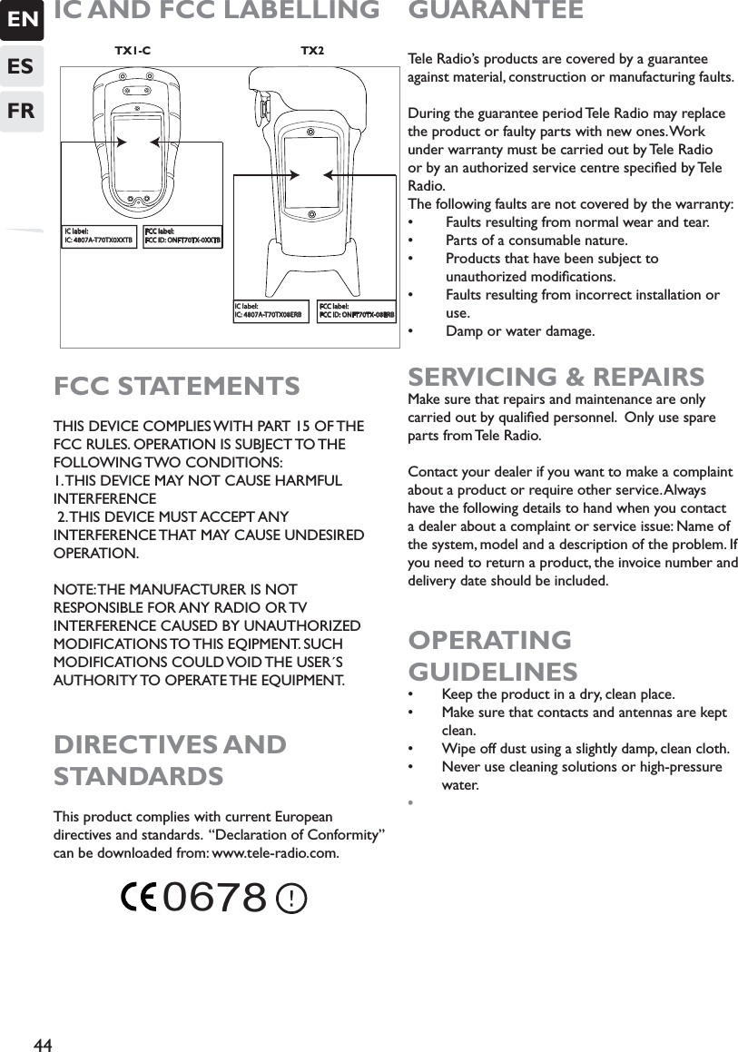
Discussion / Help
Navigation