Tele Radio T70TX-08ERB Transmitter T70TX User Manual orig EN jag indd
Tele Radio AB Transmitter T70TX orig EN jag indd
manual

Tele Radio Jaguar
MANUAL
Rev. IM-T70-003-A1
CONTENTS
TELE RADIO
SETTINGS DOCUMENT
Download for print at: www.tele-radio.com
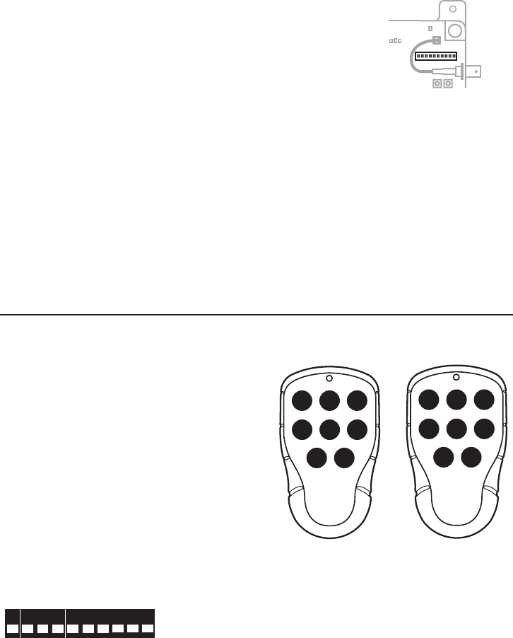
TRANSMITTER(S)
TRANSMITTER 1
Article no:_______________________________Series no: _______________________________
ID code (T70TX-08ERB): ________________________
Automatic shutoff: ______________________________
Operating Mode: _______________________________
Function Selection: 1 2
TRANSMITTER 2
Article no:_______________________________Series no: _______________________________
ID code (T70TX-08ERB): ________________________
Automatic shutoff: ______________________________
Operating Mode: _______________________________
Function Selection: 1 2
TRANSMITTER 3
Article no:_______________________________Series no: _______________________________
ID code (T70TX-08ERB): ________________________
Automatic shutoff: _______________________________
Operating Mode: ________________________________
Function Selection: 1 2
RECEIVER(S)
RECEIVER 1
Article no:_______________________________Series no: _______________________________
Latching relays: __________________________________________________________________
Interlocking relays: _______________________________________________________________
Stored transmitter(s). Series no for T70TX-06TTB/ ID code for T70TX-08ERB:
1. _________________________2. _________________________3. _______________________
RECEIVER 2
Article no:_______________________________Series no: _______________________________
Latching relays: __________________________________________________________________
Interlocking relays: _______________________________________________________________
Stored transmitter(s). Series no for T70TX-06TTB/ ID code for T70TX-08ERB:
1. _________________________2. _________________________3. _______________________

CHANNEL FREQ.BANK 1 OPTION
1 433.075 111
2 433.175 112
3 433.275 113
4 433.375 114
5 433.475 115
6 433.575 116
7 433.675 117
8 433.775 118
9 433.875 121
10 433.975 122
11 434.075 123
12 434.175 124
13 434.275 125
14 434.375 126
15 434.075 127
16 434.075 128
CHANNEL FREQ.BANK 2 OPTION
1 433.100 211
2 433.200 212
3 433.300 213
4 433.400 214
5 433.500 215
6 433.600 216
7 433.700 217
8 433.800 218
9 433.900 221
10 434.000 222
11 434.100 223
12 434.200 224
13 434.300 225
14 434.400 226
15 434.500 227
16 434.600 228
CHANNEL FREQ.BANK 3 OPTION
1 433.125 311
2 433.225 312
3 433.325 313
4 433.425 314
5 433.525 315
6 433.625 316
7 433.725 317
8 433.825 318
9 433.925 321
10 434.025 322
11 434.125 323
12 434.225 324
13 434.325 325
14 434.425 326
15 434.525 327
16 434.625 328
CHANNEL FREQ.BANK 4 OPTION
1 433.150 411
2 433.250 412
3 433.350 413
4 433.450 414
5 433.550 415
6 433.650 416
7 433.750 417
8 433.850 418
9 433.950 421
10 434.050 422
11 434.150 423
12 434.250 424
13 434.350 425
14 434.450 426
15 434.550 427
16 434.650 428
FREQUENCY BANK
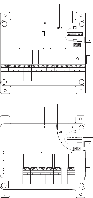
T70RX-09SB
the yellow power supply LED1.
the red CODE STORING LED2.
the yellow LATCH LED3.
the green INTERLOCKING LED4.
LOGOUT LED5.
Receiver switch6.
Antenna connector7.
FUNCTION button8.
SELECT button9.
321 456789
48-230
VAC
12-24
VAC/DC
RELAY 1
RELAY 2
RELAY 3
RELAY 4
RELAY 5
RELAY 6
RELAY 7
RELAY 9
RELAY 8
11 15
10 12 13 14
1
2
3
45
6
7
9
8
321 456789
48-230
VAC
12-24
VAC/DC
1
2
3
45
6
7
9
8
T70RX-15SB
the yellow power supply LED 1.
the red CODE STORING LED2.
the yellow LATCH LED3.
the green INTERLOCKING LED4.
LOGOUT LED5.
Receiver switch6.
Antenna connector7.
FUNCTION button8.
SELECT button9.
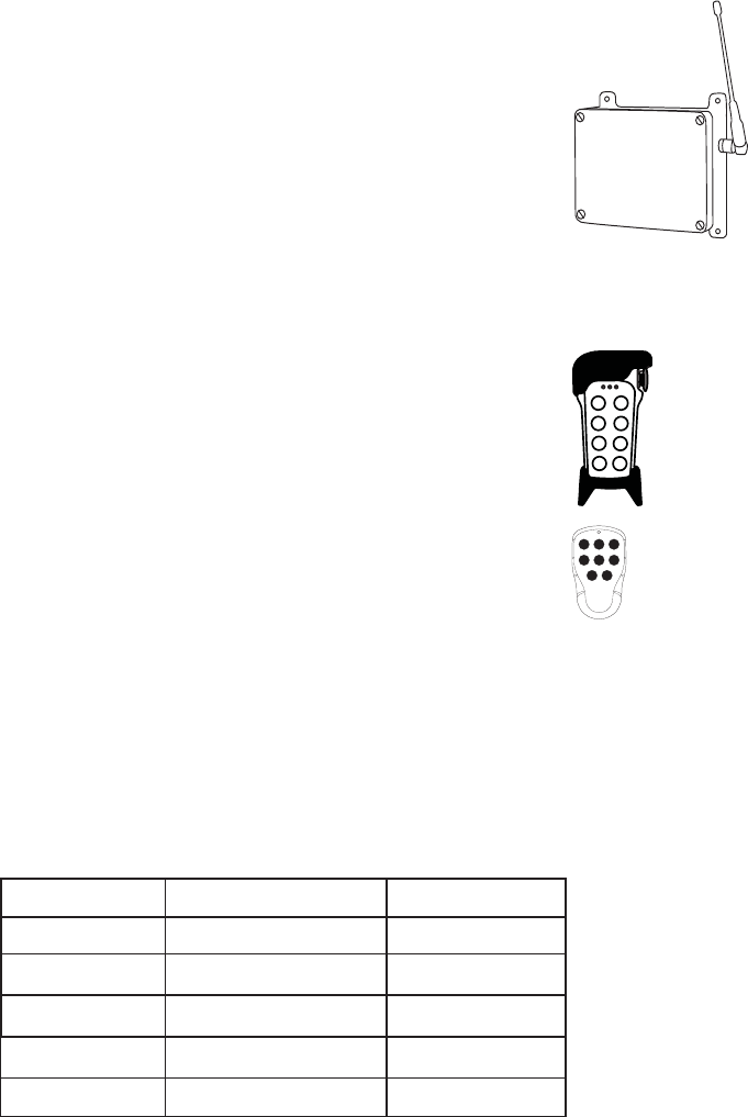
RECEIVER
TRANSMITTER
T70TX-06TTB
1. red LED
2. ON button
3. OFF button
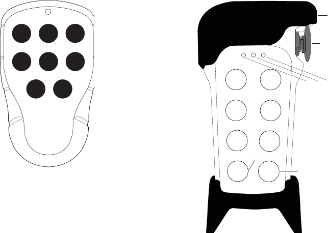
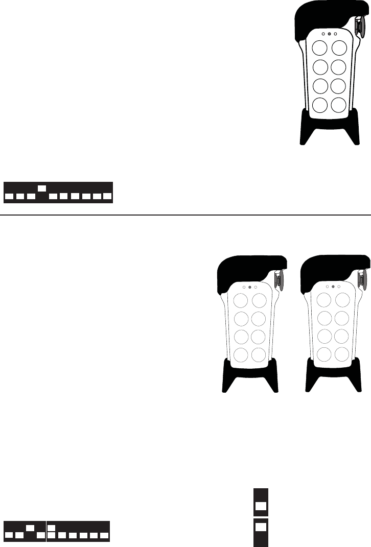
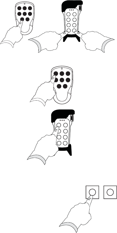
T70TX-08ERB
1. rubber cover
2. STOP button
3. yellow LED1
4. red/ green LED
5. yellow LED 2
6. button 7- START button
7. button 8- START button
7
12
3
7
START
8
START
6
5
4
3.
2.
4.
1.
5.
6.
7.
ON OFF

1. GET STARTED
READ THE INSTRUCTIONS CAREFULLY BEFORE
ASSEMBLING, INSTALLING, PROGRAMMING AND USING
TELE RADIO PRODUCTS.
Tele Radio cannot be held responsible for any damage or other fault caused by a failure
to follow the instructions. Doing so may invalidate the warranty.
IT IS YOUR RESPONSIBILITY TO FIND OUT ABOUT
THE LAWS AND REGULATIONS
THAT APPLY IN YOUR COUNTRY/REGION!
1.2 SAFETY INSTRUCTIONS
This product should only be installed by qualified personnel. s
Switch off the power supply to the receiver before connecting the equipment. s
Turn off the transmitter when not in use. s
Keep a good overview of the work area.s
Use undamaged cables. Make sure that cables do not hang loose. s
Avoid installing the product in areas affected by strong vibrations. s
Only qualified personnel should have access to the transmitter.s
Do not leave the transmitter unsupervised.s
Contact your dealer for repair and maintenance work on the product.s
Retain the instructions for future reference and re-programming of the system. s
If the manual does not cover all your needs, visit our website for FAQ & the latest information:
www.tele-radio.com
1.3 TECHNICAL DATA
THE SYSTEM
OPERATING FREQUENCY: 433.075-434.650 MHz.
CHANNEL: 64 (divided into 4 banks)
CHANNEL SEPARATION: 25 kHz.
RECEIVER
T70RX-09SB 9 relays
T70RX-15SB 15 relays (with expansion board)
WEIGHT: 700 grams (15 relays)
TRANSMITTER T70TX-08ERB
SIZE: 95 x 185 mm. (incl. rubber cover)
WEIGHT: 300 grams (incl. batteries)
TRANSMITTER T70TX-06TTB
SIZE: 113 x 66 x 35 mm.
WEIGHT: 120 grams (incl. batteries)
1.4 RECEIVER POWER SUPPLY
POWER SUPPLY CURRENT CONSUMPTION CURRENT CONSUMPTION
7
ON OFF
12 V DC 30mA 300 mA
24 V AC 12 mA 150 mA
24 V DC 15 mA 200 mA
48 V AC 7 mA 100 mA
(MIN.) (MAX.)
115 V AC 7 mA 50 mA
230 V AC 7 mA 30 mA
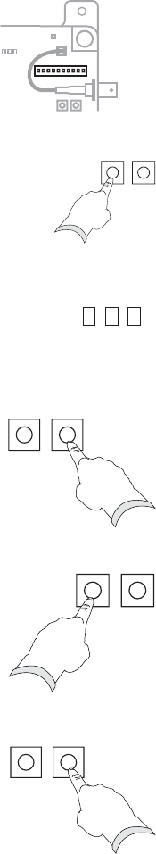
1.5 CHECK THE CONTENTS
Check that you have got the product that you ordered. If anything is missing, please
contact your dealer immediately. The delivery also contains:
3 alkaline batteries for the transmitters
1 connection combs
1 installation and programming instruction manual s
1.6 CONNECT THE RECEIVER
Check that you have connected the power supply to the correct connection s
terminal.
Note that all relays are potential-free, which means that you need to supply voltage if s
you want power out of a relay (e.g. via a connection comb).
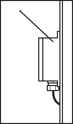
1.7 INSTALL RECEIVER AND ANTENNA
1.7.1 Place the receiver
Well protected from wind, damp and water. s
With cable holders and vent plugs face down to prevent s
water from seeping in (see picture).
If the receiver is to be placed in a a hard-to-reach place, it s
is advisable to complete the settings in the receiver before
mounting it.
1.7.2 Place the antenna
As high above the ground as possible.s
In as free position as possible.s
Well away from metal objects, such as metal girders, high-voltage cables and other s
antennas.
Check that there is a good connection between the antenna and the material on s
which it has been installed, e.g. after repainting of the chassis.
Check that the antenna aerial and any coaxial cables are undamaged.s
Check that the antenna is directed upwards at a 45° angle. s
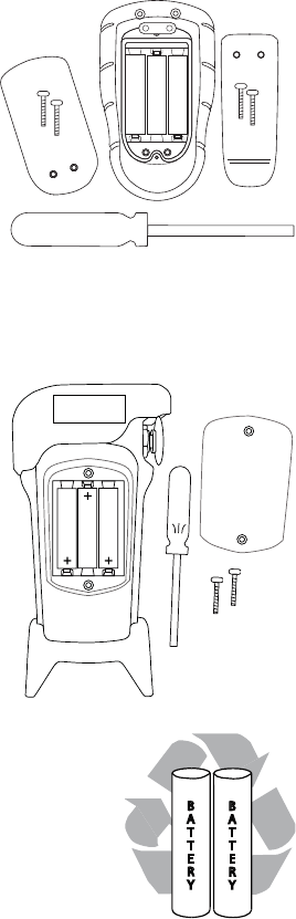
1.8 INSTALL BATTERIES IN THE TRANSMITTER
1.8.1 On the T70TX-06TTB transmitter
Remove the clip.1.
Remove the battery cover.2.
Put the batteries in.3.
Put back the battery cover (2 screws).4.
Put back the clip (2 screws).5.
For optimum performance, use alkaline batteries.
NOTE! If you need to change the frequency bank, we
recommend doing this before putting back the battery cover and clip.
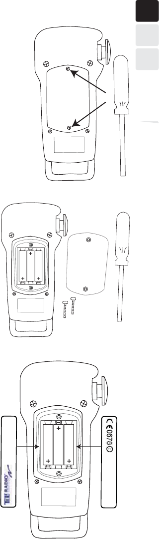
1.8.2 On the T70TX-08ERB transmitter
Remove the battery cover.1.
Put the batteries in. 2.
Put back the battery cover (2 screws).3.
For optimum performance use alkaline batteries.
1.9 RECYCLING OF BATTERIES
Used batteries should always be recycled. Contact your local
authority or dealer for more information on proper recycling of
batteries in your area.
1.10 TRANSMITTER ID CODE
On the T70TX-08ERB transmitter
Write down the transmitter ID code in the Settings document. See picture above for
label position. Label is placed under the rubber cover.
ID code
#
"
5
5
&
3
:
#
"
5
5
&
3
:
2 TRANSMITTER SETTINGS
2.1 Starting/ turning the transmitter off
2.1.1 Starting T70TX-06TTB
1. Press the ON button for at least 1 second.
When the transmitter is active, the transmitter LED flashes red. When transmitting,
the transmitter LED lights red continuously.
2.1.2 Turning off T70TX-06TTB
Press the OFF button.1.
The transmitter LED goes out.
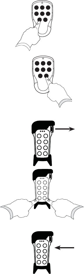
2.1.3 Starting T70TX-08ERB
1. Pull out the STOP button.
2. Press the START buttons 7 and 8 for at least
1 second.
If the transmitter LED is flashing red, the STOP button has not been pulled
out.
When the transmitter is active, the transmitter LED is flashing green.
When the transmitter is transmitting, the transmitter LED lights green
continuously.
NOTE! If the transmitter LED is lighting or flashing red instead of green,
the battery power may be low. Check the batteries.
2.1.4 Turning off T70TX-08ERB
1. Press the STOP button. The transmitter is now turned off.
7
ON
OFF
778
7
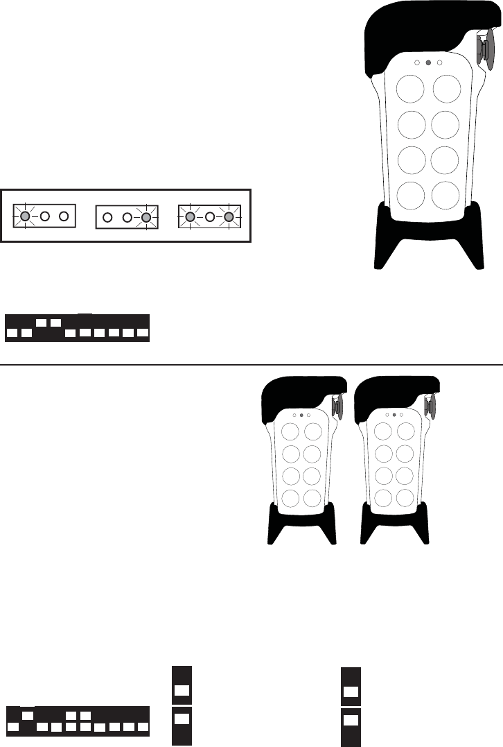
2.2 AUTOMATIC SHUTDOWN SETTINGS
2.2.1 T70TX-06TTB transmitter
The transmitter will turn off after1 minute idle. This cannot be adjusted.
2.2.2 T70TX-08ERB transmitter
Automatic shutdown means that the transmitter will switch itself off, if you do not press
a button for 1 minute (you can adjust this time according to the table below).
The transmitter does not log off from the receiver when it is automatically shut down.
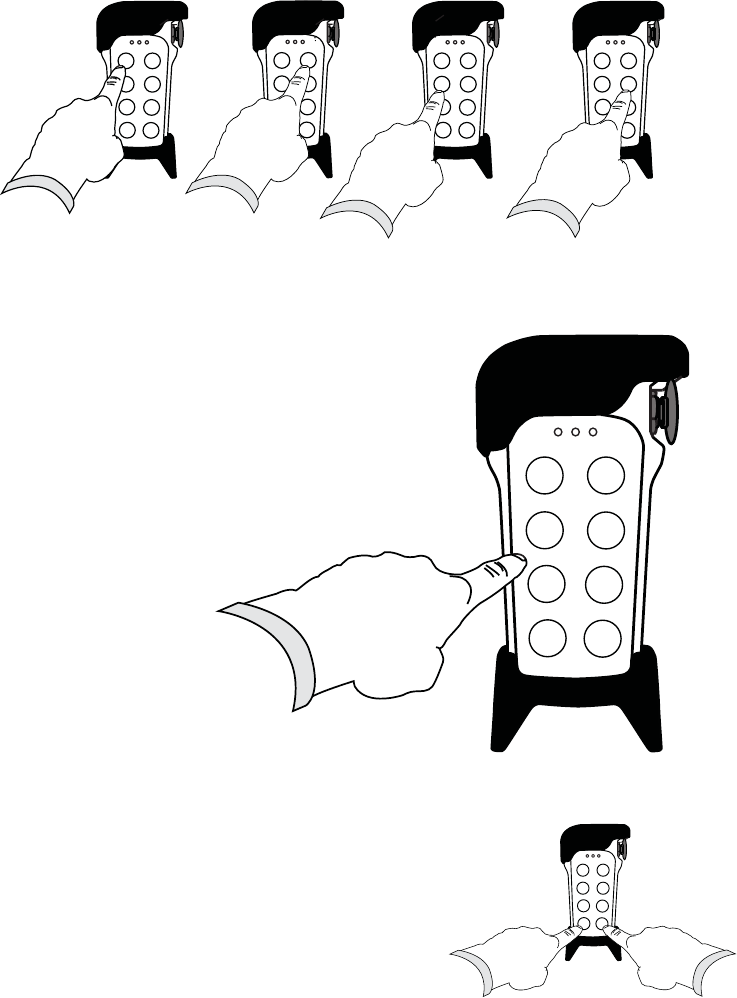
2.2.3 Change Automatic Shutdown time
1. Start the transmitter by pressing the START
buttons 7 and 8
for at least 1 second.
.
2. Keep button 8 pressed. Release button 7.
3. Release button 8.
Within 0.3 seconds: Press button 3.
Yellow transmitter LED 2 lights up and the green transmitter LED
begins to flash.
If you exceed the 0.3 second interval, the transmitter will exit the
programming mode and will
start up instead.
77
8
3
7
1 No automatic shutdown
2 1 minute
3 3 minutes
4 6 minutes
5 12 minutes
OPTION TIME
7
8
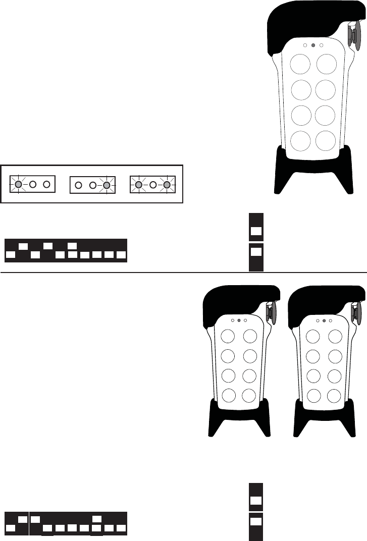
4. Enter the security code 1, 2, 3, 4 (up to 4 seconds between each number).
The
transmitter LED
starts to flash green and yellow
transmitter LED
2 goes out.
5. Enter your choice 1-5:
______________________
1= no automatic shutdown
2= 1 minute
3= 3 minutes
4= 6 minutes
5= 12 minutes
Yellow transmitter LED 1 flashes 3
times when the time setting has been
changed.
6. Make sure to write down the new time for automatic
shutdown in the Settings document.
6.
Re-start the transmitter by pressing
the START
buttons 7 and 8 for at least 1 second.
7
1 2
777
3 4
7
1 min.
0 min.
3 min.
6 min.
12 min.
778
2.3 FREQUENCY SETTINGS
If your product will be used in an area with very little risk of interference from other
radio-controlled equipment, skip this section. If necessary, you can switch the frequency
at a later date. (See the first pages of the manual for frequency table).
2.3.1 Switch frequency bank on T70TX-06TTB
NOTE! IF YOU NEED TO SWITCH FREQUENCY BANK, WE RECOMMEND DOING THIS
BEFORE REPLACING THE BATTERY COVER AND CLIP. MAKE FREQUENCY BANK
SETTINGS BEFORE STORING THE TRANSMITTER IN THE RECEIVER. IF YOU WANT TO
SWITCH FREQUENCY BANK AFTER STORING THE TRANSMITTER IN THE RECEIVER, YOU
WILL HAVE TO ERASE THE TRANSMITTER FROM THE RECEIVER, SWITCH FREQUENCY
BANK AND THEN RE-STORE THE TRANSMITTER IN RECEIVER.
1. Remove the clip and battery cover on the back of the
transmitter using a screw-driver. Remove any batteries
that have been installed. Take off the transmitter’s black
casing.
2. Select frequency bank (see table below) on the two
switches on the circuit board behind the batteries. The
default setting is channel 1 in frequency bank 1.
3. Make sure to write down the new frequency bank in
the Settings document.
SWITCH 1 SWITCH 2 FREQUENCY BANK
OFF OFF 1
ON OFF 2
OFF ON 3
ON ON 4
ON
1
ON
1
ONON
OFFOFF
ON
1
ON
1
ONON
OFFOFF
switch 1
switch 2
2.3.2 Moving up and down within a frequency bank on
T70TX-06TTB
The user can move up and down within a frequency bank while using the transmitter.
This can be useful if there is a major risk of interference within the work area. The default
setting is channel 1 in frequency bank 1.
The transmitter must be on.
1. Press the OFF button and keep it pressed.
2.
Within 3 seconds:
Press ON without releasing OFF.
Transmitter LED flashes for 5 seconds.
3. Release ON and OFF.
4. To move DOWN in frequency, press button 1.
(1 press = 1 step in the table).
To move UP in frequency, press button 2.
(1 press = 1 step in the table).
The transmitter LED flashes 3 times.
The transmitter turns off. The next time you start the transmitter, it will start in the new
frequency.
NOTE! The next time that you activate the receiver by pressing a button on the transmitter,
it can take up to 3 seconds for the receiver to connect to the transmitter.
OFF
ON OFF
1
2
2.3.3 Move more than one step on the T70TX-06TTB
If you want to move several steps in frequency, you will need to restart the transmitter
after every step. In this case you don´t have to wait until the receiver connects to the
transmitter.
If you move all the way to the bottom of the frequency table, the next step will be back to the top. If you move
all the way to the top of the frequency table, the next step will be right at the bottom.
2.4 Switch frequency bank on the T70TX-08ERB
NOTE! MAKE FREQUENCY BANK SETTINGS BEFORE STORING THE TRANSMITTER IN
THE RECEIVER. IF YOU WANT TO SWITCH FREQUENCY BANK AFTER STORING THE
TRANSMITTER IN THE RECEIVER, YOU WILL HAVE TO ERASE THE TRANSMITTER FROM
THE RECEIVER, SWITCH FREQUENCY BANK AND THEN RE-STORE THE TRANSMITTER IN
THE RECEIVER.
1.
Start the transmitter by pressing the START
buttons 7 and 8 for at least 1 second.
2. Keep button 8 pressed. Release button 7.
3.
Release button 8.
Within 0.3 seconds:
Press button 2.
Yellow LED 2 lights up and the green LED flashes.
If you exceed the 0.3 second interval, the transmitter exits programming mode and
starts up.
778
7
8
2
7
4. Enter the security code 1, 2, 3, 4
(up to 4 seconds between each number).
The green LED flashes and yellow LED 2 goes out.
5. Press the 3-digit number for OPTION
(See the first pages of the manual for
frequency table).
Yellow transmitter LED 1 flashes 3 times when the setting
has been made.
6. Make sure to write down the new frequency bank in the Settings document.
7.
Re-start the transmitter by pressing the START buttons
7 and 8 for at least 1 second.
7
1 2
777
3 4
CHANNEL FREQ.BANK 1 OPTION
1 433.075 111
2 433.175 112
3 433.275 113
4 433.375 114
5 433.475 115
778
2.4.1 Settings to move up and down within a frequency
bank on T70TX-08ERB
Decide how to move up and down within a frequency bank. Skip this section if you do
not want to change the default settings.
1. SAVE NEW FREQUENCY (default setting). When a user moves up or down within
a frequency bank, the transmitter saves the new frequency and uses it the next time it is
started up.
2. TEMPORARY MOVE When a user moves up or down within a frequency bank,
the transmitter will not save the new frequency. The new frequency is only used until the
transmitter is restarted.
3. OFF Users are not able to move up or down within a frequency bank.
1.
Start the transmitter by pressing the START buttons 7
and 8 for at least 1 second.
2. Release button 7.
Keep button 8 pressed.
3. Release button 8.
Within 0.3 seconds:
Press button 2.
Yellow transmitter LED 2 lights and the transmitter LED begins to flash green.
If you exceed the 0.3 second interval, the transmitter will exit the programming mode
and starts up.
778
7
8
2
7
4. Enter the security code 4, 6, 3, 5 (up to 4 seconds between each number).
The transmitter LED flashes green. Yellow transmitter LED 2 lights up.
5. Enter your choice:
1. SAVE NEW FREQUENCY
2. TEMPORARY MOVE
3. OFF
The transmitter turns off.
Yellow transmitter LED 2 goes out.
6.
Re-start the transmitter by pressing the START buttons
7 and 8 for at least 1 second.
2.4.2 Move up and down within a frequency bank
on T70TX-08ERB
Allowing users to move up and down within a frequency bank when using the transmitter
can be useful, if there is a major risk of interference within the work area (see previous
section).
1.
Start the transmitter by pressing the START buttons 7 and
8 for at least 1 second.
7
6
7
4
77
5
3
7
1
2
3
778
7
78
2. Release button 7. Keep button 8 pressed.
1a.
Keep button 8 pressed.
Press 1 to move DOWN within
the frequency.
Yellow transmitter LED 1 lights up.
1b.
Keep button 8 pressed.
Press 2 to move UP within the
frequency.
Yellow transmitter LED 2 lights up.
NOTE! If you move all the way to the bottom of the frequency table, the next step will be back to the top. If you
move all the way to the top of the frequency table, the next step will be right at the bottom.
2. Release all buttons.
The frequency setting is now changed. Depending on the settings, this may apply until you turn off the transmitter
or until the frequency is being switched again.
2.4.3 Check the current frequency of the transmitter
on T70TX-08ERB
You can use the transmitter to find out what frequency it is currently set to send within.
1.
Start the transmitter by pressing the START buttons 7
and 8 for at least 1 second.
2. Release button 7.
Keep button 8 pressed.
7
78
78
7
1
8
a.
7
2
8
b.
7
8
3.
Release button 8.
Within 0.3 seconds:
Press button 2.
Yellow transmitter LED 2 lights up and the transmitter LED flashes green.
If you exceed the 0.3 second interval, the transmitter will exit the programming mode and
starts up.
4. Enter the security code 3, 4, 4, 3 (up to 4 seconds between each number).
The green
transmitter LED
starts to flash. Yellow
transmitter LED
2 lights up.
1. FREQUENCY BANK 1-4:
The transmitter LED lights green + yellow transmitter LED 2 flashes 1-4 times depending
on what frequency BANK the transmitter is sending on.
2. FREQUENCY CHANNEL 1-16:
The transmitter LED lights red + yellow transmitter LED 2 flashes 1-16 times depending
on what frequency CHANNEL the transmitter is sending on.
The flashing sequence will be repeated until the transmitter is turned off.
2
7
7
33
7
4
7
3
3
7
4
3 RECEIVER SETTINGS
3.1 FUNCTION SELECTION
You can make several selections to decide how to use your system. Some of the settings
are made on the transmitter, others are made on the receiver. You can see the Function
Selections available for your transmitter in this section. This is followed by the selections
that you can do on the receiver. Read through the following sections carefully before
making the Function Selection choice.
3.1.1 T70TX-06TTB transmitter
This transmitter is designed to control one receiver. The standard setting therefore is
Function Selection 1, which can not be modified. Find out how the system works in the
section called Operating Mode 1.
3.1.2 T70TX-08ERB transmitter
If you want to use your transmitter to control a single receiver, you don´t have to do
anything. The default setting is Function Selection 1, which is for controlling only one
receiver. If you want to control 2 receivers at the same time or one after another, choose
Function Selection 2.
3.1.3 The yellow LEDs on
T70TX-08ERB
When the transmitter button 8 is set on Function
Selection 2, you can control the transmitter’s 2
yellow LEDs by scrolling (according to the yellow
LEDs preset startup mode. How to change the
preset startup mode, see the Set yellow LEDs on
the transmitter at start up section).
3.1.4 Choosing Function Selection 1 or 2 on
T70TX-08ERB
1.
Start the transmitter by pressing the START buttons 7 and 8
for at least 1 second.
73
8/14 9/15
6/12
4/10
7/13
5/11
FUNCT.
SELECT.
12
778
2. Release button 7.
Keep button 8 pressed.
3. Release button 8.
Within 0.3 seconds: Press 1.
Yellow transmitter LED 2 lights up. The transmitter LED flashes green.
4. Enter the security code 1,2,3,4 (up to 4 seconds between the numbers).
The transmitter LED starts flashing green and yellow transmitter LED 2 goes out.
5. Enter your Function Selection choice: 1 or 2.
Yellow transmitter LED 1 flashes 3 times.
6.
Re-start the transmitter by pressing the START buttons
7 and 8 for at least 1 second.
7
8
7
1
7
1
2
7
7
1 2
777
3 4
778
3.2 OPERATING MODE
There are two receiver models available (see pictures in the first pages of the manual):
T70RX-09SB- 9 relayss
T70RX-15SB- 15 relays (with expansion card)s
With the T70TX-08ERB transmitter you can choose functionality for the system by choosing one of the preset
Operating Modes (see overview on next page). You can change the settings using the receiver switch.
STOP button
When the transmitter is active and the STOP-button is pressed, all relays go off.
3.2.1 How the relays function
Relays 4-9 or 4-15 (with expansion card) are function relays. Relay 1-3 work as described in the next section:
RELAY 1
Activates when the transmitter is turned on.s
Turns off when transmitter buttons 1-7 have not been pressed in the last 6 minutes. s
Does not turn off until the relays that have a latching function have been restored to the OFF position. s
RELAY 2
Always activates when buttons 1-6 are pressed on the transmitter. s
The relay does not turn off until the relays that have a latching function have been restored to
the OFF position (does not apply to relay 3). NOTE! Not in Operating Mode 7.
RELAY 3
Activates when button 7 is pressed on the transmitter. NOTE! Not in Operating Mode 7. s
3.2.2 LOGOUT function
Not available on the T70TX-06TTB transmitter. LOGOUT is activated in all Operating Modes for the
T70TX-08ERB transmitter. (See LOGOUT transmitters section).
3.2.3 Two-step buttons
When two numbers are shown on the same button (see picture), the first indicates the
relay controlled when the button is pressed in halfway and the other indicates the relay
controlled when the same button is fully pressed in.
3.2.4 Time delay between button steps
In some Operating Modes you can program a transmitter button time delay of 0.5
seconds. The delay is between the upper and lower steps of a button. Set switch 6 to ON position. Applies to
Operating Modes 3, 4, 5, 6 and 8.
7
3
11/12 12/13
8/10
4/5
9/10
6/7
FUNCT.
SELECT.
2
OPERATING MODE
RELAYS RECEIVERS TWO-
BUTTONS
INTER-
LOCKING
LATCHING
programmable programmable
programmable
programmable
automatic
automatic
automatic
automatic
automatic
automatic
automatic
automatic
automatic
not possible
not possiblenot possible
OP.
MODE
2
OP.
MODE
1
OP.
MODE
3
OP.
MODE
4
OP.
MODE
5
OP.
MODE
6
OP.
MODE
7
OP.
MODE
8
ON OFF
7
1-2
1-2
1-2
1-2
1-2
1-2
2
2
2
9 or 15
No
No
Ye s
Ye s
Ye s
Ye s
Ye s
Ye s
9 or 15
15
15
15
15
15
9
1-3
1-3
1-3
1-3
1-3
1-3
1-3
_
_
_
_
_
_
_
_
Receiver
switch
OFF
4
579
3
68
OFF
10
11 13 15
3
12 14
OFF
ON
OFF
ON
OFF
ON
OFF
ON
OFF
ON
OFF
ON
OFF
ON
OFF
ON
OFF
ON
OFF
ON
1 2 3 4 5 6 7 8 9 10
RECEIVER SWITCH
3.3 SELECT OPERATING MODE
SELECT OPERATING MODE BEFORE STORING THE TRANSMITTER!
1. Open the receiver (4 screws).
2. Enter the settings on the receiver switch in accordance with the picture shown for
each Operating Mode. In some Operating Modes you can decide
whether to put the switch in ON or OFF position, depending on
what functionality you want for the receiver. A receiver switch that
is possible to change is shown in both ON and OFF positions on
the picture. The functions available by switching it are shown next
to the receiver switch picture.
3.3.1Switch Operating Mode after storing a transmitter
If you want to switch Operating Mode after storing one or more transmitters, you must
erase all previous settings as described below:
1. Open the receiver (4 screws).
2. Make a Master Reset (see Master Reset section), which deletes all settings (interlocking
and latching that are not automatic, as well as storing a transmitter) that you have made
on the receiver. Choose Function Selection 1 or 2, choose Operating Mode and store
the transmitter(s) again.
3.3.2 OPERATING MODE 1
TRANSMITTER: T70TX-06TTB
RECEIVERS: 1 receiver with
9/15 relays
NUMBER OF TRANSMITTERS: 1-2
LATCHING: Available on relays 4-15.
INTERLOCKING: Available on relays 4/5,
6/7, 8/9, 10/11,
12/13 and 14/15.
TRANSMITTER 1 TRANSMITTER 2
activates relays 4-9 activates relays 10-15
3.3.3 Operating Mode 2
TRANSMITTER: T70TX-08ERB
RECEIVERS: 1-2 receiver(s) with 9/ 15 relays
NUMBER OF TRANSMITTERS: 1-3
LATCHING: Available on relays 4-15
INTERLOCKING: Available on relays 4/5, 6/7, 8/9, 10/11, 12/13 och 14/15.
FUNCT. SELECT 1: Yes. Transmitter button 8 no function.
FUNCT. SELECT 2: Yes. Yes. Select Func. Select. 2 on the transmitter.
Transmitter button 8 controls 2 receivers via the
yellow transmitter LEDs. How the LEDs function
depend on how the transmitters are stored (see
Storing transmitters section).
3.3.4 Operating Mode 3
TRANSMITTER: T70TX-08ERB
RECEIVERS: 1-2 receiver(s) with 15
relays
NUMBER OF TRANSMITTERS: 1-3
LATCHING: Available on relay14
INTERLOCKING: Automatic on relays 4/5/6,
7/8/9 and 10/11/12
MODE-SPECIFIKT: Relay 13 is not used
FUNCT. SELECT 1: Yes. Switch 5 in OFF
position: Transmitter
button 8 activates relays
14 and 15 (see picture).
FUNCT. SELECT 2: Yes. Select Func. Select. 2
on the transmitter.
Transmitter button 8
controls 2 receivers via
the yellow transmitter LEDs. How the LEDs function, depend on how the
transmitters are stored (see Storing transmitters section).
73
8/14 9/15
6/12
4/10
7/13
5/11
FUNCT.
SELECT.
2
OFF
ON
OFF
ON
OFF
ON
OFF
ON
OFF
ON
OFF
ON
OFF
ON
OFF
ON
OFF
ON
OFF
ON
1 2 3 4 5 6 7 8 9 10
RECEIVER SWITCH
73
10/12 11/12
14
15
7/9
4/6
8/9
5/6
73
10/12 11/12
7/9
4/6
8/9
5/6
FUNC.SELECT. 2 FUNC.SELECT. 1
FUNCT.
SELECT.
2
OFF
ON
OFF
ON
OFF
ON
OFF
ON
OFF
ON
OFF
ON
OFF
ON
OFF
ON
OFF
ON
OFF
ON
1 2 3 4 5 6 7 8 9 10
RECEIVER SWITCH
OFF
ON
RECEIVER SWITCH 5
Relay 14: latching on
transmitter button 8.
Relay 15: momentary on
transmitter button 8.
No function on
relay 14 och 15.
3.3.5 Operating Mode 4
TRANSMITTER: T70TX-08ERB
RECEIVERS: 1 receiver with 15 relays
NUMBER OF TRANSMITTERS: 1-3
LATCHING: Available on relays 14 and 15
INTERLOCKING: Automatic on relays 4/5/6, 7/8/9 and 10/11/12
MODE-SPECIFIC: Relay 13 is not used
FUNCT. SELECT 1: Not possible
FUNCT. SELECT 2: Yes. Func. Select. 2 must be selected on the
transmitter.
TRANSMITTER’S YELLOW LEDS
activates relay 14 relay 15 relays 14+15
3.3.6 Operating Mode 5
TRANSMITTER: T70TX-08ERB
RECEIVERS: 1-2 receiver(s) with
15 relays
NUMBER OF TRANSMITTERS: 1-3
LATCHING: Available on relay
14
INTERLOCKING: Automatic on
relays 4/5/6/7,
8/9/10 and
11/12/13
FUNCT. SELECT 1: Yes. Switch 5= OFF: Transmitter button 8 activates relays 14 and 15 (see
picture).
FUNCT. SELECT 2: Yes. Select Func. Select. 2 on the transmitter. Transmitter button 8 controls 2
receivers via the yellow transmitter LEDs. How the LEDs function, depend on
how the transmitters are stored (see Storing transmitters section).
73
10/12 11/12
FUNCT.
SELECT.
2
7/9
4/6
8/9
5/6
OFF
ON
OFF
ON
OFF
ON
OFF
ON
OFF
ON
OFF
ON
OFF
ON
OFF
ON
OFF
ON
OFF
ON
1 2 3 4 5 6 7 8 9 10
RECEIVER SWITCH
LED 1 LED 2 LED 1 & 2
73
11/13 12/13
8/10
4/5
9/10
6/7
14
15
73
11/13 12/13
8/10
4/5
9/10
6/7
FUNCT.
SELECT.
2
FUNC.SELECT. 1
FUNC.SELECT. 2
OFF
ON
OFF
ON
OFF
ON
OFF
ON
OFF
ON
OFF
ON
OFF
ON
OFF
ON
OFF
ON
OFF
ON
1 2 3 4 5 6 7 8 9 10
RECEIVER SWITCH
OFF
ON
RECEIVER SWITCH 6
No delay between high-
and lowspeed functions.
A delay of 0.5 seconds
between high and
lowspeed functions.
OFF
ON
RECEIVER SWITCH 5
Relay 14: latching on
transmitter button 8.
Relay 15: momentary on
transmitter button 8.
No function on
relay 14 och 15.
3.3.7 Operating Mode 6
TRANSMITTER: T70TX-08ERB
RECEIVERS: 1 receiver with 15 relays
NUMBER OF TRANSMITTERS: 1-3
LATCHING: Available on relays 14 and 15
INTERLOCKING: Automatic on relays 4/5/6/7, 8/9/10 and
11/12/13
FUNCT. SELECT 1: Not possible
FUNCT. SELECT 2: Yes. Func. Select. 2 must be selected
on the transmitter. Transmitter
button 8 controls the receiver via the yellow
transmitter LEDs. How the LEDs
function depend on how the transmitters are
stored (see Storing transmitters section).
TRANSMITTER’S YELLOW LEDS
activates relay 14 relay 15 relays 14+15
3.3.8 Operating Mode 7
TRANSMITTER: T70TX-08ERB
RECEIVERS: 1 receiver with 9 relays.
NUMBER OF TRANSMITTERS: 1-3
LATCHING: Not possible
INTERLOCKING: Not possible
FUNCT. SELECT 1: Yes. Func. Select. 1
must be selected on the
transmitter.
FUNCT. SELECT 2: Not possible
LED 1 LED 2 LED 1 & 2
7
3
11/12 12/13
8/10
4/5
9/10
6/7
FUNCT.
SELECT.
2
OFF
ON
OFF
ON
OFF
ON
OFF
ON
OFF
ON
OFF
ON
OFF
ON
OFF
ON
OFF
ON
OFF
ON
1 2 3 4 5 6 7 8 9 10
RECEIVER SWITCH
OFF
ON
OFF
ON
OFF
ON
OFF
ON
OFF
ON
OFF
ON
OFF
ON
OFF
ON
OFF
ON
OFF
ON
1 2 3 4 5 6 7 8 9 10
RECEIVER SWITCH
789
67
4
2
5
3
79
78
5
3
6
4
Receiver switch 8=OFF Receiver switch 8=ON
OFF
RECEIVER SWITCH 8
Relay 1 and 2: STOP function
for 6 min. or until pressing
the STOP button.
Relay 1: STOP function for
6 min. or until pressing the
STOP button.
ON
OFF
ON
RECEIVER SWITCH 6
No delay between high-
and lowspeed functions.
A delay of 0.5 seconds
between high and
lowspeed functions.
3.3.9 Operating Mode 8
TRANSMITTER: T70TX-08ERB
RECEIVERS: 1 receiver with 15 relays
NUMBER OF TRANSMITTERS: 1-3
LATCHING: Not possible
INTERLOCKING: Available on relays 4/5/6, 7/8/9, 10/11/12 and 13/14/15
FUNCT. SELECT 1: Not possible
FUNCT. SELECT 2: Yes. Func. Select. 2. must be selected on the transmitter. Transmitter button 8
controls the receiver via the yellow transmitter LEDs.
7
3
10/12 11/12
7/9
4+13/
6+15
8/9
5+14/
6+15
7
3
10/12 11/12
7/9
4/6
8/9
5/6
7
3
10/12 11/12
7/9
13/15
8/9
14/15
FUNCT.
SELECT.
2
FUNCT.
SELECT.
2
FUNCT.
SELECT.
2
LED 1 LED 2
OFF
ON
OFF
ON
OFF
ON
OFF
ON
OFF
ON
OFF
ON
OFF
ON
OFF
ON
OFF
ON
OFF
ON
1 2 3 4 5 6 7 8 9 10
RECEIVER SWITCH
LED 1 & 2
OFF
ON
RECEIVER SWITCH 6
No delay between high-
and lowspeed functions.
A delay of 0.5 seconds
between high and
lowspeed functions.
3.4 CHANGE OF LED THAT LIGHTS UP DURING STARTUP
3.4.1 On the T70TX-06TTB transmitter
The transmitter does not have this option.
3.4.2 On the T70TX-08ERB transmitter
Applies to T70TX-08ERB with Function Selection 2. You can select how the yellow LEDs
on the transmitter will light up when you start the transmitter. The default setting is for
yellow LED 1 to light up when you start the transmitter. If you want to keep the default
setting, skip this section.
1. No yellow LED lights up at start
2. Yellow LED 1 lights up at start
3. Yellow LED 2 lights up at start
4. Yellow LEDs 1 + 2 light up at start
1.
Start the transmitter by pressing the START buttons 7
and 8 for at least 1 second.
2. Release button 7.
Keep button 8 pressed.
3. Release button 8.
Within 0.3 seconds: Press 1.
Yellow LED 2 lights up. The LED starts to flash green.
7
7
8
7
8
7
1

4. Enter the security code 7, 4, 8, 3 (up to 4 seconds between the numbers).
The green LED starts to flash and yellow LED 2 goes out.
5. Enter your choice:
1. No yellow LED lights up
2. Yellow LED 1 lights up
3. Yellow LED 2 lights up
4. Yellow LEDs 1 + 2 light up
Yellow LED 1 flashes 3 times.
6. Re-start the transmitter by pressing the START buttons
7 and 8.
3.5 POWER SAVING FOR YELLOW TRANSMITTER LEDS
3.5.1 On the T70TX-06TTB transmitter
The transmitter does not have this option.
3.5.2 On the T70TX-08ERB transmitter
Applies to T70TX-08ERB with Function Selection 2.
When the transmitter is in Standby
mode (i.e. not transmitting) default setting is that the selected yellow LEDs are
continuously lit. You can make the LEDs flash to increase the battery life by changing the
settings. If you want to keep the default setting, skip this section.
1. The selected Yellow LEDs are continuously lit
2. Selected LEDs flash
7
4
77 77
3
8
7
1
34
2
7
7
8
1.
Start the transmitter by pressing the START buttons 7
and 8 for at least 1 second.
2. Release button 7.
Keep button 8 pressed.
3. Release button 8.
Within 0.3 seconds: Press 1.
Yellow LED 2 lights up. The LED starts to flash green.
4. Enter the security code 7, 5, 4, 5 (up to 4 seconds
between the numbers).
The green LED starts to flash and yellow LED 2 goes out.
5. Enter your choice (1 or 2).
Yellow LED 1 flashes 3 times.
7
7
8
7
8
7
1
7
5
77 77
4
5
7
1
2
7
6. Re-start the transmitter by pressing the START buttons
7 and 8 for at least 1 second.
3.6 LATCHING RELAY FUNCTION
In some Operating Modes you can assign a latching function
to certain relays (see description of Operating Modes). Latching
means that the relay is activated every time a button is pressed,
but remains active until the button is pressed again. You can
set this on the receiver using the FUNCTION button and the
SELECT button.
1. Use the FUNCTION button to switch between the 3 function LEDs:
the red CODE STORING LED1.
the yellow LATCH LED2.
the green INTERLOCKING LED3.
2. Stop at the yellow LATCH LED and select it by using the
SELECT button. The yellow LATCH LED will go out. The red
LED above relay 4 will light up.
3. Use the SELECT button to select the relay that you want
to assign a latching function. Press the FUNCTION button to
light up the yellow LATCH LED. If the yellow LATCH LED is
already lit and the red LED above a relay lights up, this relay has
already been assigned a latching function. To remove the latching
function from a relay, press the FUNCTION button once, so
that the yellow LATCH LED goes out.
4. To assign latching to more relays, use the SELECT button to
select the next relay that you want to assign a latching function
to. The receiver will exit the code storing mode after 10
seconds idling.
7
7
8
Receiver
switch
2 3 1
FS
FS
FS
3.7 INTERLOCKING RELAY FUNCTION
In some Operating Modes you can assign an interlocking
function to certain relays (see description of Operating
Modes). Interlocking means that you can prevent selected
relays from activating at the same time, even if the buttons
are pressed at the same time, e.g. moving up and down. If two
relays are interlocked, nothing will happen if the user presses
both buttons at the same time. You can set this on the receiver
using the FUNCTION button and the SELECT button.
1. Use the FUNCTION button to switch between the 3 function LEDs:
the red CODE STORING LED1.
the yellow LATCH LED2.
the green INTERLOCKING LED3.
2. Stop at the green INTERLOCKING LED and select it by using the
SELECT button. The green INTERLOCKING LED goes out. The red
LEDs above relays 4 and 5 will light up.
3. Press the FUNCTION button to light up the green
INTERLOCKING LED. If the green INTERLOCKING LED is already
lit and the red LEDs above a relay pair light up, this relay pair has
already been assigned an interlocking function. To remove the
interlocking function from a relay pair, press the FUNCTION button
once, so that the green INTERLOCKING LED goes out.
4. To assign interlocking to more relay pairs, use the SELECT button
to select the next relay pair that you want to assign an interlocking
function. The receiver will exit code storing mode after 10 seconds
idling.
Receiver
switch
2 3 1
FS
FS
FS
FS
3.8 STORE THE TRANSMITTER IN THE RECEIVER
NOTE! Do not store the transmitter in the receiver until you have selected
Operating Mode.
Depending on receiver model, you can store 1-3 transmitters. If the maximum number
of transmitters has already been stored, all transmitters must be erased before you can
store the transmitters that you want. NOTE! If several transmitters are used with one
receiver, they must all use the same frequency bank.
1. Start the transmitter that you want to
store.
2. Press any transmitter button, e.g. button 1,
and keep it pressed.
2. Press the receiver’s FUNCTION button for more than
0.3 seconds.
The red CODE STORING LED on the receiver will light up.
ON
77
8
7
1
1
FS
3. Press the receiver’s SELECT button.
All red relay LEDs will light up.
The receiver will now start to search for and connect to the transmitter.
4. When the transmitter has been stored, the red relay
LEDs on the receiver will flash 3 times.
5. Release button 1.
3.9 Erase transmitters
1. Press the receiver’s FUNCTION button for more than
0.3 seconds.
The red CODE STORING LED on the receiver lights up.
3. Press the SELECT button.
All the red relay LEDs lights up.
Hold down the SELECT button for more than 4 seconds.
4. All the red relay LEDs on the receiver will go out when all
transmitters have been deleted.
3.10 MASTER RESET OF THE RECEIVER SETTINGS
If you need to delete the settings you have made on the receiver (storing of transmitters
as well as interlocking and latching relay functions), you can perform a Master Reset. The
Operating Mode will not be deleted. To switch Operating Mode, change the position of
receiver switch 1-4.
1. Press both the FUNCTION button and the SELECT
button.
All three function LEDs (the red CODE STORING LED, the yellow LATCH LED and
the green INTERLOCKING LED) light up.
FS
FS
FS
FS
2. Hold down the FUNCTION button and the SELECT button for more than 10 seconds.
After 10 seconds, the receiver’s memory has been erased.
3.11 LOGOUT TRANSMITTERS
3.11.1 On the T70TX-06TTB transmit-
ter
There is no LOGOUT function on this transmitter.
3.11.2 On the T70TX-08ERB transmit-
ter
If you want to use more than one stored transmitter with your
receiver, you must LOGOUT the transmitter that you used last.
LOGOUT 1
There are 3 ways to LOGOUT a transmitter:
1. Start the transmitter that you want to LOGOUT.
2. Press the transmitter’s STOP button.
3. When the transmitter’s red LED begins to flash, press button
7 within 2 seconds.
Yellow transmitter LED 1 starts to flash.
4. The transmitter is now logged out. It will turn off when the
yellow transmitter LED stops flashing. You can now log on to
the receiver using another already stored transmitter.
FS
7
77
LOGOUT 2- only if button 7 is not used for a high-risk
function
1. Start the transmitter you want to log out.
2. Press button 7.
3. Press the STOP button without releasing button 7.
The red transmitter LED lights up for 1 second. Yellow transmitter LED
1 flashes.
4. The transmitter is now logged out and turns
itself off. You can now log on to the receiver using
another already stored transmitter.
LOGOUT 3- if transmitter can´t be used
1. Press the SELECT button for at least 4 seconds. The green
LOG ON/OFF LED on the receiver will go out.
2. You can now log on to the receiver using another stored
transmitter.
3.12 REPLACE TRANSMITTERS
3.12.1 On the T70TX-06TTB transmitter
There is no replacing function on this transmitter.
77
77
FS
EN
ES
FR
40
REPLACE TRANSMITTERS
On the TX1-C transmitter
There is no replacing function on this transmitter.
On the TX2 transmitter
To replace a lost or broken transmitter with a new, without having to use the receiver.
Simply use the new transmitter for all button operations.
NOTE! The new transmitter must use the same frequency bank as the
transmitter that is being replaced.
1. Start the new transmitter.
2. Press the new transmitter´s STOP button.
3. The transmitter LED lights red.
Within 2 seconds: Press button 5 and 6.
Yellow transmitter LED 1 lights.
4. Enter the product ID code for the transmitter that you
want to erase (found under the rubber cover).
The transmitter LED lights red. Yellow transmitter LED 2 flashes.
The new transmitter can now be used with the receiver.
778
ID code
7
7
56
EN
ES
FR
41
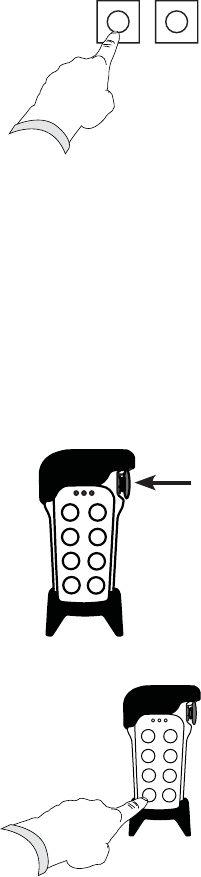
THE REMOVABLE RUBBER COVER
On the TX2 transmitter
The TX2 transmitter comes with a removable rubber cover that helps prevent the
transmitter from bumps, dirt and dust. The rubber cover can be easily removed and
wiped off.
THE RUBBER COVER MUST BE REMOVED TO:
1. Reveal the FCC statements label (see picture below).
2. Reveal the ID code for the product (not the FCC ID code).
How to remove the rubber cover
1. Loosen the rubber cover, starting at the top.
2. Lift the transmitter up out of the
rubber cover.
How to replace the rubber cover
1. Place the transmitter in the rubber cover, starting at the bottom.
2. Put the rubber cover back on the transmitter.
This device complies with part 15 of the
FCC Rules. Operation is subject to the fol-
lowing two conditions: (1) This device
may not cause harmful
interference, and
(2) this device must accept any
interfe -
ence received, including interference
that may cause undesired operation.
FCC statements
EN
ES
FR
42
LOCATE THE IC AND FCC LABELS
1. Reveal the product information label
(see picture).
2. Reveal the FCC and IC label (see picture
below).
On the TX1-C transmitter
1. Remove the clip (2 screws).
2. Remove the battery lid (2 screws) and
the batteries.
3. The FCC and IC labels are placed on
the inside of the battery compartment.
The FCC label is placed on the right side.
The IC label is placed on the left side.
IC: 4807A-T70TX0XXTB
Model No. T70TX
-06TTB
FCC ID: ONFT70TX-0XXTB
EN
ES
FR
43
On the TX2 transmitter
1. Remove the battery lid (2 screws)
and the batteries.
.
3. The FCC and IC labels are placed on the inside of the
battery compartment.
The FCC label is placed on the right side. The IC label is
placed on the left side.
IC: 4807A-T70TX08ERB
Model No. T70TX
-08ERB
FCC ID: ONFT70TX-08ERB
EN
ES
FR
44
IC AND FCC LABELLING
TX1-C TX2
FCC STATEMENTS
THIS DEVICE COMPLIES WITH PART 15 OF THE
FCC RULES. OPERATION IS SUBJECT TO THE
FOLLOWING TWO CONDITIONS:
1. THIS DEVICE MAY NOT CAUSE HARMFUL
INTERFERENCE
2. THIS DEVICE MUST ACCEPT ANY
INTERFERENCE THAT MAY CAUSE UNDESIRED
OPERATION.
NOTE: THE MANUFACTURER IS NOT
RESPONSIBLE FOR ANY RADIO OR TV
INTERFERENCE CAUSED BY UNAUTHORIZED
MODIFICATIONS TO THIS EQIPMENT. SUCH
MODIFICATIONS COULD VOID THE USER´S
AUTHORITY TO OPERATE THE EQUIPMENT.
DIRECTIVES AND
STANDARDS
This product complies with current European
directives and standards. “Declaration of Conformity”
can be downloaded from: www.tele-radio.com.
GUARANTEE
Tele Radio’s products are covered by a guarantee
against material, construction or manufacturing faults.
During the guarantee period Tele Radio may replace
the product or faulty parts with new ones. Work
under warranty must be carried out by Tele Radio
or by an authorized service centre specified by Tele
Radio.
The following faults are not covered by the warranty:
s Faults resulting from normal wear and tear.
s Parts of a consumable nature.
s Products that have been subject to
unauthorized modifications.
s Faults resulting from incorrect installation or
use.
s Damp or water damage.
SERVICING & REPAIRS
Make sure that repairs and maintenance are only
carried out by qualified personnel. Only use spare
parts from Tele Radio.
Contact your dealer if you want to make a complaint
about a product or require other service. Always
have the following details to hand when you contact
a dealer about a complaint or service issue: Name of
the system, model and a description of the problem. If
you need to return a product, the invoice number and
delivery date should be included.
OPERATING
GUIDELINES
s Keep the product in a dry, clean place.
s Make sure that contacts and antennas are kept
clean.
s Wipe off dust using a slightly damp, clean cloth.
s Never use cleaning solutions or high-pressure
water.
s
IC label:
IC: 4807A-T70TX08ERB
FCC label:
FCC ID: ONFT70TX-08ERB
IC label:
IC: 4807A-T70TX0XXTB
FCC label:
FCC ID: ONFT70TX-0XXTB
0678

TELE RADIO SVERIGE
Sweden
Tel. +46 (0)31-724 98 00
e-mail: sverige@tele-radio.com
TELE RADIO LTD
England
Tel. +44 (0) 1625 509125
e-mail: sales@teleradiouk.com
TELE RADIO OÜ
Estonia
Tel. +372 44 511 55
e-mail: m.jyrissoo@tele-radio.com
TELE RADIO LLC
North America & Latin America
Tel. +1 (305) 459 0763
e-mail: america@tele-radio.com
TELE RADIO AB
Sweden, Main office
Tel. +46 (0)31-748 54 60
e-mail: info@tele-radio.com
www.tele-radio.com
TELE RADIO ASIA
China
Tel. +86-(0)592-3111168
e-mail: b.sun@tele-radio.cn
TELE RADIO AS
Norway
Tel. +47-6933 4900
e-mail: norway@tele-radio.com
TELE RADIO TURKEY
Turkey
Tel. +90-532 292 4448
e-mail: c.mevlevioglu@tele-radio.com
TELE RADIO GmbH
Germany
Tel. +49 (0)94 51-944 8 550
e-mail: kontakt@tele-radio-gmbh.de
TELE RADIO BV
Benelux
Tel. +31-(0)70-419 41 20
e-mail: info@teleradio.nl