Tele Radio T860TX-12 902-928MHz FREQUENCY HOPPING TRANSMITTER User Manual IM 860 010 A2 indb
Tele Radio AB 902-928MHz FREQUENCY HOPPING TRANSMITTER IM 860 010 A2 indb
users manual

1
Tele Radio 860
Manual
Rev. IM-860-010-A3

2
CONTENTS
3-4
5-32
33-60
61-88
89-116
117-144
145-173
174-202
203-232
. . . . . . . . . . . . . . . 860TX/860RX
. . . . . . . . . . . . . . . Dansk
. . . . . . . . . . . . . . . Norsk
. . . . . . . . . . . . . . . Svensk
. . . . . . . . . . . . . . . Nederlands
. . . . . . . . . . . . . . . Español
. . . . . . . . . . . . . . . Français
. . . . . . . . . . . . . . . Deutsch
. . . . . . . . . . . . . . . English
.
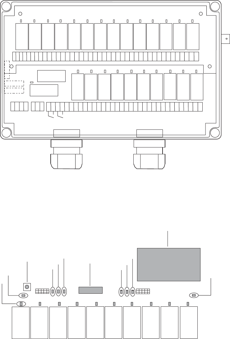
860RX
1= Red LED 1
2= Yellow LED 2
3= Reset button
4= Green LED 4
5= Red LED 5
6= Yellow LED 6
7= Function selector switch
8= Green LED 8
9= Red LED 9
10= Yellow LED 10
11= Radio module
12= Green LED 12
456
89
10
7
2
3
12
11
1
* Fuse S1, S2 and S3 ceramic slow.
S1 200 mA
S2 300-315 mA
S3 500 mA
8 9 10 11 12 13 14 15 16 17 18 19 20 21 22 23 24 25 26 27 28 29 30 31 32 33 34 35 36 37 38 39 40 41
SR1 SR2
54 55 56 57 58 59 60 61 62 63 64 65 66
42434445 46 47 48 49 50 5251 53 67 68 757472717069 73 818079787776 82 83
SR2
SR1
* S3
* S2
*
S1
1 2 3 4 5 6 7
230VAC
115VAC
48 VAC
0 V
24V AC/DC
12V DC
0 V
Start
4
21
3
5
7
90
3
12
6
8
2
1
X1X
X
2
Start
860TX-10
860TX-12
1
23
12
X
Start
Start
2
4
6
8
0
1
3
5
7
9
4
12
3
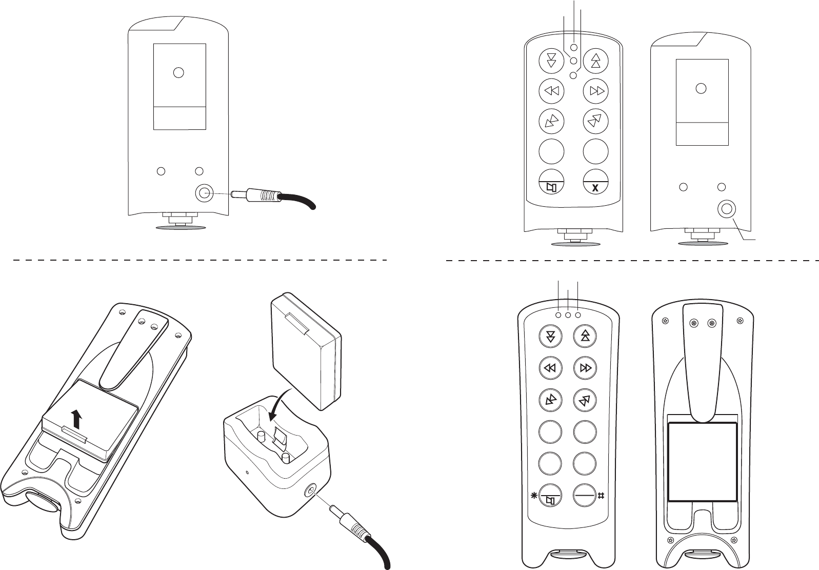
1 = Yellow LED 1
2 = Yellow LED 2
3 = Red/ Green LED 3
1 = Yellow LED 1
2 = Yellow LED 2
3 = Red/ Green LED 3
4 = Charge connector
Charging the 860TX-12
Charging the 860TX-10
12-35V DC
12-35V DC

203
ESFRDEEN DKNOSENL
IMPORTANT!
In order to get the best out of your system it is important you take the time to read through
the manual before you start to install/program your equipment.
ENSURE THAT:
• Qualified personnel receive a review of the system’s functions before it is used.
• Only qualified personnel have access to the transmitter.
• The transmitter is not left unsupervised.
• The transmitter is switched off when not in use.
• The operator always has a complete view of the equipment when radio controlled.
TO GET STARTED:
• Start by entering the system’s serial number on the Settings form for the receiver and transmitter settings.
Enter the other data on the form as you program the system.
• It is an advantage to program as many of the required functions as possible before the receiver is installed, if
the receiver is to be placed high up or in any other inaccessible position.
• Check that the supply voltage to the receiver is correct.
CONTENTS /ENGLISH
Important! .....................................................................................................................................................................................................203
System Functions ........................................................................................................................................................................................204
Transmitter ...................................................................................................................................................................................................205
Receiver 860RX ..........................................................................................................................................................................................206
Installing the receiver and the receiver antenna ...............................................................................................................................207
Co-programming the transmitter and receiver ................................................................................................................................208
Erasing all the transmitters in the receiver .........................................................................................................................................208
Replace a transmitter in the receiver ...................................................................................................................................................208
Lock/unlock a receiver ..............................................................................................................................................................................209
Radio module mode ..................................................................................................................................................................................210
Changing the frequency ............................................................................................................................................................................211
Automatic Shut-off .....................................................................................................................................................................................213
Pin code function ........................................................................................................................................................................................214
Erasing all pin-codes ..................................................................................................................................................................................215
Time delay between pushbuttons .........................................................................................................................................................215
Function selector ........................................................................................................................................................................................216
The transmitter’s function selections and led indications .............................................................................................................. 218
Yellow LED/start-up ..................................................................................................................................................................................219
The receiver’s function selection/relay functions ..............................................................................................................................220
Momentary or latched relay functions ................................................................................................................................................226
Interlocks ...................................................................................................................................................................................................... 226
Stop function selector ...............................................................................................................................................................................228
Trouble shooting .........................................................................................................................................................................................229
Disposal .........................................................................................................................................................................................................229
Settings form: receiver and transmitter ...............................................................................................................................................230

204
EN DE FR ES NL SE NO DK
SYSTEM FUNCTIONS
Frequency
System 860 uses 69 different frequencies, which makes it possible to use several transmitters and receivers
within the same coverage area.
Battery status
The transmitter has an integrated battery indicator which shows when only approx. 10% of the battery capacity
remains.
Automatic shut-off
The transmitter has an automatic shut-off function built-in to conserve battery power. The available selections
for automatic shut-off are: after 2, 6 or 12 minutes, or no automatic shut-off.
Pin code
Up to 10 individual/personal PIN codes can be programmed on each transmitter.
Time delay between pushbuttons
Time delays can be programmed between pushbuttons and between first and second step in the pushbutton.
Logging off/on
The receiver can be programmed to accept up to three different transmitters, where each transmitter has its
own unique code. For reasons of safety only one transmitter at a time can be logged on. The current transmit-
ter must first be logged off before another transmitter can be logged on.
Function selection
The system offers the possibility of programming different combinations of relay functions.
Momentary or latched relay functions
Each function relay can be programmed for momentary or latched relay operations.
Interlocking
Using this function it is possible to interlock/prioritise a relay function/button before another. If interlocking has
been programmed and two buttons on the transmitter are pressed simultaneously, one of the buttons is given
priority/interlocked over the other, which means, for example, up and down movements can not be operated at
the same time.
Safety relay
The receiver is supplied with two safety relays, which are continuously monitored.
Integrated safety function when the transmitter starts: 0-position monitoring
If any button is inadvertently pressed when the transmitter is starting, the transmitter will not start. This is
indicated by a red LED. So-called 0-position monitoring.
205
ESFRDEEN DKNOSENL
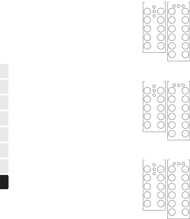
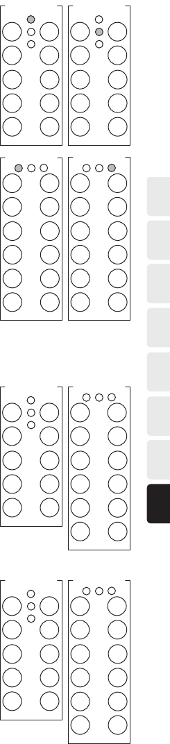
TRANSMITTER
Pictures of the transmitter can be found on the fold-out page.
Technical Specifications
860TX-10 860TX-12
Stop button Stop button
10 two way push buttons 12 two way push buttons
Internal rechargeable battery External rechargeable battery
Radio: PLL Synthesizer Radio: PLL Synthesizer
69 different frequencies, 433.075 - 434.775 MHz 69 different frequencies, 433.075 - 434.775 MHz
Enclosure size: 160x70x35 mm Enclosure size: 210x80x40 mm
Weight: approx. 270 g Weight: approx. 400 g
Enclosure class: IP 54 Enclosure class: IP 65
HOW TO START THE TRANSMITTER
1. The stop button must be pulled out.
2. Press the start buttons simultaneously for at least 1 second.
3. Release the start buttons.
4. LED 3 is lit green to indicate the transmitter is running.
HOW TO START A TRANSMITTER WITH A PIN CODE
1. The stop button must be pulled out.
2. Press the start buttons simultaneously for at least 1 second.
3. Release the buttons.
– The yellow (2) and green (3) LEDs flash.
4. Enter the PIN code (4 numbers).
– The green LED (3) lights continuously.
If the wrong PIN code is entered the transmitter will switch itself off.
HOW TO TURN OFF THE TRANSMITTER
To turn off the transmitter press the stop button. All relays in the receiver are disconnected when the stop
button is pressed on the transmitter.
HOW TO CHARGE THE TRANSMITTER:
Pictures of charging the transmitter can be found on the fold-out page.
• The 860TX-10 transmitter is supplied with an internal rechargeable battery and an integrated charger.
• The 860TX-12 transmitter is supplied with an external rechargeable battery and a charger unit.
The LED in the transmitter indicates red or green depending on the status of the battery. The operating time
for the transmitter is approx. 30 hours for the 860TX-10 and 20 hours for the 860TX-12 with continuous
usage. The LED (3) changes colour to red when it is time to charge the battery and approximately 10 % of the
battery capacity remains.
The LED in the 860TX-10 transmitter and in the 860TX-12 charger unit, will remain red during charging
(full charge time: approx. 4 hours) until fully charged when it changes colour to green. The battery can not be
overcharged.
NOTE! The life span of the battery increases if you wait until the LED changes to red before recharging. However, it
should be charged at least once every second month.
– Charging: 12V-35V DC (500 mA) or 230V AC via an adaptor.

206
EN DE FR ES NL SE NO DK
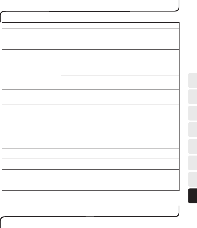
RECEIVER 860RX
Pictures of the receiver can be found on the fold-out page.
Technical Specifications
Relay outputs: Midi: 10+2 for stop function, Maxi: 24+2 for stop function
Stop relay: potential free, makes 8A AC1
Function relay: potential free, breaks/makes 16A AC1
Radio: PLL synthesizer
69 different frequencies, 433.075 - 434.775 MHz
Size: 250x175x75 mm
Enclosure class: IP 65
Antenna connector: BNC
SUPPLY VOLTAGE POWER CONSUMPTION: MIN. POWER CONSUMPTION: MAX.
12V DC 150 mA 1 A
24V DC 60 mA 600 mA
24V AC 80 mA 800 mA
48V AC 100 mA 400 mA
115V AC 70 mA 200 mA
230V AC 25 mA 100 mA
The different status LEDs on the receiver
Yellow LED 2 lights when the receiver has the correct supply voltage.
Yellow LEDs 6 and 10 flash 1, 2 or 3 times, depending on how many transmitters are programmed on the
receiver.
Green LED 12 lights when the receiver receives radio signals (433.075 – 434.775 MHz).
Green LEDs 4 and 8 lights when the receiver has locked on a transmitter.
Red LEDs 5 and 9 indicate that there is a fault on the receiver.
Each relay is fitted with a red LED that lights when the relay is active.
207
ESFRDEEN DKNOSENL
123
SR1
SR1
4 5
6
7 8 9 10
8 9 10 11 12 13 14 15 16 17 18 19 20 21 22 23 24 25 26 27 28 29 30 31 32 33 34 35 36 37 38 39 40 41
1 2 3 4 5 6 7
23 0V A C
11 5V A C
48 V AC
0 V
24V AC /D C
12V DC
0 V
C NO NC C NO NC C NO NC CNO NC C NO NC C NO NC C NO NC
SR2
1 2 3 4 5 6
SR1
C NO NC C NO NC C NO NC
7 8 9 10
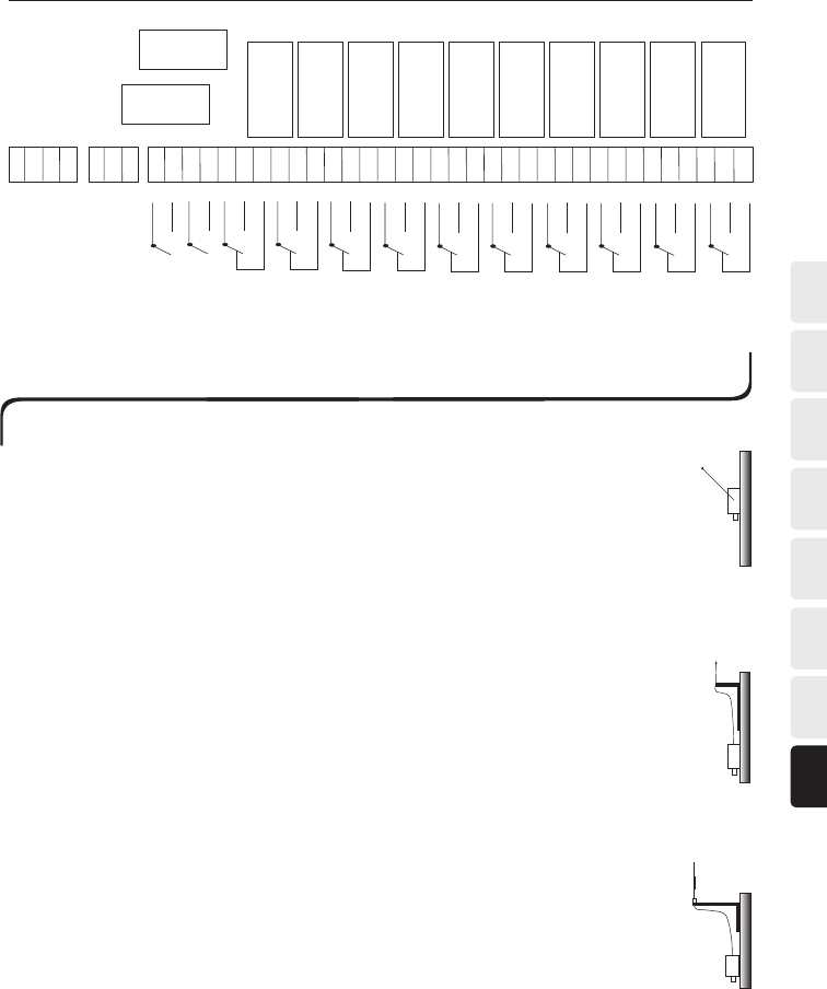
The receiver should be installed:
• As far as possible, protected from the wind and weather. Do not install the receiver in such a
way that it can be exposed to exceptional moist conditions such as high-pressure washing
• With the cable glands downward.
Placement of the receiver antenna:
• Place the antenna high above the ground.
• The antenna should not be in the vicinity of metal objects such as girders, electrical cables and
other antennas.
The 1/2-wave antenna is ground plane independent, which is beneficial and a great advantage when
there is not a “natural” ground plane such as a metal plate or vehicle roof. It is important that the
antenna is angled out from the wall if the receiver is installed on a wall.
The 1/4-433K antenna with three metre coaxial cable makes it possible to place the antenna high
and unobstructed. To get the best possible range with the 1/4-433K antenna it should be installed
on a flat roof, free from other metal objects and antennae. When installing the antenna on a vehicle
it is suitable to use a vehicle bracket (F1).
The 5/8-wave antenna with three metre coaxial cable makes it possible to place the antenna high
and unobstructed. To get the best possible range with the 5/8-wave antenna it should be installed
on a flat roof, free from other metal objects and antennae. When installing the antenna on a wall it
is suitable to use a wall bracket (VM1).
5/8
1/4-433K
1/2
INSTALLING THE RECEIVER AND THE RECEIVER ANTENNA
CONNECTING THE RECEIVER
To utilize the safety of the system, be sure to use relays SR1, SR2 as stop relays in the safety circuitry of the
object to be controlled.

208
EN DE FR ES NL SE NO DK
CO-PROGRAMMING THE TRANSMITTER AND RECEIVER
The receiver can be programmed to accept up to three different transmitters, where each transmitter has its
own unique code. The LEDs 6 and 10 on the receiver indicate how many transmitters have been programmed
in the receiver.
Not flashing = No transmitter has been programmed
1 flash = 1 transmitter has been programmed
2 flashes = 2 transmitters have been programmed
3 flashes = 3 transmitters have been programmed
1. On the receiver: turn the function selector switch 2 to the ON position.
2. Press the reset button on the receiver.
– The green, red and yellow LEDs 4-6 and 8-10 lights.
3. Release the reset button.
– The green (4 and 8) and red (5 and 9) LEDs go out. The yellow LEDs 6 and 10 light continuously.
(If the yellow and red LEDs flash alternately then three transmitters have already been programmed on the
receiver, so all the transmitters must be erased and reprogrammed.)
4. Start the transmitter by pressing the start buttons simultaneously for at least 1 second.
– Release the buttons.
5. Press the start buttons simultaneously again until the yellow LEDs 6 and 10 on the receiver start to flash.
The receiver has found the transmitter.
6 On the receiver: turn the function selector switch 2 to the OFF position.
7 The transmitter has been programmed.
NOTE! Do not forget to complete the Settings form after programming!
ERASING ALL THE TRANSMITTERS IN THE RECEIVER
ON THE RECEIVER
1. Turn the function selector switch 2 to the ON position.
2. Press the reset button.
– The green (4 and 8), red (5 and 9) and yellow (6 and 10) LEDs light continuously.
3. Release the reset button.
– The green (4 and 8) and red (5 and 9) LEDs go out. The yellow (6 and 10) LEDs light continuously.
(If the yellow and red LEDs flash alternately this means 3 transmitters have been programmed in the receiver.)
4. Turn switch 2 to the OFF position.
5. Turn switch 2 to the ON position within 2 seconds.
– The yellow (6 and 10) LEDs flash and the receiver has been erased.
6. Turn switch 2 to the OFF position.
REPLACE A TRANSMITTER IN THE RECEIVER
It is possible to erase a programmed transmitter and program a new transmitter into the receiver without
putting the receivers DIP-switch in program mode. It is very helpful if you would like to replace a transmitter
without going up to a high mounted receiver on a crane. This operation will be done from the transmitter that
should be programmed into the receiver.

209
ESFRDEEN DKNOSENL
DO THE FOLLOWING TO REPLACE A TRANSMITTER:
1. Check the ID-code on the transmitter that should be erased from the receiver.
2. Start-up the transmitter that should be programmed into the receiver. You must be in the working range of
the receiver that should be erased and programmed.
3. Press the stop button on the transmitter.
– The red LED 3 lights continuously for 1 second, then (on the transmitter) the yellow LED 2 lights continuously
and the red LED 3 starts to flash.
4. Enter the PIN-code. You have 2 seconds per button. If the time elapses, the transmitter will switch off.
– If no PIN-code has been programmed you should enter 4 zeros (0000).
5. If the PIN-code is ok, the transmitters yellow LED 2 goes out.
If the wrong PIN-code is entered the transmitter will switch off.
6. Enter the ID-code for the transmitter that should be erased (max 5 numbers). You have 2 seconds per but-
ton.
Please note that no zeros should be entered if the ID-code is less then 5 numbers. For example: ID-code 678
should be 6, 7, 8 and not 0, 0, 6, 7, 8.
7. When the ID-code is entered the transmitters red LED 3 lights continuously and the yellow LED 2 will
flash. The transmitter will now send a command (10s) to the receiver to erase the selected ID-code and
program the ID-code for the operating transmitter.
8. When the transmitter has switched off it can be started-up and used with the selected receiver.
Please note that the erased transmitter can no longer be used together with the receiver.
LOCK/UNLOCK A RECEIVER
When a transmitter that is programmed to a receiver starts, the receiver “locks” on to the transmitter’s
ID code. In this position the receiver will only accept this transmitter (even if more transmitters have been
programmed on the receiver). The green LEDs 4 and 8 lights on the receiver to confirm that only the selected
transmitter can be used.
When another transmitter is to be used the receiver must first be unlocked. Another programmed transmitter
can then be locked on to the receiver.
UNLOCKING THE RECEIVER
The transmitter to be logged must be started/logged on.
On the logged on transmitter (Alternative 1):
1. Press the stop button on the transmitter.
– The red LED 3 lights continuously for 1 second, then (on the transmitter) the yellow LED 2 lights continuously
and the red LED 3 starts to flash.
2. Enter the PIN code. You have 2 seconds per button.
– If no PIN code has been programmed you should enter 4 zeros (0000) to unlock the receiver.
3. If the PIN code is approved, the transmitter sends a signal to unlock the receiver. The transmitter switches
itself off and is now logged out.
– The green LEDs 4 and 8 on the receiver go out and it is now possible for another programmed transmitter to
be logged on.
If the wrong PIN code is entered the transmitter will switch itself off without unlocking the receiver.
On the logged on transmitter (Alternative 2):
1. Press push button 9 (left start button) on the transmitter and then press stop button.
– The red LED 3 lights continuously for 1 second, then (on the transmitter) the yellow LED 1 flashes. The
transmitter then automatically sends a signal to unlock the receiver.. The transmitter switches itself off when
this operation is done and the transmitter is logged out. The green LEDs 4 and 8 on the receiver go out and it
is now possible for another programmed transmitter to be logged on. NOTE! this way of unlocking the
receiver requires that no dangerous function is placed on button 9 (left start button)

210
EN DE FR ES NL SE NO DK
UNLOCKING THE RECEIVER WITHOUT A TRANSMITTER
1. Turn switch 2 to the ON position.
2. Press down the reset button.
– Green (4 and 8), red (5 and 9) and yellow (6 and 10) LEDs light continuously.
3. Release the reset button.
– The green (4 and 8) and red (5 and 9) LEDS go out. Yellow LED (6 and 10) lights continuously.
4. Turn switch 2 to the OFF position.
5. Yellow (6 and 10) LEDs go out.
The receiver can now be logged on to another transmitter.
RADIO MODULE MODE
If the 69 channel radio module is mounted in the transmitter it is possible to program the module to operate
in 3 modes. This is very useful when the 69 channel transmitter is used with a receiver with the 16+16 radio
modul (old 860 version). If the 16+16 channel radio module is mounted in the transmitter it is not possible to
select these modes.
Mode Channels
0 1-69
1 1-16
2 17-32
PROGRAMMING RADIO MODULE MODE
1. Start the transmitter by pressing the start buttons for at least 1 second.
– The red LED 3 lights continuously.
2. Release left start button, but hold right start button.
NOTE! You have 0.3 seconds to perform the action in step 3.
3. Release right start button and then select button 2 for programming radio module mode. (If you do not
press any of the function buttons the transmitter starts.)
– The yellow LED 2 lights continuously and the green LED 3 starts to flash.
4. Enter the safety code 5, 3, 4, 6. You have 5 seconds per button, if the time elapses the transmitter switches
off.
– The green LED 3 flashes and the yellow LED 2 goes out if the safety code is correct.
5. Enter a 0 for mode 0 (1-69), a 1 for mode 1 (1-16) or a 2 for mode 2 (17-32).
– When you have entered the transmitting mode the yellow LED 1 flashes 3 times and the transmitting mode is
programmed. The transmitter switches itself off.
6. Restart the transmitter.

211
ESFRDEEN DKNOSENL
CHANGING THE FREQUENCY
Programming/changing the frequency can only be carried out with the help of the transmitter.
Decide which channel/frequency you wish to transmit on by using the table below before you start program-
ming. The receiver automatically detects and changes to the new frequency.
FREQUENCY TABLE (69 CHANNELS)
CHANNEL FREQUENCY CHANNEL FREQUENCY
01 433,075 MHz 36 433,950 MHz
02 433,100 MHz 37 433,975 MHz
03 433,125 MHz 38 434,000 MHz
04 433,150 MHz 39 434,025 MHz
05 433,175 MHz 40 434,050 MHz
06 433,200 MHz 41 434,075 MHz
07 433,225 MHz 42 434,100 MHz
08 433,250 MHz 43 434,125 MHz
09 433,275 MHz 44 434,150 MHz
10 433,300 MHz 45 434,175 MHz
11 433,325 MHz 46 434,200 MHz
12 433,350 MHz 47 434,225 MHz
13 433,375 MHz 48 434,250 MHz
14 433,400 MHz 49 434,275 MHz
15 433,425 MHz 50 434,300 MHz
16 433,450 MHz 51 434,325 MHz
17 433,475 MHz 52 434,350 MHz
18 433,500 MHz 53 434,375 MHz
19 433,525 MHz 54 434,400 MHz
20 433,550 MHz 55 434,425 MHz
21 433,575 MHz 56 434,450 MHz
22 433,600 MHz 57 434,475 MHz
23 433,625 MHz 58 434,500 MHz
24 433,650 MHz 59 434,525 MHz
25 433,675 MHz 60 434,550 MHz
26 433,700 MHz 61 434,575 MHz
27 433,725 MHz 62 434,600 MHz
28 433,750 MHz 63 434,625 MHz
29 433,775 MHz 64 434,650 MHz
30 433,800 MHz 65 434,675 MHz
31 433,825 MHz 66 434,700 MHz
32 433,850 MHz 67 434,725 MHz
33 433,875 MHz 68 434,750 MHz
34 433,900 MHz 69 434,775 MHz
35 433,925 MHz

212
EN DE FR ES NL SE NO DK
FREQUENCY TABLE (16+16 CHANNELS)
CHANNEL FREQUENCY STRAP CHANNEL FREQUENCY STRAP
01 434.650 MHz Open 17 434.625 MHz Closed
02 434.600 MHz Open 18 434.575 MHz Closed
03 434.550 MHz Open 19 434.525 MHz Closed
04 434.500 MHz Open 20 434.475 MHz Closed
05 434.450 MHz Open 21 434.425 MHz Closed
06 434.400 MHz Open 22 434.375 MHz Closed
07 434.350 MHz Open 23 434.325 MHz Closed
08 434.300 MHz Open 24 434.275 MHz Closed
09 434.250 MHz Open 25 434.225 MHz Closed
10 434.200 MHz Open 26 434.175 MHz Closed
11 434.150 MHz Open 27 434.125 MHz Closed
12 434.100 MHz Open 28 434.075 MHz Closed
13 434.050 MHz Open 29 434.025 MHz Closed
14 434.000 MHz Open 30 434.975 MHz Closed
15 433.950 MHz Open 31 433.925 MHz Closed
16 433,900 MHz Open 32 433,875 MHz Closed
CHANGING THE FREQUENCY
1. Start the transmitter by pressing the start buttons for at least 1 second.
– The red LED 3 lights continuously.
2. Release left start button, but hold right start button.
NOTE! You have 0.3 seconds to perform the action in step 3.
3. Release right start button and then select button 2 for the frequency. (If you do not press any of the function
buttons the transmitter starts.)
– The yellow LED 2 lights continuously and the green LED 3 starts to flash.
4. Enter the safety code 1, 2, 3, 4. You have 5 seconds per button, if the time elapses the transmitter switches
off.
– The green LED 3 flashes and the yellow LED 2 goes out if the safety code is correct.
5. Select the channel/frequency. For example, channel 02: first press the 0 button and then the 2 button.
– The yellow LED 1 lights each time an accepted button is pressed. Once you have selected the frequency the
yellow LED (1) flashes 3 times and programming and the change of frequency are then complete.
6. Restart the transmitter.
Do not forget to write down the changes on the Settings form after programming!

213
ESFRDEEN DKNOSENL
STEP UP/DOWN IN FREQUENCY
It is possible to move up or down in frequency before the transmitter is started-up.
1. Start the transmitter by pressing the start buttons for at least 1 second.
2. Release left start button, but hold right start button.
3. Press button 1 (yellow LED 1 indicates) to move up one step in frequency.
Press button 2 (yellow LED 2 indicates) to move down one step.
– Example: If you like to move up 5 frequency steps, you need to press button 1 five times.
4. Release all buttons and the transmitter starts on the new frequency.
AUTOMATIC SHUT-OFF
The transmitter can be programmed with an automatic shut-off function once the last command has been given
to conserve battery capacity. See the time options below.
Time option
Button 0 = No automatic shut-off.
Button 1 = Automatic shut-off after 2 minutes.
Button 2 = Automatic shut-off after 6 minutes.
Button 3 = Automatic shut-off after 12 minutes.
PROGRAMMING AUTOMATIC SHUT-OFF:
1. Start the transmitter by pressing the start buttons for at least 1 second.
– The red LED 3 lights continuously.
2. Release left start button, but hold right start button.
NOTE! You have 0.3 seconds to perform the action in step 3.
3. Release right start button and then select button 3 for automatic shut-off. (If you do not press any of the
function buttons the transmitter starts.)
– The yellow LED 2 lights continuously and the green LED 3 starts to flash.
4. Enter the safety code 1, 2, 3, 4. You have 5 seconds per button; if the time elapses the transmitter switches
off.
– The green LED 3 flashes and the yellow LED 2 goes out if the safety code is correct.
5. Select the required time option (see the options above).
– The yellow LED 1 lights each time an accepted button is pressed. Once you have selected an option the yellow
LED (1) flashes 3 times and programming is complete.
6. Restart the transmitter.
Do not forget to write down the changes on the Settings form after programming!

214
EN DE FR ES NL SE NO DK
PIN CODE FUNCTION
It is possible to program 10 PIN codes on each transmitter.
PROGRAMMING A PIN CODE:
1. Start the transmitter by pressing the start buttons for at least 1 second.
– The red LED 3 lights continuously.
2. Release left start button, but hold right start button.
NOTE! You have 0.3 seconds to perform the action in step 3.
3. Release right start button and select button 4 for the PIN code. (If you do not press any of the function but-
tons the transmitter starts.)
– The yellow LED 2 lights continuously and the green LED 3 starts to flash.
4. Enter the safety code 1, 2, 3, 4. You have 5 seconds per button, if the time elapses the transmitter switches
off.
– The yellow LED 1 lights each time an accepted button is pressed.
– The green LED 3 flashes and the yellow LED 2 goes out if the safety code is correct.
5. Select the number (button) the PIN code should be programmed to (0-9).
– The green LED 3 flashes.
– The yellow LED 2 will light if the number is used by a PIN code.
6. Select en PIN code by entering a combination of 4 numbers. Confirm the code by repeating it.
– Once you have selected a PIN code the yellow LED (1) flashes 3 times and programming is complete. The
transmitter switches itself off.
7. Restart the transmitter.
NOTE! The PIN code combination 0000 cannot be used.
Do not forget to write down the changes on the Settings form after programming!
CHANGING/ERASING THE PIN CODE:
1. Start the transmitter by pressing the start buttons for at least 1 second.
– The red LED 3 lights continuously.
2. Release left start button, but hold right start button.
NOTE! You have 0.3 seconds to perform the action in step 3.
3. Release right start button and select button 4 for the PIN code. (If you do not press any of the function but-
tons the transmitter starts.)
– The yellow LED 2 lights continuously and the green LED 3 starts to flash.
4. Enter the safety code 1, 2, 3, 4. You have 5 seconds per button, if the time elapses the transmitter switches
off.
– The yellow LED 1 lights each time an accepted button is pressed.
– The green LED 3 flashes and the yellow LED 2 goes out if the safety code is correct.
5. Press the number (0-9) which the PIN code is programmed under.
– The yellow LED 2 lights continuously.
6. Enter the existing four digit PIN code.
– The yellow LED 2 goes out if the PIN code is correct.
7. Changing the PIN code: Select a PIN code by entering a combination of 4 numbers. Confirm the code by
repeating it.
– Once you have selected a PIN code the yellow LED (1) flashes 3 times and programming is complete.
8. Erasing the PIN code: Enter four zeros (0000) and confirm by entering the four zeros (0000) again.
– The yellow LED (1) flashes 3 times and the erasing procedure is complete. The transmitter switches off.
9. Restart the transmitter.

215
ESFRDEEN DKNOSENL
ERASING ALL PIN-CODES
You can, if necessary, erase all the PIN codes on the transmitter.
ERASE ALL THE PIN CODES ON THE TRANSMITTER:
1. Start the transmitter by pressing the start buttons for at least 1 second.
– The red LED 3 lights continuously.
2. Release left start button, but hold right start button.
NOTE! You have 0.3 seconds to perform the action in step 3.
3. Release right start button and then select button 8 to erase the PIN codes.
– The yellow LED 2 lights continuously and the green LED 3 flashes.
4. Enter the code 7, 1, 0, 4, 2, 1.
– Once you have entered the code the yellow LED (1) flashes 3 times and the erasing procedure is complete.
The transmitter switches itself off.
5. Restart the transmitter.
TIME DELAY BETWEEN PUSHBUTTONS
It is possible to program time delays between pushbuttons and between first and second step in the pushbut-
ton. The following options are possible to program:
CODE PUSHBUTTON DELAY COMMENTS
0 1 Pushbutton 1 (also used as button 11) Time delay function between the
first and second step for the same
pushbutton
0 2 Pushbutton 2 (also used as button 12)
0 3 Pushbutton 3 (also used as button 13)
0 4 Pushbutton 4 (also used as button 14)
0 5 Pushbutton 5 (also used as button 15)
0 6 Pushbutton 6 (also used as button 16)
0 7 Pushbutton 7 (also used as button 17)
0 8 Pushbutton 8 (also used as button 18)
0 9 Pushbutton 9 (also used as button 19)
1 0 Pushbutton 10 (also used as button 20)
2 2 * Pushbutton 21 (also used as button 23)
2 3 * Pushbutton 22 (also used as button 24)
1 1 Pushbutton 1 and 2 Time delay function between two dif-
ferent pushbuttons
1 2 Pushbutton 3 and 4
1 3 Pushbutton 5 and 6
1 4 Pushbutton 7 and 8
1 5 Pushbutton 9 and 10
2 4 * Pushbutton 21 and 22
1 6 Time delay options, code 01 to 15 (+ 22 to 24 *) Pre-set programming for all pushbut-
tons in the specified code range
1 7 Time delay options, code 01 to 10 (+ 22 to 23 *)
1 8 Time delay options, code 11 to 15 (+ 24 *)
1 9 Time delay options, code 01 to 06
2 0 Time delay options, code 11 to 13
2 1 Time delay options, code 01 to 06 + 11 to13
* Only on 860TX-12
216
EN DE FR ES NL SE NO DK
CODE TIME DELAY COMMENTS
0 No time delay Sets the time delay in seconds
1 0,3s
2 0,5s
3 1s
4 1,5s
5 3s
PROGRAMMING TIME DELAY BETWEEN PUSHBUTTONS
1. Start the transmitter by pressing the start buttons for at least 1 second.
– The red LED 3 lights continuously.
2. Release left start button, but hold right start button.
NOTE! You have 0.3 seconds to perform the action in step 3.
3. Release right start button and then select button 6 for programming time delay between pushbuttons. (If
you do not press any of the function buttons the transmitter starts.)
– The yellow LED 2 lights continuously and the green LED 3 starts to flash.
4. Enter the safety code: 8, 5, 3, 2, 4, 6. You have 5 seconds per button, if the time elapses the transmitter
switches off.
– The green LED 3 flashes and the yellow LED 2 goes out if the safety code is correct.
5. Enter the pushbutton delay code (two digits) and time code (one digit). The yellow LED 1 lights each time
an accepted button is pressed.
– Once you have selected option and time the yellow LED (1) flashes 3 times and programming is complete.
7. Restart the transmitter.
FUNCTION SELECTOR
The functions in the table can be programmed by using the buttons on the transmitter and by setting the func-
tion selector switches. Note that the table is only an outline and all function options are described in detail in
the chapters that follow the table.
No. of
functions
Function
selection
TX (trans-
mitter)
LED TX
(transmit-
ter)
Function
selection
RX (re-
ceiver)
Receiver
model
(Maxi or
Midi)
Function selector switch
(receiver) 4, 6, 7, 8.
Comments
10x1 0 - A MIDI OFF.OFF.OFF.OFF Only 1 receiver
4x2+2x1 0 - B MIDI OFF.OFF.OFF.ON Only 1 receiver
6x2+1x1 0 - C MIDI OFF.OFF.ON.OFF Only 1 receiver
10x1 1 1 D MIDI OFF.OFF.OFF.OFF Receiver 1 (8x1)
10x1 1 2 D MIDI ON.OFF.OFF.OFF Receiver 2 (8x1)
10x1 1 1+2 D MIDI *.OFF.OFF.OFF Receiver 1+2 (8x1)
10x1 2 1 E MIDI OFF.OFF.OFF.OFF Receiver 1 (8x1)
10x1 2 2 E MIDI ON.OFF.OFF.OFF Receiver 2 (8x1)
10x1 3 1 F MIDI OFF.OFF.OFF.OFF Receiver 1 (9x1)
10x1 3 2 F MIDI ON. OFF. OFF. OFF Receiver 2 (9x1)
4x2+2x1 1 1 G MIDI OFF.OFF.OFF.ON Receiver 1 (4x2+2x1)
4x2+2x1 1 2 G MIDI ON.OFF.OFF.ON Receiver 2 (4x2+2x1)
4x2+2x1 1 1+2 G MIDI *.OFF.OFF.ON Receiver 1+2
(4x2+2x1)
4x2+2x1 2 1 H MIDI OFF.OFF.OFF.ON Receiver 1 (4x2+2x1)
4x2+2x1 2 2 H MIDI ON.OFF.OFF.ON Receiver 2 (4x2+2x1)

217
ESFRDEEN DKNOSENL
No. of
functions
Function
selection
TX (trans-
mitter)
LED TX
(transmit-
ter)
Function
selection
RX (re-
ceiver)
Receiver
model
(Maxi or
Midi)
Function selector switch
(receiver) 4, 6, 7, 8.
Comments
6x2+1x1 1 1 I MIDI OFF.OFF.ON.OFF Receiver 1 (6x2+1x1)
6x2+1x1 1 2 I MIDI ON.OFF.ON.OFF Receiver 2 (6x2+1x1)
6x2+1x1 1 1+2 I MIDI *.OFF.ON.OFF Receiver 1+2
(6x2+1x1)
6x2+1x1 2 1 J MIDI OFF.OFF.ON.OFF Receiver 1 (6x2+1x1)
6x2+1x1 2 2 J MIDI ON.OFF.ON.OFF Receiver 2 (6x2+1x1)
10x2/12x2 0 - K MAXI OFF.OFF.OFF.OFF Only 1 receiver
10x2/12x2 1 1 L MAXI OFF.OFF.OFF.OFF Receiver 1 (8x2)
10x2/12x2 1 2 L MAXI ON.OFF.OFF.OFF Receiver 2 (8x2)
10x2/12x2 1 1+2 L MAXI *.OFF.OFF.OFF Receiver 1+2 (8x2)
10x2/12x2 2 1 M MAXI OFF.OFF.OFF.OFF Receiver 1 (8x2)
10x2/12x2 2 2 M MAXI ON.OFF.OFF.OFF Receiver 2 (8x2)
10x2/12x2 1 1 N MAXI OFF.OFF.ON.ON Lift 1
10x2/12x2 1 2 N MAXI OFF.OFF.ON.ON Lift 2
10x2/12x2 1 1+2 N MAXI OFF.OFF.ON.ON Lift 1+2
10x2/12x2 2 1 O MAXI OFF.OFF.ON.ON Lift 1
10x2/12x2 2 2 O MAXI OFF.OFF.ON.ON Lift 2
10x2/12x2 3 1 P MAXI OFF.ON.OFF.OFF 9+9 (Button 1-9->Re-
lay 1-9)
10x2/12x2 3 2 P MAXI OFF.ON.OFF.OFF 9+9 (Button 1-9>Re-
lay 11-19)
10x2/12x2 0 - Q MAXI OFF.OFF.ON.OFF “6x2+1x1” with MAXI
relay board
10x2/12x2 0 - R MAXI OFF.ON.ON.OFF “6x2+6x1” with MAXI
relay board
* = The function selector switch no 4 can be set to ON or OFF.

218
EN DE FR ES NL SE NO DK
THE TRANSMITTER’S FUNCTION SELECTIONS AND LED INDICATIONS
It is possible to program the function selection on the transmitter. The two yellow LEDs on the transmitter
indicate which receiver/receivers, relay group/groups or the lift on an overhead crane are to be controlled. By
setting the receiver’s function selector switch at the same time a number of different types of relay functions
can be selected (see chapter “The receiver’s function selection/relay functions“).
Once you have programmed the function selections 1-3 the transmitter’s LED 1 will always light when the
transmitter starts.
NOTE! As standard the transmitter is supplied with function selection 0.
FUNCTION SELECTION 0:
With function selection 0 it is only possible to control one receiver. The two yellow LEDs are not used.
The transmitter’s function selection 0 matches with receiver’s function selection; A, B, C, K, Q, R
FUNCTION SELECTION 1:
Using function selection 1 you can control two receivers (receiver 1, receiver 2 or both simultaneously), alter-
natively you can control two lifts on an overhead crane (lift 1, lift 2 or both lifts simultaneously).
By pressing button 7 the yellow LED 1 lights, press button 8 and the yellow LED 2 lights. Press buttons 7 and 8
simultaneously and the LEDs 1 and 2 light.
The transmitter’s function selection 1 matches with receiver’s function selection; D, G, I, L, N
FUNCTION SELECTION 2:
Using function selection 2 you can control two receivers (receiver 1 or receiver 2, but never simultaneously),
alternatively you can control two lifts on an overhead crane (lift 1 or lift 2 but never simultaneously).
By pressing button 7 the yellow LED 1 lights, press button 8 and the yellow LED 2 lights. The yellow LEDs 1 and
2 can never be lit simultaneously.
The transmitter´r function selection 2 matches the receiver’s function selection; E, H, J, M, O
FUNCTION SELECTION 3:
With function selection 3 you can control two receivers (9 single functions on each receiver) or one receiver
(9+9 single functions).
By pressing button 10 (right start button) you switch between lighting the yellow LED 1 or LED 2. The yellow
LEDs 1 and 2 can never be lit simultaneously.
The transmitter function selection 3 matches the receiver’s function selection: F, P

219
ESFRDEEN DKNOSENL
PROGRAMMING THE FUNCTION SELECTION ON THE TRANSMITTER:
1. Start the transmitter by pressing the start buttons for at least 1 second.
– The red LED 3 lights continuously.
2. Release left start button, but hold right start button.
NOTE! You have 0.3 seconds to perform the action in step 3.
3. Release right start button and then select button 1 for function selection. (If you do not press any of the func-
tion buttons the transmitter starts.)
– The yellow LED 2 lights continuously and the green LED 3 starts to flash.
4. Enter the safety code: 1, 2, 3, 4. You have 5 seconds per button, if the time elapses the transmitter switches
off.
– The green LED 3 flashes and the yellow LED 2 goes out if the safety code is correct.
5. Choose the respective function options (button 0, 1, 2 or 3). The yellow LED 1 lights each time an accepted
button is pressed.
– Once you have selected a function option the yellow LED (1) flashes 3 times and programming is complete.
NOTE! The function is deprogrammed using the 0 button.
6. Restart the transmitter by pressing the start buttons.
YELLOW LED/START-UP
If function selection 1 or 2 is programmed in 860 mode it is possible to choose which yellow LED/LED’s that
should be on when starting the transmitter.
Yellow LED start-up options, function selection 1:
• Option 0: No yellow LED’s.
• Option 1: Yellow LED 1 is on.
• Option 2: Yellow LED 2 is on.
• Option 3: Yellow LED 1+2 is on.
Yellow LED start-up options, function selection 2:
• Option 0: No yellow LED’s.
• Option 1: Yellow LED 1 is on.
• Option 2: Yellow LED 2 is on.
PROGRAMMING YELLOW LED/START-UP
1. Start the transmitter by pressing the start buttons for at least 1 second.
– The red LED 3 lights continuously.
2. Release left start button, but hold right start button.
NOTE! You have 0.3 seconds to perform the action in step 3.
3. Release right start button and then select button 1 for function selection. (If you do not press any of the
function buttons the transmitter starts.)
– The yellow LED 2 lights continuously and the green LED 3 starts to flash.
4. Enter the safety code: 7, 4, 8, 3. You have 5 seconds per button, if the time elapses the transmitter switches
off.
– The green LED 3 flashes and the yellow LED 2 goes out if the safety code is correct.
5. Choose the respective yellow LED start-up option (button 0-3).
– The yellow LED 1 lights each time an accepted button is pressed. Once you have selected a function option
the yellow LED (1) flashes 3 times and programming is complete.
6. Restart the transmitter.
220
EN DE FR ES NL SE NO DK
1
3
5
7
9
2
4
6
8
10
1
2
3
Start Start
860TX-10
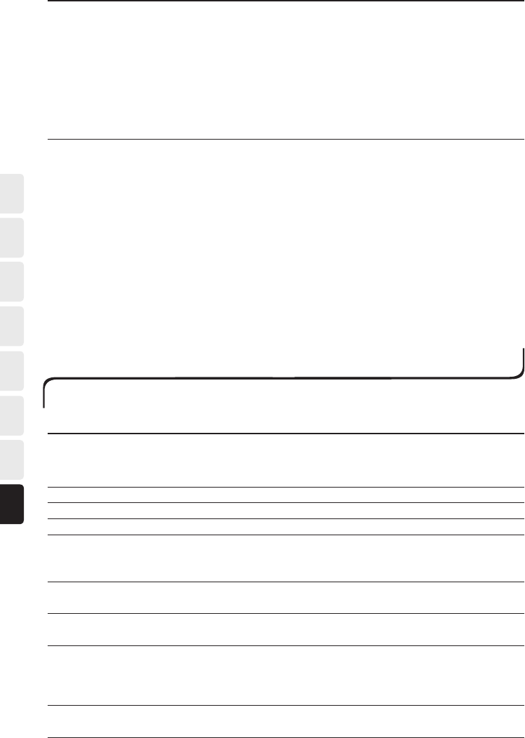
Program the function selection on the receiver:
The function selection on the receiver is programmed by setting the
function selector switches in either the ON or OFF positions. To see how
the switches should be set refer to respective function selections or the
function selection table. (For the transmitter’s matching function selections,
see chapter “The transmitter’s function selections and led indications“.)
Pictures of the receiver can be found on the fold-out page.
RECEIVER 860RX-MIDI
Function selection A:
Relay function: 10 single functions (10x1).
See figure A for which buttons control respective relays.
The function selector switch: 4=OFF, 6=OFF, 7=OFF, 8=OFF
The receiver’s function selection A matches the transmitter’s function
selection 0.
Function selection B:
Relay function: 4 double + 2 single functions (4x2+2x1).
See figure B for which buttons control respective relays.
The function selector switch: 4=OFF, 6=OFF, 7=OFF, 8=ON
The receiver’s function selection B matches the transmitter’s function
selection 0.
Function selection C:
Relay function: 6 double + 1 single functions (6 x 2 + 1x 1).
See figure C for which buttons control respective relays.
The function selector switch: 4=OFF, 6=OFF, 7=ON, 8=OFF
The receiver’s function selection C matches the transmitter’s function
selection 0.
Fig. A
1
3
5
7
2
4
6
8
1 3 2
860TX-12
9 10
Start Start
Fig. B
1/5
3/7
9
2/6
4/8
10
1
2
3
Start Start
860TX-10
1/5
3/7
2/6
4/8
1 3 2
860TX-12
9 10
Start Start
Fig. C
1/7
3/8
5/9
10
2/7
4/8
6/9
1
2
3
Start Start
860TX-10
1/7
3/8
5/9
2/7
4/8
6/9
1 3 2
860TX-12
10
Start Start
THE RECEIVER’S FUNCTION SELECTION/RELAY FUNCTIONS

221
ESFRDEEN DKNOSENL
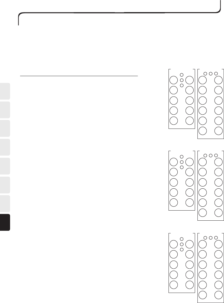
Function selection D:
Relay function: 8 single functions + 2 relays to indicate that the receiver is
selected.
Using the transmitter’s buttons 7 and 8 either receiver 1, 2 or both can be con-
trolled. See figure D for which buttons control respective relays.
Receiver 1:
The function selector switch: 4=OFF, 6=OFF, 7=OFF, 8=OFF
Relay 7 is activated when the yellow LED 1 is lit on the transmitter.
Receiver 2:
The function selector switch: 4=ON, 6=OFF, 7=OFF, 8=OFF
Relay 8 is activated when the yellow LED 2 is lit on the transmitter.
The receiver’s function selection D matches the transmitter’s function selection 1.
Function selection E:
Relay function: 8 single functions + 2 relays to indicate that the receiver is
selected.
Using the transmitter’s buttons 7 and 8 receivers 1 or 2 can be controlled, but
never both receivers simultaneously. See figure E for which buttons control
respective relays.
Receiver 1:
The function selector switch: 4=OFF, 6=OFF, 7=OFF, 8=OFF
Relay 7 is activated when the yellow LED 1 is lit on the transmitter.
Receiver 2:
The function selector switch: 4=ON, 6=OFF, 7=OFF, 8=OFF
Relay 8 is activated when the yellow LED 2 is lit on the transmitter.
The receiver’s function selection E matches the transmitter’s function selection 2.
Function selection F:
Relay function: 9 single functions + 1 relay for indication that the receiver is
selected.
Using the transmitter’s button 10 receivers 1 or 2 can be controlled, but never
both receivers simultaneously. See figure F for which buttons control respective
relays.
Receiver 1:
The function selector switch: 4=OFF, 6=OFF, 7=OFF, 8=OFF
Relay 10 is activated when the yellow LED 1 is lit on the transmitter.
Receiver 2:
The function selector switch: 4=ON, 6=OFF, 7=OFF, 8=OFF
Relay 10 is activated when the yellow LED 2 is lit on the transmitter.
The receiver’s function selection F matches the transmitter’s function selection 3.
Fig. D
1
3
5
(7)
9
2
4
6
(8)
10
1
2
3
Start Start
860TX-10
1
3
5
(7)
2
4
6
(8)
1 3 2
860TX-12
9 10
Start Start
1
3
5
(7)
9
2
4
6
(8)
10
1
2
3
Start Start
860TX-10
Fig. E
1
3
5
(7)
2
4
6
(8)
1 3 2
860TX-12
9 10
Start Start
Fig. F
1
3
5
7
9
2
4
6
8
(10)
1
2
3
Start Start
860TX-10
1
3
5
7
2
4
6
8
1 3 2
860TX-12
9 (10)
Start Start
222
EN DE FR ES NL SE NO DK
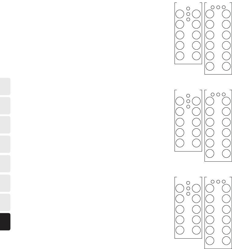
Function selection G:
Relay function: 4 double + 2 single functions (4x2+2x1).
Using the transmitter’s buttons 7 and 8 either receiver 1, 2 or both can be
controlled. See figure G for which buttons control respective relays.
Receiver 1:
The function selector switch: 4=OFF, 6=OFF, 7=OFF, 8=ON
Receiver 2:
The function selector switch: 4=ON, 6=OFF, 7=OFF, 8=ON
The receiver’s function selection G matches the transmitter’s function
selection 1.
Function selection H:
Relay function: 4 double + 2 single functions (4x2+2x1)
Using the transmitter’s buttons 7 and 8 receivers 1 or 2 can be controlled,
but never both receivers simultaneously. See figure H for which buttons
control respective relays.
Receiver 1:
The function selector switch: 4=OFF, 6=OFF, 7=OFF, 8=ON
Receiver 2:
The function selector switch: 4=ON, 6=OFF, 7=OFF, 8=ON
The receiver’s function selection H matches the transmitter’s function
selection 2.
Function selection I:
Relay function: 6 double + 1 single function (6x2+1x1)
Using the transmitter’s buttons 7 and 8 either receiver 1, 2 or both can be
controlled. See figure I for which buttons control respective relays.
Receiver 1:
The function selector switch: 4=OFF, 6=OFF, 7=ON, 8=OFF
Receiver 2:
The function selector switch: 4=ON, 6=OFF, 7=ON, 8=OFF
The receiver’s function selection I matches the transmitter’s function selec-
tion 1.
1/7
3/8
5/9
10
2/7
4/8
6/9
1
2
3
Start Start
860TX-10
Fig. I
1/7
3/8
5/9
2/7
4/8
6/9
1 3 2
860TX-12
10
Start Start
Fig. H
1/5
3/7
9
2/6
4/8
10
1
2
3
Start Start
860TX-10
1/5
3/7
2/6
4/8
132
860TX-12
910
Start Start
Fig. G
1/5
3/7
9
2/6
4/8
10
1
2
3
Start Start
860TX-10
1/5
3/7
2/6
4/8
1 3 2
860TX-12
9 10
Start Start
223
ESFRDEEN DKNOSENL
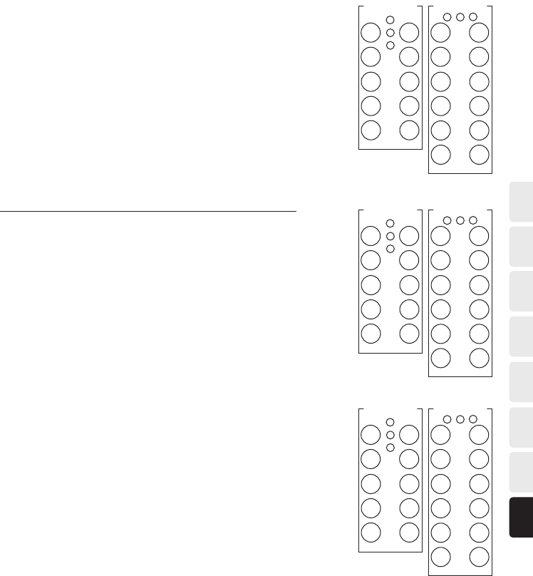
Function selection J:
Relay function: 6 double + 1 single function (6x2+1x1)
Using the transmitter’s buttons 7 and 8 receivers 1 or 2 can be control-
led, but never both receivers simultaneously. See figure J for which buttons
control respective relays.
Receiver 1:
The function selector switch: 4=OFF, 6=OFF, 7=ON, 8=OFF
Receiver 2:
The function selector switch: 4=ON, 6=OFF, 7=ON, 8=OFF
The receiver’s function selection J matches the transmitter’s function selec-
tion 2.
RECEIVER 860RX-MAXI
The relay functions are depending on the receiver.
Function selection K:
Relay function: 20/24 double functions (10x2/12x2).
See figure K for which buttons control respective relays.
The function selector switch: 4=OFF, 6=OFF, 7=OFF, 8=OFF
The receiver’s function selection K matches the transmitter’s function selec-
tion 0.
Function selection L:
Relay function: 8/10 double functions + 2 relays to indicate that the receiver
is selected.
Using the transmitter’s buttons 7 and 8 either receiver 1, 2 or both can be
controlled. See figure L for which buttons control respective relays.
Receiver 1:
The function selector switch: 4=OFF, 6=OFF, 7=OFF, 8=OFF
Relay 7 is activated when the yellow LED 1 is lit on the transmitter.
Receiver 2:
The function selector switch: 4=ON, 6=OFF, 7=OFF, 8=OFF
Relay 8 is activated when the yellow LED 2 is lit on the transmitter.
The receiver’s function selection L matches the transmitter’s function selec-
tion 1.
Fig. J
1/7
3/8
5/9
10
2/7
4/8
6/9
1
2
3
Start Start
860TX-10
1/7
3/8
5/9
2/7
4/8
6/9
1 3 2
860TX-12
10
Start Start
Fig. K
1/11
3/13
5/15
7/17
9/19
2/12
4/14
6/16
8/18
10/20
1
2
3
Start Start
860TX-10
1/11
3/13
5/15
7/17
2/12
4/14
6/16
8/18
132
860TX-12
21/23
9/19
22/24
10/20
Start Start
Fig. L
1/11
3/13
5/15
(7)
9/19
2/12
4/14
6/16
(8)
10/20
1
2
3
Start Start
860TX-10
1/11
3/13
5/15
(7)
2/12
4/14
6/16
(8)
1 3 2
860TX-12
21/23
9/19
22/24
10/20
Start Start
224
EN DE FR ES NL SE NO DK
Function selection M:
Relay function: 8/10 double functions + 2 relays to indicate that the receiver
is selected.
Using the transmitter’s buttons 7 and 8 receivers 1 or 2 can be controlled,
but both receivers simultaneously. See figure M for which buttons control
respective relays.
Receiver 1:
The function selector switch: 4=OFF, 6=OFF, 7=OFF, 8=OFF
Relay 7 is activated when the yellow LED 1 is lit on the transmitter.
Receiver 2:
The function selector switch: 4=ON, 6=OFF, 7=OFF, 8=OFF
Relay 8 is activated when the yellow LED 2 is lit on the transmitter.
The receiver’s function selection M matches the transmitter’s function selec-
tion 2.
Function selection N:
Relay function: 8/10 double functions + 2 relays to indicate which lift is
selected.
Using the transmitter’s buttons 7 and 8 you can control lift 1, 2 or both
simultaneously on an overhead crane. See figure N for which buttons control
respective relays.
The function selector switch: 4=OFF, 6=OFF, 7=ON, 8=ON
Relay 7 is activated when the yellow LED 1 is lit on the transmitter.
Relay 8 is activated when the yellow LED 2 is lit on the transmitter.
The receiver’s function selection N matches the transmitter’s function selec-
tion 1.
Function selection O:
Relay function: 8/10 double functions + 2 relays to indicate which lift is
selected.
Using the transmitter’s buttons 7 and 8 you can control lift 1 or 2 on an over-
head crane, but never simultaneously. See figure O for which buttons control
respective relays.
The function selector switch: 4=OFF, 6=OFF, 7=ON, 8=ON
Relay 7 is activated when the yellow LED 1 is lit on the transmitter.
Relay 8 is activated when the yellow LED 2 is lit on the transmitter.
The receiver’s function selection 0 matches the transmitter’s function selec-
tion 2.
Fig. N
1/11
3/13
5/15
(7)
9/19
2/12
4/14
6/16
(8)
10/20
1
2
3
Start Start
860TX-10
1/11
3/13
5/15
(7)
2/12
4/14
6/16
(8)
1 3 2
860TX-12
21/23
9/19
22/24
10/20
Start Start
Fig. O
1/11
3/13
5/15
(7)
9/19
2/12
4/14
6/16
(8)
10/20
1
2
3
Start Start
860TX-10
1/11
3/13
5/15
(7)
2/12
4/14
6/16
(8)
1 3 2
860TX-12
21/23
9/19
22/24
10/20
Start Start
1/11
3/13
5/15
(7)
9/19
2/12
4/14
6/16
(8)
10/20
1
2
3
Start Start
860TX-10
Fig. M
1/11
3/13
5/15
(7)
2/12
4/14
6/16
(8)
1 3 2
860TX-12
21/23
9/19
22/24
10/20
Start Start
225
ESFRDEEN DKNOSENL
1
3
5
7
9
2
4
6
8
(10)
1
2
3
Start Start
860TX-10
Fig. P
11
13
15
17
12
14
16
18
1 3 2
860TX-12
23
19
24
(20)
Start Start
Fig. Q
1/7
+11
3/8
5/9
13
10/19
2/7
+12
4/8
6/9
14/18
16/20
1
2
3
Start Start
860TX-10
1/7
+11
3/8
5/9
13
2/7
+12
4/8
6/9
14/18
132
860TX-12
21/23
10/19
22/24
16/20
Start Start
Fig. R
1/13
+21
3/14
5/15
7/16
9/17
2/13
+22
4/14
6/15
8/16
10/18
1
2
3
Start Start
860TX-10
1/13
+21
3/14
5/15
7/16
2/13
+22
4/14
6/15
8/16
1 3 2
860TX-12
11/19
9/17
12/20
10/18
Start Start
11
13
15
17
19
12
14
16
18
(20)
1
2
3
Start Start
860TX-10
1
3
5
7
2
4
6
8
1 3 2
860TX-12
21
9
22
(10)
Start Start
Function selection P:
Relay function: 9+9/11+11 single functions + 2 relays to indicate the selected
relay group.
Using the transmitter’s button 10 you can select which relay group you want
to control (1-9 or 11-19). See figure P for which buttons control respective
relays.
The function selector switch: 4=OFF, 6=ON, 7=OFF, 8=OFF
Relay 10 is activated when the yellow LED 1 is lit on the transmitter.
Button 1-9 controls relay 1-9 / Button 21-22 controls relay 21-22.
Relay 20 is activated when the yellow LED 2 is lit on the transmitter.
Button 1-9 controls relay 11-19 / Button 21-22 controls relay 23-24.
The receiver’s function selection P matches the transmitter’s function selec-
tion 3.
Function selection Q:
This relay mode can be used with 5, 10 or 14 relay MAXI board. Relay 15+17
will be activated if one or more of the pushbuttons are pressed on the
transmitter.
The receiver’s function selection Q matches the transmitter’s function selec-
tion 0.
The function selector switch: 4=OFF, 6=OFF, 7=ON, 8=OFF
Function selection R:
This relay mode can be used with 5, 10 or 14 relay MAXI board. Relay 23+24
will be activated if one or more of the pushbuttons are pressed on the
transmitter.
The receiver’s function selection R matches the transmitter’s function selec-
tion 0.
The function selector switch: 4=OFF, 6=ON, 7=ON, 8=OFF

226
EN DE FR ES NL SE NO DK
MOMENTARY OR LATCHED RELAY FUNCTIONS
The system is supplied with an momentary function as the default setting. Program as set out below if you want
a latched function.
Momentary function:
The relay only switches/activates during the period the button on the transmitter is pressed down.
Latched/Toggling function:
The position of the relay changes each time the button on the transmitter is pressed, but maintains its new
position once the button has been released.
PROGRAMMING THE LATCHED RELAY FUNCTION:
1. Start the system.
2. Turn the receiver’s function selector switch 1 to the ON position.
– All the relays in the receiver are disconnected and the red LEDs for respective relays go out.
3. Press the buttons on the transmitter that you wish to assign a latched/toggling function.
– The red LED will light continuously above respective relays that you have chosen to assign latched/toggling
functions.
4. Turn the receiver’s function selector switch 1 to the OFF position.
– Latched relay functions are programmed and can now be used.
RETURN TO THE DEFAULT SETTING (MOMENTARY):
1. Start the system.
2. Turn the receiver’s function selector switch 1 to the ON position.
– All the relays in the receiver are disconnected and the red LEDs for respective relays go out.
3. Turn the receiver’s function selector switch 1 to the OFF position.
– All relays have an momentary function.
INTERLOCKS
Interlocking means it is possible to interlock/prioritise a relay function/button before another.
If interlocking has been programmed and two buttons on the transmitter are pressed simultaneously, one the
buttons is given priority/interlocked over the other, which means, for example, up and down movements cannot
be operated at the same time.
Look through and decide what options you want to program, by using the table below, before you start pro-
gramming.
Note that the option OFF OFF = no interlocking. (Example LED 1 = OFF and LED 2 = OFF.)
Interlocks 10x1 Red LEDs for resp. relays
Functions 1-2 are blocked when pressed simultaneously. LED 1 = ON LED 2 = ON
Functions 3-4 are blocked when pressed simultaneously. LED 3 = ON LED 4 = ON
Functions 5-6 are blocked when pressed simultaneously. LED 5 = ON LED 6 = ON
Functions 7-8 are blocked when pressed simultaneously. LED 7 = ON LED 8 = ON
Functions 9-10 are blocked when pressed simultaneously. LED 9 = ON LED 10 = ON
Interlocks 10x2/12x2 Red LEDs for resp relays
Function 11 has priority over 1, function 12 over 2. LED 1 = ON LED 2 = OFF
Function 11 has priority over 1, function 12 over 2. Function 1-2,
11-12 are blocked when pressed simultaneously.
LED 1 = OFF LED 2 = ON
Function 1-2, 11-12 are blocked when pressed simultaneously. LED 1 = ON LED 2 = ON
Function 13 has priority over 3, function 14 over 4. LED 3 = ON LED 4 = OFF
Function 13 has priority over 3, function 14 over 4. Functions 3-4,
13-14 are blocked when pressed simultaneously.
LED 3 = OFF LED 4 = ON

227
ESFRDEEN DKNOSENL
Functions 3-4, 13-14 are blocked when pressed simultaneously. LED 3 = ON LED 4 = ON
Function 15 has priority over 5, function 16 over 6. LED 5 = ON LED 6 = OFF
Function 15 has priority over 5, function 16 over 6. Functions 5-6,
15-16 are blocked when pressed simultaneously.
LED 5 = OFF LED 6 = ON
Functions 5-6, 15-16 are blocked when pressed simultaneously. LED 5 = ON LED 6 = ON
Function 17 has priority over 7, function 18 over 8. LED 7 = ON LED 8 = OFF
Function 17 has priority over 7, function 18 over 8. Functions 7-8,
17-18 are blocked when pressed simultaneously.
LED 7 = OFF LED 8 = ON
Functions 7-8, 17-18 are blocked when pressed simultaneously. LED 7 = ON LED 8 = ON
Function 19 has priority over 9, function 20 over 10. LED 9 = ON LED 10 = OFF
Function 19 has priority over 9, function 20 over 10. Functions
9-10, 19-20 are blocked when pressed simultaneously.
LED 9 = OFF LED 10 = ON
Functions 9-10, 19-20 are blocked when pressed simultaneously. LED 9 = ON LED 10 = ON
Function 23 has priority over 21, function 24 over 22. LED 21 = ON LED 22 = OFF
Function 23 has priority over 21, function 24 over 22. Functions
21-23, 22-24 are blocked when pressed simultaneously.
LED 21 = ON LED 22 = ON
Functions 21-23, 22-24 are blocked when pressed simultaneously. LED 21 = ON LED 22 = ON
Interlocks 4x2+2 Red LEDs for resp. relays
Function 5 has priority over 1, function 6 over 2. LED 1 = ON LED 2 = OFF
Function 5 has priority over 1, function 6 over 2. Functions 1-2,
5-6 are blocked when pressed simultaneously.
LED 1 = OFF LED 2 = ON
Functions 1-2, 5-6 are blocked when pressed simultaneously. LED 1 = ON LED 2 = ON
Function 7 has priority over 3, function 8 over 4. LED 3 = ON LED 4 = OFF
Function 7 has priority over 3, function 8 over 4. Functions 3-4,
7-8 are blocked when pressed simultaneously.
LED 3 = OFF LED 4 = ON
Functions 3-4, 7-8 are blocked when pressed simultaneously LED 3 = ON LED 4 = ON
Functions 9-10 are blocked when pressed simultaneously. LED 9 = ON LED 10 = ON
Interlocks 6x2+1 Red LEDs for resp relays
Function 7 has priority over 1, function 7 over 2. LED 1 = ON LED 2 = OFF
Function 7 has priority over 1, function 7 over 2. Functions 1-2
and 7 are blocked when pressed simultaneously.
LED 1 = OFF LED 2 = ON
Functions 1-2 and 7 are blocked when pressed simultaneously. LED 1 = ON LED 2 = ON
Function 8 has priority over 3, function 8 over 4. LED 3 = ON LED 4 = OFF
Function 8 has priority over 3, function 8 over 4. Functions 3-4
and 8 are blocked when pressed simultaneously.
LED 3 = OFF LED 4 = ON
Functions 3-4 and 8 are blocked when pressed simultaneously. LED 3 = ON LED 4 = ON
Function 9 has priority over 5, function 9 over 6. LED 5 = ON LED 6 = OFF
Function 9 has priority over 5, function 9 over 6. Functions 5-6
and 9 are blocked when pressed simultaneously.
LED 5 = OFF LED 6 = ON
Functions 5-6 and 9 are blocked when pressed simultaneously. LED 5 = ON LED 6 = ON

228
EN DE FR ES NL SE NO DK
PROGRAMMING THE INTERLOCK:
1. Start the system.
2. On the receiver: Turn the function selector switch 3 to the ON position.
– All the relays in the receiver are disconnected and the red LEDs for respective relays go out.
3. On the transmitter: program by pressing the buttons (LED) defined as ON in the table ”Interlock”.
Example: LED 5 = OFF and LED 6 = ON, is programmed by pressing button 6 on the transmitter, the LEDs
will then light according to the required interlock option The red LEDs will light continuously above the
relays you have chosen.
4. On the receiver: Turn the switch 3 to the OFF position.
– The interlock is programmed and can now be used.
ERASE THE INTERLOCK:
1. Start the system.
2. On the receiver: Turn the function selector switch 3 to the ON position.
– All the relays in the receiver are disconnected and the red LEDs for respective relays go out.
3. On the receiver: Turn the function selector switch 3 to the OFF position.
– The interlock is now erased (no relays are interlocked).
STOP FUNCTION SELECTOR
It is possible to select two different stop function modes with the receiver function selector switch number 5.
If the transmitter is started-up and have contact with the receiver the difference in the modes are the following:
Receiver function selector switch number 5 in OFF position:
The stop relay in the receiver will be activated after the receiver had a power failure if the transmitters push-
buttons are not activated (zero position check).
Receiver function selector switch number 5 in ON position:
If a power failure occurs to the receiver all relays will switch off. When the power comes back the receiver will
not start-up the stop relays again. The operator need to press the start buttons at the same time and after that
release them to start-up the receiver. If the transmitter is switched off during the power failure and started
again after the power is back, it is not necessary to press the start buttons to start-up the receiver.
229
ESFRDEEN DKNOSENL
TROUBLE SHOOTING
If the equipment does not work as it should, please check the points set out below.
Incorrect function Possible cause Action
The receiver’s yellow LED for a cor-
rect supply voltage is not lit.
Incorrect operating voltage to the
receiver.
Check the operating voltage.
The fuse in the receiver is not
intact.
Replace the fuse.
The receiver’s yellow LEDs for the
number of programmed transmit-
ters do not flash.
A transmitter has not been pro-
grammed on the receiver.
Program the required transmitter.
The transmitter does not work
when the start buttons are pressed
simultaneously (at least 1 second)
and then released. The LED on the
transmitter produces a red light.
The battery is discharged. Charge the transmitter.
A button on the transmitter is
broken.
Contact your dealer.
When the transmitter is started the
red LED 3 flashes when you press
the start buttons simultaneously.
The stop button is pressed in. Pull out the stop button.
When the transmitter is started the
red LED and the yellow LED 1 flash
when you press the start buttons
simultaneously.
The processor indicates that it has
found a fault with the stop button.
Push in the stop button without re-
leasing the start buttons. If the stop
button is intact LED 2 should start
to flash. Pull out the stop button
and release the start buttons. If the
transmitter does not start after this
instruction the stop button needs
to be replaced.
Contact your dealer.
The range is too short. The antenna, antenna cables are
damaged or installed incorrectly.
Change the position of the antenna.
Change the antenna cable.
Red LED (5 or 9) in the receiver
flashes (560ms on/560ms off).
Microcontroller EEPROM memory
error.
Contact your dealer.
Red LED (5 or 9) in the receiver
flashes (150ms on/150ms off).
Safety relays SR1 or SR2 contact
error.
Contact your dealer.
Red LED (5 or 9) in the receiver
lights constantly.
Microcontroller RAM/ROM
memory error.
Contact your dealer.
Please contact your dealer if you have followed these instructions and despite this have not managed to get the
radio system to work.
DISPOSAL
The 860, any accessories and all replaced parts must be disposed of and recycled in accordance with the local
environmental regulations regarding the disposal of used equipment and waste.

230
EN DE FR ES NL SE NO DK
Receiver series no: ___________________________
Toggling relay: _________________________________
Interlocks: ____________________________________
Programmed transmitters:
ID1: _________ID2: ____________ID3: ____________
Transmitter series no: ________________________
Function selection: _____________________________
Automatic shut-off: _____________________________
Frequency: ____________________________________
PIN-position PIN-code/Name
1________ ________________________________
2________ ________________________________
3________ ________________________________
4________ ________________________________
5________ ________________________________
6________ ________________________________
7________ ________________________________
8________ ________________________________
9________ ________________________________
0________ ________________________________
“ EC Declaration of Conformity for Tele Radio radio
remote control systems can be found at http://www.
tele-radio.com”
Trasnmitter series no: ________________________
Function selection: _____________________________
Automatic shut-off: _____________________________
Frequency: ____________________________________
PIN-position PIN-code/Name
1________ ________________________________
2________ ________________________________
3________ ________________________________
4________ ________________________________
5________ ________________________________
6________ ________________________________
7________ ________________________________
8________ ________________________________
9________ ________________________________
0________ ________________________________
Transmitter series no: ________________________
Function selection: _____________________________
Automatic shut-off.: _____________________________
Frequency: ____________________________________
PIN-position PIN-code/Name
1________ ________________________________
2________ ________________________________
3________ ________________________________
4________ ________________________________
5________ ________________________________
6________ ________________________________
7________ ________________________________
8________ ________________________________
9________ ________________________________
0________ ________________________________
SETTINGS FORM: RECEIVER AND TRANSMITTER
The following data should be documented. Copy the form and enclose it when a service is required.

231
ESFRDEEN DKNOSENL
APPENDIX
15.19 - TWO PART WARNING STATEMENT
THIS DEVICE COMPLIES WITH PART 15 OF THE FCC RULES. OPERATION IS SUBJECT TO THE FOLLO-
WING TWO CONDITIONS: (1) THIS DEVICE MAY NOT CAUSE HARMFUL INTERFERENCE, AND (2)
THIS DEVICE MUST ACCEPT ANY INTERFERENCE RECEIVED, INCLUDING INTERFERENCE THAT MAY
CAUSE UNDESIRED OPERATION.
15.21 - MODIFICATION STATEMENT
NOTE: THE MANUFACTURER IS NOT RESPONSIBLE FOR ANY RADIO OR TV INTERFERENCE CAUSED
BY UNAUTHORIZED MODIFICATIONS TO THIS EQUIPMENT. SUCH MODIFICATIONS COULD VOID
THE USER´S AUTHORITY TO OPERATE THE EQUIPMENT.

Tele Radio GmbH
Deutschland
Tel +49 (0)94 51-94 91 11
e-mail kontakt@tele-radio.com
Tele Radio LTD
England
Tel. +44 (0)1663 732200
e-mail: sales@teleradiouk.com
Tele Radio BV
Netherlands
Tel +31-(0)70-419 41 20
e-mail info@teleradio.nl
Tele Radio OÜ
Estonia
Tel. +372 44 511 44
e-mail m.jurissoo@tele-radio.com
Tele Radio AS
Norway
Tel +47-6933 4900
e-mail m.sundt@tele-radio.com
Tele Radio LLC
c/o Cervis Incorp., USA
Tel +1 724 452-3775
e-mail sales@cervis.net
www.tele-radio.com
Tele Radio ASIA
China
Tel. +86 -(0)592-8910122
e-mail b.sun@tele-radio.com
Tele Man LLC
USA
Tel +1 (305) 459-0763
e-mail m.tellez@tele-radio.com
Tele Radio AB
Sweden, Main Office
Tel. +46 (0)31 748 54 60
e-mail info@tele-radio.com