Telechips 3901 Bluetooth module User Manual TCM3901 SPECIFICATION
Telechips Bluetooth module TCM3901 SPECIFICATION
UserManual.wiki
>
Telechips
>
3901 User Manual
User Manual
Navigation menu
Upload a User Manual
Namespaces
Wiki Guide
HTML
PDF
Info
Views
User Manual
Discussion / Help
Navigation
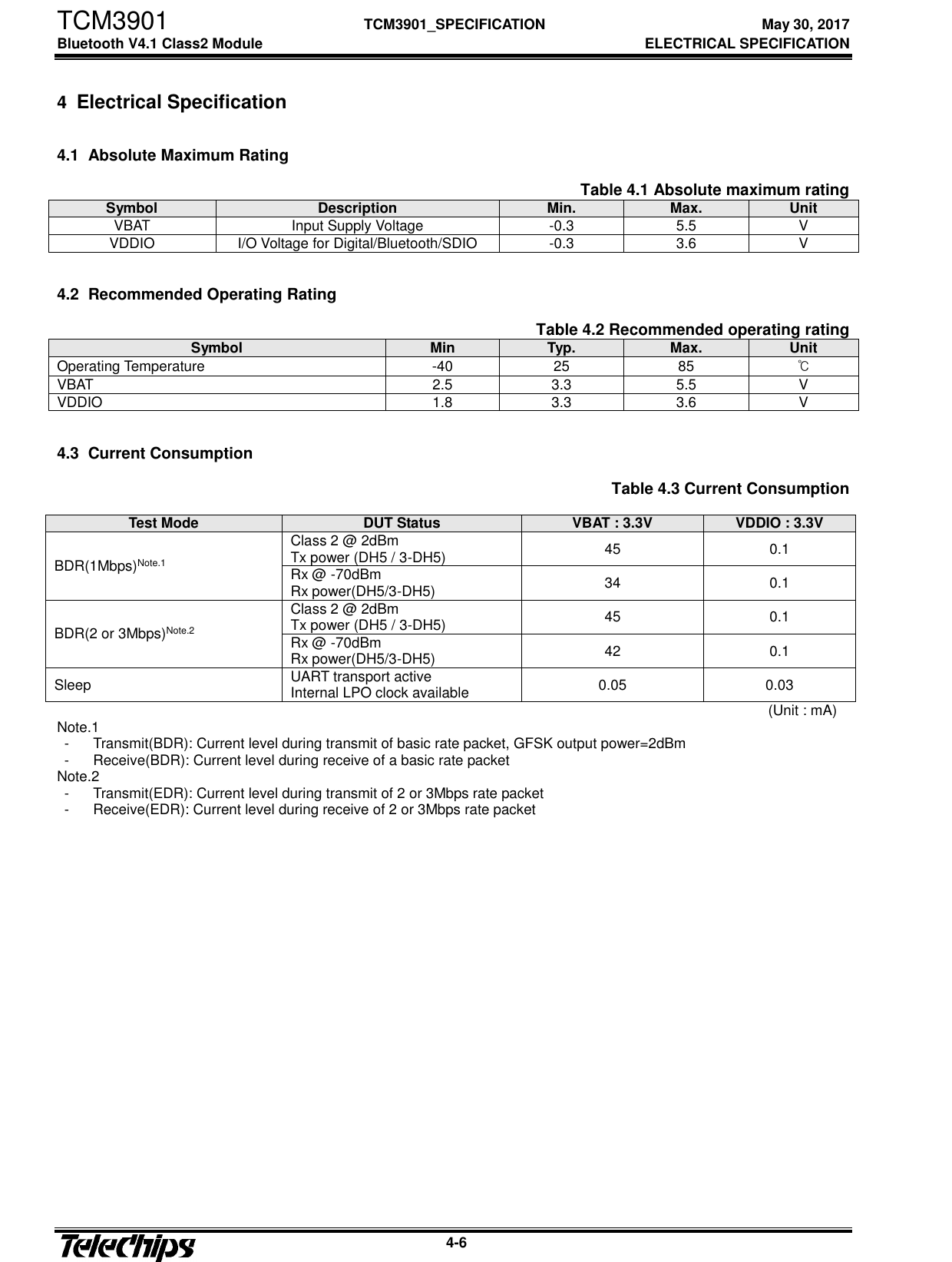
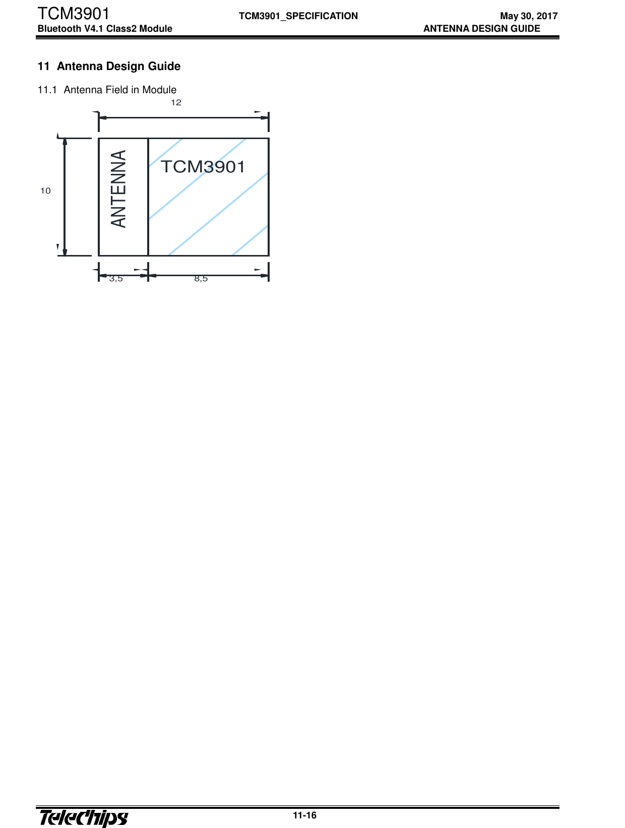
![TCM3901 TCM3901_ SPECIFICATION May 30, 2017 Bluetooth V4.1 Class2 Module RF SPECIFICATION 5-7 5 RF Specification Nomal Condition : 25deg.C, VBAT=3.3V, VDDIO=3.3V Table 0.1 RF Specification Transmitter Min Typ Max Unit BDR Output Power(Class 2) 0 2 4 dBm Frequency range 2401 - 2480 MHz 20dB bandwidth - - 1 MHz Adjacent Channel Power [M-N]=2 - - -20 dBm [M-N]>=3 - - -40 dBm Modulation Characteristics Delta f1avg 140 - 175 KHz Delta f2max (at 99.9%) 99.9 - - % Delta f2avg / Delta f1avg 0.8 - - % Initial Carrier Frequency Tolerance -75 - 75 KHz Carrier Frequency Drift 1slot -25 - 25 KHz 3slot / 5slot -40 - 40 KHz Maximum drift rate -20 - 20 KHz/50uS EDR EDR Relative Power for DQPSK / 8DPSK -4 - 1 dBm EDR Carrier Frequency Stability and Modulation Accuracy wi -75 - 75 KHz wi+wo -75 - 75 KHz wo -10 - 10 KHz RMS DEVM(DQPSK) - - 20 % Peak DEVM(DQPSK) - - 35 % 99% DEVM(DQPSK) 99 - - % RMS DEVM(8DPSK) - - 13 % Peak DEVM(8DPSK) - - 25 % 99% DEVM(8DPSK) 99 - - % Receiver Min Typ Max Unit BDR Sensitivity(BER=<0.1%) for GFSK -70 - - dBm Maximum input Level(BER=<0.1%) -20 - - dBm EDR Sensitivity(BER=<0.007%) for DQPSK -77 - dBm Sensitivity(BER=<0.007%) for 8DPSK -77 - dBm](https://usermanual.wiki/Telechips/3901/User-Guide-3418984-Page-11.png)