Telechips 3901 Bluetooth module User Manual TCM3901 SPECIFICATION
Telechips Bluetooth module TCM3901 SPECIFICATION
User Manual

SPECIFICATION
TCM3901
Bluetooth 4.1 Class2 Module
RF&BB
TCM3901_SPECIFICATION_V0.1.3
Rev. 0.1.3
May 30, 2017

3
DISCLAIMER
All information and data contained in this material are without any commitment, are not to be considered as an offer for
conclusion of a contract, nor shall they be construed as to create any liability. Any new issue of this material invalidates
previous issues. Product availability and delivery are exclusively subject to our respective order confirmation form; the same
applies to orders based on development samples delivered. By this publication, Telechips, Inc. does not assume
responsibility for patent infringements or other rights of third parties that may result from its use.
Further, Telechips, Inc. reserves the right to revise this publication and to make changes to its content, at any time, without
obligation to notify any person or entity of such revisions or changes.
No part of this publication may be reproduced, photocopied, stored on a retrieval system, or transmitted without the express
written consent of Telechips, Inc.
This product is designed for general purpose, and accordingly customer be responsible for all or any of intellectual property
licenses required for actual application. Telechips, Inc. does not provide any indemnification for any intellectual properties
owned by third party.
Telechips, Inc. can not ensure that this application is the proper and sufficient one for any other purposes but the one
explicitly expressed herein. Telechips, Inc. is not responsible for any special, indirect, incidental or consequential damage or
loss whatsoever resulting from the use of this application for other purposes.
COPYRIGHT STATEMENT
Copyright in the material provided by Telechips, Inc. is owned by Telechips unless otherwise noted.
For reproduction or use of Telechips’ copyright material, permission should be sought from Telechips. That permission, if
given, will be subject to conditions that Telechips’ name should be included and interest in the material should be
acknowledged when the material is reproduced or quoted, either in whole or in part. You must not copy, adapt, publish,
distribute or commercialize any contents contained in the material in any manner without the written permission of Telechips.
Trade marks used in Telechips’ copyright material are the property of Telechips.
Important Notice
For customers who use licensed Codec ICs and/or licensed codec firmware of mp3:
“Supply of this product does not convey a license nor imply any right to distribute content created with this product in
revenue-generating broadcast systems (terrestrial. Satellite, cable and/or other distribution channels), streaming
applications(via internet, intranets and/or other networks), other content distribution systems(pay-audio or audio-on-demand
applications and the like) or on physical media(compact discs, digital versatile discs, semiconductor chips, hard drives,
memory cards and the like). An independent license for such use is required. For details, please visit
http://mp3licensing.com”.
For customers who use other firmware of mp3:
“Supply of this product does not convey a license under the relevant intellectual property of Thomson and/or Fraunhofer
Gesellschaft nor imply any right to use this product in any finished end user or ready-to-use final product. An independent
license for such use is required. For details, please visit http://mp3licensing.com”.
For customers who use Digital Wave DRA solution:
“Supply of this implementation of DRA technology does not convey a license nor imply any right to this implementation in
any finished end-user or ready-to-use terminal product. An independent license for such use is required.”
For customers who use DTS technology:
"This product made under license to certain U.S. patents and/or foreign counterparts."
"© 1996 – 2011 DTS, Inc. All rights reserved."
For customers who use Dolby technology:
"Supply of this Implementation of Dolby technology does not convey a license nor imply a right under any patent,
or any other industrial or intellectual property right of Dolby Laboratories, to use this Implementation in any
finished end-user or ready-to-use final product. It is hereby notified that a license for such use is required from
Dolby Laboratories."
For customers who use MS technology:
"This product is subject to certain intellectual property rights of Microsoft and cannot be used or disctributed
further without the appropriate license(s) from Microsoft."
TCM3901 TCM3901_ SPECIFICATION May 30, 2017
Bluetooth V4.1 Class2 Module REVISION HISTORY
5
Revision History
Date
Revision
Description
2017-01-19
0.1.0
Initial release
Bluetooth V4.1 Class 2 Module
2017-01-24
0.1.1
10. Reference Peripheral circuit update
11. Antenna design guide release
2017-04-12
0.1.2
3. Pin description update
4. Electrical Specification update
6.Internal Pattern Antenna Specification
7. Startup Timing update (BT_REG_ON)
10. Reference Peripheral circuit update
11.3. In case of using the internal antenna Delete
11.4 . Reserved External Antenna use Delete
12. SMT Temperature Sequence (Pb-free) updata
2017-05-30
0.1.3
Add features list

TCM3901 TCM3901_ SPECIFICATION May 30, 2017
Bluetooth V4.1 Class2 Module TABLE OF CONTENTS
7
TABLE OF CONTENTS
Contents
1 Introduction ........................................................................................................................................................................ 1-1
2 Features ............................................................................................................................................................................. 2-3
3 Pin description .................................................................................................................................................................... 3-5
3.1 Pin Assignment ........................................................................................................................................................ 3-5
4 Electrical Specification ........................................................................................................................................................ 4-6
4.1 Absolute Maximum Rating........................................................................................................................................ 4-6
4.2 Recommended Operating Rating ............................................................................................................................. 4-6
4.3 Current Consumption ............................................................................................................................................... 4-6
5 RF Specification ................................................................................................................................................................. 5-7
6 Internal Pattern Antenna Specification................................................................................................................................ 6-9
6.1 Antenna Gain ........................................................................................................................................................... 6-9
6.2 Antenna 3D Radiation Pattern .................................................................................................................................. 6-9
7 Startup Timing .................................................................................................................................................................. 7-10
8 Interface Description .........................................................................................................................................................8-11
8.1 UART ......................................................................................................................................................................8-11
8.2 PCM/I2S ..................................................................................................................................................................8-11
8.3 SECI ....................................................................................................................................................................... 8-12
9 Mechanical Information .................................................................................................................................................... 9-13
10 Reference Peripheral Circuit ........................................................................................................................................ 10-15
11 Antenna Design Guide ................................................................................................................................................... 11-16
11.1 Antenna Field in Module ...................................................................................................................................... 11-16
11.2 Module position on Target board ............................................................... 오류! 책갈피가 정의되어 있지 않습니다.
12 SMT Temperature Sequence (Pb-free)......................................................................................................................... 12-17

TCM3901 TCM3901_ SPECIFICATION May 30, 2017
Bluetooth V4.1 Class2 Module FIGURE OF CONTENTS
8
Figures
Figure 1.1 TCM3901 Block Diagram ....................................................................................................................... 1-1
Figure 3.1 Pin Diagram (Top view) .......................................................................................................................... 3-5
Figure 6.1 3D Radiation Pattern .............................................................................................................................. 6-9
Figure 7.1 Startup Timing from RST_N ................................................................................................................. 7-10
Figure 8.1 UART Interface Connection ................................................................................................................. 8-11
Figure 8.2 PCM Interface Connection ................................................................................................................... 8-11
Figure 8.3 SECI Interface Connection ................................................................................................................... 8-12
Figure 9.1 32-pin LGA package Mechanical Information (TOP VIEW) .................................................................. 9-13
Figure 9.2 PCB Footprint recommendation ........................................................................................................... 9-14
Figure 10.1 Reference Peripheral Circuit ............................................................................................................ 10-15
Figure 12.1 SMT Temperature Sequence ........................................................................................................... 12-17

TCM3901 TCM3901_ SPECIFICATION May 30, 2017
Bluetooth V4.1 Class2 Module TABLE OF CONTENTS
9
Tables
Table 3.1 Pin Description ........................................................................................................................................ 3-5
Table 4.1 Absolute maximum rating ........................................................................................................................ 4-6
Table 4.2 Recommended operating rating .............................................................................................................. 4-6
Table 4.3 Current Consumption .............................................................................................................................. 4-6
Table 5.1 RF Specification ...................................................................................................................................... 5-7
Table 6.1 Antenna Gain ........................................................................................................................................... 6-9
TCM3901 TCM3901_ SPECIFICATION May 30, 2017
Bluetooth V4.1 Class2 Module INTRODUCTION
1-1
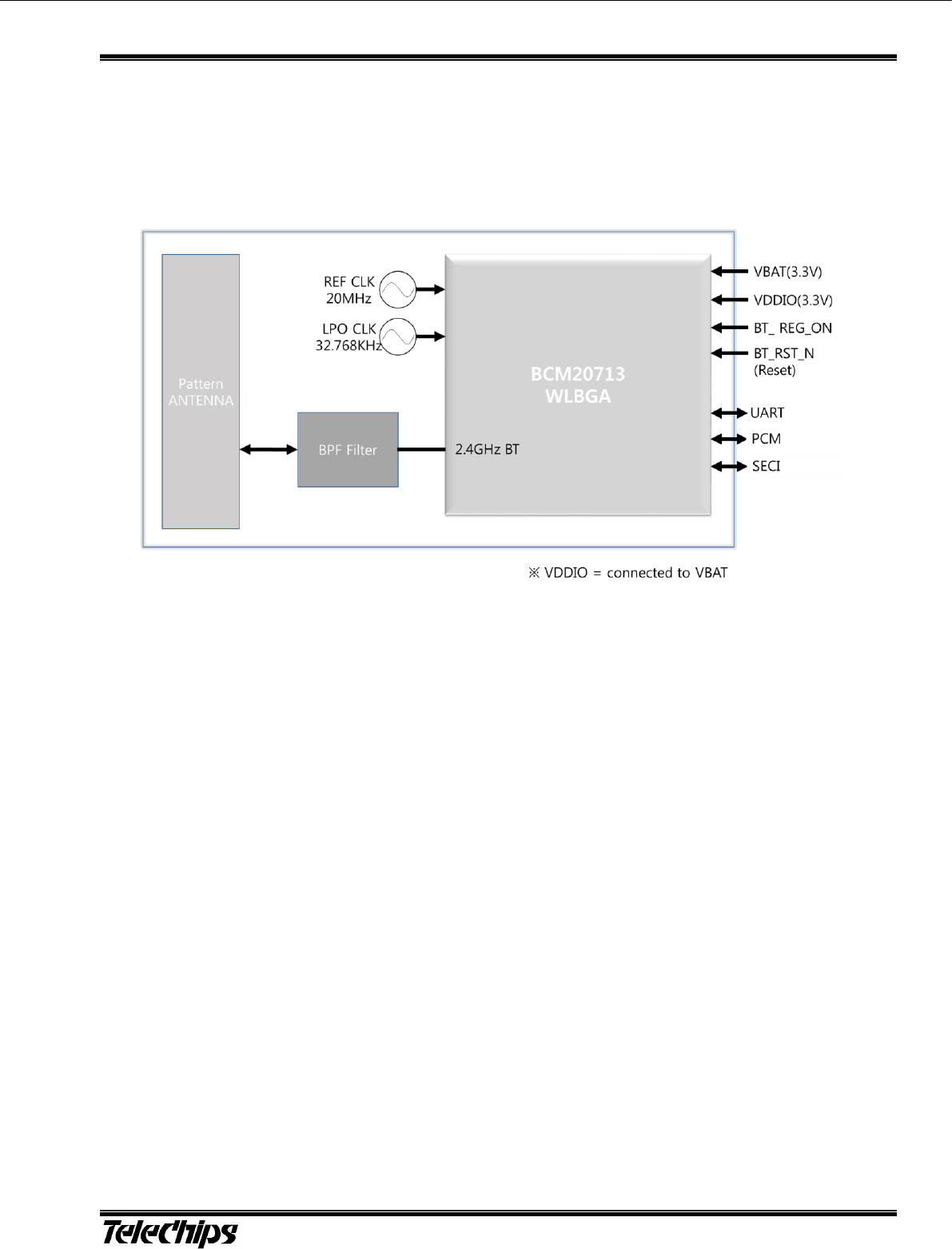
1 Introduction
The TCM3901 is the optimal solution for voice and data applications that require a Bluetooth SIG standard Host Controller
Interface(HCI) via UART and PCM/I2S audio interface support.
In addition, the serial enhanced coexistence interface is available for WLAN devices.
This module has adopted BCM20713 industrial WLBGA chipset.
Figure 1.1 TCM3901 Block Diagram

TCM3901 TCM3901_ SPECIFICATION May 30, 2017
Bluetooth V4.1 Class2 Module FEATURES
2-3
2 Features
Bluetooth 4.1 + EDR compliant
Bluetooth Low Energy
Programmable output power control meets Class1, Class2.
High speed UART port(Up to 4Mbps)
PCM/I2S digital audio interface
Enhanced Coexistence Interface with 3-wire(SECI_OUT, SECI_IN, BT_STATUS)
Supports Broadcom SmartAudio, wide-band speech, SBC codec and pccket loss concealment.
Use supply voltage up to 5.5V
Ultra-low power consumption
Built-in PCB pattern antenna
Built-in 32.768KHz LPO clock oscillator
Operating temperature range(-40℃ ~+85℃)
Competitive size (12mm x 10mm x 1.9T : LGA 32-pin)
TCM3901 TCM3901_ SPECIFICATION May 30, 2017
Bluetooth V4.1 Class2 Module PIN DESCRIPTION
3-5
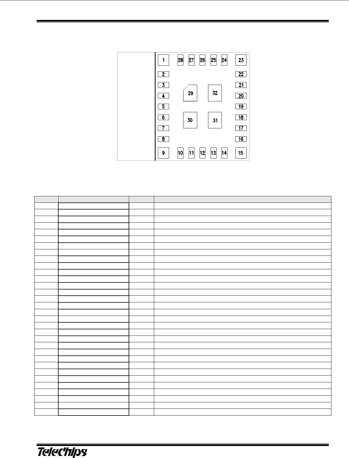
3 Pin description
3.1 Pin Assignment
Figure 3.1 Pin Diagram (Top view)
Table 3.1 Pin Description
No.
Name
Type
Description
1
GND
GND
Ground connection
2
VDDIO_3V3
P
I/O voltage supply input
3
Reserved(LPO)
I
Reserved external LPO (32.768KHz)1)
4
GND
GND
Ground connection
5
GND
GND
Ground connection
6
GND
GND
Ground connection
7
GND
GND
Ground connection
8
GND
GND
Ground connection
9
ANT
I/O
Internal Antenna port
10
Reserved(RF)
I/O
RF In / Out port2)
11
GND
GND
Ground connection
12
VBAT_3V3
P
Main power voltage source input
13
BT_RST_N
I
Active-low reset input. Requires an external 10Kohm pull-up resistor
14
BT_REG_ON
I
Internal Regulator – High : ON / Low : OFF
15
GND
GND
Ground connection
16
UART_TX
O
UART transmit data
17
UART_RX
I
UART receive data
18
UART_RTS
O
UART request to send output
19
UART_CTS
I
UART clear to send input
20
SECI_OUT
O
SECI output
21
SECI_IN
I
SECI input
22
GPIO_0
I/O
Rerserved GPIO
23
GND
GND
Ground connection
24
BT_STATUS
O
BT status
25
PCM_OUT
O
PCM data out
26
PCM_IN
I
PCM data in
27
PCM_CLK
I/O
PCM clock
28
PCM_SYNC
I/O
PCM sync signal
29
GND
GND
Ground connection
30
GND
GND
Ground connection
31
GND
GND
Ground connection
32
GND
GND
Ground connection
1) Pin.3 Reserved(External LPO) : This pin is not used because there is an internal LPO.
2) Pin.10 Reserved(RF) : This pin is not used because there is an internal matching.
3) All digital I/O has internal pull-up or pull-down values which are around 60Kohm
TCM3901 TCM3901_SPECIFICATION May 30, 2017
Bluetooth V4.1 Class2 Module ELECTRICAL SPECIFICATION
4-6
4 Electrical Specification
4.1 Absolute Maximum Rating
Table 4.1 Absolute maximum rating
Symbol
Description
Min.
Max.
Unit
VBAT
Input Supply Voltage
-0.3
5.5
V
VDDIO
I/O Voltage for Digital/Bluetooth/SDIO
-0.3
3.6
V
4.2 Recommended Operating Rating
Table 4.2 Recommended operating rating
Symbol
Min
Typ.
Max.
Unit
Operating Temperature
-40
25
85
℃
VBAT
2.5
3.3
5.5
V
VDDIO
1.8
3.3
3.6
V
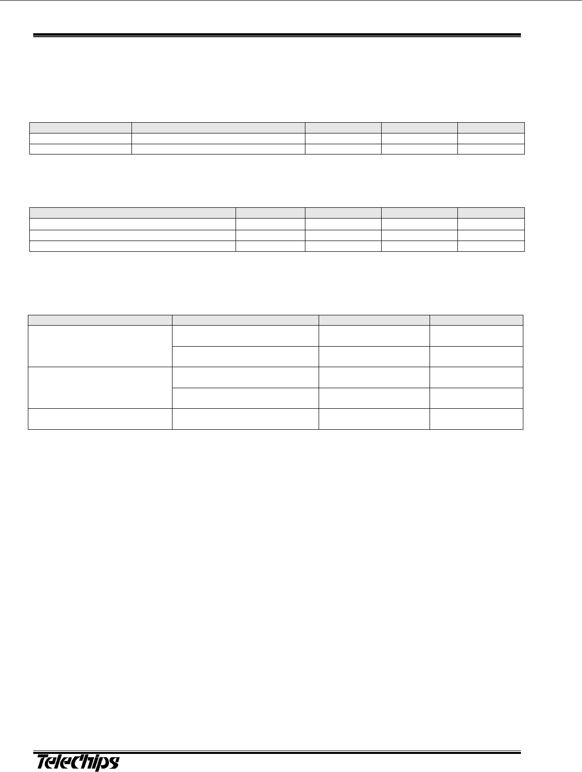
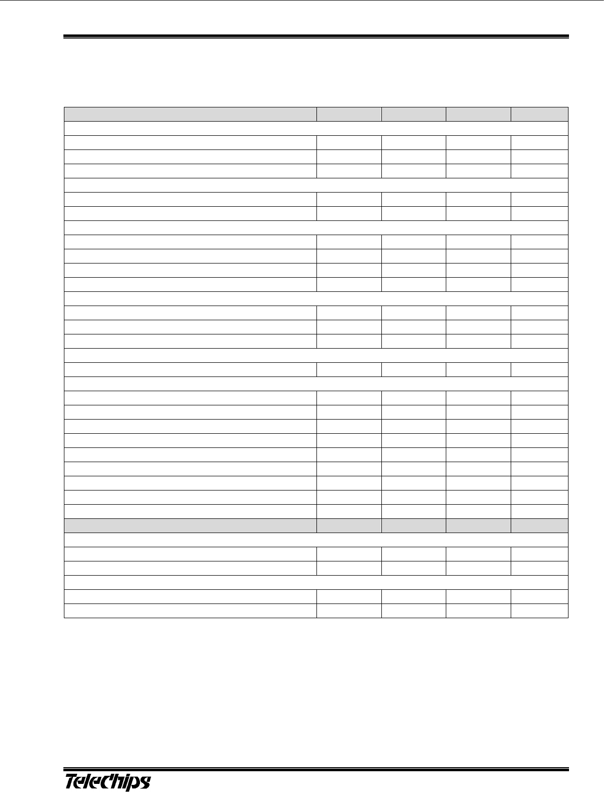
4.3 Current Consumption
Table 4.3 Current Consumption
Test Mode
DUT Status
VBAT : 3.3V
VDDIO : 3.3V
BDR(1Mbps)Note.1
Class 2 @ 2dBm
Tx power (DH5 / 3-DH5)
45
0.1
Rx @ -70dBm
Rx power(DH5/3-DH5)
34
0.1
BDR(2 or 3Mbps)Note.2
Class 2 @ 2dBm
Tx power (DH5 / 3-DH5)
45
0.1
Rx @ -70dBm
Rx power(DH5/3-DH5)
42
0.1
Sleep
UART transport active
Internal LPO clock available
0.05
0.03
(Unit : mA)
Note.1
- Transmit(BDR): Current level during transmit of basic rate packet, GFSK output power=2dBm
- Receive(BDR): Current level during receive of a basic rate packet
Note.2
- Transmit(EDR): Current level during transmit of 2 or 3Mbps rate packet
- Receive(EDR): Current level during receive of 2 or 3Mbps rate packet
TCM3901 TCM3901_ SPECIFICATION May 30, 2017
Bluetooth V4.1 Class2 Module RF SPECIFICATION
5-7
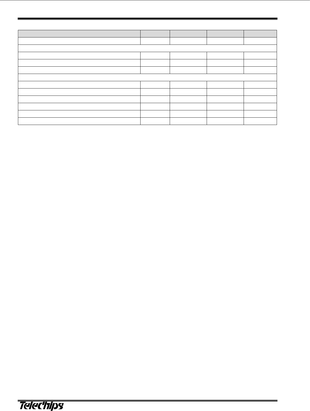
5 RF Specification
Nomal Condition : 25deg.C, VBAT=3.3V, VDDIO=3.3V Table 0.1 RF Specification
Transmitter
Min
Typ
Max
Unit
BDR
Output Power(Class 2)
0
2
4
dBm
Frequency range
2401
-
2480
MHz
20dB bandwidth
-
-
1
MHz
Adjacent Channel Power
[M-N]=2
-
-
-20
dBm
[M-N]>=3
-
-
-40
dBm
Modulation Characteristics
Delta f1avg
140
-
175
KHz
Delta f2max (at 99.9%)
99.9
-
-
%
Delta f2avg / Delta f1avg
0.8
-
-
%
Initial Carrier Frequency Tolerance
-75
-
75
KHz
Carrier Frequency Drift
1slot
-25
-
25
KHz
3slot / 5slot
-40
-
40
KHz
Maximum drift rate
-20
-
20
KHz/50uS
EDR
EDR Relative Power for DQPSK / 8DPSK
-4
-
1
dBm
EDR Carrier Frequency Stability and Modulation Accuracy
wi
-75
-
75
KHz
wi+wo
-75
-
75
KHz
wo
-10
-
10
KHz
RMS DEVM(DQPSK)
-
-
20
%
Peak DEVM(DQPSK)
-
-
35
%
99% DEVM(DQPSK)
99
-
-
%
RMS DEVM(8DPSK)
-
-
13
%
Peak DEVM(8DPSK)
-
-
25
%
99% DEVM(8DPSK)
99
-
-
%
Receiver
Min
Typ
Max
Unit
BDR
Sensitivity(BER=<0.1%) for GFSK
-70
-
-
dBm
Maximum input Level(BER=<0.1%)
-20
-
-
dBm
EDR
Sensitivity(BER=<0.007%) for DQPSK
-77
-
dBm
Sensitivity(BER=<0.007%) for 8DPSK
-77
-
dBm
TCM3901 TCM3901_SPECIFICATION May 30, 2017
Bluetooth V4.1 Class2 Module
5-8
Bluetooth LE(Low Energy)
Min
Typ
Max
Unit
Output Power
-
-
10
dBm
Modulation Characteristics
Delta f1avg
225
-
275
KHz
Delta f2max (at 99.9%)
99
-
-
%
Delta f2avg / Delta f1avg
0.8
-
-
%
Carrier Frequency Offset and Drift
Frequency Offset
-
-
150
KHz
Frequency Drift
-
-
50
KHz
Drift Rate
-
-
20
KHz
Receiver Sensitivity(PER<30.8%)
-70
-
-
dBm
Maximum Input Signal Level(PER<30.8%)
-10
-
-
dBm
PER Report Integrity (-30dBm Input)
50
-
65.4
%
TCM3901 TCM3901_ SPECIFICATION May 30, 2017
Bluetooth V4.1 Class2 Module INTERNAL PATTERN ANTENNA SPECIFICATION
6-9
6 Internal Pattern Antenna Specification
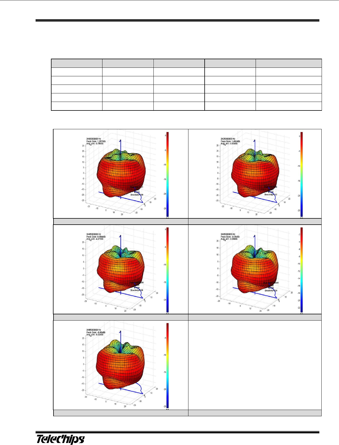
6.1 Antenna Gain Table 6.1 Antenna Gain
Frequency
Efficiency
Average Gain
Max Gain
Max Position
2400MHz
41.8 %
-3.8 dBi
1.2 dBi
Theta105/Pie60
2425MHz
43.1 %
-3.7 dBi
1.5 dBi
Theta105/Pie60
2445MHz
35.7 %
-4.5 dBi
0.6 dBi
Theta105/Pie60
2465MHz
31.0 %
-5.1 dBi
-0.1 dBi
Theta105/Pie60
2485MHz
27.4 %
-5.6 dBi
-0.7 dBi
Theta105/Pie240
6.2 Antenna 3D Radiation Pattern
2400MHz Pattern
2425MHz Pattern
2445MHz Pattern
2465MHz Pattern
2485MHz Pattern
Figure 6.1 3D Radiation Pattern
TCM3901 TCM3901_SPECIFICATION May 30, 2017
Bluetooth V4.1 Class2 Module STARTUP TIMING
7-10
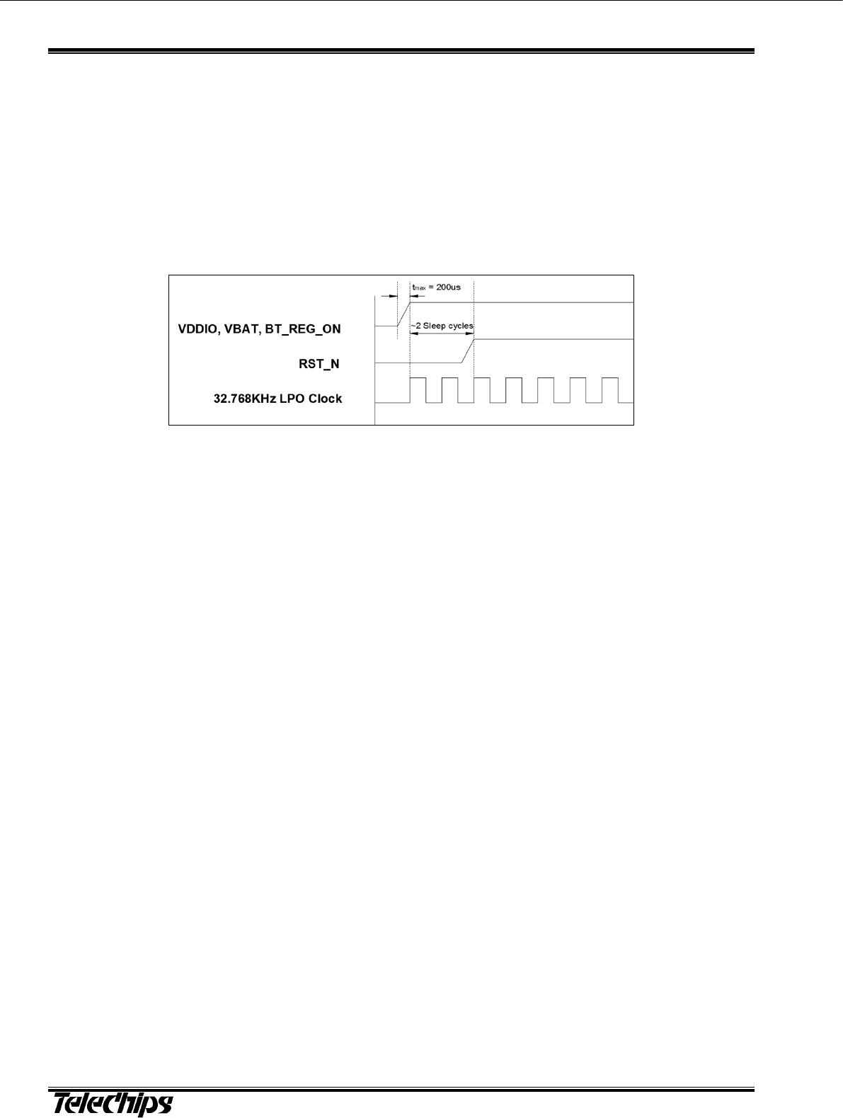
7 Startup Timing
The TCM3901 startup and firmware boot is held off while the RESET pin is asserted.
The TCM3901 has an integrated power-on reset circuit which completely resets all circuits to a known power on state. This
action can also be driven by RST_N signal, which can be used to externally control the device, forcing it into a power-on
reset state.
Note:
VBAT should be up before or at the same time as VDDIO, BT_REG_ON.
RST_N signal input is an active-low signal. This signal must be driven high or low (not left floating).
The TCM3901 requires an external pull-up resistor on the RST_N input.
Figure 7.1 Startup Timing from RST_N
TCM3901 TCM3901_ SPECIFICATION May 30, 2017
Bluetooth V4.1 Class2 Module INTERFACE DESCRIPTION
8-11
8 Interface Description
8.1 UART
The UART physical interface is a standard, 4-wire(RX, TX, RTS, CTS) with adjustable baud rates from 9600 bps to 4.0 Mbps.
The interface features an automatic baud rate detection capability that returns a baud rate selection. Alternatively, the baud
rate can be selected via a vendor-specific UART HCI commend. The interface supports Bluetooth UART HCI specifications.
The default baud rate is 115.2Kbaud.
Figure 8.1 UART Interface Connection
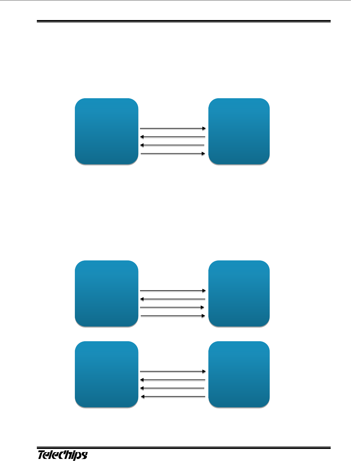
8.2 PCM/I2S
The TCM3901 PCM interface can connect to linear PCM codec devices in master or slave mode. In master mode, the
device generates the PCM_BCLK and PCM_SYNC signals. In slave mode, these signals are provided by another master on
the PCM interfaces as inputs to the device.
The PCM interface supports the industry standard formats for I2S, left-justified or right-justified.
The host can adjust the PCM interface configuration using vendor-specific HCI commands or it can be setup in the
configuration file.
Figure 8.2 PCM Interface Connection
TCM3901
(Master)
PCM_OUT
PCM_IN
PCM_BCLK
PCM_SYNC
PCM_IN
PCM_OUT
PCM_BCLK
PCM_SYNC
Codec
(Slave)
TCM3901
(Slave)
PCM_OUT
PCM_IN
PCM_BCLK
PCM_SYNC
PCM_IN
PCM_OUT
PCM_BCLK
PCM_SYNC
Codec
(Master)
HOST
TCM3901
HOST_TX
HOST_RX
HOST_CTS
HOST_RTS
UART_RX
UART_TX
UART_RTS
UART_CTS
TCM3901 TCM3901_SPECIFICATION May 30, 2017
Bluetooth V4.1 Class2 Module INTERFACE DESCRIPTION
8-12
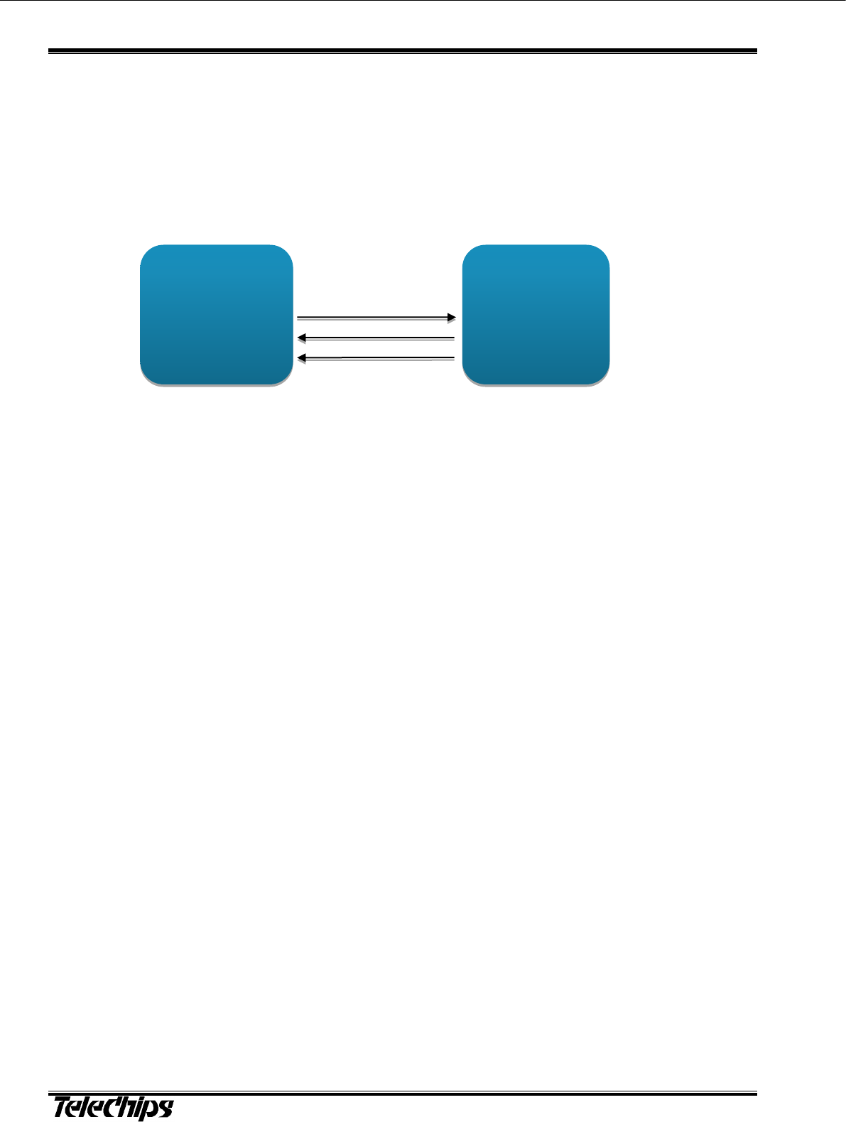
8.3 SECI
The TCM3901 provides extensions and collaborative coexistence to the standard Bluetooth AFH for direct communication
with WLAN devices. Collaborative coexistence enables WLAN and Bluetooth to operate simultaneously in a single device.
The device supports industry-standard coexistence signaling, including 802.15.2, and supports WLAN solutions.
Enhanced coexistence data can be exchanged over SECI_IN and SECI_OUT
It supports generic UART communication between WLAN and Bluetooth devices.
Up to 48-bits of coexistence data can bel exchanged
Figure 8.3 SECI Interface Connection
TCM3901
SECI_OUT
SECI_IN
BT_STATUS
SECI_IN
SECI_OUT
BT_STATUS
WLAN
device
TCM3901 TCM3901_ SPECIFICATION May 30, 2017
Bluetooth V4.1 Class2 Module MECHANICAL INFORMATION
9-13
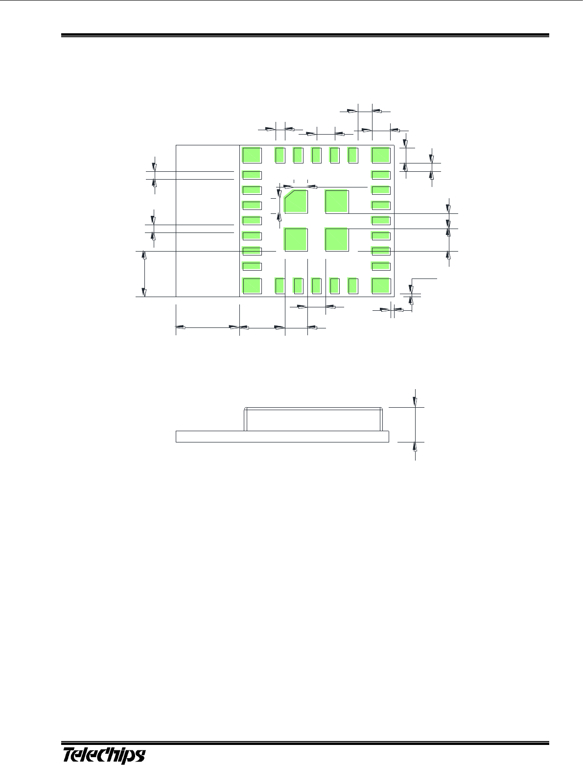
9 Mechanical Information
(Unit : mm)
0,5
1
1
0,8
1
0,55
0,2
0,2
1
3
2,5
3,5
1
1,25
1,5
0,5
0,5
0,75
1
Figure 9.1 32-pin LGA package Mechanical Information (TOP VIEW)
1,9
Figure 9.1 Side View

TCM3901 TCM3901_SPECIFICATION May 30, 2017
Bluetooth V4.1 Class2 Module MECHANICAL INFORMATION
9-14
0,5
1,2
1,2
0,8
1
0,55
1
3
2,5
3,5
1
1,25
1,5
0,5
0,5
0,75
1
11
30
Copper cut out area
12
10
※ Antenna part should be placed outside the PCB
Figure 9.2 PCB Footprint recommendation
TCM3901 TCM3901_ SPECIFICATION May 30, 2017
Bluetooth V4.1 Class2 Module REFERENCE PERIPHERAL CIRCUIT
10-15
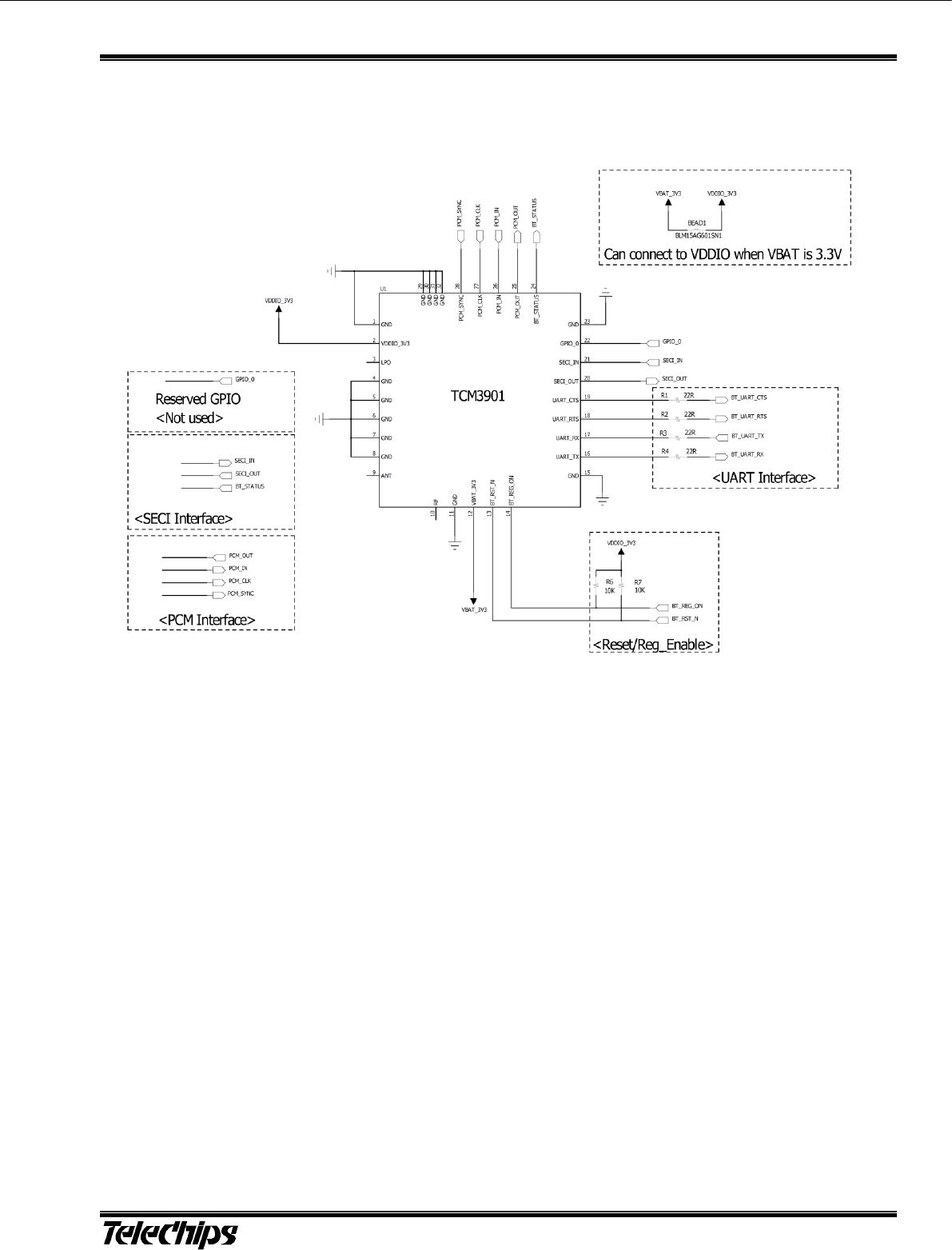
10 Reference Peripheral Circuit
Figure 0.1 Reference Peripheral Circuit
TCM3901 TCM3901_SPECIFICATION May 30, 2017
Bluetooth V4.1 Class2 Module ANTENNA DESIGN GUIDE
11-16
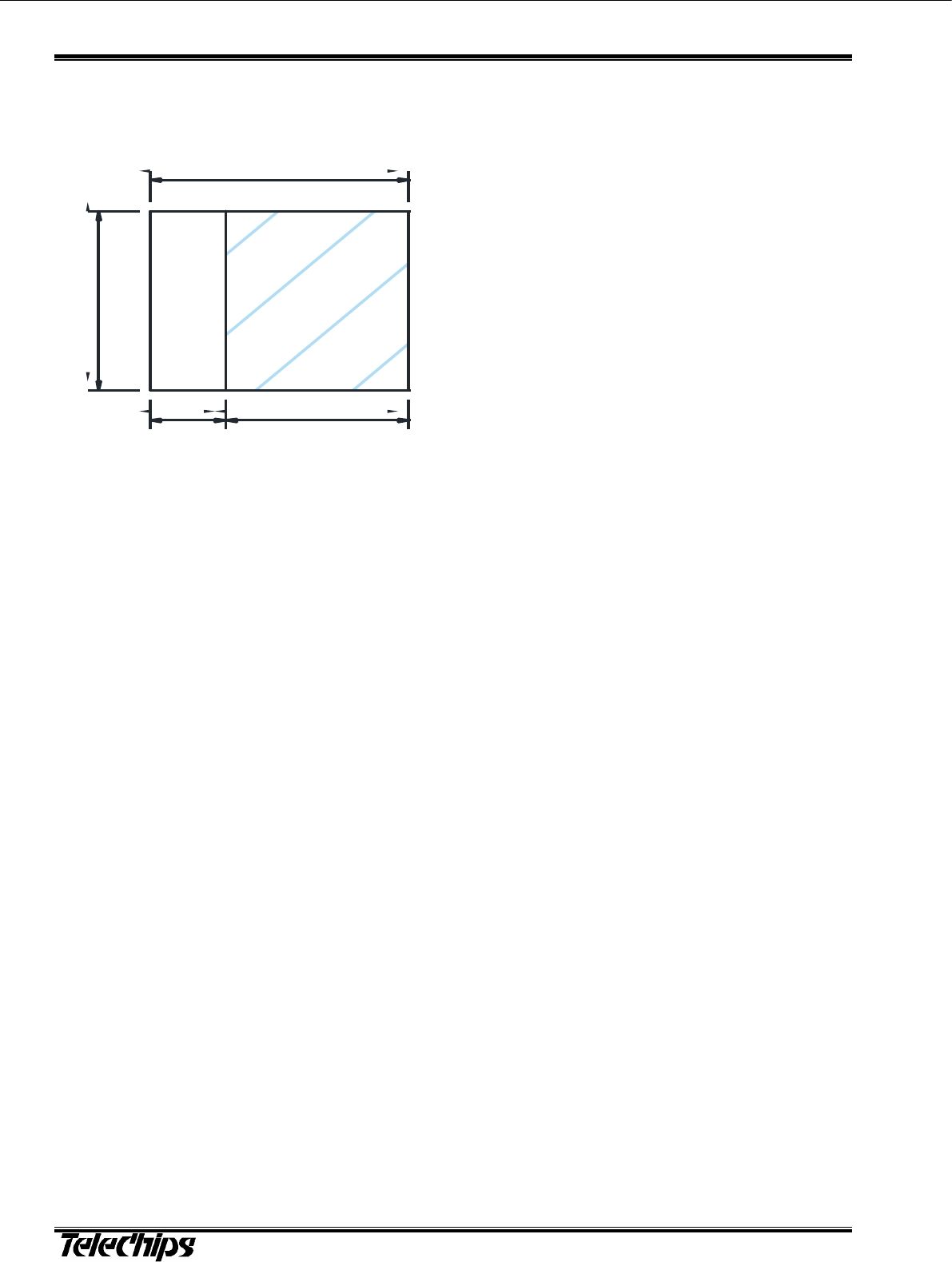
11 Antenna Design Guide
11.1 Antenna Field in Module
12
10
3,5 8,5
ANTENNA
TCM3901
TCM3901 TCM3901_ SPECIFICATION May 30, 2017
Bluetooth V4.1 Class2 Module SMT TEMPERATURE SEQUENCE (PB-FREE)
12-17
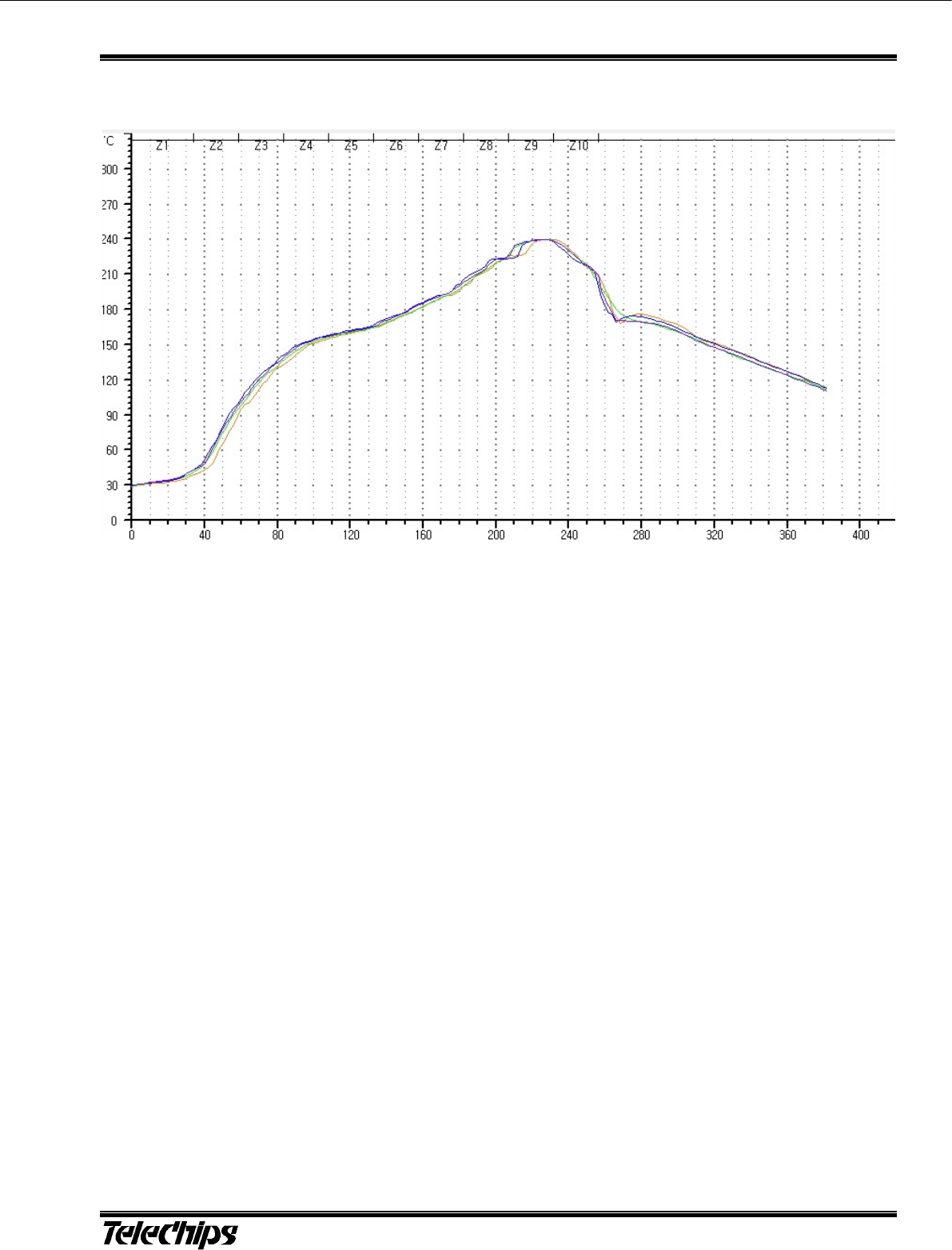
12 SMT Temperature Sequence (Pb-free)
Figure 12.1 SMT Temperature Sequence

TCM3901 TCM3901_SPECIFICATION May 30, 2017
Bluetooth V4.1 Class2 Module SMT TEMPERATURE
SEQUENCE (PB-FREE)
12-18
Certifications
Certified under FCC Part 15
Certified in Canada by IC to RSS-247
Manufacturer Model : TCM3901
FCC ID: 2ALS3-3901
IC: 22661-3901
Product Marketing Name (PMN): Bluetooth module
FCC Statement
This device complies with Part 15 of the FCC rules. Operation is subject to the following conditions: ( 1 )This device may not
cause harmful interference, and (2) This device must accept any interference received, including
interference that may cause undesired operation.
FCC Caution
Any changes or modifications not expressly approved by the party responsible for compliance could void the user's authority
to operate this equipment.
Important Note
OEM Responsibilities to comply with FCC and Industry Canada Regulations
The TCM3901 Module has been certified for integration into products only by OEM integrators under the following
conditions:
1. The antenna(s) must be installed such that a minimum separation distance of 20cm is maintained
between the radiator (antenna) and all persons at all times.
2. The transmitter module must not be co-located or operating in conjunction with any other antenna or
transmitter.
As long as the two conditions above are met, further transmitter testing will not be required. However, the OEM
integrator is still responsible for testing their end-product for any additional compliance requirements required with this
module installed (for example, digital device emissions, PC peripheral requirements, etc.).
IMPORTANT NOTE: In the event that these conditions cannot be met (for certain configurations or
co-location with another transmitter), then the FCC and Industry Canada authorizations are no longer considered valid
and the FCC ID and IC Certification Number cannot be used on the final product. In these circumstances, the OEM
integrator will be responsible for re-evaluating the end product (including the transmitter) and obtaining a separate
FCC and Industry Canada authorization.
Label of the end product
The final end product must be labeled in a visible area with the following " Contains FCC ID: 2ALS3-3901" and " Contains
IC: 22661-3901". If the size of the end product is larger than 8x10cm, then the following FCC part 15.19 statement has to
also be available on the label: This device complies with Part 15 of FCC rules. Operation is subject to the following two
conditions: (1) this device may not cause harmful interference and (2) this device must accept any interference received,
including interference that may cause undesired operation.
Canada Statement
“This device complies with Industry Canada’s license-exempt RSSs.
Operation is subject to the following two conditions:
(1) This device may not cause interference; and
(2) This device must accept any interference,
including interference that may cause undesired operation of the device.”
« Le présent appareil est conforme aux CNR d'Industrie Canada applicables
aux appareils radio exempts de licence. L'exploitation est autorisée aux
deux conditions suivantes : (1) l'appareil ne doit pas produire de brouillage,
et (2) l'utilisateur de l'appareil doit accepter tout brouillage radioélectrique subi,
même si le brouillage est susceptible d'en compromettre le fonctionnement. »
Exposure to Radio Frequency Energy
“To comply with FCC and Industry Canada RF radiation exposure limits for general population, the antenna(s) used for this
transmitter must be installed such that a minimum separation distance of 20cm is maintained between the radiator (antenna)
and all persons at all times and must not be co-located or operating in conjunction with any other antenna or transmitter.”