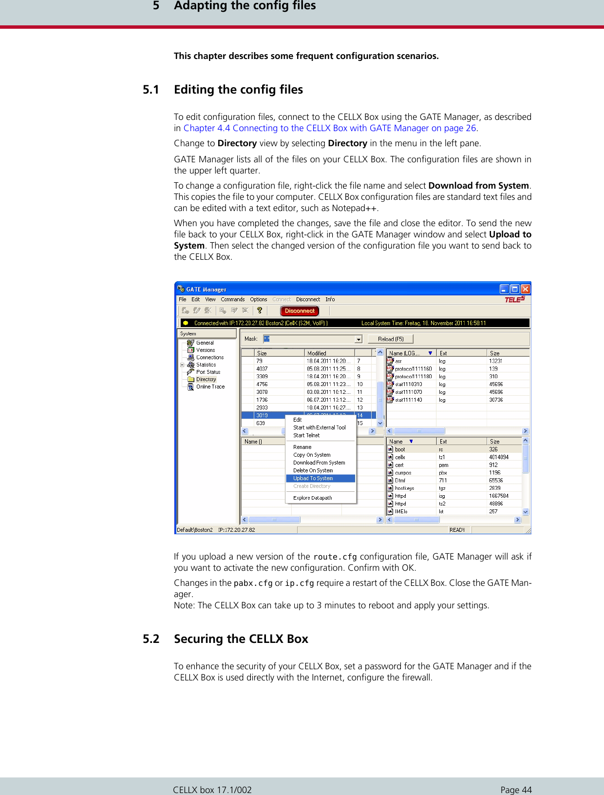
Teles Informationstechnologien GSM04VOIPUS Mobile Gateway User Manual CELLX Box
Teles AG Informationstechnologien Mobile Gateway CELLX Box
UserManual.wiki
>
Teles Informationstechnologien
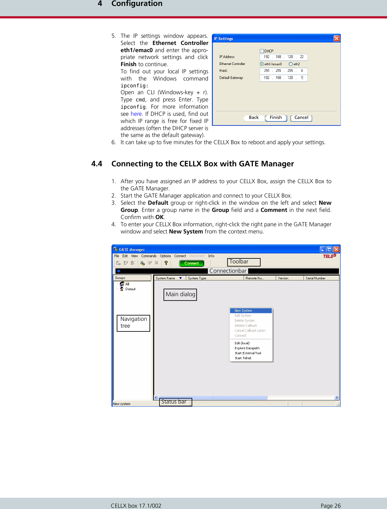
>
GSM04VOIPUS User Manual
Users manual
Navigation menu
Upload a User Manual
Namespaces
Wiki Guide
HTML
PDF
Info
Views
User Manual
Discussion / Help
Navigation

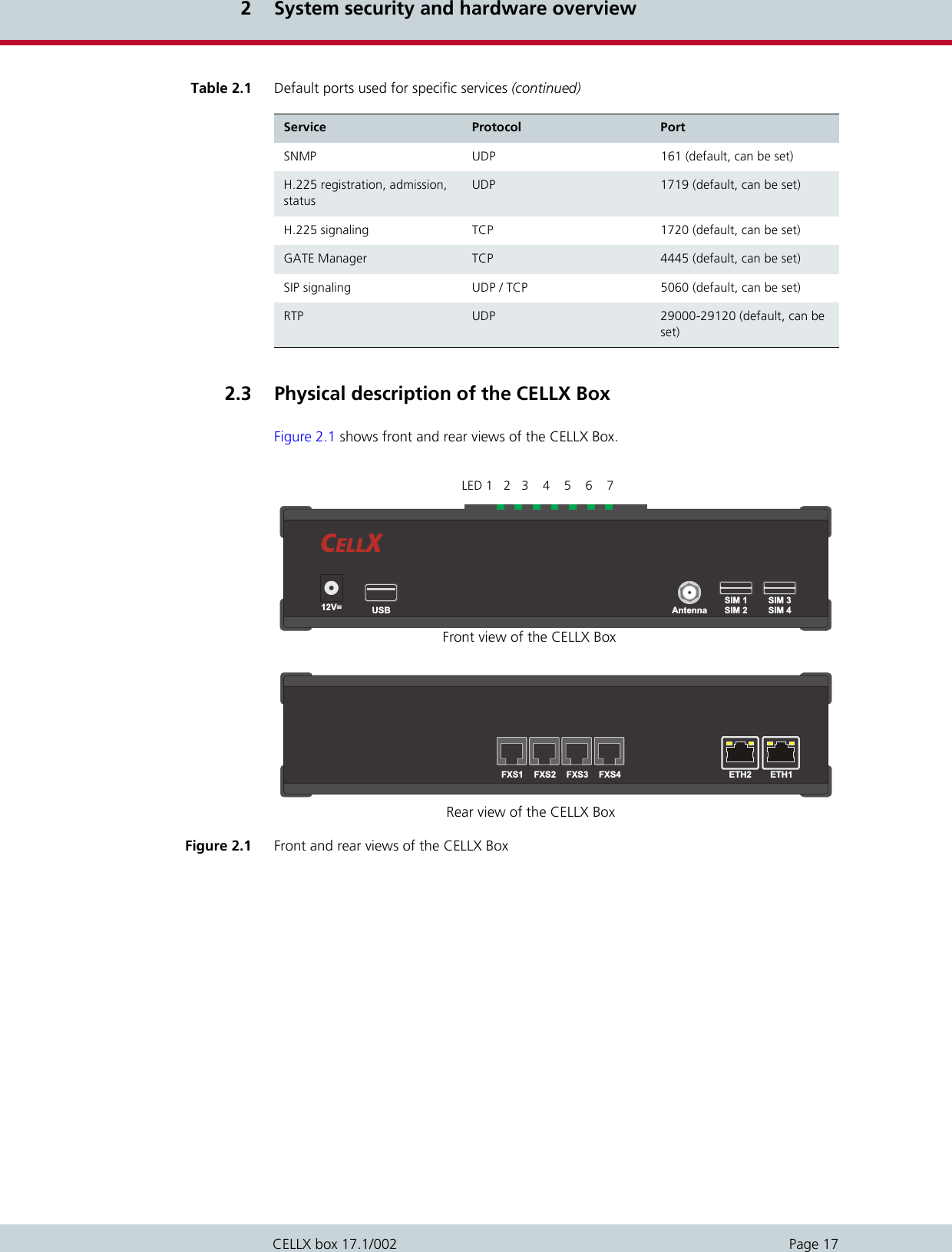

![4 ConfigurationPage 30CELLX box 17.1/0024. Transfer the new configuration file to the CELLX Box and activate the new configura-tion. Changes in the ip.cfg and pabx.cfg require a restart of the CELLX Box. The configuration files are divided into sections. These sections always begin with a line entryin square brackets. The basic required sections are listed in Table 4.3. Comments included in these configuration files must begin with a semicolon. Comments canalso be placed at the end of the code line. Configuration files must end with an empty line.Every section contains one or more expressions. In a expression, a keyword or value is as-signed to a variable. Then, additional options are possible. An equal sign without spaces isplaced between keyword and variable. As shown in Example 4.1: the section is [System], the expression is “PABXName=CELLX-4S_FXS-4“, the variable in the expression is PABXName, the value is “CELLX-4S_FXS-4“, the rest “(1)“ of the line after the semicolon is a comment. 4.6.1 The pabx.cfg config fileThe pabx.cfg file contains the definition of the controller which is needed for routing, and thelocation of the log files needed for maintenance. Only some small changes are needed in this file: change the remote password and if necessary DNS, and NTP adjustments, andSMTP configuration. Table 4.3 Required configuration file sectionsSection In config file Description[System] pabx.cfg route.cfg ip.cfg Every config file must be started with this section. All previ-ous before will ignored. This section contains the system’s basic settings. [eth1] ip.cfg This section contains the IP configuration for the first Ether-net interface.[iptables] ip.cfg This section contains the firewall settings. [Voip:<id>] route.cfg This section contains the VoIP profile. [Registrar:<id>] route.cfg This section contains the registrar profile used in the VoIP profile. Example 4.1 The first part of the pabx.cfg[System]PABXName=CELLX-4S_FXS-4 ;(1)](https://usermanual.wiki/Teles-Informationstechnologien/GSM04VOIPUS/User-Guide-2293360-Page-30.png)
![4 ConfigurationPage 31CELLX box 17.1/002Example 4.2 shows a pabx.cfg file for the last mile scenario. More information about the pabx.cfg is contained in the Chapter 5.2 on page 44 ff. aboutthe configuration. Example 4.2 pabx.cfg for the last mile scenario [System]PABXName=CELLX_GSM-4_FXS-4 ; (1)NameServer=8.8.8.8 ; (2)NtpServer=pool.ntp.orgTimezone=CET-1CEST-2,M3.5.0/02:00:00,M10.5.0/03:00:00 ; Central European TimeActionLog=/boot/protocol.log weekly 1200 3TraceLog=/boot/trace.log daily 900 7MsgLog=/boot/msg.log weekly 1200 3Failedlog=/boot/failed.log daily 1200 7Log=/boot/cdr.log daily 1200 7 ; (3)StatisticTime=/boot/asr.log 00:00 11111111Controller00=10 FXS ; (4)Controller01=11 FXSController02=12 FXSController03=13 FXSController04=20 GSM ; (5)Controller05=21 GSMController06=22 GSMController07=23 GSMController08=40 VOIP ; (6)Controller09=41 DTMFSubscriber00=TRANSPARENT ROUTER ANA[0,16,800,250,1500,80,12800,1,1,500,10500,10000,0,1000] NODE[0000] ; (7)Subscriber01=TRANSPARENT ROUTER ANA[0,16,800,250,1500,80,12800,1,1,500,10500,10000,0,1000] NODE[0001]Subscriber02=TRANSPARENT ROUTER ANA[0,16,800,250,1500,80,12800,1,1,500,10500,10000,0,1000] NODE[0002]Subscriber03=TRANSPARENT ROUTER ANA[0,16,800,250,1500,80,12800,1,1,500,10500,10000,0,1000] NODE[0003]Subscriber04=TRANSPARENT ROUTER GSM[0000,00000,+000000,1,1,1,SIM4,IMSI,BAND(6),TRACE(fecc)] ALARM NODE[0004]Subscriber05=TRANSPARENT ROUTER GSM[0000,00000,+000000,1,1,1,SIM4,IMSI,BAND(6),TRACE(fecc)] ALARM NODE[0005]Subscriber06=TRANSPARENT ROUTER GSM[0000,00000,+000000,1,1,1,SIM4,IMSI,BAND(6),TRACE(fecc)] ALARM NODE[0006]Subscriber07=TRANSPARENT ROUTER GSM[0000,00000,+000000,1,1,1,SIM4,IMSI,BAND(6),TRACE(fecc)] ALARM NODE[0007]Subscriber08=TRANSPARENT ROUTER ALARM CHMAX[8] NODE[0008]Subscriber09=TRANSPARENT ROUTER CHMAX[4] DTMF[60] NODE[0009]#SimCtrlUnitAddress=;*END CONFIG*(1) Definition of the CELLX Box name. This name is displayed in the GATE Manager.(2) DNS and NTP settings of the CELLX Box. Adjust these settings to suit your needs. (3) Path to the call detail records (CDR).(4) Definition of the FXS controller. The controller numbers (10 … 13) are needed for the routing.(5) Definition of the mobile controller. The controller number (20 … 23) are needed for the rout-ing. (6) Definition of the VoIP controller for all VoIP channel. The controller number (40) is needed for the routing. (7) Definition of the settings for FXS controller.](https://usermanual.wiki/Teles-Informationstechnologien/GSM04VOIPUS/User-Guide-2293360-Page-31.png)
![4 ConfigurationPage 32CELLX box 17.1/0024.6.2 The ip.cfg config fileThis file contains the main part of the IP configuration of the CELLX Box. Example 4.3 showsan ip.cfg similar to the factory settings. Only the default gateway and the IP address of thefirst Ethernet interface is set here. These settings are already done during the installation withthe Quickstart tool. The firewall rules are commented out. If the CELLX Box is used behind afirewall in a local network the firewall on the CELLX Box is not needed. Example 4.4 shows the configuration part of the ip.cfg used to configure a default gatewaywith the IP address 192.168.1.1, and an additional route is set fro the network 10.1.2.0/16using the gateway 172.20.17.125 over eth2. The IP address of the second IP interface is setto 172.20.27.224 with the netmaks 255.255.0.0. The section [dnsmasq] shown in Example 4.5 shows an DHCP setup for eth1. All DHCP re-quests will be answered and the CELLX Box assign an IP address form the range 192.168.1.10until 192.168.1.90. The default gateway is the CELLX Box on the eth1 interface and the DNSsettings from the file /etc/resolv.conf will be assigned as name server to the hosts. Example 4.3 ip.cfg with default gateway and IP address set [System]DefaultGW=192.168.1.1[eth1]IpAddress=192.168.1.2 netmask 255.255.0.0[iptables]; iptables -P INPUT DROP; iptables -P FORWARD DROP; iptables -P OUTPUT ACCEPT; iptables -A INPUT -d 127.0.0.1 -j ACCEPT; iptables -A INPUT -p icmp --icmp-type echo-request -j ACCEPT; iptables -A INPUT -p icmp --icmp-type echo-reply -j ACCEPT; iptables -A INPUT -p tcp -i eth1 --dport 4445 -j ACCEPT Example 4.4 ip.cfg with the IP configuration of the second IP interface[system]DefaultGW=192.168.1.1Route=-net 10.1.2.0 netmask 255.255.255.0 gw 172.20.27.125 dev eth2[eth2]IpAddress=172.20.27.224 netmask 255.255.255.0Example 4.5 ip.cdf with DHCP setup [dnsmasq]bogus-privfilterwin2kuser=rootinterface=eth1domain=telesdhcp-range=192.168,1.10,192.168.1.90,12hcache-size=150resolv-file=/etc/resolv.conf](https://usermanual.wiki/Teles-Informationstechnologien/GSM04VOIPUS/User-Guide-2293360-Page-32.png)
![4 ConfigurationPage 33CELLX box 17.1/002Example 4.6 shows in addition to the examples before the settings for a default gateway on192.168.1.1, and active NAT masquerading for the internal network 192.168.1.0/24. The firewall blocks all incoming traffic on eth2. The exception on eth2 is icmp (for Ping re-quests) and TCP traffic on port 4445 (for the GATE Manager) from the same subnet(172.20.0.0/16). For eth1 are no firewall settings defined – all traffic is allowed. 4.6.3 The route.cfg config fileThe CELLX Box’s routing information is saved in the route.cfg file. Routing describes callprocessing within the CELLX Box. The routing configuration is the basis for deciding on whichinterface (FXS, IP, GSM) an incoming call is sent out. The route.cfg contains the sectionssummarized in Table 4.4. Example 4.6 Complete ip.cfg with default gateway and NAT[System]DefaultGW=192.168.1.1[eth1]IpAddress=192.168.1.224 netmask 255.255.0.0[eth2]IpAddress=172.20.27.224 netmask 255.255.255.0[iptables]iptables -t nat -A POSTROUTING -o eth2 -s 192.168.1.0/24 -j MASQUERADEiptables -P INPUT -j DROPiptables -P FORWARD -j DROPiptables -P OUTPUT ACCEPTiptables -A INPUT -s 172.20/16 -p tcp --dport 4445 -i eth2 -j ACCEPTiptables -A INPUT -s 172.20/16 -p icmp -i eth2 -j ACCEPTiptables -N blockiptables -A block -m state --state ESTABLISHED,RELATED -j ACCEPTiptables -A block -m state --state NEW -i ! eth2 -j ACCEPTiptables -A block -m limit -j LOGiptables -A block -j DROPiptables -A INPUT -j blockiptables -A FORWARD -j block[dnsmasq]bogus-privfilterwin2kuser=rootinterface=eth1domain=telesdhcp-range=192.168.1.50,192.168.1.90,12hcache-size=150resolv-file=/etc/resolv.confTable 4.4 Sections in the route.cfg file Section Function[System] Contains all routing entries (MapAll, Restrict, Redirect) of the default con-figuration.[VoIP:<name>] Contains all settings necessary for communication with the VoIP peer.[Registrar:<name>] Contains all settings to register with the registrar.](https://usermanual.wiki/Teles-Informationstechnologien/GSM04VOIPUS/User-Guide-2293360-Page-33.png)
![4 ConfigurationPage 37CELLX box 17.1/002In the following example all international calls (beginning with 00) are sent to VoIP controller40 with the provider profile PeerA. If the provider is busy, the redirect command activates thesecond target mapping with the placeholder A and the call is automatically sent to anotherVoIP provider e.g. with profile PeerB.4.6.4 The route.cfg for the last mile scenarioThe following config file are stored on the CELLX Box: pabx.cfg, route.cfg, and ip.cfgExample 4.10 shows the content of the route.cfg. Example 4.9 RedirectMapAll00=|40PeerA:00<<24Redirect340PeerA:=AMapAllA=40PeerB:Example 4.10 route.cfg for the last mile scenario for CELLX Box with FXS ports [System];---------------; Save text messages to the message.log file (1)Restrict20=@FILE 05 ; save SMS to message.logRestrict20=@FILE 06 ; save USSD to message.logRestrict21=@FILE 05 ; save SMS to message.logRestrict21=@FILE 06 ; save USSD to message.logRestrict22=@FILE 05 ; save SMS to message.logRestrict22=@FILE 06 ; save USSD to message.logRestrict23=@FILE 05 ; save SMS to message.logRestrict23=@FILE 06 ; save USSD to message.log; inter digit collect timer is set to 3 seconds (2)DTMFWaitDial=3Restrict10=120 15 ; sets the internal number for FXS portsRestrict11=121 15Restrict12=122 15Restrict13=123 15; description for the ports (3)Restrict10=fxs0 Restrict11=fxs1Restrict12=fxs2Restrict13=fxs3; routing of incoming calls from GSM directly to analog ports (4)Restrict20=10 01 Restrict21=11 01 Restrict22=12 01Restrict23=13 01; internal calls between the FXS ports 120 for FXS port 0MapAllfxs?120=10 ; (5)MapAllfxs?121=11MapAllfxs?122=12MapAllfxs?123=13; all international calls from analog ports are forwarded to SIP provider (6)MapAllfxs?00=|40PeerA:00; all other calls from analog ports are forwarded to mobile network (7)MapAllfxs0=|20<<24MapAllfxs1=|21<<24MapAllfxs2=|22<<24MapAllfxs3=|23<<24](https://usermanual.wiki/Teles-Informationstechnologien/GSM04VOIPUS/User-Guide-2293360-Page-37.png)
![4 ConfigurationPage 38CELLX box 17.1/002; SIP profile for IP phone or softphone (8)[Voip:Phone1] VoipDirection=IOVoipPeerAddress=VoipIpMask=0x00000000VoipSignalling=1VoipOwnUser=userVoipOwnPwd=pwdVoipAuth=proxyVoipExpires=600VoipMaxChan=2VoipCompression=g711a g711u g729a g729bVoipTxM=4 4 2 2; profile for SIP provider (9)[Voip:PeerA]VoipDirection=IOVoipPeerAddress= ; <ip address/name:port>VoipIpMask=0xffffffffVoipSignalling=1;VoipUser=user;VoipPwd=pwd;VoipRegistrar=regaVoipMaxChan=8VoipCompression=g711a g711u g729a g729bVoipTxM=4 4 2 2;[Registrar:rega];RegId=<ip address/name:port>;RegOwnId=<user@ip address/name>;RegUser=user;RegPwd=pwd;RegSignalling=1(1) Sends the SMS and USSD messages to the message.log file.(2) Sets the inter-digit timer to three seconds. The CELLX Box uses this timer to convertDTMF dialing to block dialing needs for calls to mobile and VoIP. (3) Add the prefix fxs0 to the first FXS port, fxs1 to the second FXS port, fxs2 to the thirdFXS port and fxs3 to the fourth FXS port.(4) Sends all calls from the mobile modules to the FXS modules. Exactly from mobilemodule 20 to the FXS module 10 and so on. (5) This mapping allows connections from a FXS port to an other FXS port. A call fromfxs0, fxs1, fxs2, fxs3 to 120 will be sent to port 10 that’s the first FXS port, and so on. (6) Sends all international calls from the FXS ports to the SIP provider PeerA. (7) Sends all other calls from the FXS ports to the mobile modules. Number collection isactive for this mapping, to convert single-digit dialing into block dialing. The maxi-mum number length is 24 digits. (8) SIP profile for local SIP UAs. (9) SIP profile for the SIP provider. Example 4.10 route.cfg for the last mile scenario for CELLX Box with FXS ports (continued)](https://usermanual.wiki/Teles-Informationstechnologien/GSM04VOIPUS/User-Guide-2293360-Page-38.png)
![4 ConfigurationPage 39CELLX box 17.1/0024.6.5 Configuration files for VoIP scenariosThese files are designed for the failover and cost saving model scenarios using VoIP connec-tions. Possible changes of the ip.cfg are not shown in this chapter. If you want to use either of these VoIP scenarios with the CELLX Box, rename the config filespabx.cfg and route.cfg and adjust them to suit your needs. The adjustments are describedin more detail in Chapter 5 "Adapting the config files" on page 43. They are described inbrief here. The pabx.cfg shown in Example 4.11 differs from the pabx.cfg shown in Example 4.2 onpage 31 in three points described below. Example 4.11 pabx.cfg for failover and other VoIP scenarios [System]PABXName=CELLX_GSM-4_FXS-4 ; (1)NameServer=8.8.8.8 ;NtpServer=pool.ntp.orgTimezone=CET-1CEST-2,M3.5.0/02:00:00,M10.5.0/03:00:00 ; Central European TimeActionLog=/boot/protocol.log weekly 1200 3TraceLog=/boot/trace.log daily 900 7MsgLog=/boot/msg.log weekly 1200 3Failedlog=/boot/failed.log daily 1200 7Log=/boot/cdr.log daily 1200 7 ; (3)StatisticTime=/boot/asr.log 00:00 11111111Controller00=10 FXS Controller01=11 FXSController02=12 FXSController03=13 FXSController04=20 GSM ; (2)Controller05=20 GSMController06=20 GSMController07=20 GSMController08=40 VOIPSubscriber00=TRANSPARENT ROUTER ANA[0,16,800,250,1500,80,12800,1,1,500,10500,10000,0,1000]Subscriber01=TRANSPARENT ROUTER ANA[0,16,800,250,1500,80,12800,1,1,500,10500,10000,0,1000]Subscriber02=TRANSPARENT ROUTER ANA[0,16,800,250,1500,80,12800,1,1,500,10500,10000,0,1000] Subscriber03=TRANSPARENT ROUTER ANA[0,16,800,250,1500,80,12800,1,1,500,10500,10000,0,1000]Subscriber04=TRANSPARENT ROUTER GSM[0000,00000,000000,1,1,1,SIM4,BAND(6),IMSI,TRACE(fecc)] CHINSERT ALARM ; (3)Subscriber05=TRANSPARENT ROUTER GSM[0000,00000,000000,1,1,1,SIM4,BAND(6),IMSI,TRACE(fecc)] CHINSERT ALARMSubscriber06=TRANSPARENT ROUTER GSM[0000,00000,000000,1,1,1,SIM4,BAND(6),IMSI,TRACE(fecc)] CHINSERT ALARMSubscriber07=TRANSPARENT ROUTER GSM[0000,00000,000000,1,1,1,SIM4,BAND(6),IMSI,TRACE(fecc)] CHINSERT ALARMSubscriber08=TRANSPARENT ROUTER ALARM CHMAX[8](1) The first part is the same than in Example 4.2 on page 31. (2) All mobile controllers have the same number (20) so that outgoing calls will be sentto any free mobile controller. (3) The subscriber settings for the mobile controller are enhanced with the keywordCHINSERT. This setting is needed to route incoming calls to a particular mobile mod-ule. With this keyword it is possible to send incoming calls from mobile controller 04to FXS port 10 and so on.](https://usermanual.wiki/Teles-Informationstechnologien/GSM04VOIPUS/User-Guide-2293360-Page-39.png)
![4 ConfigurationPage 40CELLX box 17.1/002The route.cfg shown in Example 4.12 contains far more entries than Example 4.10 onpage 37. The content is described below. Example 4.12 voip_route.cfg for routing in failover and other VoIP scenarios [System];--------------- (1)Restrict20=@FILE 05Restrict20=@FILE 06; Send all email as SMSMapAllSMS=20DTMFWaitDial=3; CallBack send SMS with CAL#number to intiate callback to sender and ; open second leg to number (2)MapAllCB=20MapAllDLA=$placeMapAllplace=10; Send all incoming mobile calls to the respective analog port (3)Restrict*04*20=TOFXS01MapAllTOFXS01=10Restrict*05*20=TOFXS02MapAllTOFXS02=11Restrict*06*20=TOFXS03MapAllTOFXS03=12Restrict*07*20=TOFXS04MapAllTOFXS04=13; extension 200 201 are the voip phones (4)MapAll200=|40sp200:200<<11MapAll201=|40sp201:201<<11; Extension 101, 102, 103, and 104 are the analog ports (5)MapAll100=10MapAll101=11MapAll102=12MapAll103=13; EMERGENCY (6); MapAll911=40PeerA:911;; Send all other calls to VoIP Provider (7)MapAll.=|40PeerA:?<<24Redirect340PeerA:=A# MapAllA=40PeerB:; fallback to a second VoIP Peer# Redirect340PeerB:=20 ; fallback to mobile;Failover all calls to cellular. Strip leading '1' if sent (8)MapAllA1=20 ; Comment this line out if you are using the PeerB line aboveMapAllA=20 ; Comment this line out if you are using the PeerB line above; MapAllB1=20; MapAllB=20[Voip:sp200] ; (9)VoipDirection=IOVoipOwnUser=200VoipOwnPwd=200passVoipExpires=3600VoipAuth=wwwVoipSignalling=1VoipCompression=g711u g729VoipTxM=2 VoipSilenceSuppression=noVoipDtmfTransport=3VoipRFC2833PayloadType=101](https://usermanual.wiki/Teles-Informationstechnologien/GSM04VOIPUS/User-Guide-2293360-Page-40.png)
![4 ConfigurationPage 41CELLX box 17.1/002[Voip:sp201]VoipDirection=IOVoipOwnUser=201VoipOwnPwd=201passVoipExpires=3600VoipAuth=wwwVoipSignalling=1VoipCompression=g711u g729VoipTxM=2 VoipSilenceSuppression=noVoipDtmfTransport=3VoipRFC2833PayloadType=101[Voip:PeerA] ; (10)VoipDirection=IOVoipPeerAddress=1.2.3.4;; Replace with IP address supplied by your providerVoipIpMask=0xffffffff; Make sure this list of codecs matches those supported by your VoIP ProviderVoipCompression=g729a g711uVoipSilenceSuppression=NoVoipSignalling=1VoipDtmfTransport=3VoipRFC2833PayloadType=101VoipUser=USERNAME ; Replace with username supplied by your providerVoipPwd=PASSWORD ; Replace with password supplied by your providerVoipRegistrar=Registrar_PeerAVoipIPLogging=NoVoipMediaWaitForConnect=No; Most providers will supply multiple registration peers to increase redundancy.; Uncomment this section to configure the gateway to accept calls from peer B; [Voip:PeerB]; VoipDirection=IO; VoipPeerAddress=1.2.3.4; ;Replace with IP address supplied by your provider; VoipIpMask=0xffffffff;Make sure this list of codecs matches those supported by your VoIP Provider; VoipCompression=g729a g711u;; VoipSilenceSuppression=No; VoipSignalling=1; VoipDtmfTransport=3; VoipRFC2833PayloadType=101; VoipUser=USERNAME ; Replace with username supplied by your provider; VoipPwd=PASSWORD ; Replace with password supplied by your provider; VoipRegistrar=Registrar_PeerB; VoipIPLogging=No; VoipMediaWaitForConnect=No[Registrar:Registrar_PeerA] (11)RegId=1.2.3.4 ; Replace with IP address supplied by your providerRegUser=USERNAME; Replace with username supplied by your providerRegPwd=PASSWORD; ;Replace with password supplied by your providerRegExpires=180RegPing=20(1) Sends the incoming SMS and USSD messages to the message.log file.(2) Settings for callback initiated by an SMS (see Chapter 5.6 on page 54). (3) Sends all incoming mobile calls to the respective FXS port.(4) This mapping shows an example of how to reach internal VoIP clients from the FXSports. A VoIP profile (9) is also needed for internal VoIP clients. (5) This mapping shows an example of how to reach the internal FXS port from a otherFXS port or a internal VoIP client. (6) If you wish to send emergency calls to a special port (e.g. over the VoIP profile PeerAonly) comment out this line. (7) This mapping send all other calls out to the VoIP profile PeerA. If Peer A is not avail-able the calls will be redirected. Example 4.12 voip_route.cfg for routing in failover and other VoIP scenarios (continued)](https://usermanual.wiki/Teles-Informationstechnologien/GSM04VOIPUS/User-Guide-2293360-Page-41.png)

![5 Adapting the config filesPage 45CELLX box 17.1/0025.2.1 Setting the password for the GATE ManagerThe CELLX Box comes with no password set for GATE Manager access. If you do not definea password, access to the system via GATE Manager takes place without one, and FTP accesstakes place with the default password tcs-ag.The password is set with the command RemotePassword=<password> in the [system] sec-tion of the pabx.cfg. The value <password> contains the encrypted text of the password. Define the encrypted text with the GATE Manager as follows: 1. Open the GATE Manager, 2. Select the menu Edit | Encode Password…3. Enter the password in clear text in the Encode Password box and click OK. 4. In the screenshot above, the clear text password is Weihnachtsmann@Bln. Theencoded password is vDLGTEBIZUNDMR@fNP54B. 5. Enter the encoded password as shown in Example 5.1. 6. Transfer the pabx.cfg to the CELLX Box using the GATE Manager. After the file hasbeen transferred reboot the CELLX Box. The system can than be accessed only withthe correct password. Don’t forget to memorize it!5.2.2 Adjusting the firewall settingIf the CELLX Box is running in a DMZ (Demilitarized zone (computing)) the firewall must beactivated in the ip.cfg (see Chapter 2.2.15 on page -16). The firewall used on CELLX Box is iptables. The documentation is freely available on the inter-net. Only the table filter is used in the ip.cfg. Outgoing traffic is allowed unless otherwisespecified. Incoming and forwarded traffic is dropped unless otherwise specified. The options used in Example 5.2 are listed in Table 5.1. Example 5.1 pabx.cfg with an encoded password RemotePassword=vDLGTEBIZUNDMR@fNP54BTable 5.1 iptable options used in Example 5.2 Option Description-P INPUT DROP Policy for the chain (INPUT, OUTPUT, FORWARD) used if no other filter rule is defined. The action used in this case is DROP. For the other rules, use the action ACCEPT. -A INPUT Policy added to the INPUT chain.-d <destination IP> This policy is only true for packets with the given destination IP address.](https://usermanual.wiki/Teles-Informationstechnologien/GSM04VOIPUS/User-Guide-2293360-Page-45.png)
![5 Adapting the config filesPage 46CELLX box 17.1/002Example 5.2 shows the firewall rules activated in the ip.cfg. With these rules, outgoing traffic is allowed, incoming traffic is only possible in the local in-terfaces. The following protocols are allowed for incoming traffic: icmp (ping), DNS forward-ing, NTP, H.225, SIP, and RTP (used for VoIP), and GATE Manager. 5.3 VoIP configurationThe CELLX Box supports VoIP for local and public calls. Because the circumstances are notknown, a special configuration is needed here. The configuration is divided into the followingmain parts: configuration of the settings given by your VoIP provider (VoIP profile)configuration of the settings for local VoIP devices (Registrar profile)call routing for incoming and outgoing calls (mappings).-s <source IP> This policy is only true for packets from the given source IP address. This option is not used in the example but if the source is known use this op-tion for more security. -i <interface> This policy is only true for packages used the given IP interface. (lo – local loop interface, eth1 – the first IP interface)-p <protocol> This policy is only true for the given IP protocol (UDP, TCP).--dport <portnum> This policy is only true for the given protocol number. Sometimes the defini-tion in /etc/protocols will be used instead. This option can only be used together with the -p option. -j ACCEPT Defines the action that is carried out if the packet matches the rule. Table 5.1 iptable options used in Example 5.2 Option DescriptionExample 5.2 Basic firewall settings for eth1 [iptables]iptables -P INPUT DROPiptables -P FORWARD DROPiptables -P OUTPUT ACCEPTiptables -A INPUT -d 127.0.0.1 -j ACCEPTiptables -A INPUT -p icmp --icmp-type echo-request -j ACCEPTiptables -A INPUT -p icmp --icmp-type echo-reply -j ACCEPT; iptables -A INPUT -p tcp -i eth1 --dport ftp -j ACCEPT; iptables -A INPUT -p tcp -i eth1 --dport http -j ACCEPT; iptables -A INPUT -p tcp -i eth1 --dport smtp -j ACCEPTiptables -A INPUT -p udp -i eth1 --dport 53 -j ACCEPT ; DNS forwardiptables -A INPUT -p udp -i eth1 --dport ntp -j ACCEPT; iptables -A INPUT -p udp -i eth1 --dport snmp -j ACCEPTiptables -A INPUT -p udp -i eth1 --dport 1719 -j ACCEPT ; H.225 (UDP)iptables -A INPUT -p tcp -i eth1 --dport 1720 -j ACCEPT ; H.225 (TCP)iptables -A INPUT -p tcp -i eth1 --dport 4445 -j ACCEPT ; GATE Manageriptables -A INPUT -p udp -i eth1 --dport 5060 -j ACCEPT ; SIPiptables -A INPUT -p udp -i eth1 --dport 29000-29120 -j ACCEPT ; RTP](https://usermanual.wiki/Teles-Informationstechnologien/GSM04VOIPUS/User-Guide-2293360-Page-46.png)
![5 Adapting the config filesPage 47CELLX box 17.1/0025.3.1 VoIP settings for a public VoIP providerIf a public VoIP provider is used for incoming and outgoing calls the following configurationis needed: a) the CELLX Box must be reachable for incoming SIP and RTP IP traffic. This configurationdepends on the network configuration and the VoIP provider. b) a SIP profile is needed for the VoIP provider, so that calls can be sent out. The SIP profilename is used in the call routing. c) a Registrar profile is needed to register on the VoIP provider, so that calls can be re-ceived from the public telephone network. The name of the Registrar profile is refer-enced in the SIP profile. d) a call routing configuration is needed to send calls out to the VoIP provider and to sendcalls from the VoIP provider to the telephones connected on the FXS ports. 5.3.1.1 VoIP profile for the providerExample 5.3 shows a SIP profile configured in the route.cfg file. Example 5.3 is explained in Table 5.2. Example 5.3 A SIP profile for PeerA [Voip:PeerA]VoipDirection=IOVoipPeerAddress=1.2.3.4 ; Replace with IP address supplied by your providerVoipIpMask=0xffffffffVoipCompression=g729a g711u VoipSilenceSuppression=NoVoipSignalling=1VoipDtmfTransport=3VoipRFC2833PayloadType=101VoipUser=USERNAME ; Replace with username supplied by your providerVoipPwd=PASSWORD ; Replace with password supplied by your providerVoipRegistrar=Registrar_PeerAVoipIPLogging=NoVoipMediaWaitForConnect=NoTable 5.2 Explanation of the SIP profile in Example 5.3 Line in the example ExplanationVoipDirection=IO The VoIP profile used for incoming and outgoing VoIP connec-tions. VoipPeerAddress= This variable contains the hostname or IP address of your provid-er’s SIP proxy. If you enter a hostname, make sure that a NameServer is con-figured in the pabx.cfg. If you change the name server, the CELLX Box has to be rebooted.VoipIpMask=0xffffffff The subnetmask is used to determine the size of the IP address range for incoming traffic. This traffic is accepted only from the defined peer VoipPeerAddress. VoipOwnDisplay= Enter the username or telephone number displayed to the B par-ty.](https://usermanual.wiki/Teles-Informationstechnologien/GSM04VOIPUS/User-Guide-2293360-Page-47.png)
![5 Adapting the config filesPage 49CELLX box 17.1/0025.3.1.2 Registrar profile defined for the providerThe registrar profile is needed to register your CELLX Box, so that your SIP provider will findyou and send calls to your CELLX Box. Example 5.4 shows a registrar profile configured in theroute.cfg. Example 5.4 is explained in Table 5.3. Adjust the following variables: RegID – the IP address of the registrar. RegUser – your username for the provider.RegPwd – your password for the provider. RegOwnId – your content of the FROM field. Example 5.4 A registrar profile Registrar_PeerA [Registrar:Registrar_PeerA]RegId=1.2.3.4 ; Replace with IP address supplied by your providerRegUser=USERNAME ; Replace with username supplied by your providerRegPwd=PASSWORD ; Replace with password supplied by your providerRegExpires=180RegPing=20RegOwnId=<user@ip_address_or_name>Table 5.3 Explanation of the registrar profile in Example 5.4Line in the example ExplanationRegId= Enter the host name or IP address of your SIP provider. Following the IP ad-dress, insert the optional port number used, e.g. 1.2.3.4:5060.RegUser= Enter the VoIP username given by your VoIP provider. RegPwd= Enter the VoIP password given by your VoIP provider. RegExpires Change the live time of a registration if another value is given by the provid-er. RegPing= The CELLX Box sends an empty UDP packet to the registrar’s IP address in the given interval. Changes the time between these packages if other values are given by the provider.RegOwnId= The CELLX Box use this ID in the FROM field of the SIP signaling.](https://usermanual.wiki/Teles-Informationstechnologien/GSM04VOIPUS/User-Guide-2293360-Page-49.png)
![5 Adapting the config filesPage 51CELLX box 17.1/0025.3.2 VoIP settings for local SIP UAThe configuration of local SIP user agents (UA, such as softphones or SIP phones) is nearly thesame than the configuration for the VoIP provider. If a local SIP device is used for incomingand outgoing calls to the FXS or mobile ports the following configuration is needed: a) The CELLX Box works as registrar for the SIP devices, so a VoIP profile is needed. b) A call routing configuration is needed to send calls from the local SIP device to the otherdevices (FXS, mobile) and from the other devices (FXS, mobile) to the local SIP device. 5.3.2.1 VoIP profile for the local SIP UAsThe CELLX Box works as registrar for the local SIP UA. So you need a VoIP profile for every SIPUA, as shown in Example 5.6. The important parameters are as follows: [Voip:sp200] – the name of the profile (here sp200). This name is used in themapping. The value is random. For the next UA, change this value.VoipOwnUser – the username (here 200). This name must be set in the SIP UAconfiguration. The value is random.VoipOwnPwd – the password (here 200pass). This password must be set in the SIP UAconfiguration. The value is random.VoipDadIn – this variable sets the VoIP dad prefix sip0 for all incoming calls. This prefixwill be used later in the call routing. Example 5.6 VoIP profile for registering local SIP UAs [Voip:sp200]VoipDirection=IOVoipOwnUser=200VoipOwnPwd=200passVoipExpires=3600VoipAuth=wwwVoipSignalling=1VoipCompression=g711u g729VoipTxM=2VoipSilenceSuppression=noVoipDtmfTransport=3VoipRFC2833PayloadType=101VoipDadIn=sip0](https://usermanual.wiki/Teles-Informationstechnologien/GSM04VOIPUS/User-Guide-2293360-Page-51.png)
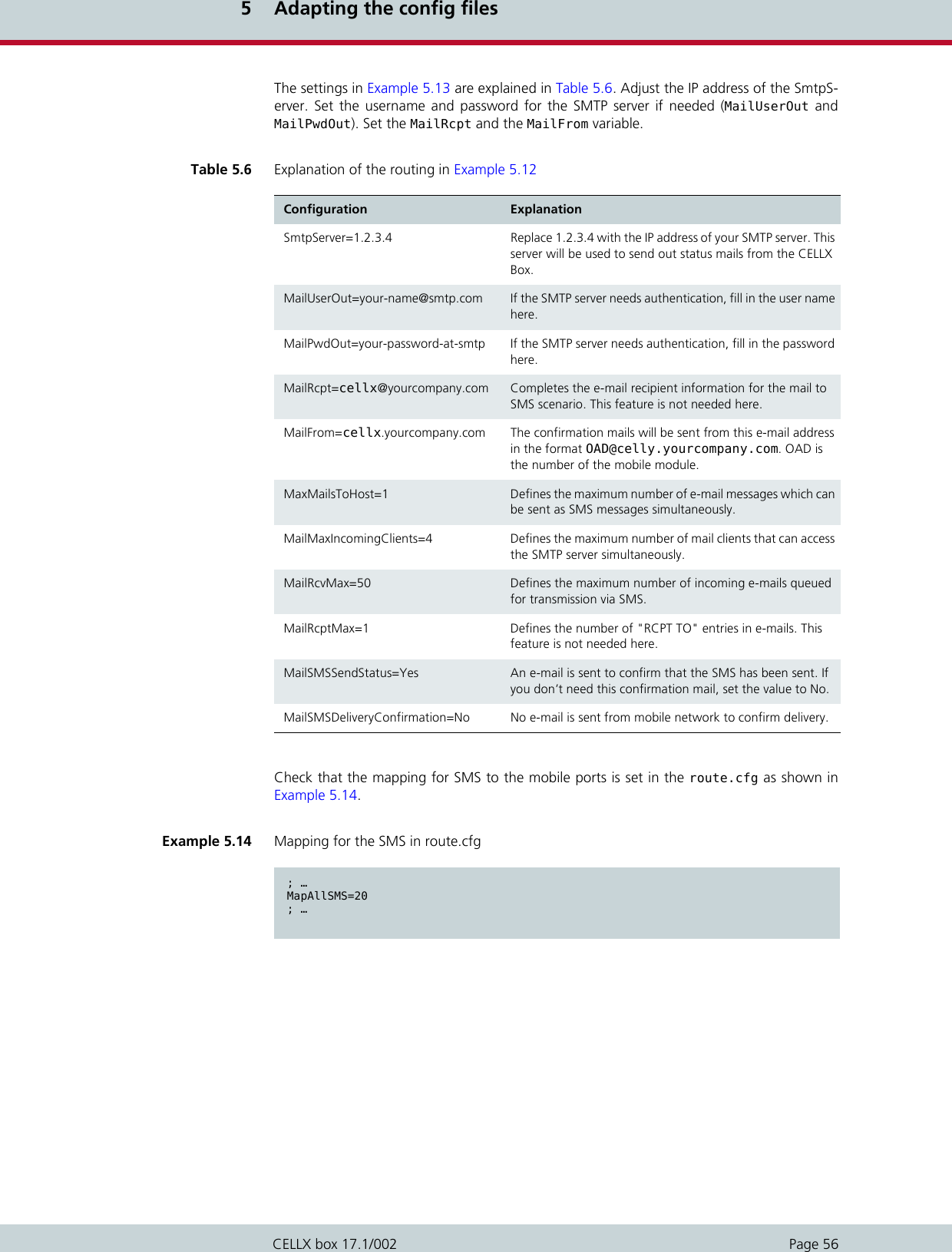
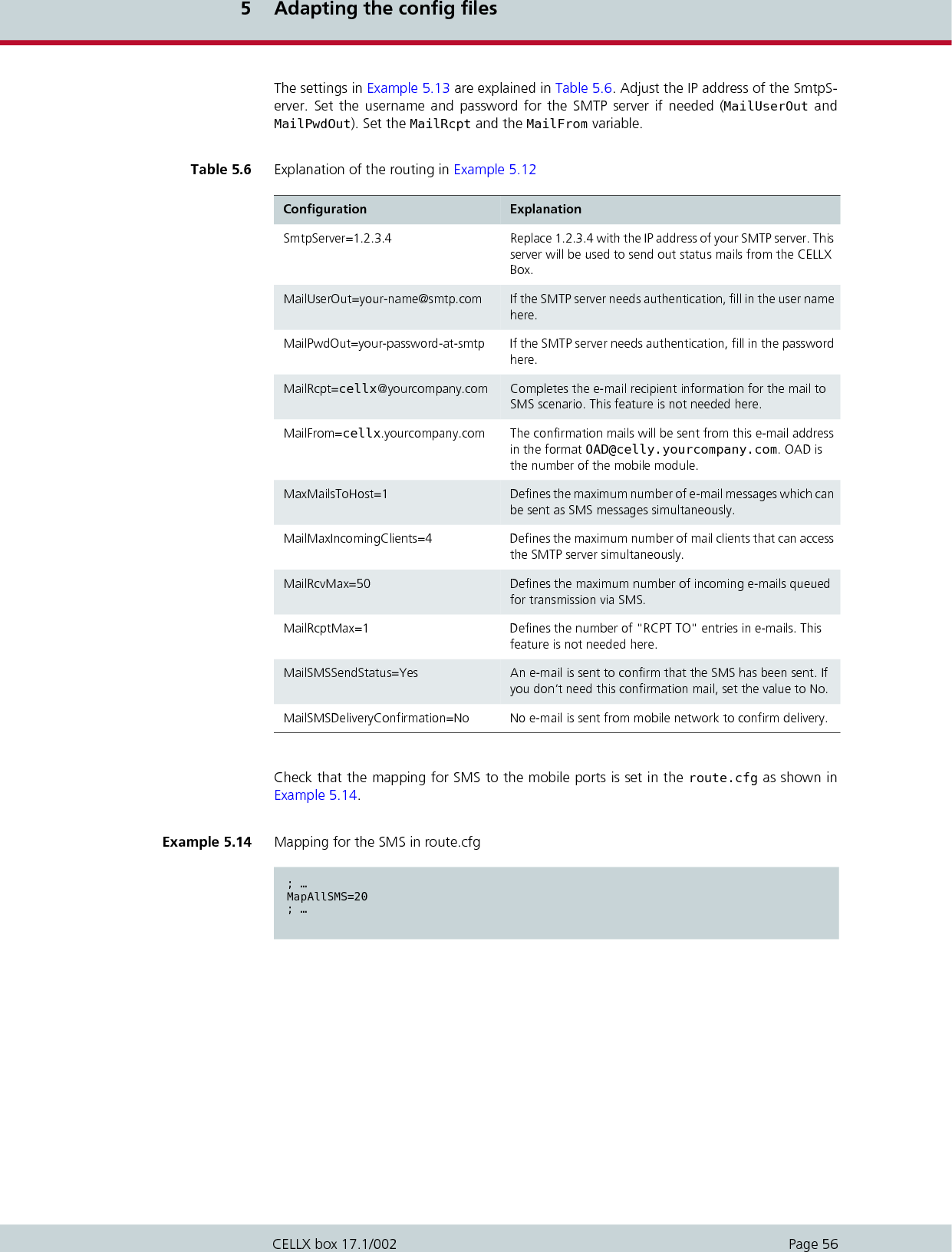
![5 Adapting the config filesPage 55CELLX box 17.1/002In the route.cfg set the entries shown in Example 5.12.The settings in Example 5.12 are explained in Table 5.5. If the internal numbering plan differsadjust the last mappings (MapAllplace*). 5.7 Mail to SMSThe CELLX Box converts e-mail messages to SMS messages. Send an e-mail to your CELLX Boxvia SMTP using any e-mail client. The CELLX Box converts the e-mail into an SMS messageand sends it to the mobile network. Configure the mail settings in the pabx.cfg as shown in Example 5.13. Example 5.12 Settings in the route.cfg for SMS callback ; …; send the incoming SMS to the msg.log fileRestrict20=@File 05; …; send SMS with CAL#number to intiate callback to sender and open a leg to numberMapAllCB=20MapAllDLA=$placeMapAllplace100=10MapAllplace101=11MapAllplace102=12MapAllplace103=13Table 5.5 Explanation of the routing in Example 5.12 Configuration ExplanationRestrict20=@File 05 This entry is already set in the route.cfg. It writes the incoming SMS to the file defined by MsgLog in the pabx.cfg.MapAllCB=20 The callback is done on CMDA port 20. MapAllDLA=$place A jump to the call routing is initialized. ’place’ is used as the flag for all callback routes. MapAllplace100=10 Sets the routing to the phone number 100 set in the SMS after CAL#. Example 5.12 defines only routes to the internal FXS ports – routes to mobile or VoIP are not defined (because of security/costs risks). Example 5.13 Mail server settings in the pabx.cfg [System]; …[Mail]SmtpServer=1.2.3.4MailUserOut=your-name@smtp.comMailPwdOut=your-password-at-smtp;MailRcpt=cellx@yourcompany.comMailFrom=cellx.yourcompany.comMaxMailsToHost=1MailMaxIncomingClients=4MailRcvMax=50MailRcptMax=1MailSMSSendStatus=YesMailSMSDeliveryConfirmation=No; …](https://usermanual.wiki/Teles-Informationstechnologien/GSM04VOIPUS/User-Guide-2293360-Page-55.png)
![6 MaintenancePage 58CELLX box 17.1/002This chapter describes the CDR and trace maintenance tasks.6.1 Call detail records (CDR)The CELLX Box writes call detail records of all connections to the system memory. The pathto the file (/boot/cdr.log) is set in the pabx.cfg (see Example 4.2 on page 31). All callswithout a connection will be written to the /boot/failed.log. New entries are always added to the end of the file. Example 6.1 shows a sample log file.Each line represents a call with the information listed in Table 6.1. Call Detail Records are intended for analysis of the CELLX Box’s activity only. They are not de- signed to be used for billing purposes, as the times they record may not be exact.iiExample 6.1 Sample cdr.log fileC1,25.11.09-10:16:20,25.11.09-10:16:27,9,111,,,,,0102,7,1f,0,,3663,10,,,C1,25.11.09-10:35:16,25.11.09-10:35:26,9,111,,,,,0102,10,1f,0,3,38922,14,,,C1,25.11.09-10:38:30,25.11.09-10:38:41,9,111,,,,,0102,11,90,0,3,38922,14,,,Table 6.1 Entries of the cdr.log file informations separated by commas Column Description0Version1Start time (format DD.MM.YY-hh.mm.ss)2 End time (format DD.MM.YY-hh.mm.ss)3Source. The following format applies: [node number:automatically set internal chan-nel number]4 Destination. The following format applies: [node number:automatically set internal channel number]5IMSI (optional)6 IP logging signaling: RTP (optional)7Audio codec used (optional)8 Frame size (optional)9Service indicator (see Table 6.2 on page 59)10 Call duration11 Cause values (see Table 6.3 on page 60)12 Charge from the public line (in units)13 Charge generated from the system (in units) (if configured)](https://usermanual.wiki/Teles-Informationstechnologien/GSM04VOIPUS/User-Guide-2293360-Page-58.png)
![6 MaintenancePage 60CELLX box 17.1/002The CDR entry in Example 6.2 includes IP addresses for signaling and voice data, audio codecand frame size.6.1.2 CDRs for callback and two stage callsIn the case of CDR entries for two-stage dialing/callback calls, the beginning and ending timesfor the first call leg is always used as the call time. The call time in seconds appears first forthe first leg, followed by a slash and the connection time for the second leg, as shown in Ex-ample 6.3.6.1.3 Specific cause valuesThe CELLX Box will generate cause values that represent an event, such as exceeding a de-fined limit. They are listed in Table 6.3. Example 6.2 Sample cdr.log file with VoIP information C1,24.11.09-16:52:20,24.11.09-16:52:22,401419,9777,,172.20.25.103:172.20.25.103,G711a,20,0101,2,10,0,,,11Example 6.3 Sample cdr.log file for callback and two-stage calls C1,24.11.09-17:15:29,24.11.09-17:15:57,[0002:01]CB,[0008:01]DLA,,172.20.25.103:172.20.25.103,G711a,20,0102,28/3,90,0,,,Table 6.3 Specific cause values Cause Value Description0a One of the following limits has been reached: Unit limit defined in the port’s subscriber lineUnit limit per SIM assignment via CELLX Box0b Maximum call duration assigned via CELLX Box has been reached0c Maximum call duration based on mapping entry settings has been reached0d Maximum number of minutes per SIM assignment via CELLX Box has been reached10, 1f Normal call termination (disconnected by calling party)](https://usermanual.wiki/Teles-Informationstechnologien/GSM04VOIPUS/User-Guide-2293360-Page-60.png)
![6 MaintenancePage 61CELLX box 17.1/0026.1.4 Missed calls listAll incoming calls that are not connected can be recorded in a list to facilitate return calls (/boot/failed.log). Each line represents an incoming call that was not accepted, with theinformation separated by commas, as listed in Table 6.4. Example 6.4 shows a sample failed.log file. The reason the connection could not be established is specified using DSS1 codes:91 – (user busy)ff – call not answered (disconnected by calling party)Table 6.4 Entries in the failed.log file separated by commas Column Description0Version1Start time (format DD.MM.YY-hh.mm.ss)2 Source. The following format applies: [node number:automatically set internal chan-nel number]3Destination. The following format applies: [node number:automatically set internal channel number]4IMSI5IP logging signaling: RTP6 Audio codec used7Frame size8 Service indicator9Cause values10 Call duration (if the call does not result in an Alerting, the entry will be -1)11 Number of call attempts12 Cell ID13 RSSIExample 6.4 Sample failed.log F1,24.11.09-16:13:08,[0006:01]IN,[0008:01]GSM,123456789123456,,,,0101,91,-1,1,34193,9F1,24.11.09-16:33:34,[0006:01]IN,[0008:01]GSM,123456789123456,,,,0101,91,-1,1,34193,12F1,24.11.09-16:35:19,[0006:01]IN,[0008:01]GSM,123456789123456,,,,0101,91,-1,1,34193,11F1,24.11.09-16:35:59,[0006:01]IN,[0008:01]GSM,123456789123456,,,,0101,91,-1,1,34193,11F1,24.11.09-16:37:29,[0006:01]IN,[0008:01]GSM,123456789123456,,,,0101,91,-1,1,34193,11F1,24.11.09-16:39:17,[0006:01]IN,[0008:01]GSM,123456789123456,,,,0101,ff,7,1,34193,11](https://usermanual.wiki/Teles-Informationstechnologien/GSM04VOIPUS/User-Guide-2293360-Page-61.png)
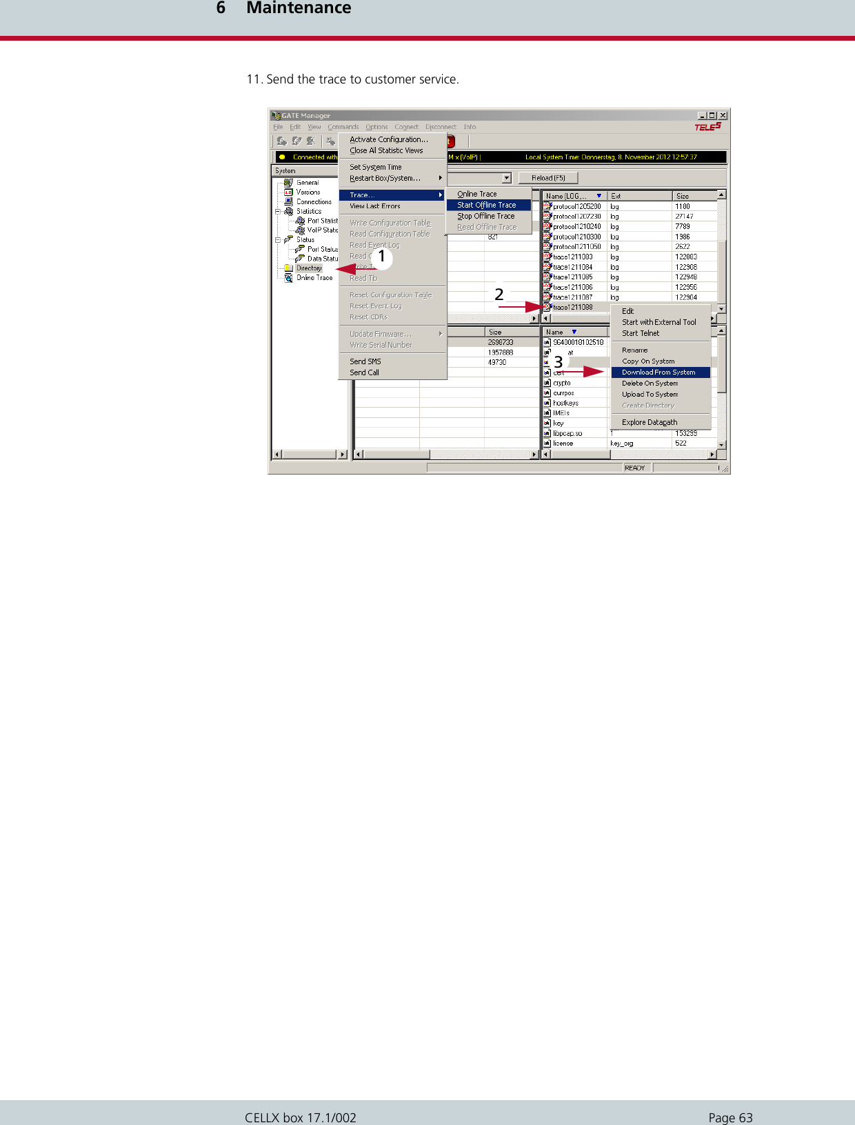
![6 MaintenancePage 62CELLX box 17.1/002The CDR contains the IP addresses for signaling and voice data. The first IP address is the sig-naling address and the second one is the RTP address.The IMSI is written after the IP addressesas shown in Example 6.5. In the case of missed-call entries for two stage dialing/callback calls, here is the connectiontime for the first leg: 6.2 TraceIf problems occur, do a trace with the GATE Manager and send it to customer service. Carryout the following steps: 1. Start the GATE Manager. 2. Select your CELLX Box and click the Connect button. 3. Enter the password (the default password is empty) and confirm with OK.4. Select Commands | Trace | Start Offline Trace. 5. The configuration dialog box for Online Trace opens. The default settings are cor-rect in many cases. 6. Confirm with OK – the trace starts. 7. Repeat the steps that led to these error.8. Stop the trace with Commands | Trace | Stop Offline Trace. 9. Select Directory in the menu. The trace files are listed in the rights pane. The filename is traceYYMMDD#.log. Where YY is the year, MM the month, DD the day and # anumber.10. Select the required file. Open the context menu with a right mouse click, selectDownload From System. Save the file to your PC, The default directory is %Pro-gramFiles%\teles\GATEManager\Data\<group>\<CELLX Box>. Example 6.5 Sample failed log with IP addresses F1,24.11.09-16:52:20,24.11.09-16:52:22,[0008:01]401419, [0006:01]IN777,262032441017556,172.20.25.103:172.20.25.103,G711a,20,0101,2,10,0,,34193,11Example 6.6 Sample failed.log for a two-stage dialing call F1,25.11.09-14:11:10,[0002:01]CB,DLA,,,,,0102,11,14,1,,](https://usermanual.wiki/Teles-Informationstechnologien/GSM04VOIPUS/User-Guide-2293360-Page-62.png)