Teles Informationstechnologien GSM04VOIPUS Mobile Gateway User Manual CELLX Box
Teles AG Informationstechnologien Mobile Gateway CELLX Box
Users manual

CELLX Box
Systems Manual
Software version 17.1

© Copyright 2014 TELES AG Informationstechnologien. All rights reserved.
CELLX®, TELES®, IntraSTAR®, Intra*®, iGATE®, and iSWITCH® are registered trademarks of TELES AG
Informationstechnologien. All other trademarks used are the property of their respective owners.
The supplied hardware/software systems are protected by copyright and can be used solely by their lawful owners.
All text and figures in this publication have been compiled with great attention to detail. Nonetheless, inaccuracies and
typographical errors cannot be entirely avoided. TELES AG Informationstechnologien provides this document 'as is' without
warranty of any kind, expressed or implied. TELES AG Informationstechnologien reserves the right to make changes in
product design or specifications without notice.
Systems Manual
CELLX Box
CELLX Box 17.1
TELES COMMUNICATIONS CORP.
2400 Skyfarm Drive,
Hillsborough, CA 94010
United States
Phone: +1 646-225 65 98
E-Mail: cellx@teles.com
Internet: http://www.teles.com/cellx/index.html
Revised: 20 March 2014 002Software version: 17.1

Table of Contents
Page 3
CELLX box 17.1/002
Preface. . . . . . . . . . . . . . . . . . . . . . . . . . . . . . . . . . . . . . . . . . . . . 5
1 Overview. . . . . . . . . . . . . . . . . . . . . . . . . . . . . . . . . . . . . . . . . . . 7
1.1 Features . . . . . . . . . . . . . . . . . . . . . . . . . . . . . . . . . . . . . . . . . . . . . . . . . . . . . . . . . . . . . .8
1.2 Implementation scenarios . . . . . . . . . . . . . . . . . . . . . . . . . . . . . . . . . . . . . . . . . . . . . . .9
1.2.1 CELLX Box last mile . . . . . . . . . . . . . . . . . . . . . . . . . . . . . . . . . . . . . . . . . . . . . . . . . . . .10
1.2.2 CELLX Box failover. . . . . . . . . . . . . . . . . . . . . . . . . . . . . . . . . . . . . . . . . . . . . . . . . . . . .10
1.2.3 CELLX Box cost saving model . . . . . . . . . . . . . . . . . . . . . . . . . . . . . . . . . . . . . . . . . . . .11
2 System security and hardware overview . . . . . . . . . . . . . . . . 12
2.1 Safety and security precautions. . . . . . . . . . . . . . . . . . . . . . . . . . . . . . . . . . . . . . . . . .13
2.2 System security . . . . . . . . . . . . . . . . . . . . . . . . . . . . . . . . . . . . . . . . . . . . . . . . . . . . . . .13
2.2.1 Transport . . . . . . . . . . . . . . . . . . . . . . . . . . . . . . . . . . . . . . . . . . . . . . . . . . . . . . . . . . . .13
2.2.2 Operating conditions . . . . . . . . . . . . . . . . . . . . . . . . . . . . . . . . . . . . . . . . . . . . . . . . . .13
2.2.3 Connecting Cables . . . . . . . . . . . . . . . . . . . . . . . . . . . . . . . . . . . . . . . . . . . . . . . . . . . . .14
2.2.4 Antenna Input . . . . . . . . . . . . . . . . . . . . . . . . . . . . . . . . . . . . . . . . . . . . . . . . . . . . . . . .14
2.2.5 Damage . . . . . . . . . . . . . . . . . . . . . . . . . . . . . . . . . . . . . . . . . . . . . . . . . . . . . . . . . . . . .14
2.2.6 Repairs . . . . . . . . . . . . . . . . . . . . . . . . . . . . . . . . . . . . . . . . . . . . . . . . . . . . . . . . . . . . . .14
2.2.7 Upgrades . . . . . . . . . . . . . . . . . . . . . . . . . . . . . . . . . . . . . . . . . . . . . . . . . . . . . . . . . . . .15
2.2.8 Cleaning . . . . . . . . . . . . . . . . . . . . . . . . . . . . . . . . . . . . . . . . . . . . . . . . . . . . . . . . . . . . .15
2.2.9 Potentially explosive atmospheres . . . . . . . . . . . . . . . . . . . . . . . . . . . . . . . . . . . . . . . .15
2.2.10 Radio wave exposure information . . . . . . . . . . . . . . . . . . . . . . . . . . . . . . . . . . . . . . . .15
2.2.11 Personal medical devices. . . . . . . . . . . . . . . . . . . . . . . . . . . . . . . . . . . . . . . . . . . . . . . .15
2.2.12 Environmental considerations . . . . . . . . . . . . . . . . . . . . . . . . . . . . . . . . . . . . . . . . . . .15
2.2.13 Protecting the operating system . . . . . . . . . . . . . . . . . . . . . . . . . . . . . . . . . . . . . . . . .15
2.2.14 CDR files . . . . . . . . . . . . . . . . . . . . . . . . . . . . . . . . . . . . . . . . . . . . . . . . . . . . . . . . . . . . .16
2.2.15 Network security . . . . . . . . . . . . . . . . . . . . . . . . . . . . . . . . . . . . . . . . . . . . . . . . . . . . . .16
2.3 Physical description of the CELLX Box . . . . . . . . . . . . . . . . . . . . . . . . . . . . . . . . . . . . .17
3 CELLX Box installation . . . . . . . . . . . . . . . . . . . . . . . . . . . . . . . 19
3.1 Checklist. . . . . . . . . . . . . . . . . . . . . . . . . . . . . . . . . . . . . . . . . . . . . . . . . . . . . . . . . . . . .20
3.2 Unpacking the shipment. . . . . . . . . . . . . . . . . . . . . . . . . . . . . . . . . . . . . . . . . . . . . . . .20
3.3 Cabling . . . . . . . . . . . . . . . . . . . . . . . . . . . . . . . . . . . . . . . . . . . . . . . . . . . . . . . . . . . . . .21
3.3.1 Analog wiring (optional for FXS) . . . . . . . . . . . . . . . . . . . . . . . . . . . . . . . . . . . . . . . . .21
3.3.2 Ethernet wiring . . . . . . . . . . . . . . . . . . . . . . . . . . . . . . . . . . . . . . . . . . . . . . . . . . . . . . .21
3.3.3 Antenna cabling . . . . . . . . . . . . . . . . . . . . . . . . . . . . . . . . . . . . . . . . . . . . . . . . . . . . . .21
3.3.4 Power cabling . . . . . . . . . . . . . . . . . . . . . . . . . . . . . . . . . . . . . . . . . . . . . . . . . . . . . . . .22
3.4 LED functionality. . . . . . . . . . . . . . . . . . . . . . . . . . . . . . . . . . . . . . . . . . . . . . . . . . . . . .22
4 Configuration . . . . . . . . . . . . . . . . . . . . . . . . . . . . . . . . . . . . . . 23
4.1 Configuration tools . . . . . . . . . . . . . . . . . . . . . . . . . . . . . . . . . . . . . . . . . . . . . . . . . . . .24
4.2 Skills needed for a configuration setup . . . . . . . . . . . . . . . . . . . . . . . . . . . . . . . . . . .24
4.3 Assigning an IP address to the CELLX Box . . . . . . . . . . . . . . . . . . . . . . . . . . . . . . . . .24
4.4 Connecting to the CELLX Box with GATE Manager . . . . . . . . . . . . . . . . . . . . . . . . . .26
4.5 Required information for further scenarios . . . . . . . . . . . . . . . . . . . . . . . . . . . . . . . .27
4.6 The CELLX Box config files . . . . . . . . . . . . . . . . . . . . . . . . . . . . . . . . . . . . . . . . . . . . . .29
4.6.1 The pabx.cfg config file . . . . . . . . . . . . . . . . . . . . . . . . . . . . . . . . . . . . . . . . . . . . . . . .30
4.6.2 The ip.cfg config file . . . . . . . . . . . . . . . . . . . . . . . . . . . . . . . . . . . . . . . . . . . . . . . . . . .32
Table of Contents

Table of Contents
Page 4
CELLX box 17.1/002
4.6.3 The route.cfg config file . . . . . . . . . . . . . . . . . . . . . . . . . . . . . . . . . . . . . . . . . . . . . . . .33
4.6.3.1 The Restrict variable used in the route.cfg . . . . . . . . . . . . . . . . . . . . . . . . . . . . . . . . .34
4.6.3.2 The MapAll variable used in the route.cfg . . . . . . . . . . . . . . . . . . . . . . . . . . . . . . . . .35
4.6.3.3 The Redirect variable used in the route.cfg. . . . . . . . . . . . . . . . . . . . . . . . . . . . . . . . .36
4.6.4 The route.cfg for the last mile scenario. . . . . . . . . . . . . . . . . . . . . . . . . . . . . . . . . . . .37
4.6.5 Configuration files for VoIP scenarios . . . . . . . . . . . . . . . . . . . . . . . . . . . . . . . . . . . . .39
5 Adapting the config files . . . . . . . . . . . . . . . . . . . . . . . . . . . . . 43
5.1 Editing the config files . . . . . . . . . . . . . . . . . . . . . . . . . . . . . . . . . . . . . . . . . . . . . . . . .44
5.2 Securing the CELLX Box . . . . . . . . . . . . . . . . . . . . . . . . . . . . . . . . . . . . . . . . . . . . . . . .44
5.2.1 Setting the password for the GATE Manager . . . . . . . . . . . . . . . . . . . . . . . . . . . . . . .45
5.2.2 Adjusting the firewall setting. . . . . . . . . . . . . . . . . . . . . . . . . . . . . . . . . . . . . . . . . . . .45
5.3 VoIP configuration . . . . . . . . . . . . . . . . . . . . . . . . . . . . . . . . . . . . . . . . . . . . . . . . . . . .46
5.3.1 VoIP settings for a public VoIP provider . . . . . . . . . . . . . . . . . . . . . . . . . . . . . . . . . . .47
5.3.1.1 VoIP profile for the provider . . . . . . . . . . . . . . . . . . . . . . . . . . . . . . . . . . . . . . . . . . . .47
5.3.1.2 Registrar profile defined for the provider. . . . . . . . . . . . . . . . . . . . . . . . . . . . . . . . . .49
5.3.1.3 Call routing for outgoing calls to the provider . . . . . . . . . . . . . . . . . . . . . . . . . . . . . .50
5.3.2 VoIP settings for local SIP UA . . . . . . . . . . . . . . . . . . . . . . . . . . . . . . . . . . . . . . . . . . . .51
5.3.2.1 VoIP profile for the local SIP UAs . . . . . . . . . . . . . . . . . . . . . . . . . . . . . . . . . . . . . . . . .51
5.3.2.2 Call routing for calls to and from the local SIP device . . . . . . . . . . . . . . . . . . . . . . . .52
5.4 Rerouting or failover. . . . . . . . . . . . . . . . . . . . . . . . . . . . . . . . . . . . . . . . . . . . . . . . . . .52
5.5 Cost saving routing . . . . . . . . . . . . . . . . . . . . . . . . . . . . . . . . . . . . . . . . . . . . . . . . . . . .53
5.6 Callback initiated by SMS . . . . . . . . . . . . . . . . . . . . . . . . . . . . . . . . . . . . . . . . . . . . . . .54
5.7 Mail to SMS . . . . . . . . . . . . . . . . . . . . . . . . . . . . . . . . . . . . . . . . . . . . . . . . . . . . . . . . . .55
6 Maintenance . . . . . . . . . . . . . . . . . . . . . . . . . . . . . . . . . . . . . . . 57
6.1 Call detail records (CDR) . . . . . . . . . . . . . . . . . . . . . . . . . . . . . . . . . . . . . . . . . . . . . . . .58
6.1.1 Activating peer data for VoIP calls. . . . . . . . . . . . . . . . . . . . . . . . . . . . . . . . . . . . . . . .59
6.1.2 CDRs for callback and two stage calls . . . . . . . . . . . . . . . . . . . . . . . . . . . . . . . . . . . . .60
6.1.3 Specific cause values . . . . . . . . . . . . . . . . . . . . . . . . . . . . . . . . . . . . . . . . . . . . . . . . . . .60
6.1.4 Missed calls list. . . . . . . . . . . . . . . . . . . . . . . . . . . . . . . . . . . . . . . . . . . . . . . . . . . . . . . .61
6.2 Trace. . . . . . . . . . . . . . . . . . . . . . . . . . . . . . . . . . . . . . . . . . . . . . . . . . . . . . . . . . . . . . . .62
Preface
Page 5
CELLX box 17.1/002
In this manual
This manual is set up to guide you through the installation of your CELLX Box. It is written for
network administrators who use and maintain the gateway. To use this manual you should
have some experience working with networking devices and be familiar with the concepts
and terminology of telecommunication technology. Make sure you familiarize yourself thor-
oughly with the safety and security precautions detailed in Chapter 2 System security and
hardware overview on page 12 before you begin to install your CELLX Box. TELES is not liable
for any damage or injury resulting from a failure to follow these safety and security instruc-
tions!
In addition to this manual there is a parameter manual summarizing the configuration param-
eters used in the config files.
Conventions
This document uses the following typographic conventions:
Bold – important information, and items from the GUI and the menu.
Code – file names, variables, and constants in config files or commands in body text.
"Conventions" on page 5 – cross-references can be accessed in the PDF by a single
mouse click.
Safety Symbols
The following symbols are used to indicate important information and to describe levels of
possible danger.
Configuration data or extracts are written in single-column tables with a gray
background.
Note
Useful information with no safety implications.
Attention
Information that must be adhered to as it is necessary to ensure that the sys-
tem functions correctly and to avoid material damage.
Warning
Danger. Could cause personal injury or damage to the system.
Dangerous voltage
Could cause injury by high voltage and/or damage the system.
Electrostatic discharge
Components at risk of discharge must be grounded before being touched.
Explosion hazard
Injury hazard due to explosions endangering the person or the system.
i
i
!
!
!
!
Preface

Organization
Page 6
CELLX box 17.1/002
This guide is organized into the following chapters.
Chapter 1 “Overview”: describes the general features of the CELLX Box and the
main features for VoIP, telephony, and mobile.
Chapter 2 “System security and hardware overview”: starts with the safety and
security precautions. Make sure that everyone who works with the
CELLX Box is aware of these precautions. The CELLX Box described at
the end of this chapter.
Chapter 3 “CELLX Box installation”: contains information on hardware installa-
tion of your CELLX Box. Follow the easy instructions to set up your
CELLX Box in a matter of minutes.
Chapter 4 “Configuration”: describes how to connect the CELLX Box to the GATE
Manager and provides an introduction to the configuration. Before
you begin you must be familiar with the hardware, and the CELLX Box
must be installed at the location and connected as described in
Chapter 3 "CELLX Box installation" on page 19. After installation, the
CELLX Box is ready to carry out maintenance tasks using the GATE
Manager, and to configure implementation scenarios using VoIP.
Chapter 5 “Adapting the config files”: describes some frequent configuration
scenarios.
Chapter 6 “Maintenance”: describes the CDR and trace maintenance tasks.
Organization

1 Overview

1Overview
Page 8
CELLX box 17.1/002
This chapter describes the general features of the CELLX Box and the main features
for VoIP, telephony, and mobile.
The CELLX Box is a media converter that facilitates the connection of voice over IP (VoIP) with
mobile networks. The connection to telephone equipment using FXS is optional. It converts
line-based transmission on mobile side to packet-based transmission in the IP network and
vice versa. Incoming traffic arrives at one CELLX Box, which routes the calls according to their
destination and attributes. Table 1.1 list the main variants of the CELLX Box.
The CELLX Box contains two Gigabyte Ethernet interfaces to the IP network.
1.1 Features
Mobile
4 GSM or 3G (UMTS) channels
Built-in SIM-card server support for unlimited SIMs per channel with vGATE SIM Unit.
Individual timers for each SIM /call
Possible to configure individual mobile bands
Radius accounting request contains SIM’s IMSI to enable SIM-specific billing
Support for vGATE sub-limits
Number portability
Mobile-specific configuration parameters now definable per mobile network (LAIN)
vGATE RoutingManager support
E-mails to SMS: support for SMS delivery report
Table 1.1 Possible product variants of the CELLX Box
Product name Description
CELLX 3G–4 CELLX Box with four 3G mobile interfaces.
CELLX GSM–4 CELLX Box with four GSM mobile interfaces.
CELLX 3G–4 FXS CELLX Box with four 3G mobile and four FXS interfaces.
CELLX GSM–4 FXS CELLX Box with four GSM mobile and four FXS interfaces.
CELLX 3G–4 BRI-2 CELLX Box with four 3G mobile, two BRI interfaces.
CELLX GSM–4 BRI-2 CELLX Box with four GSM mobile, two BRI interfaces.

1Overview
Page 9
CELLX box 17.1/002
VoIP
8 media channels
H.323 v.4 / SIP v.2 signaling (RFC 3261), operating in parallel
Various audio codecs: G.711, G.723.1, G.726, G.728, G.729, GSM, iLBC
Fax: T.38
Data: clear channel
RTP multiplexing (reduces bandwidth required for RTP data by up to 60%)
ENUM client
Echo cancellation G.168–2000
Silence suppression, comfort noise generation, voice activity detection
Support for multiple gatekeepers and multiple registrars
STUN client
Traffic shaping
Adjustable time interval for echo detection in VoIP
FXS (optional)
4 analog lines (FXS)
Fax/modem detection (UDT)
Charging impulse (12/16kHz)
Integrated line echo cancellation
Power feeding for FXO devices
Dial-tone and ring-tone generation
Calling Line Identification (CLIR) on FXS ports
LCR engine
Multiple VoIP-provider logins
Multiple PSTN routing methods
Multilevel alternative routing
Dynamic failover to mobile network
Dynamic failover to VoIP
General
Ringtone generation
Configurable ToS/DivServ
AOC generation
2nd separate Gigabit Ethernet interface
Status indication via LEDs
Integrated mail client capable of SMTP authentication
E-mail messages can trigger calls and play attached announcements
Automatic test call
Redial function
Autodial function
1.2 Implementation scenarios
The CELLX Box supports the following implementation scenarios:
CELLX Box last mile (see Chapter 1.2.1 on page 10),
CELLX Box failover (see Chapter 1.2.2 on page 10), and
CELLX Box for cost savings (see Chapter 1.2.3 on page 11)
1Overview
Page 10
CELLX box 17.1/002
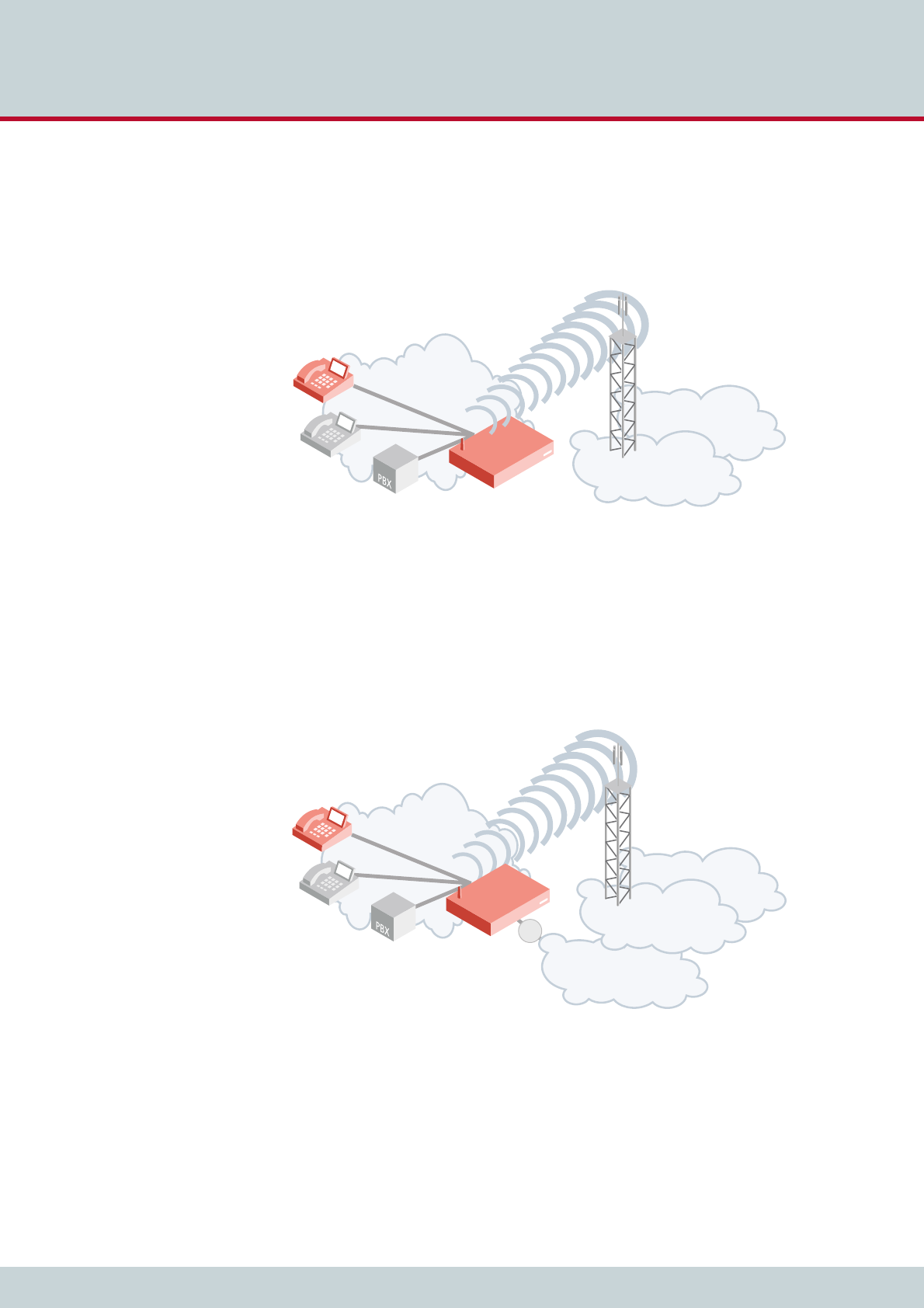
1.2.1 CELLX Box last mile
The CELLX Box provides voice via the mobile network, which offers a reliable alternative to
traditional landline connections for voice connections. In rural areas with no landline avail-
able, all you need for immediate communication is an CELLX Box and mobile network cover-
age. The CELLX Box works as a gateway to the mobile interface for voice.
Figure 1.1 The CELLX Box in a last mile scenario
1.2.2 CELLX Box failover
The CELLX Box is used if the primary VoIP connection fails, in which case it routes outgoing
calls automatically via mobile networks. In this case the CELLX Box works as an mobile gate-
way that can augment landline connectivity with wireless connectivity to the mobile network.
In case of landline connectivity failure, the CELLX Box provides a backup solution to maintain
voice communications. The CELLX Box will route all outbound calls to the mobile network.
Inbound calls from the mobile network will be routed to the connected telephone equipment.
Figure 1.2 The CELLX Box in a failover scenario
PSTN
local network
mobile
network
CELLX
PSTN
local network
mobile
network
CELLX
VoIP
x
1Overview
Page 11
CELLX box 17.1/002
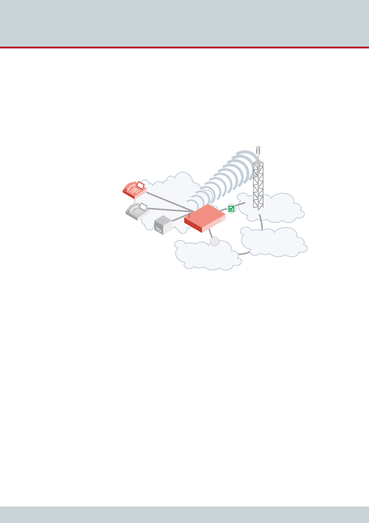
1.2.3 CELLX Box cost saving model
The CELLX Box also has an effective call routing engine. It turns expensive fixed–to–cellular
calls into cheaper cellular–to–cellular calls. Calls from the office to staff cellular phones may
even be free of charge.
Cellular calls outside the home network are usually subject to high outgoing roaming fees. A
CELLX Box callback solution may help to replace those fees with lower incoming roaming
fees.
This will help to reduce your calling costs significantly.
Figure 1.3 The CELLX Box in a cost saving scenario
local network
mobile
network
PSTN
VoIP
x
CELLX

2 System security and hardware overview
2 System security and hardware overview
Page 13
CELLX box 17.1/002
This chapter starts with the safety and security precautions. Make sure that every-
one who works with the CELLX Box is aware of these precautions. The CELLX Box
described at the end of this chapter.
2.1 Safety and security precautions
Please be sure and take time to read this section to ensure your personal safety and proper
operation of your CELLX Box. To avoid personal injury or damage to the CELLX Box, please
follow all safety instructions before you begin working on your CELLX Box. CELLX Boxes are
CE certified and fulfill the legally specified safety regulations, including EMC (electromagnetic
compatibility) and LVD (low voltage directive) requirements. The manufacturer assumes no li-
ability for consequential damages or for damages resulting from unauthorized changes.
The symbols described on Chapter "Safety Symbols" on page 5 are used to indicate impor-
tant information and to describe levels of possible danger.
Before you begin to setup the CELLX Box, please take note of the following advice.
2.2 System security
This section describes all points crucial to the CELLX Box’s system security.
2.2.1 Transport
Disconnect all cables before moving the CELLX Box. As a protection against jolts and impact,
this device should be transported in its original packaging only.
Condensation can occur if the device is brought from a cold environment into the room
where it is to be operated. The device must be absolutely dry prior to being operated. Accord-
ingly, an acclimatization period of at least two hours is required.
2.2.2 Operating conditions
The CELLX Box’s location must support normal operation in accordance with EN ETS 300 386.
Make sure you install the system in a clean, dry, dust-free location. If possible, use an air-con-
ditioned site.
Do not subject the device to direct sunlight.
Danger of electric shock - do only use the power supply included in delivery. Do not use a bro-
ken power supply. The power supply run on 110 V.
Bear in mind that telephone and WAN lines are also energized and can cause electric shocks.
Wire your system using only the cables included in the package contents. Use only proper Eth-
ernet cables.
Do not insert foreign objects into openings in the device. Conductible objects can cause short-
circuiting that results in fire, electric shock, or damage to the device.
Never work on the CELLX Box or connect or disconnect cables during a thunderstorm.
Do not open the CELLX Box or its power supply. Changes in the device are not permitted.
Be sure to respect country-specific regulations, standards or guidelines for accident preven-
tion.
Tips for EMC Protection: Use shielded cables. Do not remove any housing components. They
provide EMC protection.
i
i
2 System security and hardware overview
Page 14
CELLX box 17.1/002
The site must be free of strong electrical or magnetic fields, which cause disrupted signals
and, in extreme cases, system failure.
The site must maintain a temperature between 32°F and 90°F. Be sure to guard against tem-
perature fluctuations. Resulting condensation can cause a short circuit. The humidity level
may not exceed 80%.
To avoid overheating the system, make sure the site provides adequate ventilation.
Regular servicing ensures that your CELLX Box runs trouble-free. Servicing also includes look-
ing after the room in which the CELLX Box is set up. Ensure that the air-conditioning and its
filter system are regularly checked and that the premises are cleaned on a regular basis.
Electrical devices may not be used by individuals who are not aware of the dangers of elec-
tricity and/or incorrect use thereof.
2.2.3 Connecting Cables
Lay all cables in a manner that is not hazardous to pedestrian traffic. The power cord must be
unplugged from the AC line socket in order to completely disconnect the equipment (e.g. in
emergencies).
Cables should not be connected or disconnected during thunderstorms!
2.2.4 Antenna Input
The antenna must be protected against destruction due to lightning. The base of the antenna
must be grounded.
2.2.5 Damage
For safety reasons, if the CELLX Box exhibits visible damage or has been exposed to moisture,
then further operation should be discontinued! In this case, please ensure that the CELLX Box
is disabled so it cannot be used by anyone else.
2.2.6 Repairs
Repairs must be performed only by qualified personnel. Only use replacement parts that com-
ply with device safety standards.
Always unplug the AC line connector before opening the device!
Power: The electrical facilities must comply with applicable regulations.
The operating voltage and frequency may not exceed or fall below what is stated on the label
of the power supply.
Antenna: TELES contains no provision or protective device against power surges or lightning
strikes.
The installation of the antenna must fulfill all necessary safety requirements. Employ the ser-
vices of a professional antenna installer.
Use shielded cables for EMC protection.
Do not remove any housing components. They provide EMC protection.

2 System security and hardware overview
Page 15
CELLX box 17.1/002
2.2.7 Upgrades
Only install system upgrades that are specifically intended for this device. Installing other up-
grades can damage the system or violate safety standards and radio interference regulations.
2.2.8 Cleaning
Before cleaning, unplug the AC line connector. Do not use scouring powder or solvents harm-
ful to plastics.
Do not allow liquids to penetrate into the interior of the CELLX Box. A dry cloth suffices for
cleaning the housing surface. A cloth dipped in water containing a mild detergent and then
wrung out well can be used for heavier stains.
2.2.9 Potentially explosive atmospheres
Do not use this product in an area where a potentially explosive atmosphere exists.
2.2.10 Radio wave exposure information
This product is a low-power radio transmitter and receiver. During operation, it emits low lev-
els of radio frequency energy.
Several organizations, e.g. ICNIRP (International Commission on Non-Ionizing Radiation Pro-
tection) and IEEE (The Institute of Electrical and Electronics Engineers Inc.) developed safety
guidelines about permitted levels of radio wave exposure for the general population, based
on thorough scientific studies.
To meet the maximum permissible value for radio wave exposure, a distance of 20 centime-
ters must be kept if running one mobile channel, and an additional 20 centimeters for every
further mobile channel.
2.2.11 Personal medical devices
Radio waves may affect the operation of cardiac pacemakers and other implanted equip-
ment. To limit the risk, a distance of 20 centimeters must be kept if running one mobile chan-
nel, and an additional 20 centimeters for every further mobile channel. If you suspect that
interference is taking place, immediately move away from the device.
2.2.12 Environmental considerations
Take care to ensure proper disposal of the CELLX Box when it is no longer to be used.
2.2.13 Protecting the operating system
Changing configuration data may lead to malfunctions and/or misrouting, as well as possible
consequential damage. Make changes at your own risk. TELES is not liable for any damage
resulting from, or in relation to, such changes. Please thoroughly check any changes you or
a third party have made to your configuration!
Make sure the flash disk contains enough storage space. Download log files and delete them
from the CELLX Box on a regular basis to ensure your CELLX Box’s reliability.
All files with the extension *.log can be deleted.

2 System security and hardware overview
Page 16
CELLX box 17.1/002
2.2.14 CDR files
Call Detail Records are intended for analysis of the CELLX Box’s activity only. They are not de-
signed to be used for billing purposes, as the times they record are not always exact.
2.2.15 Network security
Every day hackers develop new ways to break into systems through the Internet. While we
takes great care to ensure the security of its systems, any system with access through the In-
ternet is only as secure as its user makes it. Therefore, to avoid unwanted security breaches
and resulting system malfunctions, you must take the following steps to secure your CELLX
Box if you connect it to the Internet:
Use an application gateway or a packet firewall.
To limit access to the CELLX Box to secure remote devices, delete the default route and
add individual secure network segments.
Access to the CELLX Box via Telnet, FTP or GATE Manager must be password protected.
Do not use obvious passwords (anything from sesame to your mother-in-laws maiden
name). Bear in mind: the password that is easiest to remember is also likely to be easiest
to crack.
The firewall must support the following features:
Protection against IP spoofing
Logging of all attempts to access the CELLX Box
The firewall must be able to check the following information and only allow trusted users to
access the CELLX Box:
IP source address
IP destination address
Protocol (whether the packet is TCP, UDP, or ICMP)
TCP or UDP source port
TCP or UDP destination port
ICMP message type
For operation and remote administration of your CELLX Box, open the following ports only
when the indicated services are used:
Inaccuracies in the generation of CDRs may occur for active connections if traffic is flowing on
the system while modifications in configuration or routing files are activated.
i
i
Table 2.1 Default ports used for specific services
Service Protocol Port
FTP TCP 21 (default, can be set)
Telnet (for debug access only) TCP 23 (default, can be set)
SMTP TCP 25
DNS forward UDP 53
HTTP TCP 80 (default, can be set)
NTP UDP 123
2 System security and hardware overview
Page 17
CELLX box 17.1/002
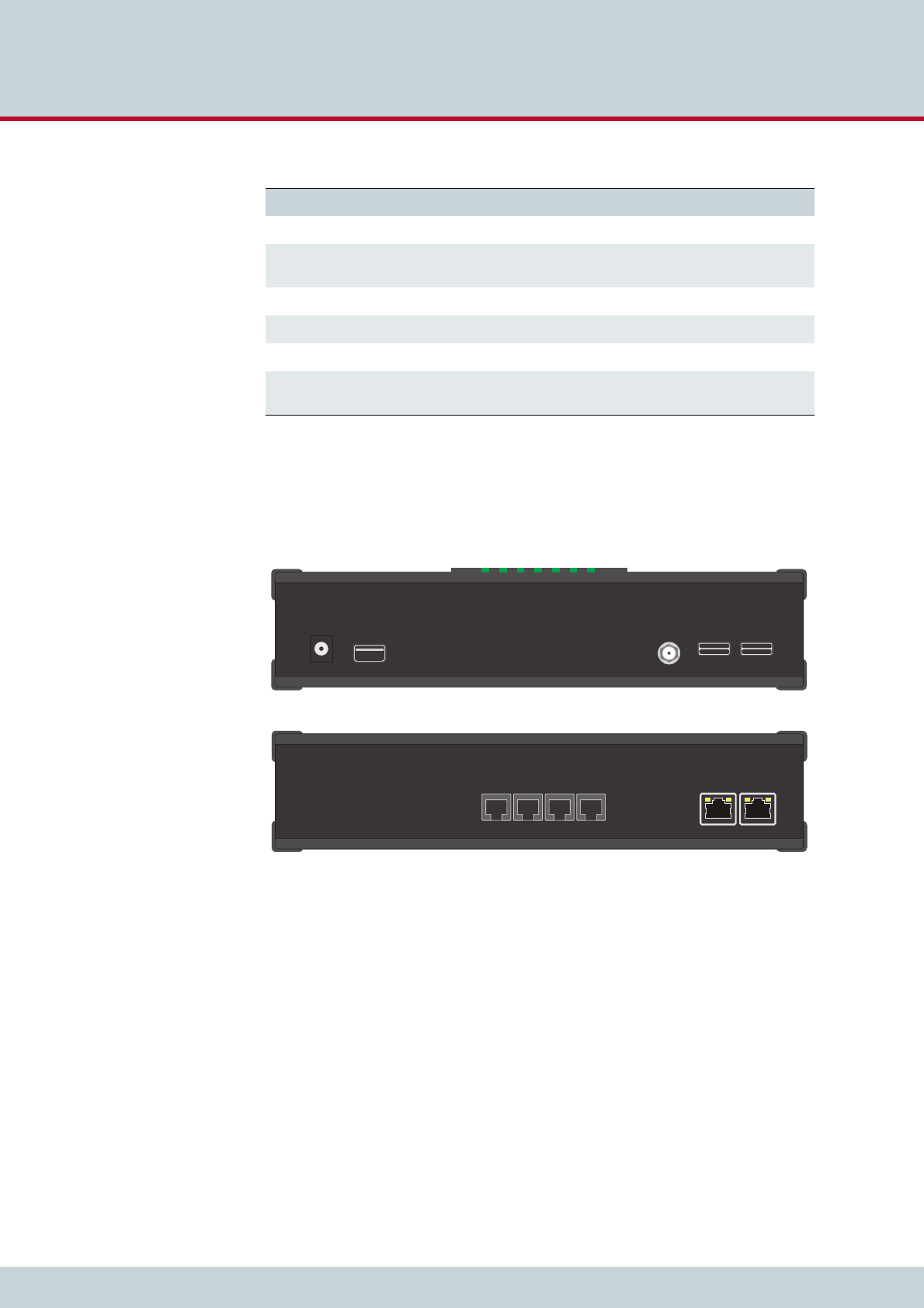
2.3 Physical description of the CELLX Box
Figure 2.1 shows front and rear views of the CELLX Box.
Figure 2.1 Front and rear views of the CELLX Box
SNMP UDP 161 (default, can be set)
H.225 registration, admission,
status
UDP 1719 (default, can be set)
H.225 signaling TCP 1720 (default, can be set)
GATE Manager TCP 4445 (default, can be set)
SIP signaling UDP / TCP 5060 (default, can be set)
RTP UDP 29000-29120 (default, can be
set)
Table 2.1 Default ports used for specific services (continued)
Service Protocol Port
ETH1ETH2
FXS1 FXS2 FXS3 FXS4
Antenna
USB
12V=
CX
ELL
SIM 1
SIM 2
SIM 3
SIM 4
Front view of the CELLX Box
Rear view of the CELLX Box
LED 1234567

2 System security and hardware overview
Page 18
CELLX box 17.1/002
Table 2.2 summarizes the technical data of the CELLX Box.
Table 2.2 Technical data of the CELLX Box
Feature Description
Dimensions and weight Height: 56 mm (2.20 in.)
Width: 243 mm (9.57 in.)
Depth: 166 mm (6.54 in.)
Weight: 0.7 kg (1.54 lbs.)
Interfaces 2 Gigabit Ethernet: on rear panel
optional 4 FXS or 2 BRI: on rear panel
1 mobile antenna connector: SMA (on front panel)
1 USB – not active / usable (on front panel)
1 power 12 V (on front panel)
Jacks The jacks on the CELLX Box have fulfilled the requirements of the follow-
ing safety standards.
ETH jacks: SELV
FXS jacks: TNV3
ISDN jacks: SELV
LED Please see Table 3.1 on page 22
Power supply Type: DSA-42D-12 1 120350
Input voltage: 100–240 V AC; 50 / 60 Hz; 1,2 A maximum
Output voltage: 12V; 3.5 A; 42 W
Dimensions: 118 (L) x 48.5 (W) x 35 (H) mm
Weight: 230g
Jack plug: 5.5 x2.1x12mm
Tested and certified as TÜV-GS (EN60950-1), UL/CUL (UL60950-1),
T-LICENSE (BS EN60950-1), SAA (AS/NZ60950), CCC (GB4943)
EMI standards: FCC (part 15 class B), CE(EN55022), C-TICK, GB9254,
GB17625.1

3 CELLX Box installation
3 CELLX Box installation
Page 20
CELLX box 17.1/002
This chapter contains information on hardware installation of your CELLX Box. Fol-
low the easy instructions to set up your CELLX Box in a matter of minutes.
3.1 Checklist
The following checklist provides step-by-step installation instructions.
1. Check the package contents
2. Install the CELLX Box
3. Connect the analog lines (FXS) or ISDN lines to telephone equipment
4. Connect the Ethernet to the LAN
5. Connect the antenna
6. Connect the power supply
7. Check functionality (using the LEDs)
3.2 Unpacking the shipment
Unpack the components and check that the shipment is complete. Make sure nothing is miss-
ing. Your CELLX Box package contains the items listed here:
1 CELLX Box
1 power supply
1 RJ-45 LAN cable with gray connectors
1 antenna with magnetic mount
Check that there is no equipment damage.
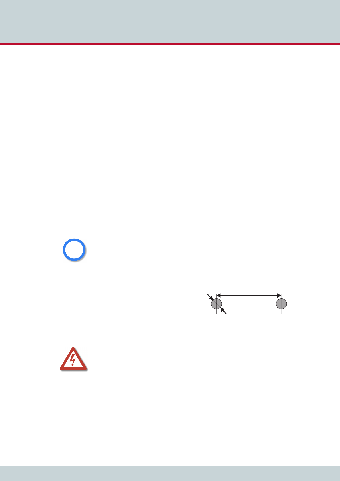
Mounting the CELLX Box
If desired, you can mount the CELLX Box on
the wall with two screws. Figure 3.1 shows
the drilling details.
Figure 3.1 Holes on the back of the CELLX Box
Immediately report any visible transport damages to customer service.
Do not use the device if it is damaged or if there are signs of malfunction. Instead, send it to
customer service or dispose of it properly (not with the public trash).
i
i
1¾"
max ¼"
screw head with max 1/8" dpth
Drilling into electrical wiring can cause drill bit and chuck to become electrically live. Do not
touch the chuck or metal housing when drilling into a wall; grasp only the insulated handle(s)
provided on the tool.
3 CELLX Box installation
Page 21
CELLX box 17.1/002
3.3 Cabling
Before you carry out any assembly or servicing tasks, please read the safety instructions given
in Chapter 2.1 on page 13.
Make sure you have the following connections in place:
Ethernet connection
FXS or ISDN connection to the telephone equipment
Power (230 V)
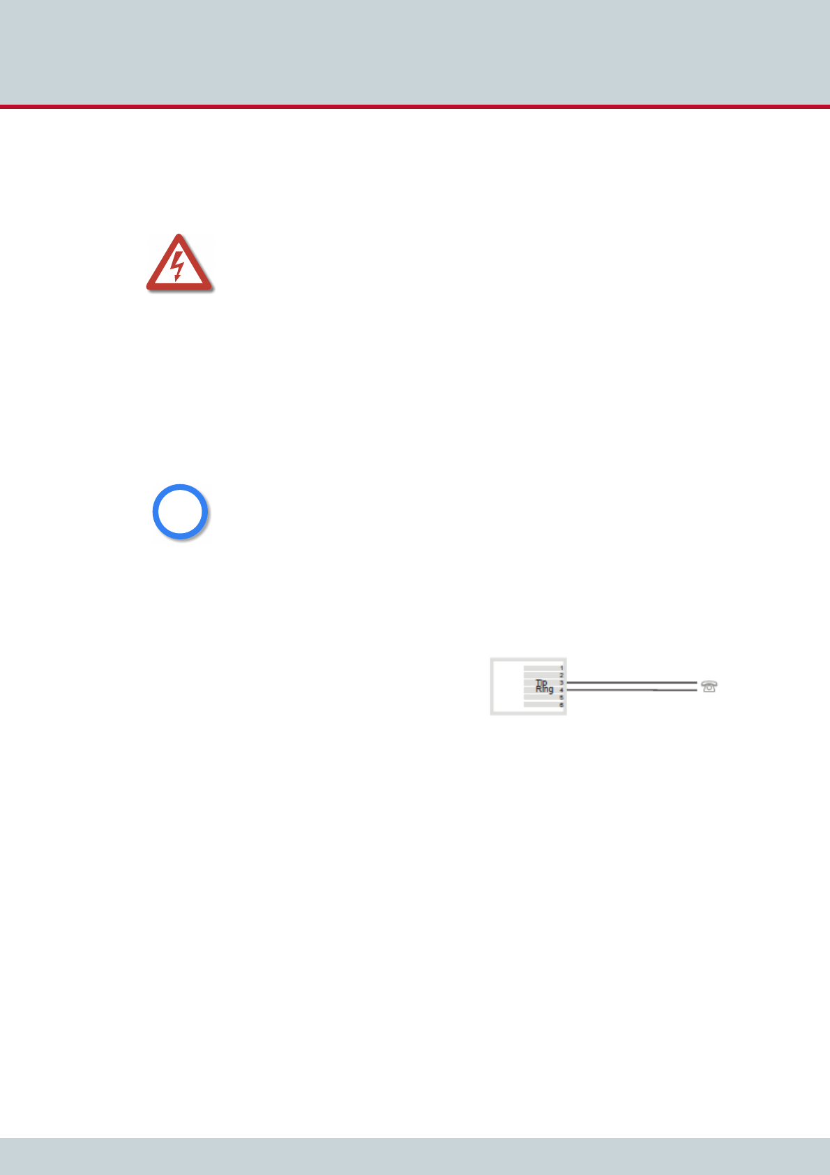
3.3.1 Analog wiring (optional for FXS)
You connect analog telephone device on the FXS ports.
When the device is properly connected, LED 6 blinks when you pick up the handset.
Figure 3.2 shows the standard pin assign-
ment for each FXS analog port.
Figure 3.2 Analog wiring scheme
3.3.2 Ethernet wiring
This step is only needed for the advanced configuration in the failover (see Chapter 1.2.2 on
page 10) and cost saving model (see Chapter 1.2.3 on page 11) scenarios, or for mainte-
nance work on the CELLX Box.
Use the three-meter cable with gray connectors to connect the CELLX Box’s Ethernet port
ETH1 to an Ethernet switch in your network.
After successful connection, the LEDs on the Ethernet switch blinks.
3.3.3 Antenna cabling
Place the antenna near a window or another place with good reception of the mobile signal.
Screw on the antenna to the SMA connector at the front of the CELLX Box.
Danger of electric shock - the power supply runs on 230 V. Use only the original power supply.
Do not use the power supply if it is damaged.
Bear in mind that telephone and WAN lines are also energized and can cause electric shocks.
Wire your system using only the cables included in the package contents. Use only proper Eth-
ernet cables.
Hold the device by its housing when you unplug it. Wall outlets can become mechanically
overloaded; do not pull on the cord.
If you do not use the supplied cable, make sure you use only a shielded Ethernet cable!
i
i

3 CELLX Box installation
Page 22
CELLX box 17.1/002
3.3.4 Power cabling
Plug the power supply directly into the outlet. Make sure the power outlet is easily accessible
at all times.
After successful connection, the CELLX Box boots – a running light indicates the initialization
process. During the boot procedure, LED1 blinks. If the software is up LED 1 is on.
Unplug the device if you do not intend to use it for an extended period of time.
3.4 LED functionality
The CELLX Box has the status LEDs described in Table 3.1.
After the successful start LED 1 is on – showing that the system of the CELLX Box is started,
LED 2–5 are on showing that calls using the mobile modules are possible, LED 6 blinks after
a pick up of a connected telephone.
Table 3.1 CELLX Box LEDs
LED Description
1 – power CELLX Box processor power:
Off: power off
On: power on
Blinking: starting.
2 – 5 mobile state State of the mobile module:
On: registered
Blinking: SIM not plugged / not registered
6 – FXS State of the FXS interfaces:
Off: no activity
ON all FXS interfaces are active
Blinking: one or more connections are active
7 – USB State of the USB interface is not supported: Always off:

4 Configuration

4 Configuration
Page 24
CELLX box 17.1/002
This chapter describes how to connect the CELLX Box to the GATE Manager and pro-
vides an introduction to the configuration. Before you begin you must be familiar
with the hardware, and the CELLX Box must be installed at the location and connect-
ed as described in Chapter 3 "CELLX Box installation" on page 19. After installation, the
CELLX Box is ready to carry out maintenance tasks using the GATE Manager, and to
configure implementation scenarios using VoIP.
4.1 Configuration tools
There are two applications available for CELLX Box remote maintenance:
Teles Quickstart
Teles GATE Manager
Quickstart’s purpose is to initially assign an IP address to your CELLX Box. All other configu-
ration and maintenance tasks are performed with the GATE Manager application.
Before you can continue, you must download the Quickstart and GATE Manager applications
from http://195.4.12.80/agw. Download the version of these two applications that best
matches your operating system. These files will be compressed zip files that your operating
system already probably already extract. Extract the files, then run the installer found in each.
4.2 Skills needed for a configuration setup
Be well versed in telecommunication technology (know the basic concepts of mobile,
FXS, VoIP, and IP technology).
Know the basics of Windows OS (handle files, install software, download files).
Handle a text editor (e.g. notpad++).
Be familiar with configuring a device with the help of config files.
Before you can start the configuration you have to do the following:
1. Assign IP address, netmask and default gateway to the CELLX Box (see Chapter 4.3
on page 24).
2. Install the GATE Manager and add the CELLX Box to the GATE Manager.
4.3 Assigning an IP address to the CELLX Box
Each computer that is to communicate with the CELLX Box requires a network connection.
Please have the following information available for connection to your network:
IP address in your local network for the CELLX Box to be configured
Netmask for the CELLX Box to be configured
Default gateway for CELLX Box to be configured
Bear in mind that the pre-configured CELLX Box’s default IP address is 192.168.1.2. If this IP
address is already being used in your local network, you must run Quickstart without a con-
nection to your local network. This can be done using a back-to-back Ethernet connection
from your computer to the CELLX Box.
i
i
4 Configuration
Page 25
CELLX box 17.1/002
Quickstart is a Windows application that helps you to configure the IP settings of your CELLX
Box quickly and conveniently without changing any network settings on your computer.
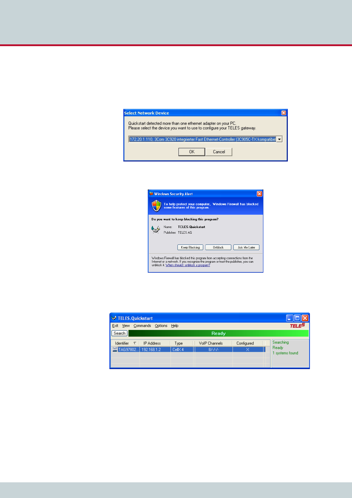
1. Launch Quickstart.
2. If Quickstart detects more than one network interface on your computer, you will be
prompted to select the LAN interface from a drop-down menu. Select the interface
that is in the same physical network as your CELLX Box.
3. If a Windows Security Alert message appears asking if Quickstart is to be blocked,
click Unblock.
4. Quickstart automatically starts scanning your network within the same Ethernet
broadcast domain. As soon as your CELLX Box has been detected you can click Stop
to stop the scanning.
On the Quickstart screen, double click on the CELLX Box Identifier to continue.
4 Configuration
Page 26
CELLX box 17.1/002
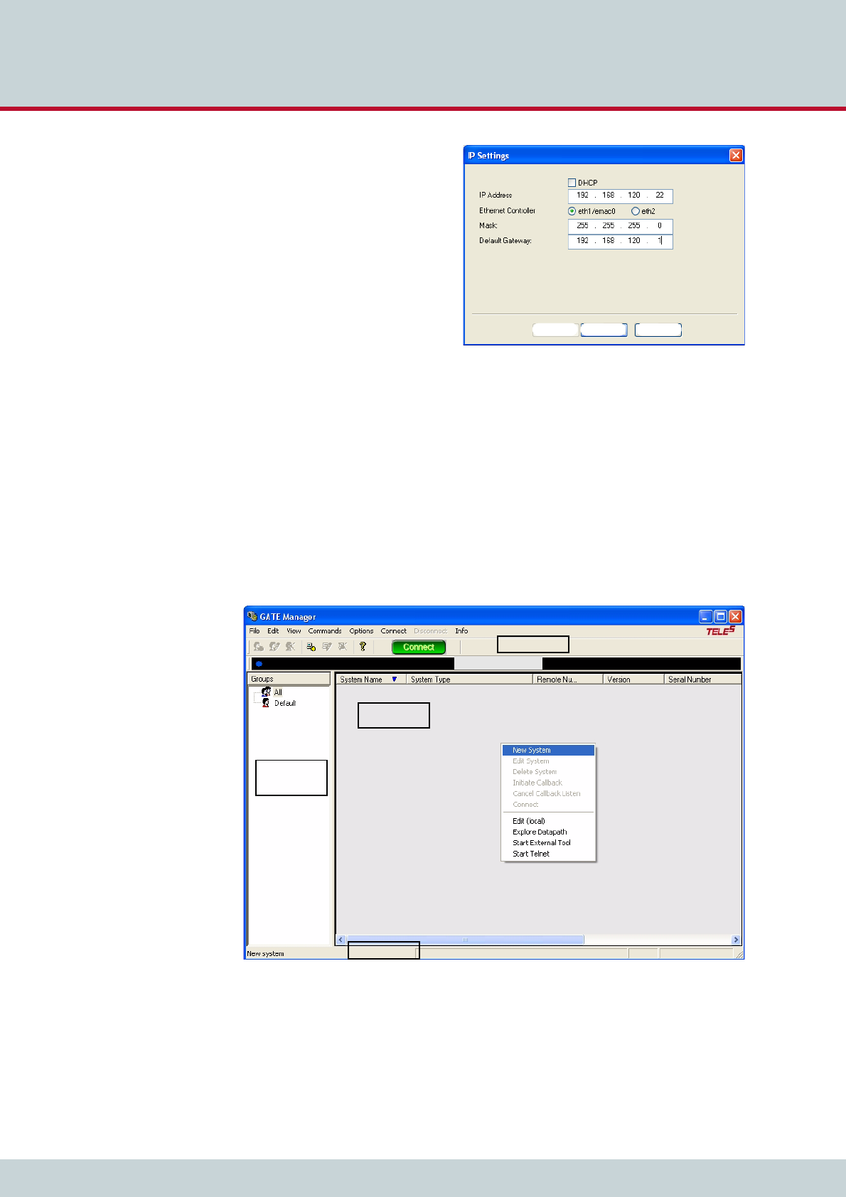
5. The IP settings window appears.
Select the Ethernet Controller
eth1/emac0 and enter the appro-
priate network settings and click
Finish to continue.
To find out your local IP settings
with the Windows command
ipconfig:
Open an CLI (Windows-key + r).
Type cmd, and press Enter. Type
ipconfig. For more information
see here. If DHCP is used, find out
which IP range is free for fixed IP
addresses (often the DHCP server is
the same as the default gateway).
6. It can take up to five minutes for the CELLX Box to reboot and apply your settings.
4.4 Connecting to the CELLX Box with GATE Manager
1. After you have assigned an IP address to your CELLX Box, assign the CELLX Box to
the GATE Manager.
2. Start the GATE Manager application and connect to your CELLX Box.
3. Select the Default group or right-click in the window on the left and select New
Group. Enter a group name in the Group field and a Comment in the next field.
Confirm with OK.
4. To enter your CELLX Box information, right-click the right pane in the GATE Manager
window and select New System from the context menu.
Back Finish Cancel
Navigation
tree
Main dialog
Status bar
Connectionbar
Toolbar
4 Configuration
Page 27
CELLX box 17.1/002
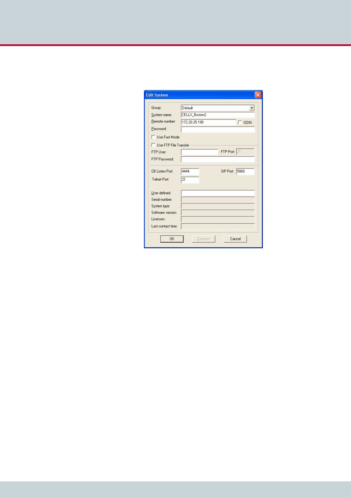
5. The Edit System dialog box will appear. Enter a meaningful name for your CELLX
Box to distinguish it from any others you plan to use. Enter the CELLX Box's IP
address. Click OK.
6. Click the green Connect button to connect to your CELLX Box.
Now you can run the maintenance tasks described in Chapter 6 "Maintenance" on page 57.
Before you go on with editing the config files, read the hints for the needed information in
Chapter 4.5. After that familiarize yourself with the config files as described in Chapter 4.6
on page 29.
4.5 Required information for further scenarios
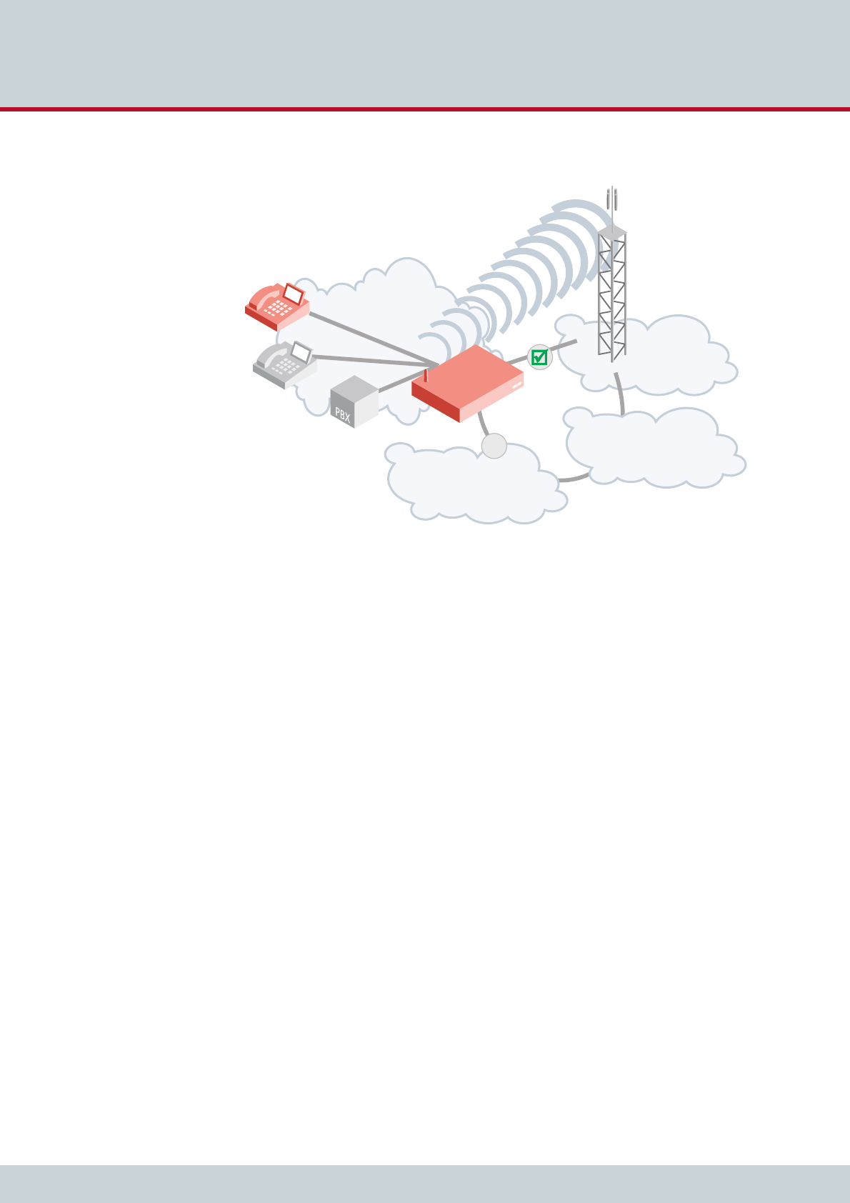
Let’s have a look at a typical deployment scenario for the CELLX Box, shown in Figure 4.1.
There are four clouds. The CELLX Box is connected to three of them:
1. the local and the telephone network with a PBX and two telephones (local network),
2. the mobile network connected with the public PSTN network, and
3. the VoIP network connected with the public PSTN network.
There are three types of hardware interfaces on the CELLX Box:
1. FXS – connects the CELLX Box with the telephones/PBX from telephone network
2. mobile – connects the CELLX Box with the mobile network
3. LAN – connects the CELLX Box with VoIP equipment (local and external VoIP devices).
The next task in the configuration is the activation of the interfaces – the configuration is al-
ready done for FXS and mobile, but some settings need to be made for VoIP.
4 Configuration
Page 28
CELLX box 17.1/002
After that, the routing between the interfaces must be configured.
Figure 4.1 General scenario for CELLX Box deployment
As shown in Figure 4.1 you need to know the following:
the local IP network the CELLX Box is integrated into: a fixed IP address, net mask and
a default gateway (already done as described in Chapter 4.3 on page 24).
the connected telephone equipment (PBX, telephones): which interface is used for
which equipment; what are the telephone numbers (internal and external) used for this
equipment?
the VoIP configuration: You need a contract with a VoIP provider who provides public
telephone numbers, a SIP proxy and a registrar. They are needed so that incoming calls
from public PSTN network can reach the CELLX Box, and from there your telephone
equipment. Your CELLX Box must be accessible for calls from the VoIP provider.
For internal VoIP you need your equipment settings.
the configuration of your mobile module providing the connection to the mobile
network.
local network
mobile
network
PSTN
VoIP
x
CELLX

4 Configuration
Page 29
CELLX box 17.1/002
Before you start with the configuration you need the information summarized in Table 4.1.
4.6 The CELLX Box config files
This chapter gives an overview of the config files of the CELLX Box. Configuration of CELLX
Boxes is managed in the files listed in Table 4.2:
These config files contain all system-specific settings and are used when the system starts.
Handle the config files as following:
1. Download the configuration file with the GATE Manager.
2. Save a copy of the configuration file.
3. Edit the configuration file on your local PC with a text editor, e.g. notepad++ (not
with a text program like MS Word).
Table 4.1 information needed to configure a CELLX Box
Information Example Description
ETH1 IP settings IP address: 172.20.25.87
Net mask: 2550.255.0.0
Default Gw: 172.20.0.78
The IP interface ETH1 is used for configura-
tion and maintenance of the CELLX Box.
DHCP is often used in local networks. The
CELLX Box works as a gateway and needs a
fixed IP configuration.
Use an IP address that is outside the DHCP
address range.
Interface definition for
FXS1 – FXS4
(if present)
Addr 10 – 13
Telephone numbers used
for the FXS interfaces:
100, 101, 102, and 103
This address is needed to send VoIP calls to
the FXS ports.
The telephone number 100 is assigned to
controller 10, 101 to controller 11 and so
on.
Interface definition for
VoIP
SIP UDP VoIP profile:
VoIP, 172.20.25.11/32;
user; passwd
Registrar profile:
VoIP. 172.20.15.12; user,
passwd
You need a SIP VoIP profile, and a Registrar
profile to get calls over the Ethernet inter-
face.
Table 4.2 Configuration files
File Function
ip.cfg This file is for the basic configuration of the Ethernet interfaces.
pabx.cfg This file is for system-specific and port-specific settings.
route.cfg This file is for call routing entries.
Changing configuration data may lead to malfunctions and/or misrouting, as well as possible
consequential damage. All changes are made at your own risk. TELES is not liable for any pos-
sible damage out of or in relation with such changes. Therefore please thoroughly check any
changes you or a third party made to your configuration.
i
i
i
i

4 Configuration
Page 30
CELLX box 17.1/002
4. Transfer the new configuration file to the CELLX Box and activate the new configura-
tion. Changes in the ip.cfg and pabx.cfg require a restart of the CELLX Box.
The configuration files are divided into sections. These sections always begin with a line entry
in square brackets. The basic required sections are listed in Table 4.3.
Comments included in these configuration files must begin with a semicolon. Comments can
also be placed at the end of the code line. Configuration files must end with an empty line.
Every section contains one or more expressions. In a expression, a keyword or value is as-
signed to a variable. Then, additional options are possible. An equal sign without spaces is
placed between keyword and variable.
As shown in Example 4.1:
the section is [System],
the expression is “PABXName=CELLX-4S_FXS-4“,
the variable in the expression is PABXName,
the value is “CELLX-4S_FXS-4“,
the rest “(1)“ of the line after the semicolon is a comment.
4.6.1 The pabx.cfg config file
The pabx.cfg file contains the definition of the controller which is needed for routing, and the
location of the log files needed for maintenance.
Only some small changes are needed in this file:
change the remote password and if necessary
DNS, and NTP adjustments, and
SMTP configuration.
Table 4.3 Required configuration file sections
Section In config file Description
[System] pabx.cfg
route.cfg
ip.cfg
Every config file must be started with this section. All previ-
ous before will ignored.
This section contains the system’s basic settings.
[eth1] ip.cfg This section contains the IP configuration for the first Ether-
net interface.
[iptables] ip.cfg This section contains the firewall settings.
[Voip:<id>] route.cfg This section contains the VoIP profile.
[Registrar:<id>] route.cfg This section contains the registrar profile used in the VoIP
profile.
Example 4.1 The first part of the pabx.cfg
[System]
PABXName=CELLX-4S_FXS-4 ;(1)

4 Configuration
Page 31
CELLX box 17.1/002
Example 4.2 shows a pabx.cfg file for the last mile scenario.
More information about the pabx.cfg is contained in the Chapter 5.2 on page 44 ff. about
the configuration.
Example 4.2 pabx.cfg for the last mile scenario
[System]
PABXName=CELLX_GSM-4_FXS-4 ; (1)
NameServer=8.8.8.8 ; (2)
NtpServer=pool.ntp.org
Timezone=CET-1CEST-2,M3.5.0/02:00:00,M10.5.0/03:00:00 ; Central European Time
ActionLog=/boot/protocol.log weekly 1200 3
TraceLog=/boot/trace.log daily 900 7
MsgLog=/boot/msg.log weekly 1200 3
Failedlog=/boot/failed.log daily 1200 7
Log=/boot/cdr.log daily 1200 7 ; (3)
StatisticTime=/boot/asr.log 00:00 11111111
Controller00=10 FXS ; (4)
Controller01=11 FXS
Controller02=12 FXS
Controller03=13 FXS
Controller04=20 GSM ; (5)
Controller05=21 GSM
Controller06=22 GSM
Controller07=23 GSM
Controller08=40 VOIP ; (6)
Controller09=41 DTMF
Subscriber00=TRANSPARENT ROUTER ANA[0,16,800,250,1500,80,12800,1,1,500,10500,10000,0,1000] NODE[0000] ; (7)
Subscriber01=TRANSPARENT ROUTER ANA[0,16,800,250,1500,80,12800,1,1,500,10500,10000,0,1000] NODE[0001]
Subscriber02=TRANSPARENT ROUTER ANA[0,16,800,250,1500,80,12800,1,1,500,10500,10000,0,1000] NODE[0002]
Subscriber03=TRANSPARENT ROUTER ANA[0,16,800,250,1500,80,12800,1,1,500,10500,10000,0,1000] NODE[0003]
Subscriber04=TRANSPARENT ROUTER GSM[0000,00000,+000000,1,1,1,SIM4,IMSI,BAND(6),TRACE(fecc)] ALARM NODE[0004]
Subscriber05=TRANSPARENT ROUTER GSM[0000,00000,+000000,1,1,1,SIM4,IMSI,BAND(6),TRACE(fecc)] ALARM NODE[0005]
Subscriber06=TRANSPARENT ROUTER GSM[0000,00000,+000000,1,1,1,SIM4,IMSI,BAND(6),TRACE(fecc)] ALARM NODE[0006]
Subscriber07=TRANSPARENT ROUTER GSM[0000,00000,+000000,1,1,1,SIM4,IMSI,BAND(6),TRACE(fecc)] ALARM NODE[0007]
Subscriber08=TRANSPARENT ROUTER ALARM CHMAX[8] NODE[0008]
Subscriber09=TRANSPARENT ROUTER CHMAX[4] DTMF[60] NODE[0009]
#SimCtrlUnitAddress=
;*END CONFIG*
(1) Definition of the CELLX Box name. This name is displayed in the GATE Manager.
(2) DNS and NTP settings of the CELLX Box. Adjust these settings to suit your needs.
(3) Path to the call detail records (CDR).
(4) Definition of the FXS controller. The controller numbers (10 … 13) are needed for the routing.
(5) Definition of the mobile controller. The controller number (20 … 23) are needed for the rout-
ing.
(6) Definition of the VoIP controller for all VoIP channel. The controller number (40) is needed for
the routing.
(7) Definition of the settings for FXS controller.

4 Configuration
Page 32
CELLX box 17.1/002
4.6.2 The ip.cfg config file
This file contains the main part of the IP configuration of the CELLX Box. Example 4.3 shows
an ip.cfg similar to the factory settings. Only the default gateway and the IP address of the
first Ethernet interface is set here. These settings are already done during the installation with
the Quickstart tool. The firewall rules are commented out. If the CELLX Box is used behind a
firewall in a local network the firewall on the CELLX Box is not needed.
Example 4.4 shows the configuration part of the ip.cfg used to configure a default gateway
with the IP address 192.168.1.1, and an additional route is set fro the network 10.1.2.0/16
using the gateway 172.20.17.125 over eth2. The IP address of the second IP interface is set
to 172.20.27.224 with the netmaks 255.255.0.0.
The section [dnsmasq] shown in Example 4.5 shows an DHCP setup for eth1. All DHCP re-
quests will be answered and the CELLX Box assign an IP address form the range 192.168.1.10
until 192.168.1.90. The default gateway is the CELLX Box on the eth1 interface and the DNS
settings from the file /etc/resolv.conf will be assigned as name server to the hosts.
Example 4.3 ip.cfg with default gateway and IP address set
[System]
DefaultGW=192.168.1.1
[eth1]
IpAddress=192.168.1.2 netmask 255.255.0.0
[iptables]
; iptables -P INPUT DROP
; iptables -P FORWARD DROP
; iptables -P OUTPUT ACCEPT
; iptables -A INPUT -d 127.0.0.1 -j ACCEPT
; iptables -A INPUT -p icmp --icmp-type echo-request -j ACCEPT
; iptables -A INPUT -p icmp --icmp-type echo-reply -j ACCEPT
; iptables -A INPUT -p tcp -i eth1 --dport 4445 -j ACCEPT
Example 4.4 ip.cfg with the IP configuration of the second IP interface
[system]
DefaultGW=192.168.1.1
Route=-net 10.1.2.0 netmask 255.255.255.0 gw 172.20.27.125 dev eth2
[eth2]
IpAddress=172.20.27.224 netmask 255.255.255.0
Example 4.5 ip.cdf with DHCP setup
[dnsmasq]
bogus-priv
filterwin2k
user=root
interface=eth1
domain=teles
dhcp-range=192.168,1.10,192.168.1.90,12h
cache-size=150
resolv-file=/etc/resolv.conf

4 Configuration
Page 33
CELLX box 17.1/002
Example 4.6 shows in addition to the examples before the settings for a default gateway on
192.168.1.1, and active NAT masquerading for the internal network 192.168.1.0/24.
The firewall blocks all incoming traffic on eth2. The exception on eth2 is icmp (for Ping re-
quests) and TCP traffic on port 4445 (for the GATE Manager) from the same subnet
(172.20.0.0/16).
For eth1 are no firewall settings defined – all traffic is allowed.
4.6.3 The route.cfg config file
The CELLX Box’s routing information is saved in the route.cfg file. Routing describes call
processing within the CELLX Box. The routing configuration is the basis for deciding on which
interface (FXS, IP, GSM) an incoming call is sent out. The route.cfg contains the sections
summarized in Table 4.4.
Example 4.6 Complete ip.cfg with default gateway and NAT
[System]
DefaultGW=192.168.1.1
[eth1]
IpAddress=192.168.1.224 netmask 255.255.0.0
[eth2]
IpAddress=172.20.27.224 netmask 255.255.255.0
[iptables]
iptables -t nat -A POSTROUTING -o eth2 -s 192.168.1.0/24 -j MASQUERADE
iptables -P INPUT -j DROP
iptables -P FORWARD -j DROP
iptables -P OUTPUT ACCEPT
iptables -A INPUT -s 172.20/16 -p tcp --dport 4445 -i eth2 -j ACCEPT
iptables -A INPUT -s 172.20/16 -p icmp -i eth2 -j ACCEPT
iptables -N block
iptables -A block -m state --state ESTABLISHED,RELATED -j ACCEPT
iptables -A block -m state --state NEW -i ! eth2 -j ACCEPT
iptables -A block -m limit -j LOG
iptables -A block -j DROP
iptables -A INPUT -j block
iptables -A FORWARD -j block
[dnsmasq]
bogus-priv
filterwin2k
user=root
interface=eth1
domain=teles
dhcp-range=192.168.1.50,192.168.1.90,12h
cache-size=150
resolv-file=/etc/resolv.conf
Table 4.4 Sections in the route.cfg file
Section Function
[System] Contains all routing entries (MapAll, Restrict, Redirect) of the default con-
figuration.
[VoIP:<name>] Contains all settings necessary for communication with the VoIP peer.
[Registrar:<name>] Contains all settings to register with the registrar.

4 Configuration
Page 34
CELLX box 17.1/002
The routing is done with three variables: Restrict, MapAll, and Redirect. The variables will
be evaluated in this order. That means the CELLX Box first analyzes all Restrict expressions
of a section, then all MapAll expressions and then all Redirect expressions. The order of the
expressions with the same variable (e.g. all MapAll expressions) is important – see the descrip-
tions of the variables.
4.6.3.1 The Restrict variable used in the route.cfg
Restrict entries are used to handle calls in a mapping based on the controller / controller
group where the calls originate. A Restrict entry can be used, for instance, to route all calls
coming from FXS directly to the mobile. If no called party number (DAD) is transmitted,
Restrict can also be used to make the call mappable, for instance for calls coming from mo-
bile.
The Restrict parameter adds a prefix to a DAD before the DAD is mapped. Restrict pa-
rameters are always handled before the MapAll parameters.
The left side of the equals sign in the Restrict parameter contains the controller number
(trunk number, and optional specific calling number (OAD)). The symbol ? may be used as a
wildcard to represent any character. The right side contains the prefix or port number that is
to be put in front of the DAD and an optional service indicator.
In the route.cfg, the list of Restrict parameters is searched from bottom to top for a
matching controller plus optional trunk number / OAD. Because the search is done bottom
up, place the more specific Restrict entries below the more general ones. Once a match
has been found, the DAD is prefixed with the contents of the <pl> variable. Then the call is
mapped.
In Example 4.7 all calls from FXS controller 10 are sent to mobile controller 20. First, the Re-
strict command adds the prefix “CO” to the DAD of the received call. This Restrict is used for
all incoming PSTN calls. Then the call is mapped. In the mapping, everything that is prefixed
Table 4.5 route.cfg: Restrict Parameters
Restrict<controller><calling number>=<pl> <sin> |
Parameter Description No. Digits Optional
<controller> Contains the controller number.
<calling number> Contains the calling number (OAD).
The symbol ? may be used as a wild-
card to represent any character.
59 together
with the con-
troller number
<pl> Stands for a virtual placeholder. The
DAD is prefixed with the contents of
this variable.
59
<sin> The service indicator variable sin re-
stricts the command to one service.
Without a sin, the Restrict com-
mand is valid for all services.
Possible service indicator values are:
00 all services (default)
01 Telephony
05 sms
06 ussd
15 Used internally for calling par-
ty manipulation
2

4 Configuration
Page 35
CELLX box 17.1/002
with “CO” is sent to controller 20 by removing the prefix and adding the controller to the
number. In addition, individually dialed digits will be converted to block dialing with the syn-
tax |…<<20.
The last line from Example 4.7 sends all calls from mobile controller 20 to FXS controller 10.
4.6.3.2 The MapAll variable used in the route.cfg
Mapping entries are necessary for routing calls. The prefix or telephone number (DAD) for
which the mapping applies is searched and the call routed according to the matching map-
ping entry.
Mapping entries begin with the keyword MapAll. They work as follows: anything on the left
of the equals sign is removed from the prefix / telephone number (DAD) that has come in and
replaced with what is on the right of the equals sign.
If, for example, the incoming DAD is 12345678 with 123456 being the trunk number 10 and
78 the extension, MapAll123456=10123456 means that 123456 is cut off the number and
10123456 is added to it. The called number is 1012345678 with 10 being the port.
MapAll123456=10 means that 123456 is cut off and 10 added. The called number is 1078
with 10 being the port.
Mappings are searched from top to bottom. Place the more specific entries above the more
general ones.
Example 4.7 Restrict
Restrict10=CO
MapAllCO=|20<<20
Restrict20=10
Table 4.6 route.cfg: map parameters
MapAll<direct>=<num> <mode>
Parameter Description No. Digits Optional
<direct> Defines the prefix or telephone number for which the
entry applies.
29
<num> Defines the routing for a call in the order given:
Destination port’s controller number
Optional VoIP profile name followed by a colon if
the call is terminated via VoIP
Optional prefix
Part of the number on the left that is transmitted
The symbol ? may be used as a wildcard to represent
any character.
The symbol . may be used as a wildcard to represent
any digit.
59
<mode> VOICE Applies for calls with the service in-
dicator voice (default).
DATA Applies for calls with the service in-
dicator data.
4 or 5 X

4 Configuration
Page 36
CELLX box 17.1/002
All mobile calls with the prefix 01555 are transmitted to the mobile controllers (20). All in-
ternational calls are sent to the VoIP provider (40) with the profile name DF. All national calls
are sent to the controller with the number 9. It is important that the mapping for international
calls is placed above the mapping for national calls. If you change the order of both mappings,
international calls would be sent to controller 9 instead of 40.
4.6.3.3 The Redirect variable used in the route.cfg
This entry facilitates alternative routing when the first destination cannot be reached or is
busy. A placeholder appears to the right of the equal sign. The routing entry (MapAll) can be
defined for the redirect using the placeholder entered.
Example 4.8 MapAll
MapAll01555=|2001555<<14
MapAll00=40DF:00
MapAll0=90
Table 4.7 route.cfg: redirect parameters
Redirect<type><num>=<redirect> <sin> <time>
Parameter Description No. Digits Optional
<type> Possible types are:
2call forwarding no answer
3call forwarding when busy
5call forwarding on no answer or busy
1
<num> Defines the number for which calls will be redirected. 59
<redirect> Defines the placeholder used in the two-target routing
entry and the number to which calls <x> will be redi-
rected.
59
<sin> The service indicator variable sin restricts the command
to a service. Without a sin, the Redirect command is val-
id for all services.
Possible service indicator values are:
01 Telephony
02 Analog services
03 X.21 services
04 Telefax group 4
05 Videotext (64 kbps)
07 Data transfer 64 kbps
08 X.25 services
09 Teletext 64
10 Mixed mode
15 Videotext (new standard)
16 Video telephony
2(X)
(Only op-
tional if
<time> is
not set. If
<time> is
set and
<sin> is
not need-
ed please
select 00
for sin.)
<time> For type 2 and 5 redirect entries, a timer (in seconds)
can be defined after the service indicator entry.
255 X

4 Configuration
Page 37
CELLX box 17.1/002
In the following example all international calls (beginning with 00) are sent to VoIP controller
40 with the provider profile PeerA. If the provider is busy, the redirect command activates the
second target mapping with the placeholder A and the call is automatically sent to another
VoIP provider e.g. with profile PeerB.
4.6.4 The route.cfg for the last mile scenario
The following config file are stored on the CELLX Box: pabx.cfg, route.cfg, and ip.cfg
Example 4.10 shows the content of the route.cfg.
Example 4.9 Redirect
MapAll00=|40PeerA:00<<24
Redirect340PeerA:=A
MapAllA=40PeerB:
Example 4.10 route.cfg for the last mile scenario for CELLX Box with FXS ports
[System]
;---------------
; Save text messages to the message.log file (1)
Restrict20=@FILE 05 ; save SMS to message.log
Restrict20=@FILE 06 ; save USSD to message.log
Restrict21=@FILE 05 ; save SMS to message.log
Restrict21=@FILE 06 ; save USSD to message.log
Restrict22=@FILE 05 ; save SMS to message.log
Restrict22=@FILE 06 ; save USSD to message.log
Restrict23=@FILE 05 ; save SMS to message.log
Restrict23=@FILE 06 ; save USSD to message.log
; inter digit collect timer is set to 3 seconds (2)
DTMFWaitDial=3
Restrict10=120 15 ; sets the internal number for FXS ports
Restrict11=121 15
Restrict12=122 15
Restrict13=123 15
; description for the ports (3)
Restrict10=fxs0
Restrict11=fxs1
Restrict12=fxs2
Restrict13=fxs3
; routing of incoming calls from GSM directly to analog ports (4)
Restrict20=10 01
Restrict21=11 01
Restrict22=12 01
Restrict23=13 01
; internal calls between the FXS ports 120 for FXS port 0
MapAllfxs?120=10 ; (5)
MapAllfxs?121=11
MapAllfxs?122=12
MapAllfxs?123=13
; all international calls from analog ports are forwarded to SIP provider (6)
MapAllfxs?00=|40PeerA:00
; all other calls from analog ports are forwarded to mobile network (7)
MapAllfxs0=|20<<24
MapAllfxs1=|21<<24
MapAllfxs2=|22<<24
MapAllfxs3=|23<<24

4 Configuration
Page 38
CELLX box 17.1/002
; SIP profile for IP phone or softphone (8)
[Voip:Phone1]
VoipDirection=IO
VoipPeerAddress=
VoipIpMask=0x00000000
VoipSignalling=1
VoipOwnUser=user
VoipOwnPwd=pwd
VoipAuth=proxy
VoipExpires=600
VoipMaxChan=2
VoipCompression=g711a g711u g729a g729b
VoipTxM=4 4 2 2
; profile for SIP provider (9)
[Voip:PeerA]
VoipDirection=IO
VoipPeerAddress= ; <ip address/name:port>
VoipIpMask=0xffffffff
VoipSignalling=1
;VoipUser=user
;VoipPwd=pwd
;VoipRegistrar=rega
VoipMaxChan=8
VoipCompression=g711a g711u g729a g729b
VoipTxM=4 4 2 2
;[Registrar:rega]
;RegId=<ip address/name:port>
;RegOwnId=<user@ip address/name>
;RegUser=user
;RegPwd=pwd
;RegSignalling=1
(1) Sends the SMS and USSD messages to the message.log file.
(2) Sets the inter-digit timer to three seconds. The CELLX Box uses this timer to convert
DTMF dialing to block dialing needs for calls to mobile and VoIP.
(3) Add the prefix fxs0 to the first FXS port, fxs1 to the second FXS port, fxs2 to the third
FXS port and fxs3 to the fourth FXS port.
(4) Sends all calls from the mobile modules to the FXS modules. Exactly from mobile
module 20 to the FXS module 10 and so on.
(5) This mapping allows connections from a FXS port to an other FXS port. A call from
fxs0, fxs1, fxs2, fxs3 to 120 will be sent to port 10 that’s the first FXS port, and so on.
(6) Sends all international calls from the FXS ports to the SIP provider PeerA.
(7) Sends all other calls from the FXS ports to the mobile modules. Number collection is
active for this mapping, to convert single-digit dialing into block dialing. The maxi-
mum number length is 24 digits.
(8) SIP profile for local SIP UAs.
(9) SIP profile for the SIP provider.
Example 4.10 route.cfg for the last mile scenario for CELLX Box with FXS ports (continued)

4 Configuration
Page 39
CELLX box 17.1/002
4.6.5 Configuration files for VoIP scenarios
These files are designed for the failover and cost saving model scenarios using VoIP connec-
tions. Possible changes of the ip.cfg are not shown in this chapter.
If you want to use either of these VoIP scenarios with the CELLX Box, rename the config files
pabx.cfg and route.cfg and adjust them to suit your needs. The adjustments are described
in more detail in Chapter 5 "Adapting the config files" on page 43. They are described in
brief here.
The pabx.cfg shown in Example 4.11 differs from the pabx.cfg shown in Example 4.2 on
page 31 in three points described below.
Example 4.11 pabx.cfg for failover and other VoIP scenarios
[System]
PABXName=CELLX_GSM-4_FXS-4 ; (1)
NameServer=8.8.8.8 ;
NtpServer=pool.ntp.org
Timezone=CET-1CEST-2,M3.5.0/02:00:00,M10.5.0/03:00:00 ; Central European Time
ActionLog=/boot/protocol.log weekly 1200 3
TraceLog=/boot/trace.log daily 900 7
MsgLog=/boot/msg.log weekly 1200 3
Failedlog=/boot/failed.log daily 1200 7
Log=/boot/cdr.log daily 1200 7 ; (3)
StatisticTime=/boot/asr.log 00:00 11111111
Controller00=10 FXS
Controller01=11 FXS
Controller02=12 FXS
Controller03=13 FXS
Controller04=20 GSM ; (2)
Controller05=20 GSM
Controller06=20 GSM
Controller07=20 GSM
Controller08=40 VOIP
Subscriber00=TRANSPARENT ROUTER ANA[0,16,800,250,1500,80,12800,1,1,500,10500,10000,0,1000]
Subscriber01=TRANSPARENT ROUTER ANA[0,16,800,250,1500,80,12800,1,1,500,10500,10000,0,1000]
Subscriber02=TRANSPARENT ROUTER ANA[0,16,800,250,1500,80,12800,1,1,500,10500,10000,0,1000]
Subscriber03=TRANSPARENT ROUTER ANA[0,16,800,250,1500,80,12800,1,1,500,10500,10000,0,1000]
Subscriber04=TRANSPARENT ROUTER GSM[0000,00000,000000,1,1,1,SIM4,BAND(6),IMSI,TRACE(fecc)] CHINSERT ALARM ; (3)
Subscriber05=TRANSPARENT ROUTER GSM[0000,00000,000000,1,1,1,SIM4,BAND(6),IMSI,TRACE(fecc)] CHINSERT ALARM
Subscriber06=TRANSPARENT ROUTER GSM[0000,00000,000000,1,1,1,SIM4,BAND(6),IMSI,TRACE(fecc)] CHINSERT ALARM
Subscriber07=TRANSPARENT ROUTER GSM[0000,00000,000000,1,1,1,SIM4,BAND(6),IMSI,TRACE(fecc)] CHINSERT ALARM
Subscriber08=TRANSPARENT ROUTER ALARM CHMAX[8]
(1) The first part is the same than in Example 4.2 on page 31.
(2) All mobile controllers have the same number (20) so that outgoing calls will be sent
to any free mobile controller.
(3) The subscriber settings for the mobile controller are enhanced with the keyword
CHINSERT. This setting is needed to route incoming calls to a particular mobile mod-
ule. With this keyword it is possible to send incoming calls from mobile controller 04
to FXS port 10 and so on.

4 Configuration
Page 40
CELLX box 17.1/002
The route.cfg shown in Example 4.12 contains far more entries than Example 4.10 on
page 37. The content is described below.
Example 4.12 voip_route.cfg for routing in failover and other VoIP scenarios
[System]
;--------------- (1)
Restrict20=@FILE 05
Restrict20=@FILE 06
; Send all email as SMS
MapAllSMS=20
DTMFWaitDial=3
; CallBack send SMS with CAL#number to intiate callback to sender and
; open second leg to number (2)
MapAllCB=20
MapAllDLA=$place
MapAllplace=10
; Send all incoming mobile calls to the respective analog port (3)
Restrict*04*20=TOFXS01
MapAllTOFXS01=10
Restrict*05*20=TOFXS02
MapAllTOFXS02=11
Restrict*06*20=TOFXS03
MapAllTOFXS03=12
Restrict*07*20=TOFXS04
MapAllTOFXS04=13
; extension 200 201 are the voip phones (4)
MapAll200=|40sp200:200<<11
MapAll201=|40sp201:201<<11
; Extension 101, 102, 103, and 104 are the analog ports (5)
MapAll100=10
MapAll101=11
MapAll102=12
MapAll103=13
; EMERGENCY (6)
; MapAll911=40PeerA:911;
; Send all other calls to VoIP Provider (7)
MapAll.=|40PeerA:?<<24
Redirect340PeerA:=A
# MapAllA=40PeerB:; fallback to a second VoIP Peer
# Redirect340PeerB:=20 ; fallback to mobile
;Failover all calls to cellular. Strip leading '1' if sent (8)
MapAllA1=20 ; Comment this line out if you are using the PeerB line above
MapAllA=20 ; Comment this line out if you are using the PeerB line above
; MapAllB1=20
; MapAllB=20
[Voip:sp200] ; (9)
VoipDirection=IO
VoipOwnUser=200
VoipOwnPwd=200pass
VoipExpires=3600
VoipAuth=www
VoipSignalling=1
VoipCompression=g711u g729
VoipTxM=2
VoipSilenceSuppression=no
VoipDtmfTransport=3
VoipRFC2833PayloadType=101

4 Configuration
Page 41
CELLX box 17.1/002
[Voip:sp201]
VoipDirection=IO
VoipOwnUser=201
VoipOwnPwd=201pass
VoipExpires=3600
VoipAuth=www
VoipSignalling=1
VoipCompression=g711u g729
VoipTxM=2
VoipSilenceSuppression=no
VoipDtmfTransport=3
VoipRFC2833PayloadType=101
[Voip:PeerA] ; (10)
VoipDirection=IO
VoipPeerAddress=1.2.3.4;; Replace with IP address supplied by your provider
VoipIpMask=0xffffffff
; Make sure this list of codecs matches those supported by your VoIP Provider
VoipCompression=g729a g711u
VoipSilenceSuppression=No
VoipSignalling=1
VoipDtmfTransport=3
VoipRFC2833PayloadType=101
VoipUser=USERNAME ; Replace with username supplied by your provider
VoipPwd=PASSWORD ; Replace with password supplied by your provider
VoipRegistrar=Registrar_PeerA
VoipIPLogging=No
VoipMediaWaitForConnect=No
; Most providers will supply multiple registration peers to increase redundancy.
; Uncomment this section to configure the gateway to accept calls from peer B
; [Voip:PeerB]
; VoipDirection=IO
; VoipPeerAddress=1.2.3.4; ;Replace with IP address supplied by your provider
; VoipIpMask=0xffffffff
;Make sure this list of codecs matches those supported by your VoIP Provider
; VoipCompression=g729a g711u;
; VoipSilenceSuppression=No
; VoipSignalling=1
; VoipDtmfTransport=3
; VoipRFC2833PayloadType=101
; VoipUser=USERNAME ; Replace with username supplied by your provider
; VoipPwd=PASSWORD ; Replace with password supplied by your provider
; VoipRegistrar=Registrar_PeerB
; VoipIPLogging=No
; VoipMediaWaitForConnect=No
[Registrar:Registrar_PeerA] (11)
RegId=1.2.3.4 ; Replace with IP address supplied by your provider
RegUser=USERNAME; Replace with username supplied by your provider
RegPwd=PASSWORD; ;Replace with password supplied by your provider
RegExpires=180
RegPing=20
(1) Sends the incoming SMS and USSD messages to the message.log file.
(2) Settings for callback initiated by an SMS (see Chapter 5.6 on page 54).
(3) Sends all incoming mobile calls to the respective FXS port.
(4) This mapping shows an example of how to reach internal VoIP clients from the FXS
ports. A VoIP profile (9) is also needed for internal VoIP clients.
(5) This mapping shows an example of how to reach the internal FXS port from a other
FXS port or a internal VoIP client.
(6) If you wish to send emergency calls to a special port (e.g. over the VoIP profile PeerA
only) comment out this line.
(7) This mapping send all other calls out to the VoIP profile PeerA. If Peer A is not avail-
able the calls will be redirected.
Example 4.12 voip_route.cfg for routing in failover and other VoIP scenarios (continued)

4 Configuration
Page 42
CELLX box 17.1/002
(8) This mapping receive VoIP calls redirected and send them out to mobile.
(9) This is an example of a VoIP profile for local devices. Adjust password, username and
the compression codec list to suit your needs.
(10) This is an example of an external VoIP profile. Adjust Peer IP, password, username
and the compressions list to the values given by the SIP provider.
(11) This is an example of an registrar profile. Adjust IP address, password, and username
to the values given by the SIP provider.

5 Adapting the config files
5 Adapting the config files
Page 44
CELLX box 17.1/002
This chapter describes some frequent configuration scenarios.
5.1 Editing the config files
To edit configuration files, connect to the CELLX Box using the GATE Manager, as described
in Chapter 4.4 Connecting to the CELLX Box with GATE Manager on page 26.
Change to Directory view by selecting Directory in the menu in the left pane.
GATE Manager lists all of the files on your CELLX Box. The configuration files are shown in
the upper left quarter.
To change a configuration file, right-click the file name and select Download from System.
This copies the file to your computer. CELLX Box configuration files are standard text files and
can be edited with a text editor, such as Notepad++.
When you have completed the changes, save the file and close the editor. To send the new
file back to your CELLX Box, right-click in the GATE Manager window and select Upload to
System. Then select the changed version of the configuration file you want to send back to
the CELLX Box.
If you upload a new version of the route.cfg configuration file, GATE Manager will ask if
you want to activate the new configuration. Confirm with OK.
Changes in the pabx.cfg or ip.cfg require a restart of the CELLX Box. Close the GATE Man-
ager.
Note: The CELLX Box can take up to 3 minutes to reboot and apply your settings.
5.2 Securing the CELLX Box
To enhance the security of your CELLX Box, set a password for the GATE Manager and if the
CELLX Box is used directly with the Internet, configure the firewall.
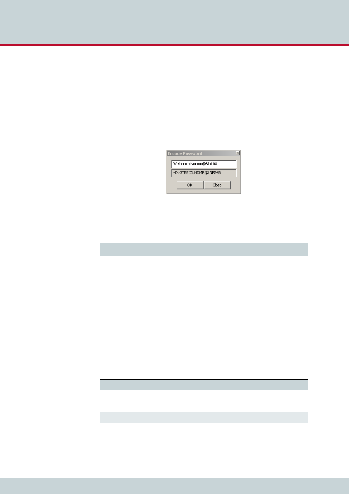
5 Adapting the config files
Page 45
CELLX box 17.1/002
5.2.1 Setting the password for the GATE Manager
The CELLX Box comes with no password set for GATE Manager access. If you do not define
a password, access to the system via GATE Manager takes place without one, and FTP access
takes place with the default password tcs-ag.
The password is set with the command RemotePassword=<password> in the [system] sec-
tion of the pabx.cfg. The value <password> contains the encrypted text of the password.
Define the encrypted text with the GATE Manager as follows:
1. Open the GATE Manager,
2. Select the menu Edit | Encode Password…
3. Enter the password in clear text in the Encode Password box and click OK.
4. In the screenshot above, the clear text password is Weihnachtsmann@Bln. The
encoded password is vDLGTEBIZUNDMR@fNP54B.
5. Enter the encoded password as shown in Example 5.1.
6. Transfer the pabx.cfg to the CELLX Box using the GATE Manager. After the file has
been transferred reboot the CELLX Box. The system can than be accessed only with
the correct password. Don’t forget to memorize it!
5.2.2 Adjusting the firewall setting
If the CELLX Box is running in a DMZ (Demilitarized zone (computing)) the firewall must be
activated in the ip.cfg (see Chapter 2.2.15 on page -16).
The firewall used on CELLX Box is iptables. The documentation is freely available on the inter-
net. Only the table filter is used in the ip.cfg. Outgoing traffic is allowed unless otherwise
specified. Incoming and forwarded traffic is dropped unless otherwise specified.
The options used in Example 5.2 are listed in Table 5.1.
Example 5.1 pabx.cfg with an encoded password
RemotePassword=vDLGTEBIZUNDMR@fNP54B
Table 5.1 iptable options used in Example 5.2
Option Description
-P INPUT DROP Policy for the chain (INPUT, OUTPUT, FORWARD) used if no other filter rule
is defined. The action used in this case is DROP. For the other rules, use the
action ACCEPT.
-A INPUT Policy added to the INPUT chain.
-d <destination IP> This policy is only true for packets with the given destination IP address.

5 Adapting the config files
Page 46
CELLX box 17.1/002
Example 5.2 shows the firewall rules activated in the ip.cfg.
With these rules, outgoing traffic is allowed, incoming traffic is only possible in the local in-
terfaces. The following protocols are allowed for incoming traffic: icmp (ping), DNS forward-
ing, NTP, H.225, SIP, and RTP (used for VoIP), and GATE Manager.
5.3 VoIP configuration
The CELLX Box supports VoIP for local and public calls. Because the circumstances are not
known, a special configuration is needed here. The configuration is divided into the following
main parts:
configuration of the settings given by your VoIP provider (VoIP profile)
configuration of the settings for local VoIP devices (Registrar profile)
call routing for incoming and outgoing calls (mappings).
-s <source IP> This policy is only true for packets from the given source IP address.
This option is not used in the example but if the source is known use this op-
tion for more security.
-i <interface> This policy is only true for packages used the given IP interface. (lo – local
loop interface, eth1 – the first IP interface)
-p <protocol> This policy is only true for the given IP protocol (UDP, TCP).
--dport <portnum> This policy is only true for the given protocol number. Sometimes the defini-
tion in /etc/protocols will be used instead. This option can only be used
together with the -p option.
-j ACCEPT Defines the action that is carried out if the packet matches the rule.
Table 5.1 iptable options used in Example 5.2
Option Description
Example 5.2 Basic firewall settings for eth1
[iptables]
iptables -P INPUT DROP
iptables -P FORWARD DROP
iptables -P OUTPUT ACCEPT
iptables -A INPUT -d 127.0.0.1 -j ACCEPT
iptables -A INPUT -p icmp --icmp-type echo-request -j ACCEPT
iptables -A INPUT -p icmp --icmp-type echo-reply -j ACCEPT
; iptables -A INPUT -p tcp -i eth1 --dport ftp -j ACCEPT
; iptables -A INPUT -p tcp -i eth1 --dport http -j ACCEPT
; iptables -A INPUT -p tcp -i eth1 --dport smtp -j ACCEPT
iptables -A INPUT -p udp -i eth1 --dport 53 -j ACCEPT ; DNS forward
iptables -A INPUT -p udp -i eth1 --dport ntp -j ACCEPT
; iptables -A INPUT -p udp -i eth1 --dport snmp -j ACCEPT
iptables -A INPUT -p udp -i eth1 --dport 1719 -j ACCEPT ; H.225 (UDP)
iptables -A INPUT -p tcp -i eth1 --dport 1720 -j ACCEPT ; H.225 (TCP)
iptables -A INPUT -p tcp -i eth1 --dport 4445 -j ACCEPT ; GATE Manager
iptables -A INPUT -p udp -i eth1 --dport 5060 -j ACCEPT ; SIP
iptables -A INPUT -p udp -i eth1 --dport 29000-29120 -j ACCEPT ; RTP

5 Adapting the config files
Page 47
CELLX box 17.1/002
5.3.1 VoIP settings for a public VoIP provider
If a public VoIP provider is used for incoming and outgoing calls the following configuration
is needed:
a) the CELLX Box must be reachable for incoming SIP and RTP IP traffic. This configuration
depends on the network configuration and the VoIP provider.
b) a SIP profile is needed for the VoIP provider, so that calls can be sent out. The SIP profile
name is used in the call routing.
c) a Registrar profile is needed to register on the VoIP provider, so that calls can be re-
ceived from the public telephone network. The name of the Registrar profile is refer-
enced in the SIP profile.
d) a call routing configuration is needed to send calls out to the VoIP provider and to send
calls from the VoIP provider to the telephones connected on the FXS ports.
5.3.1.1 VoIP profile for the provider
Example 5.3 shows a SIP profile configured in the route.cfg file.
Example 5.3 is explained in Table 5.2.
Example 5.3 A SIP profile for PeerA
[Voip:PeerA]
VoipDirection=IO
VoipPeerAddress=1.2.3.4 ; Replace with IP address supplied by your provider
VoipIpMask=0xffffffff
VoipCompression=g729a g711u
VoipSilenceSuppression=No
VoipSignalling=1
VoipDtmfTransport=3
VoipRFC2833PayloadType=101
VoipUser=USERNAME ; Replace with username supplied by your provider
VoipPwd=PASSWORD ; Replace with password supplied by your provider
VoipRegistrar=Registrar_PeerA
VoipIPLogging=No
VoipMediaWaitForConnect=No
Table 5.2 Explanation of the SIP profile in Example 5.3
Line in the example Explanation
VoipDirection=IO The VoIP profile used for incoming and outgoing VoIP connec-
tions.
VoipPeerAddress= This variable contains the hostname or IP address of your provid-
er’s SIP proxy.
If you enter a hostname, make sure that a NameServer is con-
figured in the pabx.cfg. If you change the name server, the
CELLX Box has to be rebooted.
VoipIpMask=0xffffffff The subnetmask is used to determine the size of the IP address
range for incoming traffic. This traffic is accepted only from the
defined peer VoipPeerAddress.
VoipOwnDisplay= Enter the username or telephone number displayed to the B par-
ty.

5 Adapting the config files
Page 48
CELLX box 17.1/002
Adjust the following variables:
VoipPeerAddress – domain name or address of the VoIP provider.
VoipUser – your username for the provider.
VoipPwd – your password for the provider.
VoipOwnDisplay – name displayed to the B party.
VoipRegistrar – name of the registrar profile defined for the VoIP provider.
VoipCompression= Defines the values of compression codecs used for the connec-
tion. Order the codecs according to your preference. The follow-
ing values are defined: g711a, g711u, g729a, g729b, g72616,
g72624, g72632, g728, g723, g723L, gsm, ccd, gnx64
VoipSilenceSuppression=No Silence suppression, CNG (comfort noise generation) and VAD
(voice activity detection) is inactive.
VoipSignalling=1 SIP with UDP is active. To activate SIP with TCP, enter 2.
The following settings are set in the pabx.cfg. Adjust them if
required:
SipPort=5060
VoipRtpPort=29000
VoipRtpPortSpacing=2
VoipDtmfTransport=3 Defines the transport of DTMF information. DTMF is taken from
audio stream and relayed to remote as per RFC2833, while rtp
data with silence is sent.
VoipRFC2833PayloadType=101 Defines the DTMF payload type as 101.
VoipUser=USERNAME Sets the VoIP username given from the VoIP provider.
VoipPwd=PASSWORD Sets the VoIP password given from the VoIP provider.
VoipRegistrar=Registrar_PeerA Points to the registrar profile used with this VoIP profile.
VoipIPLogging=No IP addresses will not be written to the CDR records. Set the value
to Yes if this feature is needed.
VoipMediaWaitForConnect=No RTP data is transmitted immediately after negotiation for RTP.
Early media is activated; SDP is sent with 183 or 180.
VoipUseSTUN=No Set the value to Yes if STUN is used.
In addition set these variables in the pabx.cfg:
StunServerAddress=<stun-server>:<port>
StunServerPollInterval=<interval>
Table 5.2 Explanation of the SIP profile in Example 5.3 (continued)
Line in the example Explanation

5 Adapting the config files
Page 49
CELLX box 17.1/002
5.3.1.2 Registrar profile defined for the provider
The registrar profile is needed to register your CELLX Box, so that your SIP provider will find
you and send calls to your CELLX Box. Example 5.4 shows a registrar profile configured in the
route.cfg.
Example 5.4 is explained in Table 5.3.
Adjust the following variables:
RegID – the IP address of the registrar.
RegUser – your username for the provider.
RegPwd – your password for the provider.
RegOwnId – your content of the FROM field.
Example 5.4 A registrar profile Registrar_PeerA
[Registrar:Registrar_PeerA]
RegId=1.2.3.4 ; Replace with IP address supplied by your provider
RegUser=USERNAME ; Replace with username supplied by your provider
RegPwd=PASSWORD ; Replace with password supplied by your provider
RegExpires=180
RegPing=20
RegOwnId=<user@ip_address_or_name>
Table 5.3 Explanation of the registrar profile in Example 5.4
Line in the example Explanation
RegId= Enter the host name or IP address of your SIP provider. Following the IP ad-
dress, insert the optional port number used, e.g. 1.2.3.4:5060.
RegUser= Enter the VoIP username given by your VoIP provider.
RegPwd= Enter the VoIP password given by your VoIP provider.
RegExpires Change the live time of a registration if another value is given by the provid-
er.
RegPing= The CELLX Box sends an empty UDP packet to the registrar’s IP address in the
given interval. Changes the time between these packages if other values are
given by the provider.
RegOwnId= The CELLX Box use this ID in the FROM field of the SIP signaling.

5 Adapting the config files
Page 50
CELLX box 17.1/002
5.3.1.3 Call routing for outgoing calls to the provider
The call routing in the route.cfg tells the CELLX Box which calls are sent to the VoIP provid-
er. The call routing is configured with the MapAll parameter (see Table 4.6 on page 35).
The first lines in Example 5.5 defines a placeholder for the FXS ports. The last line send all calls
from an FXS port that has dialed an international number (that starts with 00) out to the VoIP
profile PeerA. Table 5.4 explains Example 5.5 in more detail.
The following adjustments are possible:
Adjust the call routing in the line MapAllfxs?00=|40PeerA:00
Comment out the line and adjust the prefix to your needs. The following mapping sent
all calls to the international prefix from Germany to VoIP PeerA:
MapAllfxs?0049=|40PeerA:0049
The international prefix 00 is changed to 0049 in this case.
To sent incoming VoIP calls to the FXS ports use the following call routing:
MapAll<number0>=10
MapAll<number1>=11
MapAll<number2>=12
MapAll<number3>=13
Replace the <number0…3> with the telephone numbers assigned to your FXS ports by
the VoIP carrier. 10, 11, 12 and 13 are the FXS ports of the CELLX Box.
Example 5.5 Call routing for VoIP calls on the CELLX Box
; routing of incoming calls from the analog devices
Restrict10=fxs0
Restrict11=fxs1
Restrict12=fxs2
Restrict13=fxs3
;...
; all international calls from analog ports are forwarded to SIP provider
MapAllfxs?00=|40PeerA:00
Table 5.4 Explanation of the routing in Example 5.5
Configuration Description
MapAll Variable for the call routing.
fxs0, fxs1, fxs2, fxs3 That are placeholder for the FXS ports.
fxs?00 A call from any FXS port with a destination address that starts with 00.
00 Prefix of international dialing codes.
= The outgoing mapping is entered after the equal sign.
|Collect single dialed digits to a block dialed destination address.
40 The call is sent to the VoIP port with the number 40.
PeerA: The VoIP profile PeerA is used for the call.

5 Adapting the config files
Page 51
CELLX box 17.1/002
5.3.2 VoIP settings for local SIP UA
The configuration of local SIP user agents (UA, such as softphones or SIP phones) is nearly the
same than the configuration for the VoIP provider. If a local SIP device is used for incoming
and outgoing calls to the FXS or mobile ports the following configuration is needed:
a) The CELLX Box works as registrar for the SIP devices, so a VoIP profile is needed.
b) A call routing configuration is needed to send calls from the local SIP device to the other
devices (FXS, mobile) and from the other devices (FXS, mobile) to the local SIP device.
5.3.2.1 VoIP profile for the local SIP UAs
The CELLX Box works as registrar for the local SIP UA. So you need a VoIP profile for every SIP
UA, as shown in Example 5.6.
The important parameters are as follows:
[Voip:sp200] – the name of the profile (here sp200). This name is used in the
mapping. The value is random. For the next UA, change this value.
VoipOwnUser – the username (here 200). This name must be set in the SIP UA
configuration. The value is random.
VoipOwnPwd – the password (here 200pass). This password must be set in the SIP UA
configuration. The value is random.
VoipDadIn – this variable sets the VoIP dad prefix sip0 for all incoming calls. This prefix
will be used later in the call routing.
Example 5.6 VoIP profile for registering local SIP UAs
[Voip:sp200]
VoipDirection=IO
VoipOwnUser=200
VoipOwnPwd=200pass
VoipExpires=3600
VoipAuth=www
VoipSignalling=1
VoipCompression=g711u g729
VoipTxM=2
VoipSilenceSuppression=no
VoipDtmfTransport=3
VoipRFC2833PayloadType=101
VoipDadIn=sip0

5 Adapting the config files
Page 52
CELLX box 17.1/002
5.3.2.2 Call routing for calls to and from the local SIP device
Call routing sends the calls from the ports of the CELLX Box to the local SIP UAs and from the
local SIP UAs to the devices on the ports of the CELLX Box. Please see Example 5.7.
The first two mappings are used to allow connections from the FXS ports to the SIP UAs. In
Example 5.7 two SIP UAs are defined, one with the extension 200 using the VoIP profile
sp200 and one with the extension 201 with the same VoIp profile. The dialed digits from the
FXS ports is converted to block dialing using | at the begin.
The entries that follow are used to send the calls from the SIP UAs to the FXS lines. The ex-
tensions for the first FXS line is 100. The extension for the second FXS line is 101, and so on.
All international calls from SIP with the prefix 00 will be sent to the VoIP profile PeerA. All
other calls from the SIP UAs will be sent out to the mobile controller.
5.4 Rerouting or failover
If a port is not available e.g. in the failover scenario (see Chapter 1.2.2 on page 10) the calls
may be sent to an alternative route. This alternative routing is configured by the redirect pa-
rameter (see Table 4.7 on page 36). Example 5.8 shows the rerouting for calls to the public
VoIP profile PeerA over the mobile ports 20.
First, all calls that receive a busy response from PeerA will be redirected to the symbolic num-
ber A.
Then, all calls to the symbolic number A will be routed to the mobile ports (20).
Example 5.7 Call routing for calls from the FXS ports to the local SIP UAs
; send extension dialing to softphones from fxs ports
MapAllfxs?200=|40sp200:200
MapAllfxs?201=|40sp201:201
;calls from UAs to FXS
MapAllsip?100=10
MapAllsip?101=11
MapAllsip?102=12
MapAllsip?103=13
;calls from UAs to SIP-Provider
MapAllsip?00=|40PeerA:00
;all others calls from UAs to mobile
MapAllsip0=|20<<24
MapAllsip1=|21<<24
;…
Example 5.8 Rerouting the calls using the PeerA VoIP profile to the mobile ports
Redirect340PeerA:=A
MapAllA=20

5 Adapting the config files
Page 53
CELLX box 17.1/002
It is also possible to activate a rerouting from one VoIP provider to the next. If the first VoIP
provider is not available the calls will be routed to the next VoIP provider. You need two VoIP
providers in this case, configured as described in Chapter 5.3.1 on page 47. In Example 5.9
these will be PeerA for the first VoIP provider and PeerB for the second VoIP provider. If the
second provider is also not available the call will be routed to mobile.
5.5 Cost saving routing
This is a mapping similar to the rerouting described in the previous section. If it is possible to
reach a destination over different ports or numbers, create a route on the cheapest way first.
The next way is reachable with a rerouting.
Example 5.10 sends the calls from FXS to the destination 541867530 directly to the mobile
ports, not with the default routing in the next line to VoIP like all other normal traffic. The
first line overrides the default routing and sends the call directly to the mobile port instead of
the normal VoIP provider.
Example 5.9 Rerouting the calls using the PeerA VoIP profile to the mobile ports
Redirect340PeerA:=A
MapAllA=40PeerB:
Redirect340PeerB:=B
MappAllB=20
Example 5.10 Cost saving routing
MapAllFXS541867530=20541867530
MapAllFXS?=|40PeerA:?<<20
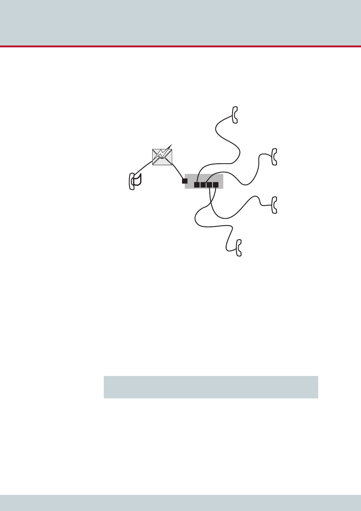
5 Adapting the config files
Page 54
CELLX box 17.1/002
5.6 Callback initiated by SMS
Callback offers the possibility of cost saving and central billing. Figure 5.1 shows how SMS
callback can be used.
Figure 5.1 SMS callback example
Figure 5.1 shows a CELLX Box in the center with four FXS ports and connected telephones.
The telephone on FXS1 has the number 100 and so on. The mobile module 04 has the num-
ber 222444555.
The mobile phone with the number 222333444 sends a text message (SMS) to 222444555
requesting a callback from the telephone on FXS1 with the number 100. The text of the mes-
sage is “CAL#100”. The SMS is received by the mobile module 04 and a call is initiated to
222333444 and 100 from there.
Check that the path to the message log file (msg.log) is set in the pabx.cfg as shown in
Example 5.11
100 (FXS1)
101 (FXS2)
102 (FXS3)
103 (FXS4)
SMS: CAL#100
222333444 mobile
222444555
CELLX
Example 5.11 Activation of the message log in pabx.cfg
; …
MsgLog=/boot/msg.log weekly 600 6
; …

5 Adapting the config files
Page 55
CELLX box 17.1/002
In the route.cfg set the entries shown in Example 5.12.
The settings in Example 5.12 are explained in Table 5.5. If the internal numbering plan differs
adjust the last mappings (MapAllplace*).
5.7 Mail to SMS
The CELLX Box converts e-mail messages to SMS messages. Send an e-mail to your CELLX Box
via SMTP using any e-mail client. The CELLX Box converts the e-mail into an SMS message
and sends it to the mobile network.
Configure the mail settings in the pabx.cfg as shown in Example 5.13.
Example 5.12 Settings in the route.cfg for SMS callback
; …
; send the incoming SMS to the msg.log file
Restrict20=@File 05
; …
; send SMS with CAL#number to intiate callback to sender and open a leg to number
MapAllCB=20
MapAllDLA=$place
MapAllplace100=10
MapAllplace101=11
MapAllplace102=12
MapAllplace103=13
Table 5.5 Explanation of the routing in Example 5.12
Configuration Explanation
Restrict20=@File 05 This entry is already set in the route.cfg. It writes the incoming SMS
to the file defined by MsgLog in the pabx.cfg.
MapAllCB=20 The callback is done on CMDA port 20.
MapAllDLA=$place A jump to the call routing is initialized. ’place’ is used as the flag for all
callback routes.
MapAllplace100=10 Sets the routing to the phone number 100 set in the SMS after CAL#.
Example 5.12 defines only routes to the internal FXS ports – routes to
mobile or VoIP are not defined (because of security/costs risks).
Example 5.13 Mail server settings in the pabx.cfg
[System]
; …
[Mail]
SmtpServer=1.2.3.4
MailUserOut=your-name@smtp.com
MailPwdOut=your-password-at-smtp
;MailRcpt=cellx@yourcompany.com
MailFrom=cellx.yourcompany.com
MaxMailsToHost=1
MailMaxIncomingClients=4
MailRcvMax=50
MailRcptMax=1
MailSMSSendStatus=Yes
MailSMSDeliveryConfirmation=No
; …

5 Adapting the config files
Page 56
CELLX box 17.1/002
The settings in Example 5.13 are explained in Table 5.6. Adjust the IP address of the SmtpS-
erver. Set the username and password for the SMTP server if needed (MailUserOut and
MailPwdOut). Set the MailRcpt and the MailFrom variable.
Check that the mapping for SMS to the mobile ports is set in the route.cfg as shown in
Example 5.14.
Table 5.6 Explanation of the routing in Example 5.12
Configuration Explanation
SmtpServer=1.2.3.4 Replace 1.2.3.4 with the IP address of your SMTP server. This
server will be used to send out status mails from the CELLX
Box.
MailUserOut=your-name@smtp.com If the SMTP server needs authentication, fill in the user name
here.
MailPwdOut=your-password-at-smtp If the SMTP server needs authentication, fill in the password
here.
MailRcpt=cellx@yourcompany.com Completes the e-mail recipient information for the mail to
SMS scenario. This feature is not needed here.
MailFrom=cellx.yourcompany.com The confirmation mails will be sent from this e-mail address
in the format OAD@celly.yourcompany.com. OAD is
the number of the mobile module.
MaxMailsToHost=1 Defines the maximum number of e-mail messages which can
be sent as SMS messages simultaneously.
MailMaxIncomingClients=4 Defines the maximum number of mail clients that can access
the SMTP server simultaneously.
MailRcvMax=50 Defines the maximum number of incoming e-mails queued
for transmission via SMS.
MailRcptMax=1 Defines the number of "RCPT TO" entries in e-mails. This
feature is not needed here.
MailSMSSendStatus=Yes An e-mail is sent to confirm that the SMS has been sent. If
you don’t need this confirmation mail, set the value to No.
MailSMSDeliveryConfirmation=No No e-mail is sent from mobile network to confirm delivery.
Example 5.14 Mapping for the SMS in route.cfg
; …
MapAllSMS=20
; …

6 Maintenance

6 Maintenance
Page 58
CELLX box 17.1/002
This chapter describes the CDR and trace maintenance tasks.
6.1 Call detail records (CDR)
The CELLX Box writes call detail records of all connections to the system memory. The path
to the file (/boot/cdr.log) is set in the pabx.cfg (see Example 4.2 on page 31). All calls
without a connection will be written to the /boot/failed.log.
New entries are always added to the end of the file. Example 6.1 shows a sample log file.
Each line represents a call with the information listed in Table 6.1.
Call Detail Records are intended for analysis of the CELLX Box’s activity only. They are not de-
signed to be used for billing purposes, as the times they record may not be exact.
i
i
Example 6.1 Sample cdr.log file
C1,25.11.09-10:16:20,25.11.09-10:16:27,9,111,,,,,0102,7,1f,0,,3663,10,,,
C1,25.11.09-10:35:16,25.11.09-10:35:26,9,111,,,,,0102,10,1f,0,3,38922,14,,,
C1,25.11.09-10:38:30,25.11.09-10:38:41,9,111,,,,,0102,11,90,0,3,38922,14,,,
Table 6.1 Entries of the cdr.log file informations separated by commas
Column Description
0Version
1Start time (format DD.MM.YY-hh.mm.ss)
2 End time (format DD.MM.YY-hh.mm.ss)
3Source. The following format applies: [node number:automatically set internal chan-
nel number]
4 Destination. The following format applies: [node number:automatically set internal
channel number]
5IMSI (optional)
6 IP logging signaling: RTP (optional)
7Audio codec used (optional)
8 Frame size (optional)
9Service indicator (see Table 6.2 on page 59)
10 Call duration
11 Cause values (see Table 6.3 on page 60)
12 Charge from the public line (in units)
13 Charge generated from the system (in units) (if configured)

6 Maintenance
Page 59
CELLX box 17.1/002
The service indicator listed in the call log and missed calls list describes the type of connection
as a four digit hexadecimal number. The coding is conducted according to the 1TR6 standard
are listed in Table 6.2.
With recording of files, system maintenance increases. You have to be sure to download or
delete files and ensure that there is enough space left on the CELLX Box.
6.1.1 Activating peer data for VoIP calls
To generate a VoIP-call CDR entry that includes IP addresses for the remote device’s signaling
and voice data, audio codec and frame size, the entry VoipIpLogging=Yes must be included
in the VoIP profile. If the entry also contains the mobile controller’s IMSI, it will appear before
the IP addresses.
14 Cell ID (if mobile call)
15 RSSI (if mobile call)
Table 6.1 Entries of the cdr.log file informations separated by commas
Column Description
Table 6.2 Defined values for service indicators
Service Indicator Definition
0101 ISDN telephony 3.1 kHz
0102 analog telephony
0103 ISDN telephony 7 kHz
0200 Fax group 2
0202 Fax group 3
0203 Data via modem
0400 Telefax group 4
0500 SMS or BTX (64 kbps)
0700 Data transfer 64 kbps
07… Bit rate adaptation
1001 Video telephone – audio 3.1 kHz
1002 Video telephone – audio 7 kHz
1003 Video telephone – video

6 Maintenance
Page 60
CELLX box 17.1/002
The CDR entry in Example 6.2 includes IP addresses for signaling and voice data, audio codec
and frame size.
6.1.2 CDRs for callback and two stage calls
In the case of CDR entries for two-stage dialing/callback calls, the beginning and ending times
for the first call leg is always used as the call time. The call time in seconds appears first for
the first leg, followed by a slash and the connection time for the second leg, as shown in Ex-
ample 6.3.
6.1.3 Specific cause values
The CELLX Box will generate cause values that represent an event, such as exceeding a de-
fined limit. They are listed in Table 6.3.
Example 6.2 Sample cdr.log file with VoIP information
C1,24.11.09-16:52:20,24.11.09-
16:52:22,401419,9777,,172.20.25.103:172.20.25.103,G711a,20,0101,2,10,0,,,11
Example 6.3 Sample cdr.log file for callback and two-stage calls
C1,24.11.09-17:15:29,24.11.09-
17:15:57,[0002:01]CB,[0008:01]DLA,,172.20.25.103:172.20.25.103,G711a,20,0102,28/
3,90,0,,,
Table 6.3 Specific cause values
Cause Value Description
0a One of the following limits has been reached:
Unit limit defined in the port’s subscriber line
Unit limit per SIM assignment via CELLX Box
0b Maximum call duration assigned via CELLX Box has been reached
0c Maximum call duration based on mapping entry settings has been reached
0d Maximum number of minutes per SIM assignment via CELLX Box has been
reached
10, 1f Normal call termination (disconnected by calling party)

6 Maintenance
Page 61
CELLX box 17.1/002
6.1.4 Missed calls list
All incoming calls that are not connected can be recorded in a list to facilitate return calls (/
boot/failed.log). Each line represents an incoming call that was not accepted, with the
information separated by commas, as listed in Table 6.4.
Example 6.4 shows a sample failed.log file.
The reason the connection could not be established is specified using DSS1 codes:
91 – (user busy)
ff – call not answered (disconnected by calling party)
Table 6.4 Entries in the failed.log file separated by commas
Column Description
0Version
1Start time (format DD.MM.YY-hh.mm.ss)
2 Source. The following format applies: [node number:automatically set internal chan-
nel number]
3Destination. The following format applies: [node number:automatically set internal
channel number]
4IMSI
5IP logging signaling: RTP
6 Audio codec used
7Frame size
8 Service indicator
9Cause values
10 Call duration (if the call does not result in an Alerting, the entry will be -1)
11 Number of call attempts
12 Cell ID
13 RSSI
Example 6.4 Sample failed.log
F1,24.11.09-16:13:08,[0006:01]IN,[0008:01]GSM,123456789123456,,,,0101,91,-1,1,34193,9
F1,24.11.09-16:33:34,[0006:01]IN,[0008:01]GSM,123456789123456,,,,0101,91,-1,1,34193,12
F1,24.11.09-16:35:19,[0006:01]IN,[0008:01]GSM,123456789123456,,,,0101,91,-1,1,34193,11
F1,24.11.09-16:35:59,[0006:01]IN,[0008:01]GSM,123456789123456,,,,0101,91,-1,1,34193,11
F1,24.11.09-16:37:29,[0006:01]IN,[0008:01]GSM,123456789123456,,,,0101,91,-1,1,34193,11
F1,24.11.09-16:39:17,[0006:01]IN,[0008:01]GSM,123456789123456,,,,0101,ff,7,1,34193,11

6 Maintenance
Page 62
CELLX box 17.1/002
The CDR contains the IP addresses for signaling and voice data. The first IP address is the sig-
naling address and the second one is the RTP address.The IMSI is written after the IP addresses
as shown in Example 6.5.
In the case of missed-call entries for two stage dialing/callback calls, here is the connection
time for the first leg:
6.2 Trace
If problems occur, do a trace with the GATE Manager and send it to customer service. Carry
out the following steps:
1. Start the GATE Manager.
2. Select your CELLX Box and click the Connect button.
3. Enter the password (the default password is empty) and confirm with OK.
4. Select Commands | Trace | Start Offline Trace.
5. The configuration dialog box for Online Trace opens. The default settings are cor-
rect in many cases.
6. Confirm with OK – the trace starts.
7. Repeat the steps that led to these error.
8. Stop the trace with Commands | Trace | Stop Offline Trace.
9. Select Directory in the menu. The trace files are listed in the rights pane. The file
name is traceYYMMDD#.log. Where YY is the year, MM the month, DD the day and # a
number.
10. Select the required file. Open the context menu with a right mouse click, select
Download From System. Save the file to your PC, The default directory is %Pro-
gramFiles%\teles\GATEManager\Data\<group>\<CELLX Box>.
Example 6.5 Sample failed log with IP addresses
F1,24.11.09-16:52:20,24.11.09-16:52:22,[0008:01]401419,
[0006:01]IN777,262032441017556,172.20.25.103:172.20.25.103,G711a,20,0101,2,10,0,,34193,11
Example 6.6 Sample failed.log for a two-stage dialing call
F1,25.11.09-14:11:10,[0002:01]CB,DLA,,,,,0102,11,14,1,,
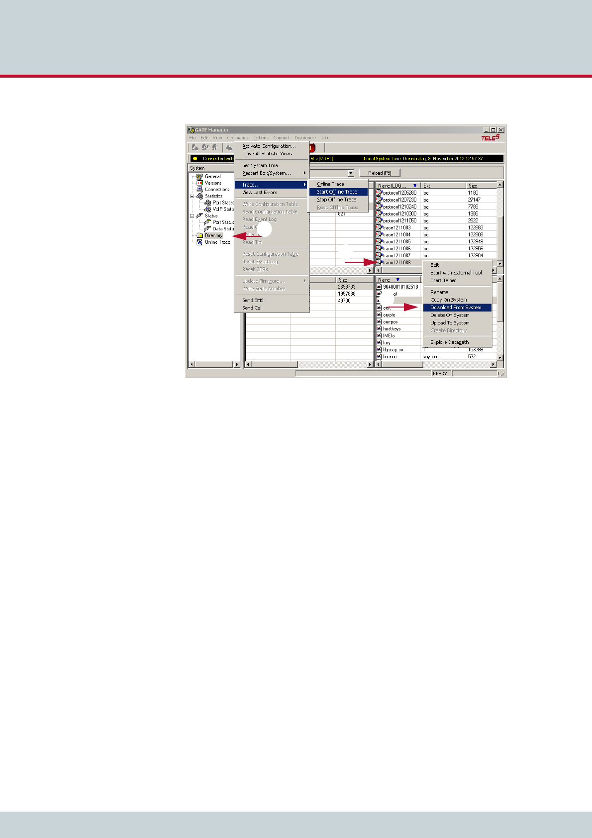
6 Maintenance
Page 63
CELLX box 17.1/002
11. Send the trace to customer service.
1
2
3

TELES COMMUNICATIONS CORP.
2400 Skyfarm Drive,
Hillsborough, CA 94010
United States
Phone: +1 646-225 65 98
E-Mail: cellx@teles.com
Internet: http://www.teles.com/cellx/index.html