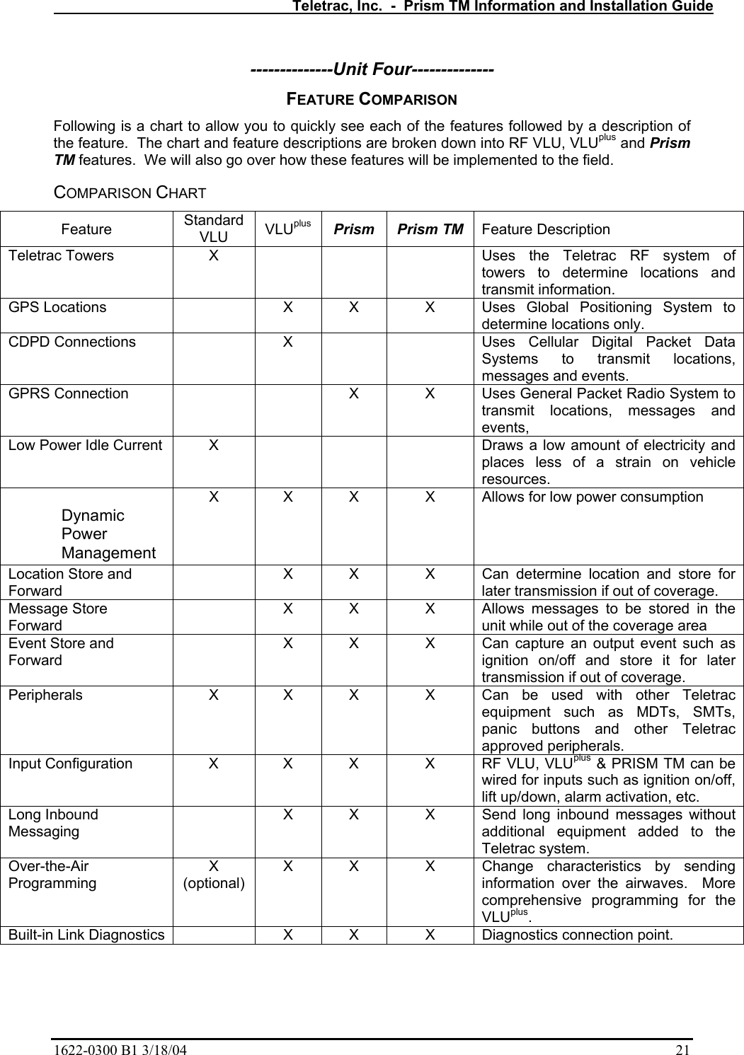
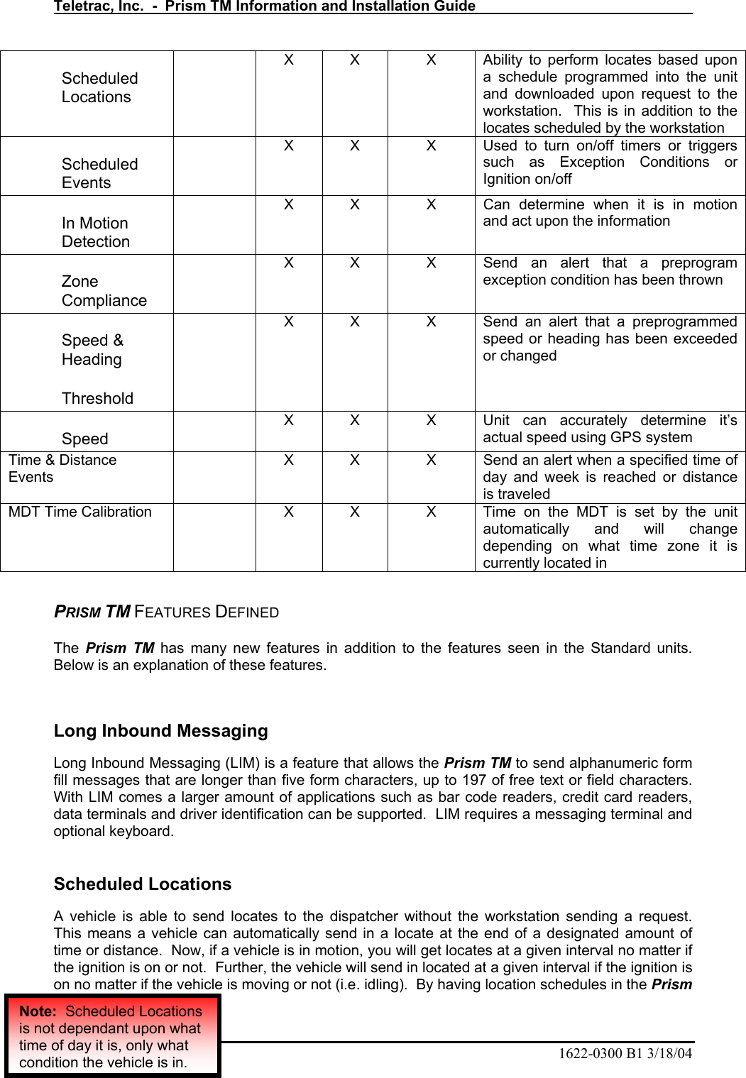
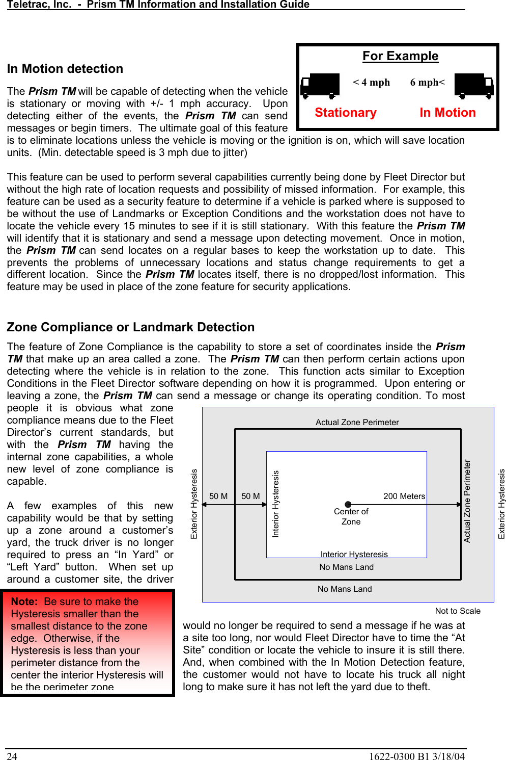
Teletrac ATLTRC GSM 900/1800/1900 Vehicle Tracking Device User Manual user Guide

Teletrac Inc GSM 900/1800/1900 Vehicle Tracking Device user Guide

user Guide

Prism TM  Teletrac Prism TM Information and Installation  Desired Learning Outcomes At the conclusion of this module you will:  Know the physical components that make up a Prism TM installation  Know the current feature set of the Prism TM  Know the components and processes used to acquire and transmit Prism TM information  Know the requirements and processes to install and test a Prism TM
Teletrac, Inc.  -  Prism TM Information and Installation Guide   2  1622-0300 B1 3/18/04
  Teletrac, Inc.  -  Prism TM Information and Installation Guide 1622-0300 B1 3/18/04    3 KEY PERFORMANCE INDICATORS With no direct supervision and with written guidelines, the Prism TM installer will be able to:   Describe the peripheral equipment used in a Prism TM installation  Identify the internal components that make up a Prism TM  Describe the method of how a Prism TM determines its location  Identify what information the Prism TM can communicate when different systems are hindered  List current features of the Prism TM   List the steps to replace a VLUplus with a Prism TM  List the steps to initially install a Prism TM
Teletrac, Inc.  -  Prism TM Information and Installation Guide   4  1622-0300 B1 3/18/04
  Teletrac, Inc.  -  Prism TM Information and Installation Guide 1622-0300 B1 3/18/04    5 Table of Contents  Introduction .................................................................................................................................................. 7 Physical characteristics ................................................................................................................................ 7 PRISM TM ................................................................................................................................................... 7 ANTENNAS .................................................................................................................................................. 8 PERIPHERALS .............................................................................................................................................. 8 The GPS and GPRS Systems....................................................................................................................... 9 GLOBAL POSITIONING SYSTEMS (GPS)....................................................................................................... 9 GPRS........................................................................................................................................................ 14 THE OVERALL TELETRAC PICTURE ........................................................................................................... 15 SUBSCRIBER IDENTITY MODULE (SIM) CARD .......................................................................................... 17 Prism TM Functionality............................................................................................................................. 19 DEFAULT SETTINGS................................................................................................................................... 19 Feature Comparison................................................................................................................................... 21 COMPARISON CHART ................................................................................................................................21 PRISM TM FEATURES DEFINED ................................................................................................................ 22 Long Inbound Messaging ..................................................................................................................... 22 Scheduled Locations............................................................................................................................. 22 In Motion detection............................................................................................................................... 24 Speed Threshold ................................................................................................................................... 25 Dynamic Power Management .............................................................................................................. 25 Message Store and Forward (Message History) .................................................................................. 26 PRISM TM  Installation Instructions .......................................................................................................28 PRE-INSTALLATION CONSIDERATIONS ......................................................................................... 28 ITEMS REQUIRED FOR PRISM TM INSTALLATION.................................................................................... 29 WIRING SCHEMATIC.................................................................................................................................. 29 ANTENNA PLACEMENT.............................................................................................................................. 30 PRISM TM INSTALLATION PROCEDURES ................................................................................................ 32 SWAPPING OUT A PRISM TM...................................................................................................................... 34 Prism TM Administration & Provisioning............................................................................................... 36 Appendix A – An Introduction to Global Positioning Satellite Systems................................................ 40 Appendix B – Teletrac Prism TM Antennas............................................................................................ 50 Appendix C – Installation Equipment ...................................................................................................... 52 Appendix D – How Messages Are Used In Scripts .................................................................................. 54 Appendix E – Pinouts for Standard Teletrac Harness............................................................................ 60 Appendix F – FCC Statement.................................................................................................................... 62 Appendix G - Safety Information.............................................................................................................. 63
Teletrac, Inc.  -  Prism TM Information and Installation Guide   6  1622-0300 B1 3/18/04
  Teletrac, Inc.  -  Prism TM Information and Installation Guide 1622-0300 B1 3/18/04    7 INTRODUCTION  Welcome to Teletrac’s Prism TM Information and Installation Guide.  The goal of this guide is to give you an understanding of how the Prism TM functions and how the different systems it uses function, as well as, how to install the Prism TM itself.  As you make your way through this guide, you will start to become familiar with many aspects of the Prism TM, however, nothing will replace the hands-on experience of installing a unit and seeing how it functions in person.  It is hoped that you will use this guide as a reference to give you guidance whenever a problem is encountered.   This guide starts with a discussion of the physical characteristics of the Prism TM and the equipment it requires to function.  Next is a brief introduction to the systems the Prism TM relys upon to do it’s job.  After that will be a feature list to compare the Prism TM to an RF & CDPD VLU along with descriptions of the features.  Lastly is a section on how to install and test the Prism TM.  Now, let’s get going…   --------------Unit One-------------- PHYSICAL CHARACTERISTICS  PRISM TM  The  Prism TM is a custom built transceiver made for Teletrac.  The device is a black anodized aluminum box roughly the same size as a CD carrying case.  Internally it consists of a GPRS modem, a GPS receiver, a controller board and a SIM card. The GPRS modem and GPS receiver are basically off-the-shelf devices. It’s the SIM card that makes this product unique.   The SIM (subscriber identity module) card is a small electronic board that contains the “personality” of the unit.  The SIM is a programmable card that can easily be moved from one unit to the next so that in the event of hardware failure the card can be remove and placed in a new unit without any reprogramming.  SIM cards and the GPRS system run on the GSM network which is considered to be one of the most secure communication systems since both data and voice are encrypted to prevent eavesdropping.  See Section Two for more information about how GSM, GPRS and SIM cards work.       In theory, the Prism TM should work about the same as a VLUplus.  It has been purposefully designed to have a similar wiring scheme and to use the same installed peripherals. See Unit Five for installation information.
Teletrac, Inc.  -  Prism TM Information and Installation Guide   8  1622-0300 B1 3/18/04 ANTENNAS  The Prism TM uses a hidden combo antenna or roof mount combo antenna.  In the future there will be more antenna options once the physical connector has changed.             Combo Hidden Antenna  Roof Mount combo Antenna   PERIPHERALS    MDT  The Prism TM is designed to use the same peripherals or accessories that the RF and CDPD VLU uses.  In addition to the same peripherals, the Prism TM currently has two inputs and two outputs.  Input 0 is configured to work with ignition on/off and inputs 1 & 2 allow for the connection of PTOs.
  Teletrac, Inc.  -  Prism TM Information and Installation Guide 1622-0300 B1 3/18/04    9 --------------Unit Two-------------- THE GPS AND GPRS SYSTEMS There are two systems that the Prism TM uses outside of the Teletrac system.  One is the Global Positioning System, more commonly called GPS and the other is the General Packet Radio System otherwise known as GPRS.  The following pages will give you a basic introduction to where these systems came from as well as how they work.  At the end of this section will be a summary of how Teletrac uses these two systems together to get the location of a vehicle.      GLOBAL POSITIONING SYSTEMS (GPS)  The following information was taken from information posted to the Teletrac Intranet.  Included here is the abridged version of GPS.  The full text appears in Appendix A at the end of this Information Guide.  AN INTRODUCTION TO GLOBAL POSITIONING SATELLITE SYSTEMS  Global Positioning Systems  GPS uses "man-made stars" or satellites as reference points to calculate positions on Earth accurate to within meters.  In fact, with advanced forms of GPS you can make measurements to better than a centimeter. In a sense, it's like giving every square meter on the planet a unique address.   Since GPS receivers have been miniaturized to just a few integrated circuits and have become very economical, the technology has become increasingly accessible.   Here's how GPS works in five logical steps:   Here is a summary of each of the steps involved with GPS in order to determine a location.  This is the first part of Teletrac finding the locations of vehicles using a Prism TM.  Once a location is determined then it is sent via another system.  We'll explain each of the following points in the next five sections.   1.  The basis of GPS is "triangulation" from satellites.  2.  To "triangulate," a GPS receiver measures distance using the travel time of radio signals.  3.  To measure travel time GPS needs very accurate timing, which it achieves with some tricks.
Teletrac, Inc.  -  Prism TM Information and Installation Guide   10  1622-0300 B1 3/18/04 4.  Along with distance, you need to know exactly where the satellites are in space. High orbits and careful monitoring are the secret.  5.  Finally you must correct for any delays the signal experiences as it travels through the atmosphere.   Step 1: Triangulating from Satellites Improbable as it may seem, the whole idea behind GPS is to use satellites in space as reference points for locations here on earth.  That's right, by very, very accurately measuring our distance from three satellites we can "triangulate" our position anywhere on earth.   Step 2: Measuring Distance from a Satellite But how can you measure the distance to something that's floating around in space? We do it by timing how long it takes for a signal sent from the satellite to arrive at our receiver.   THE BIG IDEA, MATHEMATICALLY  In a sense, the whole thing boils down to those "velocity times travel time" math problems we did in high school. Remember the old: "If a car goes 60 miles per hour for two hours, how far does it travel.?"  Velocity (60 mph) x Time (2 hours) = Distance (120 miles)  In the case of GPS we're measuring a radio signal so the velocity is going to be the speed of light, or roughly 186,000 miles per second.   Step 3: Getting Perfect Timing If measuring the travel time of a radio signal is the key to GPS, then our stop watches had better be darn good because if their timing is off by just a thousandth of a second, at the speed of light, that translates into almost 200 miles of error!  The secret to perfect timing is to make an extra satellite measurement.  That's right, if three perfect measurements can locate a point in 3-dimensional space, then four imperfect measurements can do the same thing.
  Teletrac, Inc.  -  Prism TM Information and Installation Guide 1622-0300 B1 3/18/04    11  EXTRA MEASUREMENT CURES TIMING OFFSET  If everything were perfect (i.e. if our receiver's clocks were perfect) then all of our satellite ranges would intersect at a single point (which is our position). But with imperfect clocks, a fourth measurement, done as a cross-check, will NOT intersect with the first three.  So the receiver's computer says "Uh-oh! There is a discrepancy in my measurements. I must not be perfectly synced with universal time."  Since any offset from universal time will affect all of our measurements, the receiver looks for a single correction factor that it can subtract from all its timing measurements that would cause them all to intersect at a single point.  That correction brings the receiver's clock back into sync with universal time, and bingo! - you've got atomic accuracy time right in the palm of your hand. Once it has that correction it applies to all the rest of its measurements, and now we've got precise positioning.   Step 4: Knowing Where a Satellite is in Space  On the ground all GPS receivers have an almanac programmed into their computers that tells them where in the sky each satellite is, moment by moment.   CONSTANT MONITORING ADDS PRECISION  The basic orbits are quite exact but just to make things perfect, the GPS satellites are constantly monitored by the Department of Defense.   They use very precise radar to check each satellite's exact altitude, position and speed.
Teletrac, Inc.  -  Prism TM Information and Installation Guide   12  1622-0300 B1 3/18/04  GETTING THE MESSAGE OUT  Once the DoD has measured a satellite's exact position, they relay that information back up to the satellite itself. The satellite then includes this new corrected position information in the timing signals it's broadcasting.     Step 5: Correcting Errors   ROUGH TRIP THROUGH THE ATMOSPHERE  First, one of the basic assumptions we've been using throughout this tutorial is not exactly true. We've been saying that you calculate distance to a satellite by multiplying a signal's travel time by the speed of light. But the speed of light is only constant in a vacuum.  As a GPS signal passes through the charged particles of the ionosphere and then through the water vapor in the troposphere it gets slowed down a bit, and this creates the same kind of error as bad clocks.
  Teletrac, Inc.  -  Prism TM Information and Installation Guide 1622-0300 B1 3/18/04    13  ROUGH TRIP ON THE GROUND  Trouble for the GPS signal doesn't end when it gets down to the ground. The signal may bounce off various local obstructions before it gets to our receiver.   This is called multipath error and is similar to the ghosting you might see on a TV. Good receivers use sophisticated signal rejection techniques to minimize this problem.   PROBLEMS AT THE SATELLITE  The atomic clocks they use are very, very precise but they're not perfect. Minute discrepancies can occur, and these translate into travel time measurement errors.   SOME ANGLES ARE BETTER THAN OTHERS  There are usually more satellites available than a receiver needs to fix a position, so the receiver picks a few and ignores the rest.  If it picks satellites that are close together in the sky the intersecting circles that define a position will cross at very shallow angles. That increases the gray area, or error margin, around a position. Commonly refered to as HDOP.  If it picks satellites that are widely separated, the circles intersect at almost right angles and that minimizes the error region.
Teletrac, Inc.  -  Prism TM Information and Installation Guide   14  1622-0300 B1 3/18/04 Intentional Errors!  As hard as it may be to believe, the same government that spent $12 billion to develop the most accurate navigation system in the world can cause errors by intentionally degrading its accuracy. The policy is called "Selective Availability" or "SA" and the idea behind it is to make sure that no hostile force or terrorist group can use GPS to make accurate weapons.  Basically the DoD introduces some "noise" into the satellite's clock data which, in turn, adds noise (or inaccuracy) into position calculations. The DoD may also be sending slightly erroneous orbital data to the satellites which they transmit back to receivers on the ground as part of a status message.  Together these factors make SA the biggest single source of inaccuracy in the system. Military receivers use a decryption key to remove the SA errors and so they're much more accurate.  Note:  As of Spring 2000, the DoD eliminated the intentional error in the calculation, however, this may come back at any time.  The Bottom Line  Fortunately, all of these inaccuracies still don't add up to much of an error, and a form of GPS called "Differential GPS" can significantly reduce these problems.    GPRS  The second system used by the Prism TM is the General Packet Radio System, more commonly called GPRS.  This system is meant to be an invisible link from a mobile unit, such as a wireless modem, to land line systems.  The next few pages will give you an introduction to GPRS and how it works to transmit information. The following information was taken from information posted to  http://www.rysavy.com/Articles/GPRS2/gprs2.html and http://www.geocities.com/mobile4g/gprs.html.     AN INTRODUCTION TO GENERAL PACKET RADIO SERVICE  What is GPRS?  GPRS offers packet-switched connections to data networks via mobile technology. It is designed to allow faster and easier Internet access with continuous connectivity, and enables applications including multimedia messaging, wireless corporate intranet, remote control and maintenance of appliances. It is also considered part of the migration to third generation (3G) mobile networks. The advantages of GPRS technology allows users to stay connected to the Internet by using packet switching technology, providing faster downloads as no time is spent attempting to access a dial-up connection.   How does GPRS work?  GPRS transports packets between mobile devices and packet networks. Packets can be IP or X.25, though with the Internet's popularity, operators and device vendors will probably emphasize IP. Mobile devices will have an IP address, either static or dynamic, and, once on the network, IP
  Teletrac, Inc.  -  Prism TM Information and Installation Guide 1622-0300 B1 3/18/04    15 packets can originate from mobile devices and travel to external networks, such as the Internet or privately connected intranets. IP packets from external networks will reach mobile devices, even when moving. GPRS doesn't care what protocols operate above IP. This indifference enables all standard Internet protocols to operate, including TCP, UDP, HTTP, Secure Sockets Layer (SSL), and IPSec.  GPRS uses two essential new infrastructure elements, the Serving GPRS Support Node (SGSN) and Gateway GPRS Support Node (GGSN). The SGSN, which connects to base-station controllers, tracks the mobile station's location and sends data packets to and from the mobile station. It forwards packets using a tunneling protocol to the GGSN, which acts as a gateway to external networks, such as the Internet or private intranets. An operator will have multiple SGSNs for different service areas, but needs only one GGSN for each external network it interconnects with. The GGSN assigns IP addresses to mobile stations, and IP packets from external networks route to the GGSN, which tunnels them to the appropriate SGSN for delivery to the mobile station.  Architecture and protocols are fine, but how do users actually connect to the network and send data, and how does the network keep track of users as they move around? When users turn on the GPRS device (GPRS PC Card modem) in a GPRS coverage area, the device first registers with the network and then requests a Packet Data Protocol (PDP) context. The PDP context activates an IP address for the device, generally a dynamic address assigned by the GGSN. At this stage the device can send and receive data.  To actually send a packet of data, the device makes requests using a packet random-access channel. Channels are logical data paths consisting of predefined time slots in select GPRS radio channels, and are the primary mechanism in the MAC layer. The network responds by assigning a data-traffic channel for a temporary period sufficient to send the data packet. GPRS networks use 200KHz radio channels, with each channel divided into eight time slots. Each time slot can support 13Kbits/sec of throughput in today's networks (though options exist to increase data rates to over 20Kbits/sec), and so actual user throughput will depend on the number of time slots a user's device can handle and the particular service options from the carrier.  To support mobility, the GPRS device informs the SGSN when it's within a new base station's coverage range. If the user travels out of one SGSN's coverage to another, then the old SGSN and the new SGSN must collaborate and inform the GGSN of the user's new location. Users will also be able to roam into networks operated by other GPRS carriers.    THE OVERALL TELETRAC PICTURE  Now that you have an understanding of GPS and GPRS, let’s talk about how Teletrac uses these systems in order to provide location and messaging services to our customers.  In Unit One we talked about the components that make up the Prism TM, now let’s talk about how those components work together. As shown in the diagram, a computer running eClient connects to the Teletrac NCC via the Internet.  The NCC is where all the customer databases are stored and where customer location requests are processed.  From eClient eClientGPRS SiteCDPD SiteRadio TowerGPS SatelliteTeletrac NCCInternet InternetThe three types of location systems Teletrac usesVLUplus or VLU-GRF VLU
Teletrac, Inc.  -  Prism TM Information and Installation Guide   16  1622-0300 B1 3/18/04 there, the NCC contacts the customer’s vehicles via the Internet.  The vehicles that use GPS to determine their location send that information directly to the NCC and it is in turn sent back to the eClient workstation.   The GPS receiver built into the Prism TM works to determine the location of itself.  As long as the receiver is able to see enough satellites it can tell the Prism TM where it is.  If a vehicle drives into an underground garage, inside a warehouse or even under an overpass, the receiver may not be able to see enough, if any, satellites to determine it’s location.  Since the signals coming from the satellites to the receiver are very low they can easily be blocked, even dense cloud cover can reduce the actual signal.   The GPS receiver will determine its location every few seconds and store the information.  When the Prism TM Controller is contacted through the GPRS modem, the Controller contacts the GPS receiver and a request is made for its location at a certain time.  Once the Controller receives the location information from the GPS receiver, it relays the locate to the Teletrac NCC via the GPRS modem.  Even if the GPRS modem cannot be contacted by the NCC, the GPS receiver is still collecting the information on where it is located.  When the GPRS modem is able to communicate with the NCC, the Prism TM will download the location information that the GPS receiver has been providing. Now, lets say your driver is taking a lunch break under the awning of a drive-up restaurant.  In this location the GPS receiver probably cannot see enough satellites to determine it’s location.  In this event, when the controller requests a locate from the GPS receiver, the last known location will be used.  Since the receiver takes it’s own readings every few seconds the last known location is probably just outside the restaurant awning.  When it’s time to send in a locate to the NCC, the Prism TM can still “pick up” the GPRS modem and contact the NCC.  But, the only location that will be returned is the last known location reported to the Prism TM Controller, which was probably just outside the awning.  This location will be reported as a poor quality locate and display as the last known location.   Even though the GPS receiver is blocked, a dispatcher can still send messages to a driver.  Since the messages travel over the GPRS system they will be sent to the Prism TM and simply a poor locate (last known location) will be returned to the dispatcher. Lastly, the Prism TM can be set up to store events such as ignition on/off, messages and location information when the GPRS modem is out of it’s coverage area.  The events, messages and locations can be stored in a memory buffer and later transmitted once the modem is able to communicate.  See the following chart to help explain what happens when each system is able to operate or is blocked.       GPRS Communication to NCCSatelliteGPRS ModemControl BoardGPS ReceiverLocation Unit
  Teletrac, Inc.  -  Prism TM Information and Installation Guide 1622-0300 B1 3/18/04    17   SUBSCRIBER IDENTITY MODULE (SIM) CARD Each Subscriber Identity Module is programmed with specific identification features for a unique user, allowing the device that contains a module to be used for such things as online banking and purchasing that require a secure means of identification. They can be swapped between other GSM devices, so the Subscriber Identity Module owner isn't confined to a single device.  Teletrac will use the SIM Cards as a quick way to move specific programming information from one location unit to another.  The SIM Card will contain information such as location schedules, landmarks, service reminders etc.  When the hardware of a locator unit goes bad an installer will replace the hardware and take the SIM Card from the broken device and place it in the new device.  This will move all the programmed information and alleviate the need to reprogram units.    PRISM PRISM PRISM PRISM Can Locate, Message & Send Events Can Message & Send Events, Last Known Good Location is Sent Storing of Locations, Events & Messages in a buffer to transmit later Store Events, Messages & Locates, Last Locate is sent to W/S
Teletrac, Inc.  -  Prism TM Information and Installation Guide   18  1622-0300 B1 3/18/04
  Teletrac, Inc.  -  Prism TM Information and Installation Guide 1622-0300 B1 3/18/04    19 --------------Unit Three-------------- PRISM TM FUNCTIONALITY The Prism TM is designed to behave the same way as the VLUplus unit and have the same features available.  However, the Prism TM is not as programmable as the VLUplus.  Instead of having a script, the Prism TM has a hard coded set of instructions that can have some small configuration changes.  Below is a list of how the unit will act by default; changes to the configuration will be a future implementation.  See Unit Four for a description of the features available, as well as, a feature comparison between all the Teletrac units.   DEFAULT SETTINGS  Default New Power Management:  ----  ---- Wait time until unit goes to sleep  4 hours    How long should it sleep  4 hours    When it wakes, how long should it wait to acquire GPS and CDPD signals 4 minutes   Wait time between sending “going to sleep” message and actually going to sleep 6 minute   Will the units use Ignition On/Off messaging  ----  Y      N Will the unit self locate when in coverage  ----  Y      N How will the unit be located? Workstation or Locate itself  ----  Wkstn   Itself Location schedule when the vehicle locates itself  15 min / -- miles   Maximum speed limit  75 mph   Reminder message for exceeding the speed limit (i.e. when a vehicle exceeds the speed limit you will get a message, then, every 5 min that the driver is speeding you will get another message.) 5 minutes   Would you like to use Service Mileage?  ----  Y       N             Number of miles between services 3000 miles   Number of miles to receive service reminder message 50 miles   Will the units use Tow Away messaging  ----  Y       N           If yes, how soon after the vehicle moves should a            message be sent 60 seconds    The Prism TM can also be programmed with landmarks, either rectangles or circles.   When a vehicle goes into or out of the zone a message is sent in, no matter what time of day it is.  Programming the unit with the Lat/Long of the center then either the radius of the circle or the distance North/South and East/West in meters creates a landmark.
Teletrac, Inc.  -  Prism TM Information and Installation Guide   20  1622-0300 B1 3/18/04
  Teletrac, Inc.  -  Prism TM Information and Installation Guide 1622-0300 B1 3/18/04    21 --------------Unit Four-------------- FEATURE COMPARISON Following is a chart to allow you to quickly see each of the features followed by a description of the feature.  The chart and feature descriptions are broken down into RF VLU, VLUplus and Prism TM features.  We will also go over how these features will be implemented to the field.  COMPARISON CHART Feature  Standard VLU  VLUplus Prism Prism TM Feature Description Teletrac Towers  X        Uses the Teletrac RF system of towers to determine locations and transmit information. GPS Locations    X  X  X  Uses Global Positioning System to determine locations only. CDPD Connections    X      Uses Cellular Digital Packet Data Systems to transmit locations, messages and events. GPRS Connection      X  X  Uses General Packet Radio System to transmit locations, messages and events, Low Power Idle Current  X        Draws a low amount of electricity and places less of a strain on vehicle resources. Dynamic Power Management X  X  X  X  Allows for low power consumption Location Store and Forward   X  X  X  Can determine location and store for later transmission if out of coverage. Message Store Forward  X  X  X  Allows messages to be stored in the unit while out of the coverage area Event Store and Forward   X  X  X  Can capture an output event such as ignition on/off and store it for later transmission if out of coverage. Peripherals  X  X  X  X  Can be used with other Teletrac equipment such as MDTs, SMTs, panic buttons and other Teletrac approved peripherals. Input Configuration  X  X  X  X  RF VLU, VLUplus & PRISM TM can be wired for inputs such as ignition on/off, lift up/down, alarm activation, etc.   Long Inbound Messaging   X  X  X  Send long inbound messages without additional equipment added to the Teletrac system. Over-the-Air Programming X (optional) X  X  X  Change characteristics by sending information over the airwaves.  More comprehensive programming for the VLUplus. Built-in Link Diagnostics   X  X  X  Diagnostics connection point.
Teletrac, Inc.  -  Prism TM Information and Installation Guide   22  1622-0300 B1 3/18/04 Scheduled Locations   X  X  X  Ability to perform locates based upon a schedule programmed into the unit and downloaded upon request to the workstation.  This is in addition to the locates scheduled by the workstation Scheduled Events   X  X  X  Used to turn on/off timers or triggers such as Exception Conditions or Ignition on/off In Motion Detection   X  X  X  Can determine when it is in motion and act upon the information Zone Compliance   X  X  X  Send an alert that a preprogram exception condition has been thrown Speed & Heading  Threshold   X  X  X  Send an alert that a preprogrammed speed or heading has been exceeded or changed Speed   X  X  X  Unit can accurately determine it’s actual speed using GPS system Time & Distance Events  X  X  X  Send an alert when a specified time of day and week is reached or distance is traveled MDT Time Calibration   X  X  X  Time on the MDT is set by the unit automatically and will change depending on what time zone it is currently located in  PRISM TM FEATURES DEFINED The  Prism TM has many new features in addition to the features seen in the Standard units.  Below is an explanation of these features.  Long Inbound Messaging Long Inbound Messaging (LIM) is a feature that allows the Prism TM to send alphanumeric form fill messages that are longer than five form characters, up to 197 of free text or field characters.  With LIM comes a larger amount of applications such as bar code readers, credit card readers, data terminals and driver identification can be supported.  LIM requires a messaging terminal and optional keyboard.  Scheduled Locations A vehicle is able to send locates to the dispatcher without the workstation sending a request.  This means a vehicle can automatically send in a locate at the end of a designated amount of time or distance.  Now, if a vehicle is in motion, you will get locates at a given interval no matter if the ignition is on or not.  Further, the vehicle will send in located at a given interval if the ignition is on no matter if the vehicle is moving or not (i.e. idling).  By having location schedules in the Prism Note:  Scheduled Locations is not dependant upon what time of day it is, only what condition the vehicle is in.
  Teletrac, Inc.  -  Prism TM Information and Installation Guide 1622-0300 B1 3/18/04    23 TM, the unit changes it’s own schedule through the condition of the vehicle and doesn’t require a message with a status change be sent to the workstation in order to change it’s location schedule.  Also, since a location schedule can also be stopped due to the vehicle’s condition (Ignition off and Not moving), a lot of unnecessary locates and locations requests are eliminated thereby, reducing airtime usage.
Teletrac, Inc.  -  Prism TM Information and Installation Guide   24  1622-0300 B1 3/18/04  In Motion detection   The Prism TM will be capable of detecting when the vehicle is stationary or moving with +/- 1 mph accuracy.  Upon detecting either of the events, the Prism TM can send messages or begin timers.  The ultimate goal of this feature is to eliminate locations unless the vehicle is moving or the ignition is on, which will save location units.  (Min. detectable speed is 3 mph due to jitter)  This feature can be used to perform several capabilities currently being done by Fleet Director but without the high rate of location requests and possibility of missed information.  For example, this feature can be used as a security feature to determine if a vehicle is parked where is supposed to be without the use of Landmarks or Exception Conditions and the workstation does not have to locate the vehicle every 15 minutes to see if it is still stationary.  With this feature the Prism TM will identify that it is stationary and send a message upon detecting movement.  Once in motion, the  Prism TM can send locates on a regular bases to keep the workstation up to date.  This prevents the problems of unnecessary locations and status change requirements to get a different location.  Since the Prism TM locates itself, there is no dropped/lost information.  This feature may be used in place of the zone feature for security applications.   Zone Compliance or Landmark Detection The feature of Zone Compliance is the capability to store a set of coordinates inside the Prism TM that make up an area called a zone.  The Prism TM can then perform certain actions upon detecting where the vehicle is in relation to the zone.  This function acts similar to Exception Conditions in the Fleet Director software depending on how it is programmed.  Upon entering or leaving a zone, the Prism TM can send a message or change its operating condition. To most people it is obvious what zone compliance means due to the Fleet Director’s current standards, but with the Prism TM having the internal zone capabilities, a whole new level of zone compliance is capable.   A few examples of this new capability would be that by setting up a zone around a customer’s yard, the truck driver is no longer required to press an “In Yard” or “Left Yard” button.  When set up around a customer site, the driver would no longer be required to send a message if he was at a site too long, nor would Fleet Director have to time the “At Site” condition or locate the vehicle to insure it is still there.  And, when combined with the In Motion Detection feature, the customer would not have to locate his truck all night long to make sure it has not left the yard due to theft.   texttext200 MetersNo Mans LandNo Mans LandExterior HysteresisExterior HysteresisInterior HysteresisInterior Hysteresis50 MCenter ofZoneActual Zone PerimeterActual Zone PerimeterNot to Scale50 MNote:  Be sure to make the Hysteresis smaller than the smallest distance to the zone edge.  Otherwise, if the Hysteresis is less than your perimeter distance from the center the interior Hysteresis will be the perimeter zone< 4 mph Stationary 6 mph< In Motion For Example
  Teletrac, Inc.  -  Prism TM Information and Installation Guide 1622-0300 B1 3/18/04    25  In addition, since the GPS Receiver is locating itself continually, the Prism TM would send a message with the exact time of the event happening.  This would eliminate the 15-minute error factor in Fleet Director.  There are a maximum of three (3) zones that can be configured into each unit.  A zone can either be a circle with a center and radius or a square with a center and distance to the edge.  In order to determine a zone, you will need to find the Latitude and Longitude for the center of the zone.  Next, determine the distance, in meters, from the center of the zone to its edge.    Next, you will need to determine the Hysteresis.  This is a gray area outside and inside the edges of the zone that will account for jitter in the locations.  You will be able to select the size of the Hysteresis from 0 meters to 250 meters.  Within the Hysteresis, you will not be considered inside or outside the zone.  The vehicle will effectively be in “No Mans Land”.  The Hysteresis can also be turned off so that the actual edges of the zone are used for the exception.   Speed Threshold  A natural spin-off from time and distance is speed.  The Prism TM can detect its own speed more accurately then Fleet Director (+/- 1 mph accuracy).  Because of this, the Prism TM can detect speed violations thus alerting dispatch of possible violations or exception condition.   Thresholds can be set in the Prism TM to trigger warning messages when the vehicle goes above a specific speed.  Even more, a timer can be set to alert dispatch only if the threshold is detected for a required length of time.  In order for the messages to be sent, the speed must pass through the set speed.  Dynamic Power Management By default, the Prism TM is programmed with a robust interactive power management routine.  This routine forces the Prism TM to periodically shut down its internal high current components (the GPRS modem and the GPS receiver) while the vehicle ignition is OFF.  This feature will decrease the Prism TM current consumption significantly.  While these components are shut down, the workstation is incapable of setting up a communications link with the Prism TM for the requesting of location or the sending of messages. While the Prism TM is asleep the ability to send messages from the MDT and do vehicle status changes (in motions, input change, etc.) will not be prevented but may suffer a slight delay caused by the Prism TM waking up.  To the customer (and the system) it appears as though the Prism TM is out of the coverage area while the Prism TM is asleep.  To reduce the possible confusion as to if the unit is asleep or out of coverage, when the unit goes to sleep it will send a message prior to shutting down to indicate the shut down and to inform how long the unit will be asleep.  Otherwise, if no message is captured then the unit is out of the coverage area.  When the unit does go to sleep, it will check it’s operating conditions to see if it is allowed to go to sleep then, it will start a timer, if the conditions remain the same at the end of the timer then the unit will go to sleep.  The unit will send a message to the workstations saying that in X minutes it will be going to sleep hys·ter·e·sis (h s t -r ss)  n., pl. hys·ter·e·ses (-s z.)  The lagging of an effect behind its cause, as when the change in magnetism of a body lags behind changes in the magnetic field Note:  Unit must have the following conditions in order to go to sleep: Ignition Off Not moving Note:  The actual speed must pass through the set speed in order to trigger the message.
Teletrac, Inc.  -  Prism TM Information and Installation Guide   26  1622-0300 B1 3/18/04 for Y hours (this message must be set up in Fleet Director as a message for now).  Once the Prism TM has gone to sleep it is unreachable until the operating conditions change or it is time to wake up.  If the unit wakes up and determines that the operating conditions have not changed it will send out the same message as above.    In order to keep a unit awake, the operating conditions must change.  For instance, since the Prism TM is connected to sense ignition on/off, when the ignition is turned on the unit will wake up.  Another way to keep the unit awake is to keep it busy.  By moving the unit into a status that locates it more frequently than the time required for it to go to sleep, it will remain awake since the timer is reset after each activity with the unit.  When a unit is out of the coverage area or asleep, it will send messages to the buffer.  Once the messages are in the buffer they are stored until they are downloaded.  The unit will still go to sleep with messages in the buffer.  Events or reports that occur while the unit is asleep will still be stored in the buffer.  When programming the Prism TM, you will have the option to fill in the amount of time the unit will wait once it has determined that it can go to sleep, how long it will remain asleep and how long it will stay awake when it does wake up.   Message Store and Forward (Message History) The unit has ability to store locations, event history and messages.  Any of these pieces of data can be stored while the Prism TM migrates outside the GPRS coverage area.  The unit will first attempt to send the message or event, if it fails, the message will be sent to a memory buffer for later delivery.  When a report is run, the coverage area will appear greater. With the addition of storing message, this feature will allow the driver to continue to send status messages while outside the GPRS coverage area to time stamp his activities so a compliance report can be generated when he returns to the GPRS coverage area.  Also, the messages will be stored even if the unit goes to sleep.
  Teletrac, Inc.  -  Prism TM Information and Installation Guide 1622-0300 B1 3/18/04    27
Teletrac, Inc.  -  Prism TM Information and Installation Guide   28  1622-0300 B1 3/18/04  --------------Unit Five-------------- PRISM TM  INSTALLATION INSTRUCTIONS  This unit covers the installation of the PRISM TM.  We will take a look at the equipment and walk through a typical installation.  As a note, this section does not cover the programming of the PRISM TM.   NOTE: This section discusses a typical installation in a step-by-step fashion.  Please e-mail the Field Service group for questions concerning special installations.  PRE-INSTALLATION CONSIDERATIONS a)  Perform a Pre-installation Vehicle Checkout.  Ensure that major electrical/mechanical components are in working order in the event anything happens to the vehicle at a later date.  Check the headlamps, air conditioner, dome lights, turn signals, radio, windshield wipers and, if at all possible, start the vehicle engine. b)  Prior to beginning the PRISM TM installation, record the unit’s IP address and vehicle ID on the installation form.  The stickers, created at the time of provisioning, need to be affixed to the installation forms.  A set of these forms is to be left with the customer and a set placed in their file.  This reduces the need to uninstall the unit then reinstall it in order to find the unit’s number.  The units will have their MIN activated upon provisioning in the metro.  Upon MIN activation Teletrac starts paying for it’s use and therefore, units should be installed as quickly as possible and not kept in stock. c)  Next, remove the courtesy light fuse in order to avoid running the vehicles battery down during installation. d)  Before beginning any work you will need to find suitable locations for the following equipment.  As a courtesy, all equipment will be installed in a manner that will conceal its location, usually behind the dashboard.  You will need a flat surface for mounting.  Also, keep in mind that coax for the antennas must be run behind panels and in pillars.  Review the equipment location with the customer and obtain their approval. PRISM TM Transceiver Combo antennas Cable runs MDT 12 VDC and ground spots e)  While you are determining the mounting location use the system layout as a reference to plan the wiring harness routing and connection points.  Typical locations are under or behind the vehicle dashboard.   Avoid places with extreme vibration, heat or moisture.   f)  Once the hardware is mounted and when you are making the wiring connections, hold the PRISM TM in place and route the unit’s wiring harness to the connection point at the target wire.  Cut the wires to the correct length and make the connections.  Once the first installation is complete you can prepare the rest of the equipment (harnesses) in advance of the actual installation. NOTE:  Due to the importance of the connections, it is mandatory that all connections be either Soldered or Crimped with the proper crimping tool.  Wrap and tape, Scotch-Loc., or T-Tap connections MAY NOT BE USED when installing this system.
  Teletrac, Inc.  -  Prism TM Information and Installation Guide 1622-0300 B1 3/18/04    29 ITEMS REQUIRED FOR PRISM TM INSTALLATION In order to complete the installation of a Prism TM you will need to have the following equipment on hand:  • PRISM TM - Previously tested and activated with GPRS service and IP address • GPS Antenna - Through-hole or magnetic mount or a combo antenna • GPRS Antenna - 3dB gain whip, with either NMO or magnetic mount or a combo antenna • Wiring harness - Standard PRISM TM harness with 8-pin connector or VLU to PRISM adapter • PRISM TM to VLU Adapter – One foot long wiring adapter to connect the Teletrac harness to the Prism. • Hook-up wire - 22 AWG, minimum • Installation Tools - Soldering iron, crimper, press hole punch, 7/8" punch, and misc. tool kit. • MDT – optional • Laptop – with HyperTerminal to do testing  WIRING SCHEMATIC There are two unique wiring schematics; one for replacing a VLUplus with a PRISM TM and one for a new installation of a Prism.  For a replacement installation you will need to use the VLU to PRISM TM adapter and for a new installation you will need to use the PRISM TM harness.  There are a couple of differences between the standard VLU and PRISM TM harnesses, in particular, the PRISM TM ground is a bare wire and the PRISM TM ignition is orange.  Prism TM to VLU/VLU+AdapterPrismGPS AntennaGPRS AntennaSMBSMAMDTConnectorGrn/Blue - Green LED NOT USEDRd/Wht - Red LED NOT USEDOrange - Aux 1 input +/-Black/White - Aux 2 input +/-Black/Red - Aux 2 output 100maYllw/Rd - Output 3 NOT USEDBlck/Yllw - Input 3 NOT USEDBlack - Chassis GroundWhite - True Ignition - Not AccessoryRed - Battery +Standard Teletrac Harness  Figure 1: Replacement Schematic with VLU to PRISM TM Adapter  See Appendix F for complete Teletrac harness pinouts
Teletrac, Inc.  -  Prism TM Information and Installation Guide   30  1622-0300 B1 3/18/04 PrismGPS AntennaGPRS AntennaSMBRed - Batt (+) 12 VDCGreen/Blue - Led 2Red/White -  Led 1Yellow - Relay 2Blue - Relay 1Black - Ground (-)Orange - High 1 INGray -  High 2 INWhite - IgnitionBlack - RS232 GroundYellow - RS232 RXWhite - RS232 TXBlack - Main GroundRed - Main 12 VDC (+)Orange/Black - Low 1 INGray/Black - Low 2 INSMA  Figure 2 PRISM TM Wiring Scheme   NOTE:  To insure that the GPS receiver and power management functions operate properly, it is essential that the Power input be connected to a constant (unswitched) +12 VDC supply and the Ignition input be connected to the vehicle ignition or another appropriate key operated line, such as ACCESSORY that goes low during engine cranking.   ANTENNA PLACEMENT Available Antennas  NAME VLUplus PRISM PRISM TM Black 3db Whip  X  X  X White Combo  X  X  X Hidden Combo – ARC (see note below) X X  X Glass Mount Combo  X  NO NO  GPS Antenna Now that there are two antennas and one is a GPS antenna, placement becomes critical. The received signal levels for the GPS antenna from the satellites are very low in power (approximately -136 dBm) so that any blockage of the antenna can affect the quality of the location computed by the receiver. The following figures show examples of good and poor vehicle GPS antenna mounting locations.   When installing the GPS antenna on a vehicle roof, make sure there are no obstructions close to the antenna that might block the view 360° to the horizon. Nothing should block the antenna 5° above the horizon - for example, air horns or marker lights. The best location is usually near the center of the roof, although it is also desirable to locate the cellular antenna as far from the GPS antenna as is practical.  It is best to keep the antenna at least 12” from any other antenna.  IF using the hidden combo antenna, it should be placed on the highest part of the dash or inside the headliner, see the note below.  Be sure to use the correct antenna for this application.
  Teletrac, Inc.  -  Prism TM Information and Installation Guide 1622-0300 B1 3/18/04    31 Also, kinks or tight knots in the antenna cable can cause problems that will not allow the PRISM TM to operate. When laying out the antenna cable, care should be taken so that the cable will not be subjected to crushing or strain.     Examples of good and poor GPS antenna placement  NOTE:  To insure that Hidden Combo – ARC antenna will function properly, mount the antenna’s base (large flat side) against a metal surface. NEVER shorten or lengthen the antenna co-ax cable.  NEVER locate the antenna near the transceiver unit, or other black box device.     NEVER mount the antenna vertically.  NEVER mount the antenna below the “beltline” of the vehicle.  NEVER mount the antenna in the trunk or engine compartment.  NEVER use silver (metallic) duct tape to secure the antenna  GPS performance will be less than optimum when using a hidden antenna.  When using this type of antenna, be aware of surrounding obstructions that could further reduce GPS operation.  GPRS Antenna The cellular antenna used by the PRISM TM for GPRS service is a standard black 3dB gain whip. It mounts with a standard NMO "Motorola" mount and requires ground plane to work properly. If possible, the GPRS antenna should be locate at least 12” from any other antenna.  Ensure that the cable does not get crushed during installation.  3 dB Gain Cellular Antenna for GPRS   No Blockage  above 5°
Teletrac, Inc.  -  Prism TM Information and Installation Guide   32  1622-0300 B1 3/18/04  PRISM TM INSTALLATION PROCEDURES Once you have all your tools in order and have planned the location of all the devices, you are ready to install the unit.  Following are the steps for two types of installations, replacement of an existing VLUplus OR Prism and installation of a new PRISM TM.    Replacing a VLUplus with a PRISM TM   You can use all the same wiring and only need to switch out the unit itself.  However, there will be an adapter between the unit and the VLUplus harness; see wiring schematic.    1.  Locate the existing VLUplus and remove the fuse or disconnect main power to the VLUplus at the power source. 2.  Disconnect the antennas from the VLUplus. 3.  Disconnect the 37-pin VLUplus wiring harness.  4. Remove VLUplus and note the IP address. 5.  Using a voltmeter, make sure that the ignition line (white harness wire pin 6) is correctly wired to the keyed side of the ignition switch at the ACCESSORY wire. This wire goes high upon turning the key but it goes low when at the CRANK position.  Also that the power input (red wire) is connected to a constant (unswitched) +12v DC supply. 6.   Verify that the existing harness has all required wires soldered or crimped for reliability.  7.  Attach the VLUplus wiring harness 37-pin connector to the adapter, tighten the screws, and then plug the adapter into the PRISM TM unit.   8. Mount the PRISM TM to the chassis of the vehicle utilizing the mounting tabs.  Secure the unit with four (4) self-tapping machine screws.   9.  A new antenna must be installed since the connectors from the Connect the SMA connector to the GPRS antenna port on the unit.  Connect the SMB GPS connector to the PRISM TM. 10.  Reattach the main vehicle power and/or replace the fuse.  PRISM TM New Installations  1.  Find suitable locations for the PRISM TM, and GPS/GPRS combo antenna.  Select a PRISM TM mounting location that is free of moisture or heat, typically behind the dashboard or under the seat. 2.  Install the GPS antenna and route the cable to the PRISM TM location.  Typically, the installation will require a hole drilled into the vehicle.  The exact size of the hole is dependant upon the antenna mount used.  Keep in mind that coax must be run behind panels.  Note that the GPS antenna should have no blockage 5° above the horizon.  (See Antenna Placement page 5.) 3.  Install the GPRS antenna and route the antenna cable to the PRISM TM location.  This will also typically require a hole drilled into the vehicle.  The exact size of the hole is dependant upon the antenna mount used.  Keep in mind that coax must be run behind panels. (See Antenna Placement page 5.) If a Combo antenna is being used only one hole will be required. 4.  Apply silicone around both antenna bases if holes are required.
  Teletrac, Inc.  -  Prism TM Information and Installation Guide 1622-0300 B1 3/18/04    33 5. Connect the PRISM TM wiring harness as recommended below.  For safety, remove fuse until installation is complete.  Never tap into existing power or ignition wires used from other aftermarket devices. Ground – Locate chassis ground within one (1) foot of the PRISM TM placement.  If chassis has sound absorbent materials, scrape materials and/or paint until you reach clean metallic surface.  Always use a star washer when attaching to chassis ground. Run Constant +12 Volt Wire – Attach one end of the fuse holder to determined power source.  Recommended locations are the starter solenoid, main +12 volt terminal behind fuse box or battery distribution block in ending compartment / behind dash.  Never use the existing factory wires that are attached to ground, this could cause interference. Run Ignition Wire – Attach one end of fuse holder to determined +12 volt switched ignition source that will rest at ground (verify with suitable Multimeter).  Recommended locations are behind ignition cylinder, behind fuse box or the starter solenoid in the engine compartment.  Never use the existing factory wires attached to ground, this could cause interference. TIP:  Using a voltmeter, make sure that the Voltage on the line you are connecting to does not drop to zero while the engine is started (Cranking).  This line will be referred to as “True Ignition”. 6. Mount the PRISM TM to the chassis of the vehicle utilizing the mounting tabs.  Secure the unit with four (4) self-tapping machine screws.   7.  Zip tie excess wire slack and zip tie around the fuse holder to prevent tampering. 8.  Attach PRISM wiring harness to the PRISM TM. 9.  Connect GPRS and GPS connectors to the PRISM TM.  Attach the main power and/or replace the fuse. 10.  Attach accessories as necessary: MDT – Determine placement within 10 feet of the PRISM TM placement.  Run a serial cable to the unit.  Be sure to get placement approval from the customer. Ignition On/Off Messaging – see schematic for relay placement. PTO On/Off Messaging – see schematic for relay placement. 11. Attach laptop and perform a local installation checkout.  12.  Reinstall all vehicle panels. 13.  Clean up any debris within your work area. 14. Complete the work order form, including the vehicle license plate number, VIN, installation test results and the PRISM TM IP sticker. 85 - Ignition     Sense86 - Ground3087GroundNormally OpenNormally Closed87AIgnition InputOrange85 - Active High        Input Sense86 - Ground3087Constant +12VNormally OpenNormally Closed87ASample Input 1BlueConstant +12VGround
Teletrac, Inc.  -  Prism TM Information and Installation Guide   34  1622-0300 B1 3/18/04 SWAPPING OUT A PRISM TM 1.  Locate the current PRISM TM and disconnect the main power to it at the power source. 2.  Disconnect the wiring harness from the VLU. 3.  Disconnect the antenna(s).  4.  Install the new PRISM TM; this should be a floating unit from van stock. 5.  Insure the existing harness has all the required wires soldered or crimped for reliability and connect the harness to the new PRISM TM. 6.  Connect the antenna(s). 7.  Attach accessories as necessary. 8.  Remove the SIM chip from the old unit and place it in the new unit, copper side down, white side up, numbers visible. 9.  If the PRISM TM fails to register upon installation, verify the RSSI level and move the vehicle to a location with better reception if necessary. Also verify the SIM is installed correctly.  Complete the work order for, including the vehicle license plate number, VIN, installation test results and PRISM TM MIN sticker.  Leave a copy with the customer.
  Teletrac, Inc.  -  Prism TM Information and Installation Guide 1622-0300 B1 3/18/04    35
Teletrac, Inc.  -  Prism TM Information and Installation Guide   36  1622-0300 B1 3/18/04 --------------Unit Six-------------- PRISM TM ADMINISTRATION & PROVISIONING  Administrative Procedures NEW ORDERS 1.  CAR does the Site Survey with the customer. 2.  The Administrator places the order in TOPSS. 3.  The warehouse will receive picking ticket. 4.  The warehouse provisions and ships Prism TM order to the metro. 5.  The VSR installs the equipment. 6.  Help Desk program units over the air if needed. 7.  CAR sets up the vehicles in Fleet Director during training. REPAIRS Hardware 1.  The local metro will retain a vanstock of units (appropriate for market volume).  They are generic units that don’t have a SIM sticker on them or SIM in them. 2.  Upon determining need for replacing a unit, the old unit will be removed from the vehicle, a new one installed and the SIM from the old unit is placed in the new unit (metal side down, numbers visible. 3.  The VSR RMAs the old unit back to the warehouse.  The Administrator orders new vanstock at the same time they give a RMA number to the VSR. SIM 1.  The local metro will retain a vanstock of SIMs (appropriate for market volume).   2.  Upon determining need for replacing a SIM, the old SIM is removed from the unit and a new blank SIM is placed in the unit.  The factory default setting are written to the new SIM by the unit. 3.  The VSR RMAs the SIM back to the warehouse.  The Administrator orders new vanstock at the same time they give a RMA number to the VSR. 4.  Help Desk programs over the air as needed. 5.  The CAR or Customer swaps unit numbers in Fleet Director as required. DEACTIVATION 1.  In the event the unit is removed and/or returned to Teletrac, RMA the unit and SIM back to the warehouse.
  Teletrac, Inc.  -  Prism TM Information and Installation Guide 1622-0300 B1 3/18/04    37   Provisioning Procedures  1.  Distribution receives equipment and SIMs into inventory.  2. Distribution stages equipment and SIMs for QA Technician.  3.  QA Technician assembles equipment:  a.  Scan SIM & unit numbers with bar code reader. b.  Generate stickers with SIM number on it for the unit, vehicle and paperwork. c.  Place SIM in unit and place coresponding SIM sticker on the unit. d.  Repackage assembled units and stickers. e.  Return prepared equipment to Distribution.  4.  Distribution receives TOPSS order and pulls equipment.  5.  Distribution gives units back to QA Technician for programming appropriate carrier and configuration.  The units are returned to Distribution.  6.  Distribution notifies carrier that the SIMs need to be made active and places number in Simon.  7.  Distribution sends equipment to the metro.  8.  Help Desk programs the units over the air if needed.  NOTE: Hardware units that are being used for vanstock are not sent to the QA Technician because they will not have SIM cards in them.
Teletrac, Inc.  -  Prism TM Information and Installation Guide   38  1622-0300 B1 3/18/04             Appendix  These pages may be updated or added to at any time.  Please check the Ops Web for the most current information.
  Teletrac, Inc.  -  Prism TM Information and Installation Guide 1622-0300 B1 3/18/04    39
Teletrac, Inc.  -  Prism TM Information and Installation Guide   40  1622-0300 B1 3/18/04 Appendix A APPENDIX A – AN INTRODUCTION TO GLOBAL POSITIONING SATELLITE SYSTEMS  Global Positioning Systems - A Primer Navigation and positioning are crucial to so many activities and over the years all kinds of technologies have tried to simplify the task including Teletrac's RF system.  The U.S. Department of Defense (DoD) decided the U.S. military needed a super-precise form of worldwide positioning. And fortunately, they had the kind of money ($12 billion) it took to build it.  The result is the Global Positioning System. The Global Positioning System (GPS) is a worldwide radio-navigation system formed from a constellation of 24 satellites and their ground stations. GPS uses these "man-made stars" as reference points to calculate positions accurate to within meters. In fact, with advanced forms of GPS you can make measurements to better than a centimeter. In a sense, it's like giving every square meter on the planet a unique address.  GPS receivers have been miniaturized to just a few integrated circuits and so are becoming very economical. And that makes the technology increasingly accessible. The U.S. military was able to successfully deploy GPS for the first time during the Gulf War in 1991. It is credited as being one of the factors that led to the fast victory over Iraqi forces as our military units were "visible" (that is, their locations and movements were precisely known) to strategists at all times.    Here's how GPS works in five logical steps:   Here is a summary of each of the steps involved with GPS in order to determine a location.  This is the first part of Teletrac finding the locations of vehicles using a Prism TM.  Once a location is determined, then it is sent via another system.  We'll explain each of the following points in the next five sections.   1.  The basis of GPS is "triangulation" from satellites.  2.  To "triangulate," a GPS receiver measures distance using the travel time of radio signals.  3.  To measure travel time, GPS needs very accurate timing, which it achieves with some tricks.  4.  Along with distance, you need to know exactly where the satellites are in space. High orbits and careful monitoring are the secret.  5.  Finally you must correct for any delays the signal experiences as it travels through the atmosphere.
  Teletrac, Inc.  -  Prism TM Information and Installation Guide 1622-0300 B1 3/18/04    41  Step 1: Triangulating from Satellites Improbable as it may seem, the whole idea behind GPS is to use satellites in space as reference points for locations here on earth.  That's right, by very, very accurately measuring our distance from three satellites we can "triangulate" our position anywhere on earth.  Forget for a moment how our receiver measures this distance. We'll get to that later. First consider how distance measurements from three satellites can pinpoint you in space.   THE BIG IDEA GEOMETRICALLY:  Suppose we measure our distance from a satellite and find it to be 11,000 miles.  Knowing that we're 11,000 miles from a particular satellite narrows down all the possible locations we could be in the whole universe to the surface of a sphere that is centered on this satellite and has a radius of 11,000 miles.   Next, say we measure our distance to a second satellite and find out that it's 12,000 miles away.  That tells us that we're not only on the first sphere but we're also on a sphere that's 12,000 miles from the second satellite. Or in other words, we're somewhere on the circle where these two spheres intersect.   If we then make a measurement from a third satellite and find that we're 13,000 miles from that one, that narrows our position down even farther, to the two points where the 13,000 mile sphere cuts through the circle that's the intersection of the first two spheres.
Teletrac, Inc.  -  Prism TM Information and Installation Guide   42  1622-0300 B1 3/18/04  So by ranging from three satellites we can narrow our position to just two points in space.  To decide which one is our true location we could make a fourth measurement. But usually one of the two points is a ridiculous answer (either too far from Earth or an impossible velocity) and can be rejected without a measurement.  A fourth measurement does come in very handy for another reason however, but we'll tell you about that later.  Next we'll see how the system measures distances to satellites.   Step 2: Measuring Distance from a Satellite We saw in the last section that a position is calculated from distance measurements to at least three satellites. But how can you measure the distance to something that's floating around in space? We do it by timing how long it takes for a signal sent from the satellite to arrive at our receiver.   THE BIG IDEA MATHEMATICALLY  In a sense, the whole thing boils down to those "velocity times travel time" math problems we did in high school. Remember the old: "If a car goes 60 miles per hour for two hours, how far does it travel.?"  Velocity (60 mph) x Time (2 hours) = Distance (120 miles)  In the case of GPS we're measuring a radio signal so the velocity is going to be the speed of light or roughly 186,000 miles per second. The problem is measuring the travel time.   SYNCHRONIZING OUR WATCHES  The timing problem is tricky. First, the times are going to be awfully short. If a satellite were right overhead, the travel time would be something like 0.06 seconds. So we're going to need some really precise clocks. We'll talk about those soon.
  Teletrac, Inc.  -  Prism TM Information and Installation Guide 1622-0300 B1 3/18/04    43 But assuming we have precise clocks, how do we measure travel time? To explain it let's use a goofy analogy:  Suppose there was a way to get both the satellite and the receiver to start playing "The Star-Spangled Banner" at precisely 12 Noon. If sound could reach us from space (which, of course, is ridiculous) then standing at the receiver we'd hear two versions of "The Star-Spangled Banner," one from our receiver and one from the satellite.  These two versions would be out of sync. The version coming from the satellite would be a little delayed because it had to travel over 11,000 miles.  If we wanted to see just how delayed the satellite's version was, we could start delaying the receiver's version until they fell into perfect sync.  The amount we have to shift back the receiver's version is equal to the travel time of the satellite's version. So we just multiply that time times the speed of light and BINGO! we've got our distance to the satellite.  That's basically how GPS works.  Only instead of "The Star-Spangled Banner" the satellites and receivers use something called a "Pseudo Random Code." - which is probably easier to sing than "The Star-Spangled Banner."   A RANDOM CODE?  The Pseudo Random Code (PRC) is a fundamental part of GPS. Physically it's just a very complicated digital code, or in other words, a complicated sequence of "on" and "off" pulses as shown here:   The signal is so complicated that it almost looks like random electrical noise. Hence the name "Pseudo-Random."  There are several good reasons for that complexity: First, the complex pattern helps make sure that the receiver doesn't accidentally sync up to some other signal. The patterns are so complex that it's highly unlikely that a stray signal will have exactly the same shape.  Since each satellite has its own unique Pseudo-Random Code this complexity also guarantees that the receiver won't accidentally pick up another satellite's signal. So all the satellites can use the same frequency without jamming each other. And it makes it more difficult for a hostile force to jam the system. In fact the Pseudo Random Code gives the DoD a way to control access to the system.  But there's another reason for the complexity of the Pseudo Random Code, a reason that's crucial to making GPS economical.  The codes make it possible to use "information theory" to "amplify" the GPS signal. And that's why GPS receivers don't need big satellite dishes to receive the GPS signals.  We glossed over one point in our goofy Star-Spangled Banner analogy. It assumes that we can guarantee that both the satellite and the receiver start generating their codes at exactly the same time. But how do we make sure everybody is perfectly synced? Stay tuned and see.
Teletrac, Inc.  -  Prism TM Information and Installation Guide   44  1622-0300 B1 3/18/04 Step 3: Getting Perfect Timing If measuring the travel time of a radio signal is the key to GPS, then our stop watches had better be darn good, because if their timing is off by just a thousandth of a second, at the speed of light, that translates into almost 200 miles of error!  On the satellite side, timing is almost perfect because they have incredibly precise atomic clocks on board.  But what about our receivers here on the ground?  Remember that both the satellite and the receiver need to be able to precisely synchronize their pseudo-random codes to make the system work.  If our receivers needed atomic clocks (which cost upwards of $50K to $100K) GPS would be a lame duck technology. Nobody could afford it.  Luckily the designers of GPS came up with a brilliant little trick that lets us get by with much less accurate clocks in our receivers. This trick is one of the key elements of GPS and, as an added side benefit, it means that every GPS receiver is essentially an atomic-accuracy clock.  The secret to perfect timing is to make an extra satellite measurement.  That's right, if three perfect measurements can locate a point in 3-dimensional space, then four imperfect measurements can do the same thing.   EXTRA MEASUREMENT CURES TIMING OFFSET  If everything were perfect (i.e. if our receiver's clocks were perfect) then all of our satellite ranges would intersect at a single point (which is our position). But with imperfect clocks, a fourth measurement, done as a cross-check, will NOT intersect with the first three.  So the receiver's computer says "Uh-oh! There is a discrepancy in my measurements. I must not be perfectly synced with universal time."  Since any offset from universal time will affect all of our measurements, the receiver looks for a single correction factor that it can subtract from all its timing measurements that would cause them all to intersect at a single point.  That correction brings the receiver's clock back into sync with universal time, and bingo! - you've got atomic accuracy time right in the palm of your hand. Once it has that correction it applies to all the rest of its measurements and now we've got precise positioning.  One consequence of this principle is that any decent GPS receiver will need to have at least four channels so that it can make the four measurements simultaneously.  O.K, with the pseudo-random code as a rock solid timing sync pulse, and this extra measurement trick to get us perfectly synced to universal time, we have got everything we need to measure our distance to a satellite in space.  But for the triangulation to work we not only need to know distance, we also need to know exactly where the satellites are.
  Teletrac, Inc.  -  Prism TM Information and Installation Guide 1622-0300 B1 3/18/04    45   Step 4: Knowing Where a Satellite is in Space  In this tutorial we've been assuming that we know where the GPS satellites are so we can use them as reference points.  But how do we know exactly where they are? After all they're floating around 11,000 miles up in space.   A HIGH SATELLITE GATHERS NO MOSS  That 11,000 mile altitude is actually a benefit in this case, because something that high is well clear of the atmosphere. And that will mean it will orbit according to very simple mathematics.  The Air Force has injected each GPS satellite into a very precise orbit, according to the GPS master plan.  On the ground all GPS receivers have an almanac programmed into their computers that tells them where in the sky each satellite is, moment by moment.   CONSTANT MONITORING ADDS PRECISION  The basic orbits are quite exact but just to make things perfect the GPS satellites are constantly monitored by the Department of Defense.   They use very precise radar to check each satellite's exact altitude, position and speed.  The errors they're checking for are called "ephemeris errors" because they affect the satellite's orbit or "ephemeris." These errors are caused by gravitational pulls from the moon and sun and by the pressure of solar radiation on the satellites.  The errors are usually very slight but if you want great accuracy they must be taken into account.
Teletrac, Inc.  -  Prism TM Information and Installation Guide   46  1622-0300 B1 3/18/04  GETTING THE MESSAGE OUT  Once the DoD has measured a satellite's exact position, they relay that information back up to the satellite itself. The satellite then includes this new corrected position information in the timing signals it's broadcasting.   So a GPS signal is more than just pseudo-random code for timing purposes. It also contains a navigation message with ephemeris information as well.  With perfect timing and the satellite's exact position you'd think we'd be ready to make perfect position calculations. But there's trouble afoot. Check out the next section to see what's up.    Step 5: Correcting Errors Up to now we've been treating the calculations that go into GPS very abstractly, as if the whole thing were happening in a vacuum. But in the real world there are lots of things that can happen to a GPS signal that will make its life less than mathematically perfect.  To get the most out of the system, a good GPS receiver needs to take a wide variety of possible errors into account. Here's what they've got to deal with.   ROUGH TRIP THROUGH THE ATMOSPHERE  First, one of the basic assumptions we've been using throughout this tutorial is not exactly true. We've been saying that you calculate distance to a satellite by multiplying a signal's travel time by the speed of light. But the speed of light is only constant in a vacuum.  As a GPS signal passes through the charged particles of the ionosphere and then through the water vapor in the troposphere it gets slowed down a bit, and this creates the same kind of error as bad clocks.
  Teletrac, Inc.  -  Prism TM Information and Installation Guide 1622-0300 B1 3/18/04    47 There are a couple of ways to minimize this kind of error. For one thing we can predict what a typical delay might be on a typical day. This is called modeling and it helps but, of course, atmospheric conditions are rarely exactly typical.  Another way to get a handle on these atmosphere-induced errors is to compare the relative speeds of two different signals. This "dual frequency" measurement is very sophisticated and is only possible with advanced receivers.   ROUGH TRIP ON THE GROUND  Trouble for the GPS signal doesn't end when it gets down to the ground. The signal may bounce off various local obstructions before it gets to our receiver.   This is called multipath error and is similar to the ghosting you might see on a TV. Good receivers use sophisticated signal rejection techniques to minimize this problem.   PROBLEMS AT THE SATELLITE  Even though the satellites are very sophisticated they do account for some tiny errors in the system.  The atomic clocks they use are very, very precise but they're not perfect. Minute discrepancies can occur, and these translate into travel time measurement errors.  And even though the satellites positions are constantly monitored, they can't be watched every second. So slight position or "ephemeris" errors can sneak in between monitoring times.   SOME ANGLES ARE BETTER THAN OTHERS  Basic geometry itself can magnify these other errors with a principle called "Geometric Dilution of Precision" or GDOP.  It sounds complicated but the principle is quite simple.  There are usually more satellites available than a receiver needs to fix a position, so the receiver picks a few and ignores the rest.  If it picks satellites that are close together in the sky the intersecting circles that define a position will cross at very shallow angles. That increases the gray area or error margin around a position.
Teletrac, Inc.  -  Prism TM Information and Installation Guide   48  1622-0300 B1 3/18/04 If it picks satellites that are widely separated the circles intersect at almost right angles and that minimizes the error region.   Good receivers determine which satellites will give the lowest GDOP.   INTENTIONAL ERRORS!  As hard as it may be to believe, the same government that spent $12 billion to develop the most accurate navigation system in the world is intentionally degrading its accuracy. The policy is called "Selective Availability" or "SA" and the idea behind it is to make sure that no hostile force or terrorist group can use GPS to make accurate weapons.  Basically the DoD introduces some "noise" into the satellite's clock data which, in turn, adds noise (or inaccuracy) into position calculations. The DoD may also be sending slightly erroneous orbital data to the satellites which they transmit back to receivers on the ground as part of a status message.  Together these factors make SA the biggest single source of inaccuracy in the system. Military receivers use a decryption key to remove the SA errors and so they're much more accurate.   The Bottom Line  Fortunately all of these inaccuracies still don't add up to much of an error. And a form of GPS called "Differential GPS" can significantly reduce these problems.
  Teletrac, Inc.  -  Prism TM Information and Installation Guide 1622-0300 B1 3/18/04    49
Teletrac, Inc.  -  Prism TM Information and Installation Guide   50  1622-0300 B1 3/18/04 Appendix B  APPENDIX B – TELETRAC PRISM TM ANTENNAS  Teletrac has approved 5 antennas compatible with the Prism TM.  Two of these designs are GPS only and need to be installed along with the GPRS only antenna.  The other two have both GPS and GPRS antennas.       GPS Roof Mount Antenna - Part # 335-0054  This antenna mounts on the outside of the vehicle trough a 5/8-inch perforation of the roof.  This antenna features a 15-foot antenna cable and a SMB connector.      Specs:       Voltage: +5 VDC supplied by unit       Gain: +18 dBm trought internal amplifier  Polarization:     Omni directional loaded patch when on top of vehicle   Mounting Options:  Top mount attached with retaining nut from inside the vehicle. Top mount when screwing mounting nut to the vehicle from the outside, this eliminates need to secure the nut from the inside.       GPS Magnetic Mount - Part # 335-0057 This antenna is best suited for temporary installations or when drilling a hole is not permitted.   Specs:       Voltage +5 VDC supplied by unit       Gain: +18 dBm trought internal amplifier  Polarization:     Omnidirectional loaded patch when on top of vehicle
  Teletrac, Inc.  -  Prism TM Information and Installation Guide 1622-0300 B1 3/18/04    51 CDPD/GPRS 3dB Antenna - Black Part # 335-0053 – Cable & Mast Part # 335-0058 – Mast Only Part # 335-0083 – W/ 4 Bolt Spring, Special Order  This antenna is the most common CDPD/GPRS antenna used today due to its low loss cable, elevated gain mast and low price.  The antenna features a “M” mount which requires a ¾’’ perforation.  There is no need of adjustments and the mast will work on any 900 MHz antenna mount currently used by us.  Options are Mag Mount, Trunk Lip Mount, and Though Hole.   Roof Mount Combo Antenna - Part #  335-0060  Self contained antenna that encloses all its components inside a single unit. GPRS and GPS both share the same ground plane in order to minimize noise.  The body of the antenna is a 4-inch disc that is 100 % waterproof.  Its low profile and ease of installation and high gain makes it a very flexible option.   Color is white.    Specs:      Voltage: +5 VDC Supplied by unit         Gain 27 dB @ GPS and 3 dB 820 to 900 MHz  Polarization:   Omnidirectional     Mounting Options:   Roof mount.              Hidden Combo Antenna - Part #   335-0074  This is a combo antenna used on VLUplus and PRISM TM units.  It is intended to be installed in the headliner with a view out all four sides of the vehicle.
Teletrac, Inc.  -  Prism TM Information and Installation Guide   52  1622-0300 B1 3/18/04  Appendix C  APPENDIX C – INSTALLATION EQUIPMENT   Metro Equipment  Each metro should have the following available on site for the installers.  • Eltron Printer – for printing labels to affix to units (TLP 2242 Series or equivalent)  Installer Equipment Each installer should have the following equipment in their vanstock. •  Laptop with working serial port  •  Working VLUplus in their Vehicle (can be mobile unit)  •  Working RF VLU in their Vehicle (can me mobile unit)  •  Working PRISM TM in their vehicle (can be mobile unit) •  VLUplus Programming tools  •  RF VLU Programming tools*  •  PRISM TM Programming tools •  VLU Terminal software (VLU_PRO)  •  HyperTerminal SW (part of std. Windows Install)  • VLUplus Programming Cable (or Technocom Tester)  •  CDPD Diagnostics MDT  •  Good-Working CDPD/GPRS Mag-mount Antenna (for reference)  •  Good-Working GPS Mag-mount Antenna (for reference)  •  Good-Working RF VLU Mag-mount Antenna (for reference)*  •  MDT Serial Cable  •  MDT Programming Cable  •  MDT Programming Software  •  Std. Tool Kit with the usual electrical tools (soldering iron, wire cutters, volt meter, etc.)  •  GPS Receiver – Part # 400-3070 (Garmin GPS48)  NOTE: * RF VLUs and its support hardware and software are only needed in markets with both RF and CDPD coverage.
  Teletrac, Inc.  -  Prism TM Information and Installation Guide 1622-0300 B1 3/18/04    53
Teletrac, Inc.  -  Prism TM Information and Installation Guide   54  1622-0300 B1 3/18/04 Appendix D  APPENDIX D – HOW MESSAGES ARE USED IN SCRIPTS  Message Code Usage  General  NOTE: The term VLU means all Teletrac location units.  The purpose of this paper is to give guidelines on how to standardize message code usage for Fleet Director, MDTs and VLUs.  The standardization of message codes is intended to help make it easier to develop and support customer applications.  The following bullet list expresses the basic reasons for message code standardization. • Training – Standardization of codes make the code usage intuitive by using the same codes for similar messages.  This helps both the newcomer and the trainer since code usage has common rules that easily understood. • Customer Support – As in training the code standards make it easier to support the customer when all customers are setup with common rules on code usage.  This avoids the confusion associated with have multiple customer applications using similar messages but uncommon codes. • Installation Support – By standardizing code usage standard workstation, MDT and VLU configurations can be developed as packages with minimal customization requirements.  This prevents mistakes in application setup and decreases the cost and time to install customer equipment. • Code Conservation – Message codes are limited, especially for inbound messages.  All messages cannot be given unique.  By standardizing codes, commonly used messages can be given unique codes leaving the remaining codes for reuse in new applications.  • Script Development – By developing standardized relationships for codes and script features and VLU hardware, script development is made less costly.  Without standardization far more scripts would need to be developed for different uses of the codes for similar functions or features.  This would be very confusing since most scripts would have minor differences and keeping track of the difference would be difficult.  Ultimately the support personnel would standardize on script usage by using the script most familiar to them thus achieving a similar affect as code standardization.  Unfortunately different installers would have different standards and engineering would still have to produce large numbers of scripts to meet everyone’s expectations. • System Development – As new system capabilities are developed along with new workstation software and mobile equipment, the usage of message codes play a part on service privileges and expectations.  By standardizing codes, the system can more easily be developed to handle ranges of codes or a selected
  Teletrac, Inc.  -  Prism TM Information and Installation Guide 1622-0300 B1 3/18/04    55 few codes with similar function or features rather than being expected to handle all codes with different with a variety of possible functions or features.  Code standardization should take into consideration both inbound and outbound message usage.  It should also consider the limitations within the System, the VLU, the MDT, and the workstation software that force some messages to be reserved or identified for special usage. For example, the MDT has built in limitations due to resource limitations and the VLU has unchangeable firmware where codes force VLU behavior differences.  There are three forms of inbound messages: ACM which are also known as ECM or canned inbound messages, RCM_A which are known as Form Fill message and LIM which are variable length free form message, which can be either Form Fill or Free Text.  This paper focuses on only canned inbound messages.  The Teletrac Air Interface protocol restricts inbound canned messages to ACM 11-99 codes.  There are other message codes available for special services and emergency messages but have system restrictions due to EMS (Episode Management System) services (i.e. ACM 235-Panic, ACM 207-Stolen, ACM 167-Roadside Assistance, etc).  There are two types of outbound message that are called FCM and Long FCM.  The FCM codes are allocated by the Teletrac Air Interface Protocol and are not the subject of this paper.  However, this paper does address the usage of codes within the use of FCM 220, 221 and 222.  To date all outbound canned messages sent to the MDT use the FCM 220 message and send one of 256 possible codes (0-255) within the message structure as a canned message code. Inbound Message Guidelines As mentioned above the ACM 11-99 codes can be used for inbound canned messages.  From those available 89 message codes the following considerations must be made: • The MDT supports 40 canned inbound messages. • The MDT supports 10 emergency messages. • The VLU has 4 inputs capable of 8 messages (each ON and OFF). • The VLUplus & PRISM TM has zones requiring 2 messages each (zone entry and exit). • The VLUplus & PRISM TM will have common script functions like Power Management and Tow-Away which require message codes. • The VLUplus & PRISM TM uses code “0” for Store and Forwarded locations. • The current system has allocated messages ACM 90-99 as alternate notification messages. • The RF VLU has special functionality for ACM 94, 97 and 99.  Although the system currently may not take advantage of these features or in the future may change the definition, the standardization of codes should expect that the codes are used as intended. The following table shows how the inbound message codes could be allocated.
Teletrac, Inc.  -  Prism TM Information and Installation Guide   56  1622-0300 B1 3/18/04  Table 1 - Standardized Inbound Message Code Usage IB Codes  Definition Comments 0  S&F Location  VLUplus & PRISM TM uses this message code for S&F locations. 11-50  MDT inbound canned message  The definition of these messages depends on customer requirements. 51-58  VLU input messages (i.e. Ign, Alert, etc.) Ign ON/OFF = 51/52 Input 1 ON/OFF= 53/54 (Fleet Director Panic) Input 2 ON/OFF = 55/56 Input 3 ON/OFF = 57/58 59-70  VLUplus & PRISM TM Zone Entry and Exits messages Zone 1 Entry/Exit=59/60 Zone 2 Entry/Exit=61/62 Zone 3 Entry/Exit=63/64 Zone 4 Entry/Exit=65/66 Zone 5 Entry/Exit=67/68 Zone 6 Entry/Exit=69/70 71-79  VLUplus PEG script status messages  Sleep Message=71 72-79 reserved for future PEG usage. (i.e. StopToLong, TimeForService, etc.) 80-89  MDT Emergency Menu messages  Per customer requirements. 90-99  VLU Service and Emergency messages 90-96 reserved for PEG usage. AfterHours=97 (VAR Panic in RF VLU)Speeding=98 TowAway=99 (VAR Stolen in RF VLU) Outbound Message Guidelines As mentioned above the inbound canned message codes can be 0-255 and are sent as part of the FCM 220 message structure.  From these available 256 message codes the following considerations must be made: • The MDT can support up to 40 canned outbound messages. • The MDT allows codes 1-6 to control its outputs. • The Prism TM can use any of the 256 codes for script controls and commands. • The Prism TM passes all 256 message codes to the MDT thus causing the MDT to display text if the message is understood by the MDT. • The RF VLU allows message codes 80-143 to control its output, however only 20 of the codes are utilized (80-84, 96-100, 112-116 and 128-132).
  Teletrac, Inc.  -  Prism TM Information and Installation Guide 1622-0300 B1 3/18/04    57   The following table shows how the outbound message codes could be allocated.  Table 2 - Standardized Outbound Message Code Usage OB Code  Definition  Comments 1-6  MDT Output Control Messages 1-3=Output 1 On/Off/Pulse 4-6= Output 2 On/Off/Pulse 7-10  PEG Control Message  PEG operation control messages (i.e. Disable Sleep Mode, Reset Mileage, etc.) 11-50  MDT OB Canned messages  Customer defined messages. 51-79  PEG Status Requests and Control  To request PEG to send reports or identify operating status (i.e. Send Mileage Report, Send Run Time, etc.). 80-143  VLU Output Control Messages  Same as RF VLU definition. 144-255  undefined  For future use.
Teletrac, Inc.  -  Prism TM Information and Installation Guide   58  1622-0300 B1 3/18/04  Final Comments The key to good standardization is to keep similar message grouped together and to make the code usage intuitive.  Unfortunately sometimes intuitive and grouping don’t mix.  The best standardization method would never use the same message code twice however we don’t have that luxury due to limited code availability (especially on the inbound messages).  For Teletrac the best approach is to review our message code usage and anticipate future needs.  As we already know, some messages definitions are similar and used by all customers (or nearly all-Ignition On/Off, VLU Sleep, etc.).  These commonly used messages should become standardized.  We also know that some messages are used for status, some for information and others for control.  We should try to group these three groups as best we can.  Unfortunately, some messages can’t fit neatly into standard grouping definitions due to either multiple uses in the same installation (i.e. Panic might be in the MDT emergency menu and also in the VLU for a hidden switch).  When dealing with these conflicts its best to think of installation support and script standardization.  We don’t want to make it difficult on support personnel when similar functions end up being different for each case.  Furthermore, if we keep changing which message is used for standard script functions (input activity) we will end up with a lot of scripts with minor differences that will be hard to track.  For the above Panic message example it would be best to use the Input 2 message code ACM 53 for Panic in both the MDT and VLU so that the basic multi-input script could work without changes and the installer knows that input two always causes an ACM 53 message.
  Teletrac, Inc.  -  Prism TM Information and Installation Guide 1622-0300 B1 3/18/04    59
Teletrac, Inc.  -  Prism TM Information and Installation Guide   60  1622-0300 B1 3/18/04 Appendix E  APPENDIX E – PINOUTS FOR STANDARD TELETRAC HARNESS  Teletrac Harness Pinouts (DB 37) for RF and VLUplus   9Male Connector Located on the UnitWhite618 19Ignition SenseStandard Installations1257891513 1422 28 32 37White/GreenBlack/GreenYellow/WhiteSerial Port (MDT)OrangeInput 1Black/WhiteInput 2Black/YellowInput 3Red/WhiteRedLEDGreen/BlueGreenLEDYellowPizoOutputBlack/BrownBackupBatteryBlack/RedOutput 1GreenBatteryGroundRed+12 VoltBlackBlackGround
  Teletrac, Inc.  -  Prism TM Information and Installation Guide 1622-0300 B1 3/18/04    61
Teletrac, Inc.  -  Prism TM Information and Installation Guide   62  1622-0300 B1 3/18/04 Appendix F APPENDIX F – FCC STATEMENT   Statement according FCC part 15.19 FCC identifier has to be on the equipment  This device complies with Part 15 of the FCC Rules. Operation is subject to the following two conditions: (1) this device may not cause harmful interference, and (2) this device must accept any interference received, including interference that may cause undesired operation.  Statement according FCC part 15.21  Modifications not expressly approved by Teletrac, Inc. could void the user's authority to operate the equipment.  Statement according FCC part 15.105  NOTE: This equipment has been tested and found to comply with the limits for a Class B digital device, pursuant to Part 15 of the FCC Rules. These limits are designed to provide reasonable protection against harmful interference in a residential installation. This equipment generates, uses and can radiate radio frequency energy and, if not installed and used in accordance with the instructions, may cause harmful interference to radio communications. However, there is no guarantee that interference will not occur in a particular installation.   RF Exposure  Note: The antenna of this device is installed on the top of a vehicle, which is a mounted “antenna location.” Thus, the truck driver and passenger are at least 20 cm from the antenna.  Health and Safety Information Exposure to Radio Frequency (RF) Signals This product is a radio transmitter and receiver. It is designed and manufactured not to exceed the emission limits for exposure to radio frequency (RF) energy set by the Federal Communications Commission of the U.S. Government. These limits are part of comprehensive guidelines and establish permitted levels of RF energy for the general population. The guidelines are based on standards that were developed by independent scientific organizations through periodic and thorough evaluation of scientific studies. The standards include a substantial safety margin designed to assure the safety of all persons, regardless of age and health.
  Teletrac, Inc.  -  Prism TM Information and Installation Guide 1622-0300 B1 3/18/04    63 Appendix G APPENDIX G - SAFETY INFORMATION   Simple Guidelines  Please follow these guidelines when configuring or using the Prism TM. Violating these guidelines may be dangerous, illegal or otherwise detrimental. Further detailed information is provided in this manual.  Do Not Operate Where Prohibited  Do not allow the Prism TM to operate wherever wireless phone use is prohibited or when doing so may cause interference or danger.  Examples include but are not limited to operation in hospitals, aircraft, near blasting sites or wherever operation can cause interference. Interference  Like all wireless devices, the Prism TM may encounter electrical interference that may affect its performance. Avoid Body Contact with Device During Operation  Do not operate the Prism TM in direct contact with your body.  Maintain minimum separation distance of 6.2 inch (20 cm) between the device antenna and any parts of your body.  Antenna must be installed on the top of the vehicle or the windshield area of the vehicle, in order to maintain a distance of 20 cm from a human body. Qualified Service  Except for batteries and Subscriber Identification Module (SIM) card, the Prism TM contains no user serviceable or replaceable parts.  Non-functioning units must be returned to an authorized service center for repair or replacement.   Water-Resistance  The Prism TM is not waterproof.  Even though it is water-resistant, it is recommended that it be used where it is relatively dry and not subjected to either water streams or submersion.
Teletrac, Inc.  -  Prism TM Information and Installation Guide   64  1622-0300 B1 3/18/04 Detailed Safety Information  Exposure to Radio Frequency Signals  The Prism TM is a low power radio transmitter and receiver.  When it is ON, it receives and also sends out radio frequency (RF) signals.   In August 1996, the Federal Communications Commissions (FCC) adopted RF exposure guidelines with safety levels for hand-held wireless phones.  Those guidelines are consistent with safety standards previously set by both U.S. and international standards bodies:  •  ANSI C95.1 (1992)  •  NCRP Report 86 (1986)  •  ICNIRP (1996)   Those standards were based on comprehensive and periodic evaluations of the relevant scientific literature. For example, over 120 scientists, engineers, and physicians from universities, government health agencies, and industry reviewed the available body of research to develop the ANSI Standard (C95.1)   While the Prism TM is not intended for hand-held use, its design nonetheless complies with the FCC guidelines (and those standards).  Electronic Devices  Most modern electronic equipment is shielded from RF signals.  However, certain electronic equipment may not be shielded against the RF signals generated by the Prism TM.  Pacemakers  The Health Industry Manufacturers Association recommends that a minimum separation of six (6”) inches be maintained between a handheld wireless phone and a pacemaker to avoid potential interference with the pacemaker.  These recommendations are consistent with the independent research by and recommendations of Wireless Technology Research.  Persons with pacemakers:  •  Should ALWAYS keep the Prism TM more than eight inches from their pacemaker with the device is operational.  •  Should not carry the Prism TM on their person  •  If there is any reason to suspect that interference is taking place, the Prism TM battery pack should be removed immediately. Other Medical Devices  If any other personal medical devices are used in the vicinity of a Prism TM, consult the manufacturers of the medical devices to determine if they are adequately shielded from external RF energy.  Physicians may be able to assist in obtaining this information.   Disable operation of the Prism TM by removing the battery pack in health care facilities when any regulations posted in these areas prohibit the use of wireless phones or two-way radios. Hospitals and health care facilities may be using equipment that could be sensitive to external RF energy.
  Teletrac, Inc.  -  Prism TM Information and Installation Guide 1622-0300 B1 3/18/04    65 Vehicles  RF signals may affect improperly installed or inadequately shielded electronic systems in motor vehicles.  Check with the manufacturer or its representative regarding the vehicle. Also consult the manufacturer of any equipment that has been added to the vehicle. Posted Facilities  Disable operation of the Prism TM by removing the battery pack in any facility where posted notices prohibit the use of wireless phones or two-way radios. Aircraft  FCC regulations prohibit using wireless phones while in the air. Disable operation of the Prism TM by removing the battery pack prior to boarding or loading in an aircraft  Blasting Areas  To avoid interfering with blasting operations, disable operation of the Prism TM by removing the battery pack when in a “blasting area” or in areas posted: “Turn off two-way radio”. Obey all signs and instructions.  Potentially Explosive Atmospheres  Disable operation of the Prism TM by removing the battery pack prior to entering any area with a potentially explosive atmosphere and obey all signs and instructions. Sparks in such areas could cause an explosion or fire resulting in bodily injury or even death.  Areas with a potentially explosive atmosphere are often, but not always marked clearly. Potential areas may include:  fueling areas (such as gasoline stations); below deck on boats; fuel or chemical transfer or storage facilities; vehicles using liquefied petroleum gas (such as propane or butane); areas where the air contains chemicals or particles (such as grain, dust, or metal powders); and any other area where it would normally be advisable to turn off motor vehicle engines.  For Vehicles Equipped with an Air Bag  An air bag inflates with great force.  DO NOT place objects, including the Prism TM, in the area over the air bag or in the air bag deployment area.  If in-vehicle wireless equipment is improperly installed and the air bag inflates, serious injury could result.
Teletrac, Inc.  -  Prism TM Information and Installation Guide   66  1622-0300 B1 3/18/04 Overview Introduction  This manual covers the Prism TM operating on 900 MHz, 1800 MHz and 1900 MHz GSM networks. As used in this manual, the term GSM shall include any and all of these frequencies.    Regulatory Approvals  CE  The Prism TM product complies with the essential requirements of the R&TTE Directive 199/5/EC as stated by the EC Declaration of Conformity (CE0681) and the EC R&TTE Type Examination Certificate.   The Prism TM product complies with the European Telecommunications Standards Institute Specifications ETS300-342-1 (EMC for GSM 900MHZ and DCS 1800MHZ Radio Equipment and Systems).  EEC  The Prism TM product complies with Directive 72/245/EEC as amended by Directive 95/54/EC (el*72/245*95/54).  FCC  The Prism TM product complies with FCC Part 15, FCC Part 24, and Industry Canada requirements.   The Prism TM product complies with Part 15 of the FCC rules. Operation is subject to the following two conditions:  (1) This device may not cause harmful interference, and  (2) This device must accept any interference received, including interference that may cause undesired operation.

Navigation menu