Telit Communications S p A GM862G Quad-Band GSM/GPRS module - Type: GM862-GPS User Manual TELIT TRIZIUM
Telit Communications S.p.A. Quad-Band GSM/GPRS module - Type: GM862-GPS TELIT TRIZIUM
Contents
- 1. Users Manual Hardware Guide
- 2. Users Manual Technical Guides
Users Manual Technical Guides

TELIT GM862-GPS
Quad Band GPS Data Terminal Module
TECHNICAL
MANUAL
Code: 1vv0300730
Rev. 0
May. 20, 2006

TECHNICAL MANUAL
Telit GM862-GPS
Quad Band GPS Data Terminal Module
Pag.2 of 79
Rev. 0
REVISION INDEX
REV. SUBJECT OF MODIFICATION DATE

TECHNICAL MANUAL
Telit GM862-GPS
Quad Band GPS Data Terminal Module
Pag.3 of 79
Rev. 0
MASTER INDEX
1 INTRODUCTION ................................................................................... 4
2 MECHANICAL VIEW ............................................................................ 6
2.1 Mechanical view of Telit GM862-GPS module................................................................. 6
3 TECHNICAL SPECIFICATIONS........................................................... 7
3.1 GM862-GPS Transceiver Module ..................................................................................... 8
3.2 Environmental requirements ........................................................................................... 11
3.3 Transceiver module interface connectors ....................................................................... 12
3.4 Audio levels specifications .............................................................................................. 13
3.5 Interface connector.......................................................................................................... 15
3.6 Mechanical characteristics .............................................................................................. 18
3.7 GM862-GPS Data Terminal System ............................................................................... 19
3.8 EMC ................................................................................................................................ 22
3.9 Camera support............................................................................................................... 22
3.10 Software Features........................................................................................................... 23
3.11 Jammed Detect & Report Extension ............................................................................... 30
3.12 Easy Script Extension - Python interpreter...................................................................... 31
3.13 Python implementation description ................................................................................. 33
3.14 AT Commands ................................................................................................................ 50
3.15 GPS Receiver characteristic ........................................................................................... 55
3.16 Conformity Assessment Issues...................................................................................... 57

TECHNICAL MANUAL
Telit GM862-GPS
Quad Band GPS Data Terminal Module
Pag.4 of 79
Rev. 0
1 INTRODUCTION
The Telit GM862-GPS Quad Band GSM-GPRS Data Terminal Module is a small,
lightweight and low power consumption device that allow digital communication services
wherever there is a GSM - GPRS 850 MHz, 900 MHz, 1800 MHz or PCS 1900 MHz
network with an integrated GPS receiver.
The Telit GM862-GPS includes a 20 channels GPS receiver. It provides all the features of
the Telit GM862 family versions such as Voice, Circuit Switched Data transfer,
Phonebook, SMS, four bands GSM capability, hot removal sensing on board SIM Reader,
GPRS Class 10 and battery charger circuitry.
Moreover, the Telit GM862-GPS integrates the “EASY SCRIPT “ functionality. This is a
PYTHON engine script interpreter allowing self-controlled operations.
It is specifically designed and developed for OEM usage and dedicated to portable data,
voice and telematics applications needing the added triband and GPRS Class 10
improved speed features and the battery charger such as:
• Fast Worldwide GPRS Telemetry and Telecontrol (SCADA applications)
• Worldwide Smart GPRS Security systems
• Worldwide Smart GPRS Vending machines
• Fast Worldwide GPRS POS terminals
• Worldwide PDAs
• Worldwide Phones and Payphones
• Worldwide Smart Automotive and Fleet Management applications
• Battery powered applications needing a battery charger
Moreover, for the GM862-GPS:
• Automotive and Fleet Management applications
• Position reporting and tracking
The Telit GM862-GPS module is specifically designed and developed for OEM usage and it is
intended to be installed inside an equipment.
The Telit GM862-GPS family modules is LEAD FREE Green products compliant with
RoHS directive.

TECHNICAL MANUAL
Telit GM862-GPS
Quad Band GPS Data Terminal Module
Pag.5 of 79
Rev. 0
The design and development of the Telit GM862-GPS module is in line with the following
documents:
3GPP TS 51.010–1 GSM/EDGE Radio Access Network; Digital cellular
telecommunications system (Phase 2+): Mobile Station (MS) Conformance Specification;
Part 1. Conformance Specification.
EN 301 511 Global system for mobile communications (GSM); Harmonised standard
for mobile stations in the GSM 900 and DCS 1800 bands covering essential requirements
under Article 3(2) of the R&TTE directive (1999/5/EC).
EN 60950 Safety of information technology equipment, including business equipment.
EN 301 489–07 Electromagnetic compatibility and radio spectrum matters (ERM);
Electromagnetic compatibility (EMC) standard for radio equipment and services;
Part 7: Specific conditions for mobile and portable radio and ancillary equipment of digital
cellular radio telecommunications systems (GSM and DCS).
TECHNICAL MANUAL
Telit GM862-GPS
Quad Band GPS Data Terminal Module
Pag.6 of 79
Rev. 0
2 MECHANICAL VIEW
2.1 Mechanical view of Telit GM862-GPS module.
GPS antenna connector
TECHNICAL MANUAL
Telit GM862-GPS
Quad Band GPS Data Terminal Module
Pag.7 of 79
Rev. 0
3 TECHNICAL SPECIFICATIONS
Herein will be described the technical characteristics of GM862-GPS Transceiver Module.
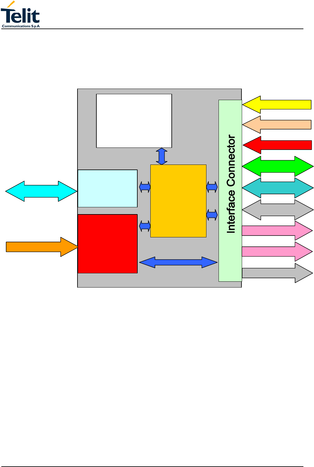
The block diagram in Figure 1 shows the interconnection between GM862-GPS
Transceiver and Other Equipment Manufacturer Hardware.
Figure 1 GM862-GPS Transceiver.
Internal
SIM
CARD
reader
QUAD BAND
RFsection
GPS section
GPS RF connector
RX-TX connector
Charger Input
Power supply
A
/D Connect
Camera Interface
GPIO 1-7
RS232 UART data
Handset AUDIO path
Handsfree AUDIO path
BB Processing
E-Gold Lite
RS232 NMEA data

TECHNICAL MANUAL
Telit GM862-GPS
Quad Band GPS Data Terminal Module
Pag.8 of 79
Rev. 0
3.1 GM862-GPS Transceiver Module
The GM862-GPS Transceiver Module is a Quad Band GSM - GPRS class 10 (4 down 2
up) based on Lite Infineon chipset and PV Lite internal SW platform with SiRF GSC3F
GPS chipset, on low profile compact shielded assembly with connections for GSM RX/TX
antenna, GPS antenna and data/service connector for all functional and interface signals.
The module is provided with an on board SIM Holder.
3.1.1 Electric Characteristics
3.1.1.1 Supply voltage
The external power supply must be connected to the VBATT signal and must fulfill the
following requirements:
• Nominal operating voltage: 3.8 V
• Operating voltage range: 3.4 V - 4.2 V
3.1.2 Power consumption
The typical current consumption of the GM862-GPS module is:
• Power off current (typical) < 36 μA;
• Stand–by current (power saving) < 20 mArms (< 5 mArms using command AT+CFUN)
• Operating current in voice ch. 170 mArms @ typical network conditions
• Operating current in voice ch. < 270 mArms 1.9 Apeak @ worst network conditions
• Operating current GPRS class 10 < 500 mArms @ worst network conditions
• GPS Receiver consumption < 60 mArms
• GPS Receiver (power saving) 1 mArms

TECHNICAL MANUAL
Telit GM862-GPS
Quad Band GPS Data Terminal Module
Pag.9 of 79
Rev. 0
3.1.3 Embodied Battery charger
The battery charger is suited for 3.7V Li-Ion rechargeable battery (suggested capacity 500-
1000mAh). The Charger needs only a CURRENT LIMITED power source input and
charges the battery directly through VBATT connector pins.
• Battery charger input pin: CHARGE
• Battery pins: VBATT, GND
• Battery charger input voltage min: 5.0 V
• Battery charger input voltage typ: 5.5 V
• Battery charger input voltage max: 7.0 V
• Battery charger input current max: 400mA
• Battery type: Rechargeable Li-Ion
NOTE: If embodied battery charger is used, then a LOW ESR capacitor of at least 100μF
must be mounted in parallel to VBATT lines.
NOTE: when power is supplied to the CHARGE lines, a battery must always be connected
to the VBATT pin of the module.

TECHNICAL MANUAL
Telit GM862-GPS
Quad Band GPS Data Terminal Module
Pag.10 of 79
Rev. 0
3.1.4 Radio Electric Characteristics
3.1.4.1 Operating frequencies
The standard operating frequencies are conforming to the ETSI GSM specifications.
Mode Freq. TX (MHz) Freq. RX (MHz) Channels (ARFC) TX - RX offset
E-GSM-900 890.0 - 914.8 935.0 - 959.8 0 – 124 45 MHz
880.2 - 889.8 925.2 - 934.8 975 - 1023 45 MHz
GSM-850 824.2 - 848.8 969.2 - 893.8 128 - 251 45 MHz
DCS-1800 1710.2 - 1784.8 1805.2 - 1879.8 512 – 885 95 MHz
PCS-1900 1850.2 - 1909.8 1930.2 - 1989.8 512 - 810 80 MHz
3.1.4.2 Transmitter output power
GSM–850
The GM862-GPS transceiver module in GSM–850 operating mode is class 4 in
accordance with the specification that set the nominal 2W peak RF power (+33dBm) on 50
Ohm.
GSM–900
The GM862-GPS transceiver module in GSM–900 operating mode is class 4 in
accordance with the specification that set the nominal 2W peak RF power (+33dBm) on 50
Ohm.
DCS–1800
The GM862-GPS transceiver module in DCS–1800 operating mode is class 1 in
accordance with the specifications that set the nominal 1W peak RF power (+30dBm) on
50 Ohm.
PCS–1900
The GM862-GPS transceiver module in PCS–1900 operating mode is class 1 in
accordance with the specifications that set the nominal 1W peak RF power (+30dBm) on
50 Ohm.
3.1.4.3 Reference sensitivity
GSM–850
The sensitivity of the GM862-GPS transceiver module according to the specifications for
the class 4 GSM–850 portable terminals is better than –102dBm in all the operational
conditions.
GSM–900
The sensitivity of the GM862-GPS Transceiver module according to the specifications, for
the class 4 GSM–900 portable terminals is better than –102dBm in all the operational
conditions. The static sensitivity is better than –105dBm in all the operational conditions.
DCS–1800
The sensitivity of the GM862- GPS Transceiver module according to the specifications, for
the class 1 portable terminals DCS 1800 is better than –102dBm in normal operating
conditions. The static sensitivity is better than –105dBm in all the operational conditions.
PCS–1900
The sensitivity of the GM862- GPS Transceiver module according to the specifications, for
the class 1 portable terminals PCS 1900 is better than –102dBm in normal operating
conditions. The static sensitivity is better than –105dBm in all the operational conditions.

TECHNICAL MANUAL
Telit GM862-GPS
Quad Band GPS Data Terminal Module
Pag.11 of 79
Rev. 0
3.2 Environmental requirements
The GM862-GPS module is compliant with the applicable ETSI reference documentation
GSM 05.05 Release 1999 ETSI EN300910 V8.4.1.
3.2.1 Climatic requirements
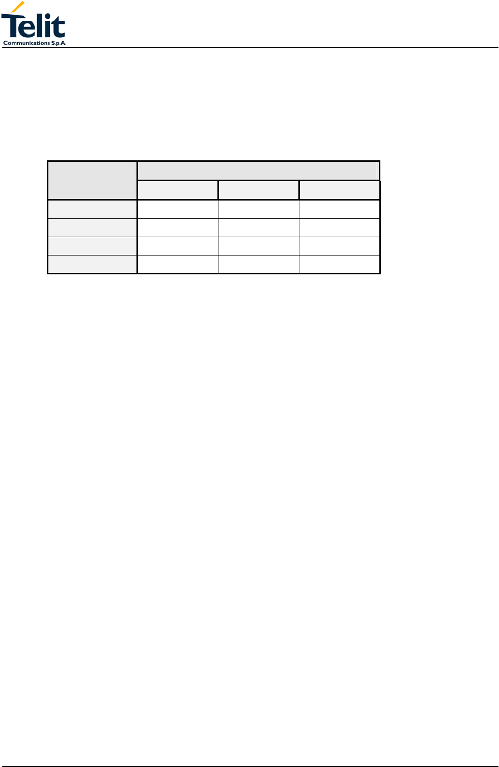
The table describes a set of environmental characteristics that the platform must satisfy:
Requirement IEC Test Condition
Functional temperature 60068-2-1 Ad Cold -25 °C
Functional temperature 60068-2-2 Bd Heat +75 °C
Not functional temperature 60068-2-1 Aa Cold -40 °C
Not functional temperature 60068-2-2 Ba Heat +85 °C
Not funct. Temp. Change 60068-2-14 Nb Change of
Temperature
5 cycles -25÷+30°C
Not functional dampness 60068-2-56 Cb Damp heat
steady state
93% UR at +40°C
3.2.2 Temperature range
• Temperature in normal functional conditions: –30°C ÷ +80°C
• Temperature in storage conditions: –30°C ÷ +85°C
3.2.3 Vibration Test (non functional)
• 10 ÷12Hz ASD = 1.92m 2 /s 3
• 12 ÷ 150Hz –3dB/oct
3.2.4 SIM Card Reader
The GM862-GPS Transceiver module supports a 3 volts small type SIM card, through the
internal SIM Card Reader or through the suitable signals on the interface connector pins.
TECHNICAL MANUAL
Telit GM862-GPS
Quad Band GPS Data Terminal Module
Pag.12 of 79
Rev. 0
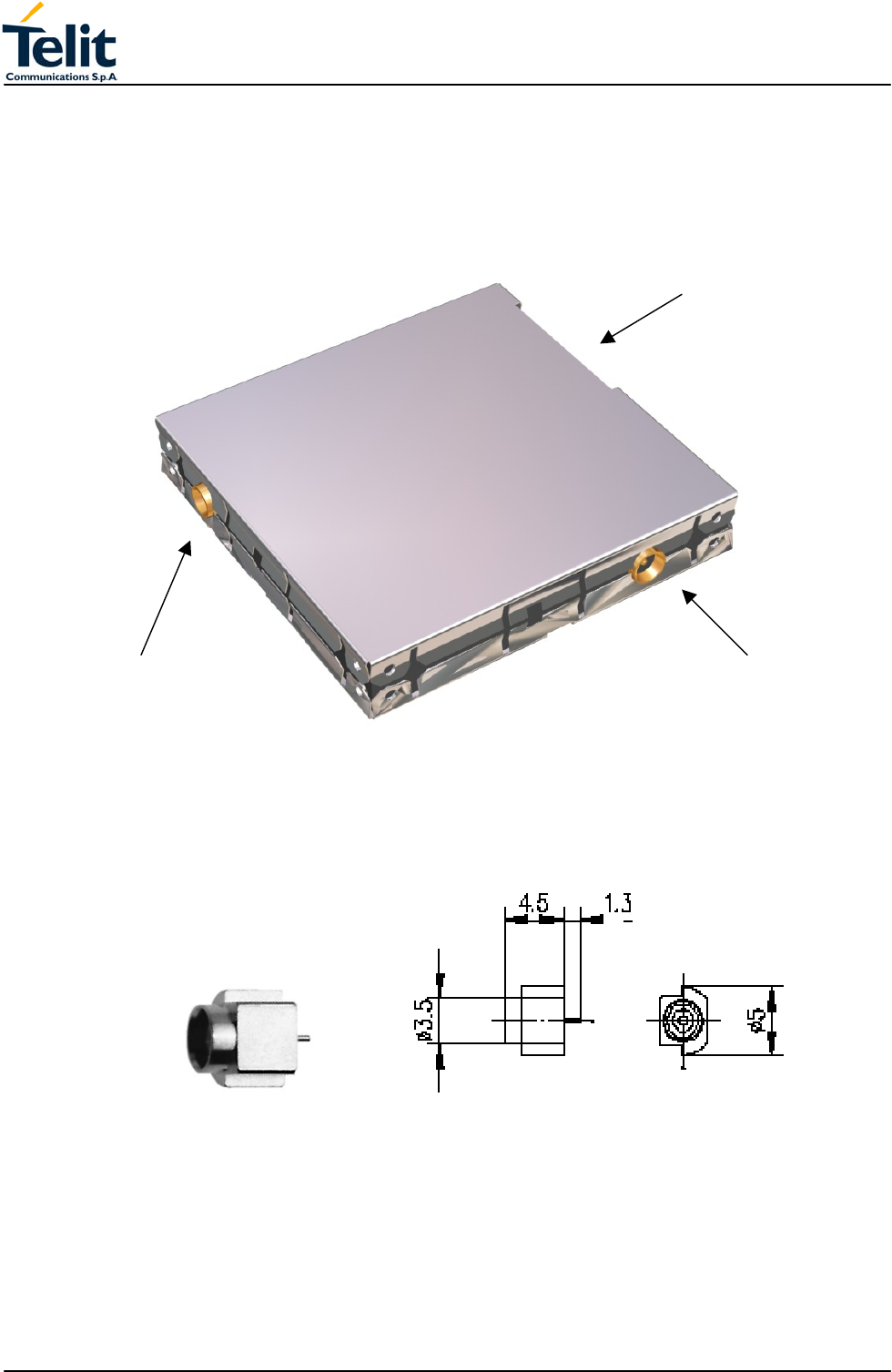
3.3 Transceiver module interface connectors
3.3.1 Antenna GSM-GPS connectors
The Telit GM862-GPS Transceiver module includes two 50 Ohm MMCX coaxial female 2
pin Angle Coax SMD J01341A0081 connectors to allow the GSM RF antenna and the
GPS antenna connection.
Picture 2: GSM and GPS Antenna coax connectors
GPS antenna
GSM antenna
SIM Holder connecto
r

TECHNICAL MANUAL
Telit GM862-GPS
Quad Band GPS Data Terminal Module
Pag.13 of 79
Rev. 0
3.3.2 GSM Antenna requirements
The GSM antenna that the customer chooses to use, depending on his application, should
fulfill the following requirements:
Frequency range Standard QUAD Band frequency range,
Bandwith 80 MHz in GSM & 170 MHz in DCS & 140 MHz PCS band
Gain 1.5dBi ≤ Gain < 3dBi
Impedance 50 ohm
Input power > 2 W peak power
VSWR absolute max <= 10:1
VSWR recommended <= 2:1
3.3.3 GPS Antenna requirements
The GPS antenna that the customer chooses to use, depending on his application, should
fulfill the following requirements:
Frequency range GPS = 1575.42MHz
Bandwith GPS band
Gain Typical 25dB (Max 27 dB)
Impedance 50 ohm
Supply voltage Nominal 3.8V range 3.4V up to 4.2V
Power consumption 40mA max
3.3.4 SIM Card connector
The Telit GM862-GPS Transceiver module includes two models of SIM CARD connector
one “Push-Push” connector for normal applications or a Hinged Cover connector for
automotive applications.
3.4 Audio levels specifications
The audio of the Telit GM862 GPS, module is organized into two main paths:
• internal path (called also MT)
• external path (called also HF)
These two paths are meant respectively for handset and headset/handsfree use.
The Telit GM862 GPS module has a built in echo canceller and a noise suppressor, tuned
separately for the two audio paths; for the internal path the echo canceller parameters are
suited to cancel the echo generated by a handset, while for the external audio path they
are suited for a handsfree use.
For more information on the audio refer to the Hardware User Guide.
The following tables report all the audio level specifications.

TECHNICAL MANUAL
Telit GM862-GPS
Quad Band GPS Data Terminal Module
Pag.14 of 79
Rev. 0
“Mic_MT” 1st differential microphone path
• line coupling AC
• line type balanced
• coupling capacitor ≥ 100nF
• differential input resistance 50kΩ
• differential input voltage ≤ 1,03Vpp (365mVrms)
• microphone nominal sensitivity -45 dBVrms/Pa
• analog gain suggested + 20dB
• echo canceller type handset
“Mic_HF” 2nd differential microphone path
• line coupling AC
• line type balanced
• coupling capacitor ≥ 100nF
• differential input resistance 50kΩ
• differential input voltage ≤ 65mVpp (23mVrms)
• microphone nominal sensitivity -45 dBVrms/Pa
• analog gain suggested +10dB
• echo canceller type car kit hands-free
Speaker characteristics
“Ear_MT” Differential Line-out Drivers Path
• line coupling: DC
• line type: bridged
• output load resistance : ≥ 14 Ω
• internal output resistance: 4 Ω (typical)
• signal bandwidth: 150 - 4000 Hz @ -3 dB
• max. differential output voltage 1310 mVrms (typ, open circuit)
• differential output voltage 328mVrms /16 Ω @ -12dBFS
• SW volume level step - 2 dB
• number of SW volume steps 10
“Ear_HF” Power Buffers path
• line coupling: DC
• line type: bridged
• output load resistance : ≥ 14 Ω
• internal output resistance: 4 Ω ( >1,7 Ω )
• signal bandwidth: 150 - 4000 Hz @ -3 dB
• max. differential output voltage 1310 mVrms (typ, open circuit)
• max. single ended output voltage 656 mVrms (typ, open circuit)
• SW volume level step - 2 dB
• number of SW volume steps 10

TECHNICAL MANUAL
Telit GM862-GPS
Quad Band GPS Data Terminal Module
Pag.15 of 79
Rev. 0
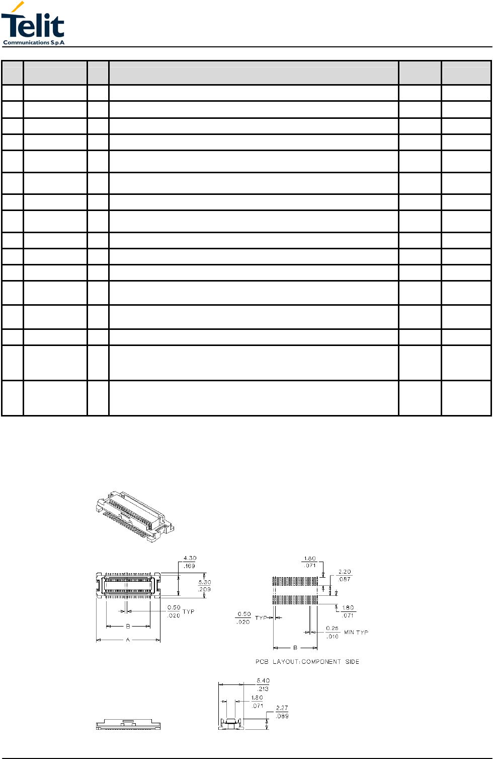
3.5 Interface connector
The GM862-GPS Transceiver module interface connector (Figure 3) is a low profile
0.50mm (.020") Pitch Receptacle - SMT, Dual Row, Vertical Stacking CSTP 50 pin Molex
52991–0508 (male) with the pin–out shown in the next table.
Pin Signal I/O Function Internal
Pull up Type
1 VBATT - Main power supply Power
2 GND - Ground Power
3 VBATT - Main power supply Power
4 GND - Ground Power
5 VBATT - Main power supply Power
6 A/D - A/D converter @ 12 bit (Input Impedance >100Kohm) Max 1V
input
7 VBATT - Main power supply Power
8 CHARGE AI Battery Charger Input (5) Power
9 EAR_HF+ AO Handsfree ear output, phase + Audio
10 EAR_MT- AO Handset earphone signal output, phase - Audio
11 EAR_HF- AO Handsfree ear output, phase - Audio
12 EAR_MT+ AO Handset earphone signal output, phase + Audio
13 MIC_HF- AI Handsfree microphone input; phase -, nominal level 3mVrms Audio
14 MIC_MT+ AI Handset microphone signal input; phase+, nominal level 50mVrms Audio
15 MIC_HF+ AI Handsfree microphone input; phase +, nominal level 3mVrms Audio
16 MIC_MT- AI Handset microphone signal input; phase-, nominal level 50mVrms Audio
17 ON_OFF I Input command for switching power ON or OFF (toggle command). The pulse to
be sent to the GM862 must be equal or greater than 1 second. 47K
Ω
Pull Up to
VBATT
18 AXE I Handsfree switching 100K
Ω
CMOS 2.8V
19 SIMIO I/O External SIM signal - Data I/O 3V ONLY
20 C103/TXD I Serial data input (TXD) from DTE CMOS 2.8V
21 PWRCTL O Module Status ON indication (Signal output for power on/off control of external
devices 1K
Ω
CMOS 2.8V
22 SIMVCC - External SIM signal – Power (3) 3V ONLY
23 RESET I Reset input
24 SIMRST O External SIM signal – Reset 3V ONLY
25 CAM_CLK I/O Camera Interface (4) CMOS 2.8V
26 SIMCLK O External SIM signal – Clock 3V ONLY
27 SIMIN I/O External SIM signal – Presence (active low) 47K
Ω
CMOS 2.8V
28 GPO2 / JDR O General purpose output (Open Collector) / Jammer Detect Report
Open
Collector
29 C106/CTS O Output for Clear to send signal (CTS) to DTE CMOS 2.8V
30 C125/RING O Output for Ring indicator signal (RI) to DTE CMOS 2.8V
31 GPI1 I General purpose input transistor
base
32 GPIO8/CAM_O
N I/O Configurable general purpose I/O pin / Camera Interface (4) CMOS 2.8V
33 C107/DSR O Output for Data set ready signal (DSR) to DTE CMOS 2.8V
34 GPIO9/CAM_RS
T I/O Configurable general purpose I/O pin / Camera Interface (4) CMOS 2.8V
TECHNICAL MANUAL
Telit GM862-GPS
Quad Band GPS Data Terminal Module
Pag.16 of 79
Rev. 0
Pin Signal I/O Function Internal
Pull up Type
35 TX_GPS O TX Data NMEA GPS protocol CMOS 2.8V
36 C109/DCD O Output for Data carrier detect signal (DCD) to DTE CMOS 2.8V
37 C104/RXD O Serial data output to DTE CMOS 2.8V
38 GPIO10/ CLK I/O Configurable general purpose I/O pin / TRACE or Python DEBUG (5) CMOS 2.8V
39 STAT_LED O Status indicator led Open
Collector
40 GPIO11 /
IIC_HW_SDA I/O Configurable general purpose I/O pin / IIC HW CMOS 2.8V
41 RX_GPS I RX Data NMEA GPS protocol CMOS 2.8V
42 GPIO12 /
IIC_HW_SCL I/O Configurable general purpose I/O pin / IIC HW interface CMOS 2.8V
43 C108/DTR I Input for Data terminal ready signal (DTR) from DTE (4) CMOS 2.8V
44 GPIO13 / MRST I/O Configurable general purpose I/O pin / TRACE or Python DEBUG (5) CMOS 2.8V
45 C105/RTS I Input for Request to send signal (RTS) from DTE CMOS 2.8V
46 GPIO3 / CAM_
SCL I/O Configurable general purpose I/O pin /
IIC Camera Interface (4) CMOS 2.8V
47 GPIO4 /
CAM_SDA I/O Configurable general purpose I/O pin /
IIC Camera Interface (4) CMOS 2.8V
48 GPIO5 / MTSR I/O Configurable general purpose I/O pin / TRACE or Python DEBUG (5) CMOS 2.8V
49
GPIO6
/ ALARM
I/O Configurable general purpose I/O pin /
ALARM CMOS 2.8V
50
GPIO7
/ BUZZER
I/O Configurable general purpose I/O pin /
BUZZER CMOS 2.8V
(1) For the exclusive use of the Technical Support Service
(2) An earphone with a 150 ohm impedance can be directly connected to EAR+ and EAR–
(3) On this pin a maximum of 47nF bypass capacitor is allowed.
(4) When activating the Easy camera these pins will not be available for other use
(5) This output requires an external circuit to connect it to a serial port.
Figure 3 Interface connector mechanical view

TECHNICAL MANUAL
Telit GM862-GPS
Quad Band GPS Data Terminal Module
Pag.17 of 79
Rev. 0
3.5.1 Logic level specification
Where not specifically stated, all the interface circuits work at 2.72V CMOS logic levels.
The following table shows the logic level specifications in the Telit GM862-QUAD/QUAD-
PY Transceiver module interface circuits:
LEVEL MIN MAX
Input high level 1.9 V 3.3 V
Input low level -0.2 V 0.5 V
Output high
level@1mA
2.15 V 2.8 V
Output low level
@1mA
0 V 0.2 V
Operating Range - Current Capability
Current Min Max
Current Output Low IOL - 1mA
Current Output High IOH - 1mA
Buffered Current Output High IBOH (2) - -
Buffered Current Output Low IBOL (2) 2mA 20mA
Buffered Current Input High IBIH (1) - 0.5mA
Buffered Current Input Low IBIL (1) - 30uA
(1) For GPIO1 pin - base input.
(2) For GPIO2 pin - Open Collector.
3.5.2 Reset signal
RESET is used to reset the Telit GM862-GPS Transceiver module. Whenever this signal is
pulled low, the GM862-GPS is reset and Re-booted.
CONNECTOR PIN I/O SIGNAL FUNCTION
SO301 23 I RESET Module reset and
Reboot
NOTE: do not use this signal to power off the Telit GM862-GPS module.
Use the ON/OFF signal (Pin 17 of SO301) to perform this function.
Signal levels:
SIGNAL MIN MAX
RESET Input high 2.2 V 3.3 V
RESET Input low 0 V 0.2 V
If unused, this signal may be left unconnected.
TECHNICAL MANUAL
Telit GM862-GPS
Quad Band GPS Data Terminal Module
Pag.18 of 79
Rev. 0
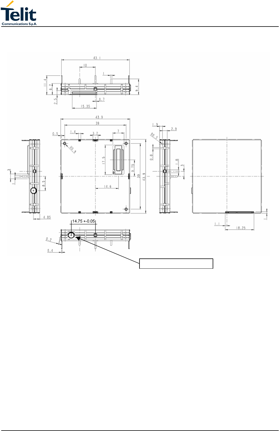
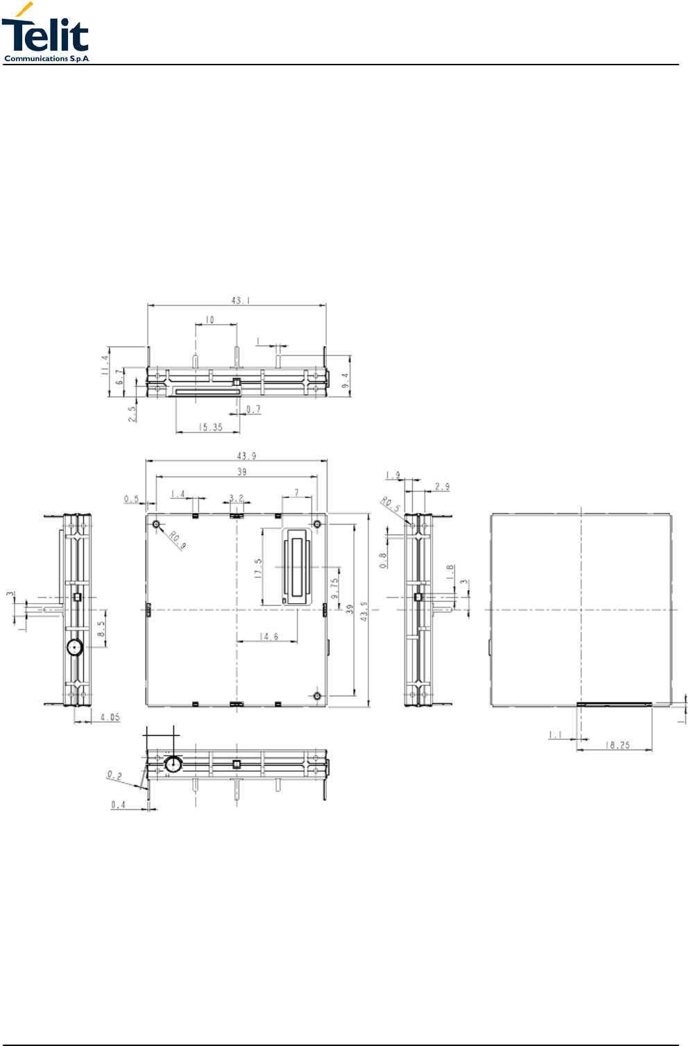
3.6 Mechanical characteristics
3.6.1 Dimensions
The Telit GM862-PCS module overall dimension are:
Length: 43.9 mm
Width: 43.9 mm
Thickness: 6.9 mm
Volume: ≅ 13 cm3
The mechanical layout of Telit GM862-GPS Transceiver module is shown in Figure 4
6.25
Figure 4 GM862-GPS Transceiver Mechanical layout
3.6.2 Weight
The Telit GM862-GPS module weight is 25gr, (shielding included).

TECHNICAL MANUAL
Telit GM862-GPS
Quad Band GPS Data Terminal Module
Pag.19 of 79
Rev. 0
3.7 GM862-GPS Data Terminal System
3.7.1 User Interface
The following features of GM862-GPS Data Terminal System user interface are managed
by AT commands specified on the GSM 07.07 and 07.05 specifications and listed in the
following.
3.7.2 Speech Coding
The vocoder of Telit GM862-GPS Data Terminal System supports the following rates:
• Half Rate.
• Full rate,
• Enhanced Full Rate;
3.7.3 SMS
The Telit GM862-GPS Data Terminal System supports the following SMS types:
• *Mobile Terminated (MT) class 0 – 2 with signaling of new incoming SMS, SIM full,
SMS read
• Mobile Originated class 0 – 3 with writing, memorize in SIM and sending
• *Cell Broadcast compatible with CB DRX with signaling of new incoming SMS.
3.7.4 Real Time Clock and Alarm
The Telit GM862-GPS module supports the Real Time Clock and Alarm functions through
AT commands; furthermore an alarm output pin (GPIO6) can be configured to indicate the
alarm with a hardware line output.
3.7.5 Data/fax transmission
The Telit GM862-GPS Data Terminal System supports:
• Packed Data transfer GPRS Class B, Multislot Class 10.
• Data transmission according to the GSM 07.07, 07.05
• CSD up to 14.4 Kbps
• Fax service, Class 1 Group 3
3.7.6 Local security management
With lock of Subscriber Identity module (SIM), and security code request at power–up.
3.7.7 Call control
Call cost control.
3.7.8 Phonebook
Function available to store the telephone number in SIM memory.
Capability depends on SIM version/memory.
3.7.9 Characters management
Availability of lowercase, uppercase and IRA characters. (international reference alphabet)
In SMS PDU mode all character set are supported.
3.7.10 SIM related functions
Activation/deactivation of the numbers stored in phone book FDN, ADN and PINs.
Extension at the PIN2 for the PUK2 insertion capability for lock condition.
3.7.11 Call status indication
By AT commands.
3.7.12 Indication of network service availability
By AT commands and LED indication on dedicated output.

TECHNICAL MANUAL
Telit GM862-GPS
Quad Band GPS Data Terminal Module
Pag.20 of 79
Rev. 0
The STAT_LED is an Open Collector output where it is possible to directly connect a LED
to show information on the network service availability and Call status.
STAT_LED indications
LED status Device Status
permanently off device off
fast blinking
(period 1s, Ton 0,5s)
Net search / Not registered /
turning off
slow blinking
(period 3s, Ton 0,3s)
Registered full service
permanently on a call is active
3.7.13 Automatic answer (Voice, Data or FAX)
After n (depends of settings) rings automatically answers with beep (see S0 parameter).
3.7.14 Supplementary services (SS)
• Call Barring,
• Call Forwarding,
• Calling Line Identification Presentation (CLIP),
• Calling Line Identification Restriction (CLIR),
• Call Waiting, other party call Waiting Indication,
• Call Hold, other party Hold / Retrieved Indication,
• Closed User Group supplementary service (CUG),
• Advice of Charge,
• Unstructured SS Mobile Originated (MO)
3.7.15 Acoustic signalling
The acoustic signaling on the selected acoustic device are the following:
• Call waiting;
• Ringing tone;
• SMS received tone;
• Busy tone;
• Power on/off tone;
• Off Hook dial tone;
• Congestion tone;
• Connected tone;
• Call dropped;
• No service tone;
• Alarm Tone.
TECHNICAL MANUAL
Telit GM862-GPS
Quad Band GPS Data Terminal Module
Pag.21 of 79
Rev. 0
3.7.16 DTMF tones
These standard DTMF tones (see table below) are generated by AT commands with
DTMF mode active and are corresponding to the keys from 0 to 9 and # , * of a keypad.
The minimum duration of a DTMF tone is 100ms.
Group low Group high (Hz)
(Hz) 1209 1336 1477
697 1 2 3
770 4 5 6
852 7 8 9
941 * 0 #
3.7.17 Buzzer output
The General Purpose I/O pin GPIO7 can be configured to output the BUZZER output
signal, with only an external Mosfet/transistor and a diode a Buzzer can be directly driven.
The ringing tone and the other signaling tones can be redirected to this Buzzer output with
a specific AT command.

TECHNICAL MANUAL
Telit GM862-GPS
Quad Band GPS Data Terminal Module
Pag.22 of 79
Rev. 0
3.8 EMC
Compliant to & ETS 300–342–1 and all applicable GSM Specifications.
Compliant to Directive 1999/05/CE.
3.9 Camera support
The GM862-GPS will provide a direct support for the camera whose characteristics are:
Model: TRANSCHIP TC5747
Technology: CMOS COLOR camera
Max picture size: VGA 640x480 pixels
Output format: JPEG
Sensitivity: 4V/lux-sec (including gain)
The camera will be directly managed by the GM862-GPS hardware/software with some
interface circuitry, providing a custom AT command interface to operate with it.
The camera interface requires the pins and GPIOs:
• CAM_SDA
• CAM_SCL
• CAM_CLK
• CAM_ON
• CAM_RST
When the camera is activated, then these pins are not accessible as GPIO.
The AT commands of the module permit to take a snapshot and successively download it
through the serial line in various formats.
TECHNICAL MANUAL
Telit GM862-GPS
Quad Band GPS Data Terminal Module
Pag.23 of 79
Rev. 0
3.10 Software Features
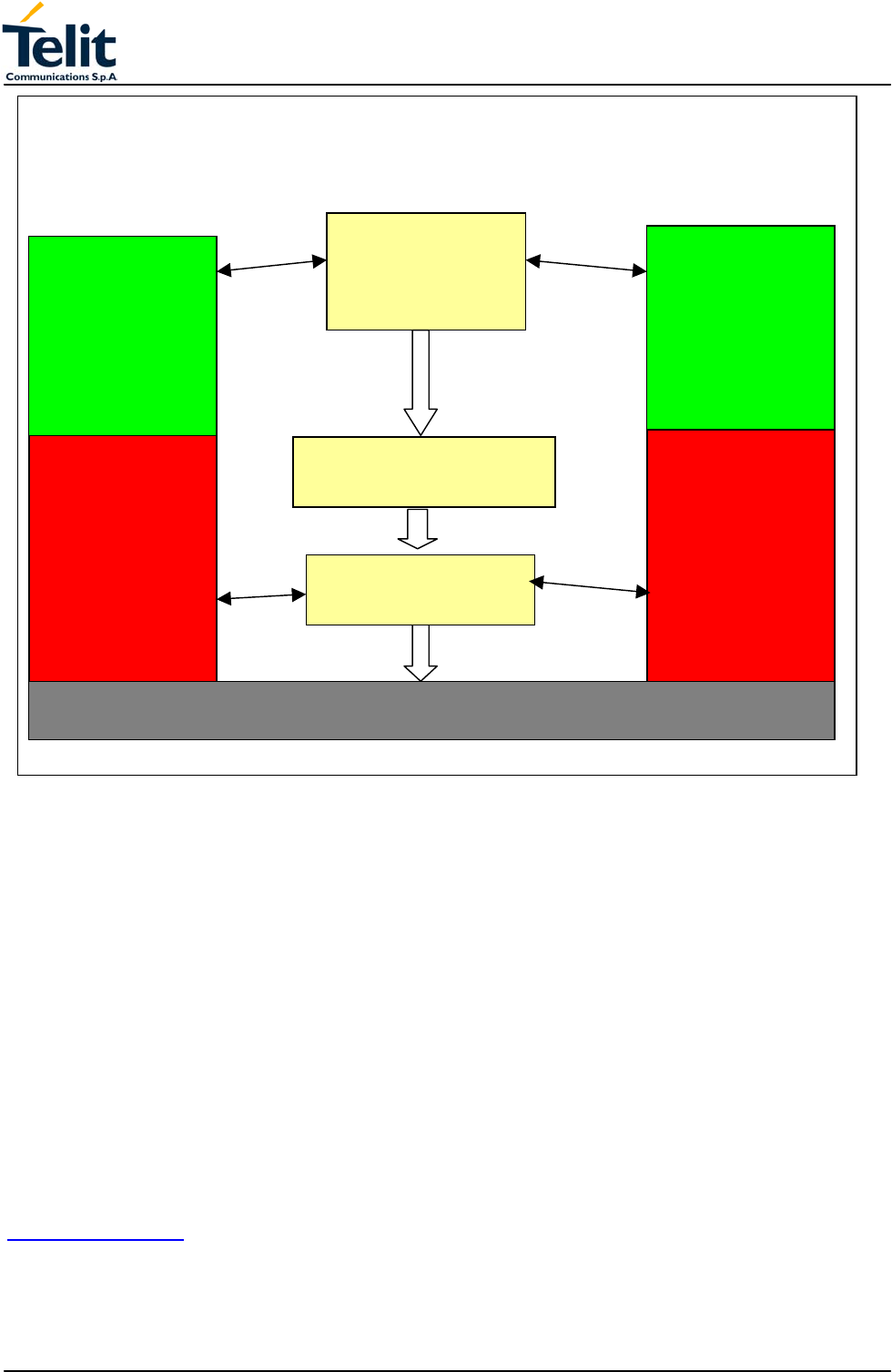
3.10.1 Enhanced Easy GPRS Extension
The Easy GPRS feature allows a Telit GM862-GPS user to contact a device in internet and
establish with it a raw data flow over the GPRS and Internet networks.
This feature can be seen as a way to obtain a "virtual" serial connection between the
Application Software on the Internet machine involved and the controller of the Telit
GM862-GPS module, regardless of all the software stacks underlying.
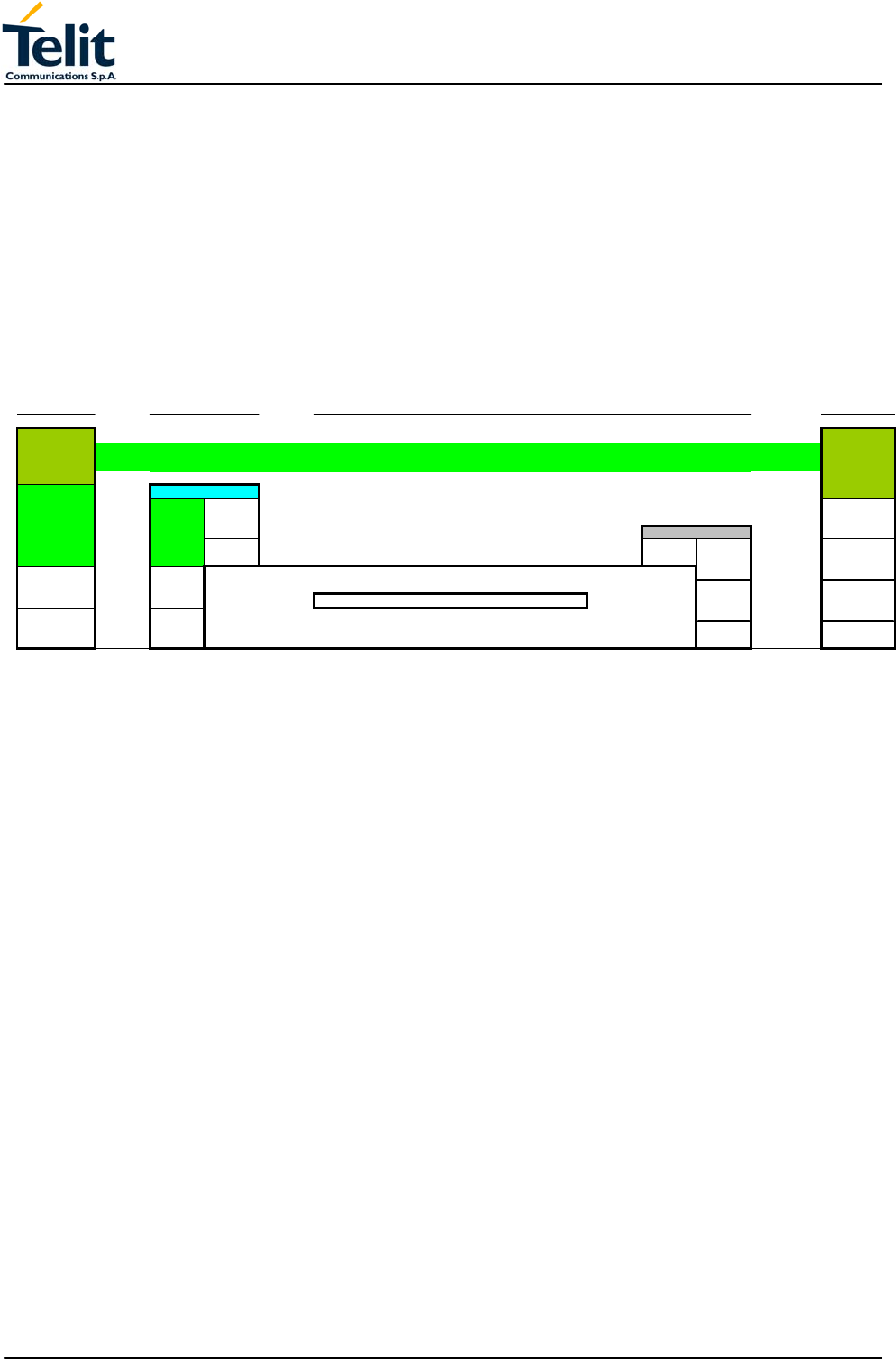
An example of the protocol stack involved in the devices is reported:
Figure 5 Enhance Easy GPRS Extension layout
This particular implementation allows to the devices interfacing to the Telit GM862-GPS
module the use of the GPRS and Internet packet service without the need to have an
internal TCP/IP stack since this function is embedded inside the module.
The new Enhanced version of the Easy GPRS overcomes some of the known limitations
of the previous implementation and implements some new features such as:
- Keep the GPRS context active even after the closing of a socket, allowing the
application to keep the same IP address;
- Also Mobile terminated (incoming) connections can be made, now it is possible to
receive incoming TCP connection requests;
- A new internal firewall has been implemented in order to guarantee a certain level of
security on internet applications.
-
3.10.2 Easy GPRS definition
The Easy GPRS feature provides a way to replace the need of an Internet TCP/IP stack at
the terminal equipment side. The steps that will be required to obtain a virtual serial
connection (that is actually a socket) to the Internet peer are:
a) configuring the GPRS Access
b) configuring the embedded TCP/IP stack behaviour
c) defining the Internet Peer to be contacted
d) request the GPRS and socket connections to be opened (host is connected)
e) exchange raw data
Remote
Controller Device
Device (Internet)
Local Remote
Application Application
TCP/UDP
EASY EASY TCP/UDP
GPRS GPRS
IP IP IP IP
Serial Data
Line on
Driver Board
L2 L2
V.24 V.24
L1 L1
Telit
GM862-GPS networks
Firewall
<<<---------------------------------- Virtual Serial link ---------------------------------->>>
network interworking

TECHNICAL MANUAL
Telit GM862-GPS
Quad Band GPS Data Terminal Module
Pag.24 of 79
Rev. 0
f) close the socket and GPRS context
All these steps are achieved through AT commands.
As for common modem interface, two logical status are involved: command mode and
data traffic mode.
- In Command Mode (CM), some AT commands are provided to configure the Data
Module Internet stack and to start up the data traffic.
- In data traffic mode (Socket Mode, SKTM), the client can send/receive a raw data
stream which will be encapsulated in the previously configured TCP / IP packets which
will be sent to the other side of the network and viceversa. Control plane of ongoing
socket connection is deployed internally to the module.
3.10.3 Configuring the GPRS access
The GPRS access configuration is done by setting:
- the GPRS context number 1 parameters (see +CGDCONT command)
- the Authentication parameters: User Name and Password (see commands #USERID,
#PASSW)
3.10.4 Configuring the embedded TCP/IP stack
The TCP/IP stack behaviour must be configured by setting:
- the packetizer default packet size (see command #PKTSZ)
- the data sending timeout (see command #DSTO)
- the socket inactivity timeout (see command #SKTTO)
3.10.5 Defining the Internet peer to be contacted
As last setting definition, the host to be contacted and on which port/protocol must be set :
- the socket definition (see command #SKTSET)
This command permits also to specify the host name instead of its IP address, if a host
name is given to the set command, then the module stores it as a host nick name. It is
care of the module user to guarantee that the host nick name provided corresponds to an
existing internet peer.
If an host nick name has been given then, while opening the connection in response to the
AT#SKTOP command, the module will autonomously activate a GPRS connection and
query its DNS to obtain the IP address relative to the host nick name provided. This
process of context activation and DNS query may require a bit more time and requires that
the GPRS network coverage is good enough to permit data transfers.
3.10.6 Open the connection with the internet host
With the AT#SKTOP all the process required to connect with the internet host starts:
- GM862-GPS activates the first context
- GM862-GPS proceeds to the authentication
- Eventually does the DNS query to resolve the IP address of the host name internet
peer
- GM862-GPS establishes a TCP/UDP (depending on the parameter request)
connection with the given internet host
- Once the connection is up the module reports the code: CONNECT
From this moment the data incoming in the serial port is packet and sent to the Internet
host, while the data received from the host is serialised and flushed to the Terminal
Equipment.

TECHNICAL MANUAL
Telit GM862-GPS
Quad Band GPS Data Terminal Module
Pag.25 of 79
Rev. 0
3.10.7 Close the Socket and deactivate the context
The connection can be closed because of:
- remote host TCP connection close
- socket inactivity timeout
- Terminal Equipment by issuing the escape sequence "+++"
- Network deactivation
Note: if in the raw data to be sent there's an escape sequence, then the TE must work it
out and sent it in a different fashion to guarantee that the connection is not closed.
The pause time is defined in the parameter S12.
On the reception of an escape sequence the GM862-GPS closes the connection,
deactivates the GPRS context returning to command mode and issuing the NO CARRIER
code.
3.10.8 Enhanced Easy GPRS Outgoing connection
The New Enhanced Easy GPRS feature provides a way to place outgoing TCP/UDP
connections and keep the same IP address after a connection, leaving the GPRS context
active.
The steps that will be required open a socket and close it without closing the GRPS
context are:
g) configuring the GPRS Access
h) configuring the embedded TCP/IP stack behaviour
i) defining the Internet Peer to be contacted
j) request the GPRS context to be activated
k) request the socket connection to be opened
l) exchange data
m) close the TCP connection while keeping the GPRS active
All these steps are achieved through AT commands.
As for common modem interface, two logical status are involved: command mode and
data traffic mode.
- In Command Mode (CM), some AT commands are provided to configure the Data
Module Internet stack and to start up the data traffic.
- In data traffic mode (Socket Mode, SKTM), the client can send/receive a raw data
stream which will be encapsulated in the previously configured TCP / IP packets which
will be sent to the other side of the network and viceversa. Control plane of ongoing
socket connection is deployed internally to the module.
3.10.8.1 Configuring the GPRS access
The GPRS access configuration is done by setting:
- the GPRS context number 1 parameters (see +CGDCONT command)
- the Authentication parameters: User Name and Password (see commands #USERID,
#PASSW)
3.10.8.2 Configuring the embedded TCP/IP stack
The TCP/IP stack behaviour must be configured by setting:
- the packetizer default packet size (see command #PKTSZ)
- the data sending timeout (see command #DSTO)

TECHNICAL MANUAL
Telit GM862-GPS
Quad Band GPS Data Terminal Module
Pag.26 of 79
Rev. 0
- the socket inactivity timeout (see command #SKTTO)
3.10.8.3 Defining the Internet peer to be contacted
As last setting definition, the host to be contacted and on which port/protocol must be set :
- the socket definition (see command #SKTSET)
This command permits also to specify the host name instead of its IP address, if a host
name is given to the set command, then the module stores it as a host nick name. It is
care of the module user to guarantee that the host nick name provided corresponds to an
existing internet peer.
If an host nick name has been given then, while opening the connection in response to the
AT#SKTOP command, the module will autonomously activate a GPRS connection and
query its DNS to obtain the IP address relative to the host nick name provided. This
process of context activation and DNS query may require a bit more time and requires that
the GPRS network coverage is good enough to permit data transfers.
Note that this setting command is not needed if the new #SKTD command is used.
3.10.8.4 Request the GPRS context to be activated
With the new command #GPRS you can activate or deactivate a GPRS context
INDEPENDENTLY from the TCP socket opening,
AT#GPRS=1 activates the context,
AT#GPRS=0 deactivates the context
Therefore with the AT#GPRS=1 command the module
- GM862-GPS activates the context previously defined with AT+CGDCONT
- GM862-GPS proceeds to the authentication
Note that activating a context implies getting an IP address from the network and this will
be maintained throughout the session.
The response code to the AT#GPRS=1 command reports the IP address obtained from
the network, allowing the user to report it to his server or application.
Deactivating the context implies freeing the network resources previously allocated to the
device.
3.10.8.5 Open the connection with the internet host
With the new command #SKTD (socket Dial) the TCP/UDP request to connect with the
internet host starts:
- Eventually does the DNS query to resolve the IP address of the host name internet
peer
- GM862-GPS establishes a TCP/UDP (depending on the parameter request)
connection with the given internet host
- Once the connection is up the module reports the code: CONNECT
Note that the peer specifications of this socket Dial are within the command and not the
one stored with #SKTSET command.
From this moment the data incoming in the serial port is packet and sent to the Internet
host, while the data received from the host is serialised and flushed to the Terminal
Equipment.

TECHNICAL MANUAL
Telit GM862-GPS
Quad Band GPS Data Terminal Module
Pag.27 of 79
Rev. 0
NOTE: this command differently from the AT#SKTOP DOES NOT automate all the
process of activating the GPRS, if no GPRS is active the command reports ERROR;
therefore before issuing this command the GPRS shall be activated with AT#GPRS=1
command.
In the same manner, when disconnecting the #SKTD command does not close the GPRS
context, leaving it active for next connections until an AT#GPRS=0 command is issued or
the network requests a context closing.
3.10.8.6 Close the Socket without deactivating the context
The connection can be closed because of:
- remote host TCP connection close
- socket inactivity timeout
- Terminal Equipment by issuing the escape sequence "+++"
- Network deactivation
Note: if in the raw data to be sent there's an escape sequence, then the TE must work it
out and sent it in a different fashion to guarantee that the connection is not closed.
The pause time is defined in the parameter S12.
On the reception of an escape sequence if the socket was opened with the AT#SKTD
command, the GM862-GPS closes the connection, does not deactivate the GPRS context
and returns to command mode issuing the NO CARRIER code.
3.10.9 Enhanced Easy GPRS Incoming Connection
The New Enhanced Easy GPRS feature provides a way to accept incoming TCP/UDP
connections and keep the same IP address after a connection, leaving the GPRS context
active.
The steps that will be required to open a socket in listen, waiting for connection requests
from remote hosts and accept these request connections only from a selected set of hosts,
then close it without closing the GRPS context are:
a) configuring the GPRS Access
b) configuring the embedded TCP/IP stack behaviour;
c) defining the Internet Peer that can contact this device (firewall settings)
d) request the GPRS context to be activated
e) request the socket connection to be opened in listen
f) receive connection requests
g) exchange data
h) close the TCP connection while keeping the GPRS active.
All these steps are achieved through AT commands.
As for common modem interface, two logical status are involved: command mode and
data traffic mode.
- In Command Mode (CM), some AT commands are provided to configure the Data
Module Internet stack and to start up the data traffic.
- In data traffic mode (Socket Mode, SKTM), the client can send/receive a raw data
stream which will be encapsulated in the previously configured TCP / IP packets which

TECHNICAL MANUAL
Telit GM862-GPS
Quad Band GPS Data Terminal Module
Pag.28 of 79
Rev. 0
will be sent to the other side of the network and viceversa. Control plane of ongoing
socket connection is deployed internally to the module.
3.10.9.1 Defining the Internet Peer that can contact this device (firewall settings)
The GM862-GPS has an internal Firewall that controls the behaviour of the incoming
connections to the module.
The firewall applies for INCOMING (listening) connections, OUTGOING connections will
be always done regardless of the firewall settings.
Firewall General policy is DROP, therefore all packets that are not included into an
ACCEPT chain rule will be silently discarded.
When a packet incomes from the IP address <incoming IP>, the firewall chain rules will be
scanned for matching with the following criteria:
<incoming IP> & <net mask> = <ip_address> ?
if the result is yes, then the packet is accepted and the rule scan is finished, otherwise the
next chain is taken into account until the end of the rules when the packet is silently
dropped if no matching was found.
For example, let assume we want to accept connections only from our devices which are
on the IP addresses ranging from :
197.158.1.1 to 197.158.255.255
We need to add the following chain to the firewall:
AT#FRWL=1,"197.158.1.1","255.255.0.0"
3.10.9.2 Request the socket connection to be opened in listen
With the new command #SKTL (socket Listen) the TCP request to start listening for
connection requests is executed:
- GM862-GPS opens a listening socket on the port specified, waiting for incoming TCP
connections (depending on the parameter request) with the internet hosts
The parameters that shall be specified are the local port where packets shall be received,
the type of socket and the closing behaviour.
3.10.9.3 Receiving connection requests
Once the connection request is received, the module reports an indication of connection
with an unsolicited code
+CONN FROM: <remote address>
- then connection is accepted and once it is up the module reports the code:
CONNECT
From this moment the data incoming in the serial port is packet and sent to the Internet
host, while the data received from the host is serialised and flushed to the Terminal
Equipment.

TECHNICAL MANUAL
Telit GM862-GPS
Quad Band GPS Data Terminal Module
Pag.29 of 79
Rev. 0
Note that the connections request are FIRST screened in the firewall, then if they are
accepted they pass to the listening socket; therefore only hosts that are in the ACCEPT
chain rules of the firewall can induce a connection request, the other host requests will be
silently discarded without any indication to the remote host (for security reasons).
Once the connection is received and closed, the socket is not anymore in listen. If the
application needs again to be in listen, then it shall send again the socket listen #SKTL
command.
NOTE: this command differently from the AT#SKTOP DOES NOT automate all the
process of activating the GPRS, if no GPRS is active the command reports ERROR;
therefore before issuing this command the GPRS shall be activated with AT#GPRS=1
command.
In the same manner, when disconnecting the #SKTL command does not close the GPRS
context, leaving it active for next connections until an AT#GPRS=0 command is issued or
the network requests a context closing.
3.10.10 Known limitations
The implementation of the EASY GPRS feature has the following known limitations:
- Only one socket can be opened at a time, no multiple socket connections can be
made;
- Only one connection request can be accepted at a time, subsequent requests will be
silently discarded.
- Only the first GPRS context is associated with this feature;
- It is taken for granted that external processor will be able to handle at least a limited
v.24 implementation: RTS, CTS and, highly recommended, DCD lines; this because
software flow control is not applicable to the feature;
- Due to the particularity of this feature, the flow control of both the directions uplink and
downlink is interlocked

TECHNICAL MANUAL
Telit GM862-GPS
Quad Band GPS Data Terminal Module
Pag.30 of 79
Rev. 0
3.11 Jammed Detect & Report Extension
3.11.1 Overview
The Jammed Detect & Report feature allows a Telit GM862-GPS to detect the presence of
a disturbing device such as a Communication Jammer and give indication to the user
and/or send a report of that to the network.
This feature can be very important in alarm, security and safety applications that rely on
the module for the communications. In these applications, the presence of a Jammer
device can compromise the whole system reliability and functionality and therefore shall be
recognized and reported either to the local system for countermeasure actions or to the
network providing remote actions.
An example scenario could be an intrusion detection system that uses the module for
sending the alarm indication for example with an SMS to the system owner, and a thief
incomes using a Jammer to prevent any communication between the GSM module and
the network.
In such a case, the module detects the Jammer presence even before the break in and
can trigger an alarm siren, other communication devices (PSTN modem) or directly report
this condition to the network that can provide further security services for example sending
SMS to the owner or police. Obviously this last service depends also from network
infrastructure support and some networks may not support it.
TECHNICAL MANUAL
Telit GM862-GPS
Quad Band GPS Data Terminal Module
Pag.31 of 79
Rev. 0
3.12 Easy Script Extension - Python interpreter
3.12.1 Overview
This feature is available only on the Telit GM862-GPS.
The Easy Script Extension is a feature that allows to drive the modem "internally" writing
the controlling application directly in a nice high level language: Python.
The Easy Script Extension is aimed at low complexity applications where the application
was usually done by a small microcontroller that managed some I/O pins and the GM862-
GPS through the AT command interface.
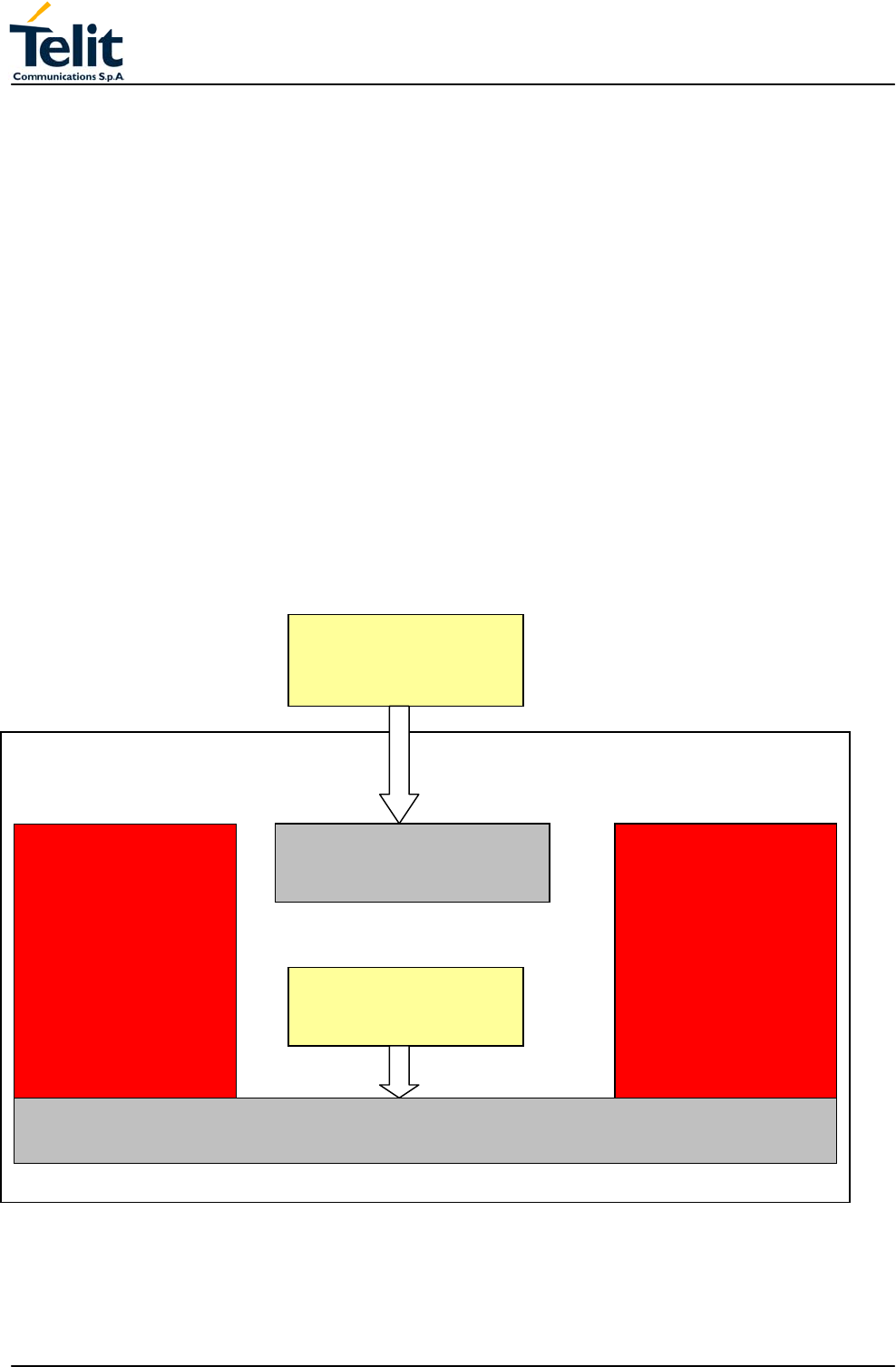
A schematic of such a configuration can be:
In order to eliminate this external controller, and further simplify the programming of the
sequence of operations, inside the GM862-GPS it is included:
- Python script interpreter engine v. 1.5.2+
- around 3MB of Non Volatile Memory room for the user scripts and data
- 1.5 MB RAM reserved for Python engine usage
A schematic of this approach is:
GM862-GPS
GSM-GPRS
Protocol Stack
FLASH ROM
memory
FLASH ROM
EXTERNAL
CONTROLLER
RAM
for
GSM-GPRS
modem
Protocol Stack
RAM
GPRS MODEM
ENGINE
PHYSICAL
AT SERIAL PORT
A
T COMMANDS
HARDWARE RESOURCES
TECHNICAL MANUAL
Telit GM862-GPS
Quad Band GPS Data Terminal Module
Pag.32 of 79
Rev. 0
GM862-GPS
GSM-GPRS
Protocol
Stack
FLASH ROM
memory
Available
User NVM
FLASH
Memory
(3Mbyte)
FLASH ROM PYTHON 1.5.2+
INTERPRETER
ENGINE
RAM
for
GSM-GPRS
modem
Protocol
Stack
Available
RAM for
Python
Interpreter
(1.5 Mbyte)
RAM
GPRS MODEM
ENGINE
VIRTUAL INTERNAL
AT SERIAL PORT
A
T COMMANDS
HARDWARE RESOURCES
MDM module
3.12.2 Python 1.5.2+ Copyright Notice
The Python code implemented into the GM862-GPS is copyrighted by Stichting
Mathematisch Centrum, this is the license:
Copyright © 1991-1995 by Stichting Mathematisch Centrum, Amsterdam, The
Netherlands.
All Rights Reserved
Permission to use, copy, modify, and distribute this software and its documentation for any
purpose and without fee is hereby granted, provided that the above copyright notice
appear in all copies and that both that copyright notice and this permission notice appear
in supporting documentation, and that the names of Stichting Mathematisch Centrum or
CWI or Corporation for National Research Initiatives or CNRI not be used in advertising or
publicity pertaining to distribution of the software without specific, written prior permission.
While CWI is the initial source for this software, a modified version is made available by
the Corporation for National Research Initiatives (CNRI) at the Internet address
ftp://ftp.python.org.
STICHTING MATHEMATISCH CENTRUM AND CNRI DISCLAIM ALL WARRANTIES
WITH REGARD TO THIS SOFTWARE, INCLUDING ALL IMPLIED WARRANTIES OF
MERCHANTABILITY AND FITNESS, IN NO EVENT SHALL STICHTING
MATHEMATISCH CENTRUM OR CNRI BE LIABLE FOR ANY SPECIAL, INDIRECT OR
TECHNICAL MANUAL
Telit GM862-GPS
Quad Band GPS Data Terminal Module
Pag.33 of 79
Rev. 0
CONSEQUENTIAL DAMAGES OR ANY DAMAGES WHATSOEVER RESULTING FROM
LOSS OF USE, DATA OR PROFITS, WHETHER IN AN ACTION OF CONTRACT,
NEGLIGENCE OR OTHER TORTIOUS ACTION, ARISING OUT OF OR IN
CONNECTION WITH THE USE OR PERFORMANCE OF THIS SOFTWARE.
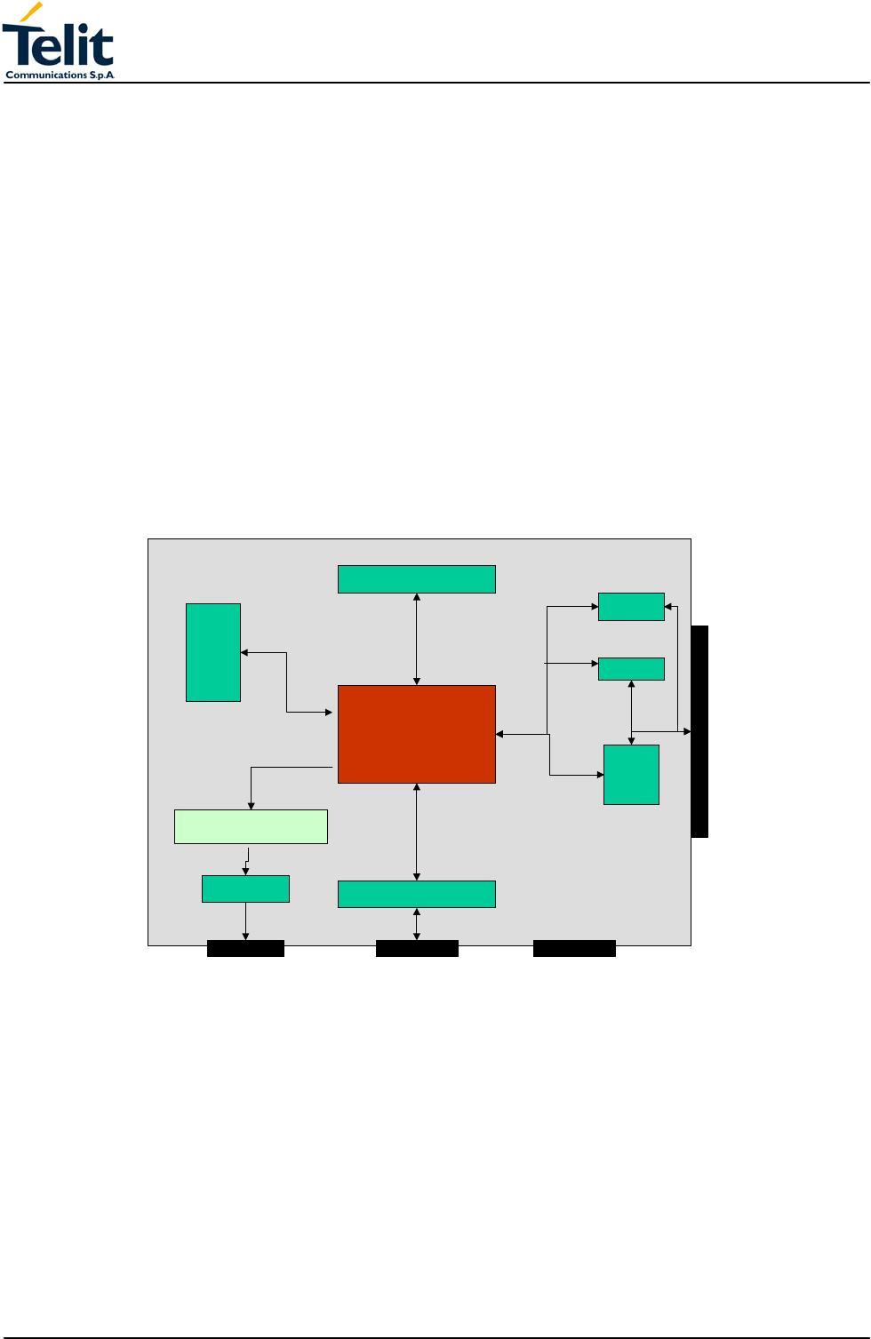
3.13 Python implementation description
Python scripts are text files, it is possible to run one Python script in the Telit GM862-GPS.
The Python script is stored in NVM inside the Telit GM862-GPS, there's a file system
inside the GM862-GPS that allows to write and read files with different names on one
single level (no subdirectories are supported).
The Python script is executed in a task inside the Telit GM862-GPS at the lowest priority,
making sure this does not interfere with GPRS/GSM normal operations. This allows serial
ports, protocol stack etc. to run independently from the Python script.
The Python script interacts with the Telit GM862-GPS Python functionality through four
build-in interfaces.
Python
engine
MDM
SER
MOD
GPIO
GM862-GPS
Serial port 0
GPIO
Serial port 1
Print command
IIC HW
SPI
IIC HW
IIC
Figure 6 Python script interaction scheme
The MDM interface is the most important one. It allows Python script to send AT
commands, receive responses and unsolicited indications, send data to the network and
receive data from the network during connections.
It is quite the same as the usual serial port interface in the Telit GM862-GPS. The
difference is that this interface is not a real serial port but just an internal software bridge
between Python and mobile internal AT command handling engine.
All AT commands working in the Telit GM862-GPS are working in this software interface
as well. Some of them have no meaning on this interface, such as those regarding serial
port settings.

TECHNICAL MANUAL
Telit GM862-GPS
Quad Band GPS Data Terminal Module
Pag.34 of 79
Rev. 0
The usual concept of flow control keeps its meaning over this interface, but it's managed
internally.
The SER interface allows Python script to read from and write to the REAL, physical serial
port where usually the AT command interface resides, for example to read NMEA
information from a GPS device. When Python is running this serial port is free to be used
by Python script because it is not used as AT command interface since the AT parser is
mapped into the internal virtual serial port. No flow control is available from Python on this
port.
The GPIO interface allows Python script to handle general purpose input output faster than
through AT commands, skipping the command parser and going directly to control the
pins.
The MOD interface is a collection of useful functions.
For the debug, the print command is directly forwarded on the IIC_HW (pin 40
IIC_HW_SDA and pin 42 IIC_HW_SCL).
3.13.1 Python core supported features
The Python core version is 1.5.2+ (string methods added to 1.5.2).
You can use all Python statements and almost all Python built-in types and functions.
The following are not supported:
complex; float; long; docstring.
Available modules are
marshal, imp, __main__, __builtin__, sys
md5
All the others are not supported.

TECHNICAL MANUAL
Telit GM862-GPS
Quad Band GPS Data Terminal Module
Pag.35 of 79
Rev. 0
3.13.2 Python Build-in Custom Modules
Several build in custom modules have been included in the python core, specifically aimed
at the hardware environment of the module.
The build in modules included are:
MDM: interface between Python and mobile internal AT command handling;
SER: interface between Python and mobile internal serial port ASC0 direct handling;
GPIO: interface between Python and mobile internal general purpose input output direct
handling;
MOD: interface between Python and mobile miscellaneous functions.
IIC: custom software Inter IC bus that can be mapped on creation over almost any GPIO
pin available.
SPI: custom software Serial Protocol Interface bus that can be mapped on creation over
almost any GPIO pin available.
GPS: custom software interface for GPS data stream coming from GPS chipset.
3.13.2.1 MDM built-in module
MDM built-in module is the interface between Python and the module AT command parser
engine.
You need to use MDM built-in module if you want to send AT commands from Python
script to the device and to receive responses from the device into your Python script.
Default start configuration is echo disabled (ATE0) and long form (verbose) return codes
(ATV1),
If you want to use MDM built-in module you need to import it first:
import MDM
then you can use MDM built-in module methods like in the following example:
a = MDM.send('AT', 0)
b = MDM.sendbyte(0x0d, 0)
c = MDM.receive(10)
which sends 'AT' and receives 'OK'.
More details about MDM built-in module methods are in the following paragraphs.
3.13.2.2 MDM.send(string, timeout)
Sends a string to AT command interface.
First input parameter string is a Python string which is the string to send to AT command
interface.
Second input parameter timeout is a Python integer which is the value in 1/10 s to wait for
the string to be sent to AT command interface before timeout expires. Waiting time is
caused by flow control.
Return value is a Python integer which is -1 if timeout expired otherwise is 1.
Example:
a = MDM.send('AT', 5)
sends string 'AT' to AT command handling, possibly waiting for 0.5 s, assigning return
value to a.

TECHNICAL MANUAL
Telit GM862-GPS
Quad Band GPS Data Terminal Module
Pag.36 of 79
Rev. 0
3.13.2.3 MDM.receive(timeout)
Receives a string from AT command interface waiting for it until timeout is expired.
Request to Send (RTS) is set to ON.
Input parameter timeout is a Python integer which is the value in 1/10 s to wait for a string
from AT command interface before timeout expires.
Return value is a Python string which is an empty string if timeout expired without any data
received otherwise is the string containing data received.
Example:
a = MDM.receive(15)
receives a string from AT command handling, possibly waiting for it for 1.5 s, assigning
return value to a.
3.13.2.4 MDM.read()
Receives a string from AT command interface without waiting for it. Request to Send
(RTS) is set to ON.
No input parameter.
Return value is a Python string which is an empty string if no data received otherwise is
the string containing data received.
Example:
a = MDM.read()
receives a string from AT command handling, assigning return value to a.
3.13.2.5 MDM.sendbyte(byte, timeout)
Sends a byte to AT command interface.
First input parameter byte is a Python byte which is any byte value to send to AT
command interface. It can be zero.
Second input parameter timeout is a Python integer which is the value in 1/10 s to wait for
the byte to be sent to AT command interface before timeout expires. Waiting time is
caused by flow control.
Return value is a Python integer which is -1 if timeout expired otherwise is 1.
Example:
b = MDM.sendbyte(0x0d, 0)
sends byte 0x0d, that is CR, to AT command handling, without waiting, assigning return
value to b.
3.13.2.6 MDM.receivebyte(timeout)
Receives a byte from AT command interface waiting for it until timeout is expired. Request
to Send (RTS) is set to ON.
Input parameter timeout is a Python integer which is the value in 1/10 s to wait for a byte
from AT command interface before timeout expires.
Return value is a Python integer which is -1 if timeout expired without any data received
otherwise is the byte value received. It can be zero.
Example:
b = MDM.receivebyte(20)
receives a byte from AT command handling, possibly waiting for it for 2.0 s, assigning
return value to b.

TECHNICAL MANUAL
Telit GM862-GPS
Quad Band GPS Data Terminal Module
Pag.37 of 79
Rev. 0
3.13.2.7 MDM.readbyte()
Receives a byte from AT command interface without waiting for it. Request to Send (RTS)
is set to ON.
No input parameter.
Return value is a Python integer which is -1 if no data received otherwise is the byte value
received. It can be zero.
Example:
b = MDM.readbyte()
receives a byte from AT command handling, assigning return value to b.
3.13.2.8 MDM.getDCD()
Gets Carrier Detect (DCD) from AT command interface.
No input parameter.
Return value is a Python integer which is 0 if DCD is OFF or 1 if DCD is ON.
Example:
cd = MDM.getDCD()
gets DCD from AT command handling, assigning return value to cd.
3.13.2.9 MDM.getCTS()
Gets Clear to Send (CTS) from AT command interface.
No input parameter.
Return value is a Python integer which is 0 if CTS is OFF or 1 if CTS is ON.
Example:
cts = MDM.getCTS()
gets CTS from AT command handling, assigning return value to cts.
3.13.2.10 MDM.getDSR()
Gets Data Set Ready (DSR) from AT command interface.
No input parameter.
Return value is a Python integer which is 0 if DSR is OFF or 1 if DSR is ON.
Example:
dsr = MDM.getDSR()
gets DSR from AT command handling, assigning return value to dsr.
3.13.2.11 MDM.getRI()
Gets Ring Indicator (RI) from AT command interface.
No input parameter.
Return value is a Python integer which is 0 if RI is OFF or 1 if RI is ON.
Example:
ri = MDM.getRI()
gets RI from AT command handling, assigning return value to ri.
3.13.2.12 MDM.setRTS()
Sets Request to Send (RTS) in AT command interface.
Input parameter is a Python integer which is 0 if setting RTS to OFF or 1 if setting RTS to
ON.
No return value.

TECHNICAL MANUAL
Telit GM862-GPS
Quad Band GPS Data Terminal Module
Pag.38 of 79
Rev. 0
Example:
MDM.setRTS(1)
sets RTS to ON in AT command handling.
3.13.2.13 MDM.setDTR()
Sets Data Terminal Ready (DTR) in AT command interface.
Input parameter is a Python integer which is 0 if setting DTR to OFF or 1 if setting DTR to
ON.
No return value.
Example:
MDM.setDTR(0)
sets DTR to OFF in AT command handling.
3.13.3 SER built-in module
SER built-in module is the interface between Python core and the device serial port over
the RXD/TXD pins direct handling.
You need to use SER built-in module if you want to send data from Python script to serial
port and to receive data from serial port ASC0 to Python script.
This serial port handling module can be used for example to interface the module with an
external device such as a GPS and read/send it's data (NMEA for example).
If you want to use SER built-in module you need to import it first:
import SER
then you can use SER built-in module methods like in the following example:
a = SER.SetSpeed('9600')
b = SER.send('test')
c = SER.sendbyte(0x0d)
d = SER.receive(10)
which sends 'test' followed by CR and receives data waiting for one second.
More details about SER built-in module methods are in the following paragraphs.
3.13.3.1 SER.send(string)
Sends a string to the serial port TXD/RXD.
Input parameter string is a Python string which is the string to send to serial port ASC0.
Return value is a Python integer which is -1 if an error occurred otherwise is 1.
Example:
a = SER.send('test')
sends string 'test' to serial port ASC0 handling, assigning return value to a.
3.13.3.2 SER.receive(timeout)
Receives a string from serial port TXD/RXD waiting for it until timeout is expired.
Input parameter timeout is a Python integer which is the value in 1/10 s to wait for a string
from serial port before timeout expires.
Return value is a Python string which is an empty string if timeout expired without any data
received otherwise is the string containing data received.
Example:
a = SER.receive(15)

TECHNICAL MANUAL
Telit GM862-GPS
Quad Band GPS Data Terminal Module
Pag.39 of 79
Rev. 0
receives a string from serial port handling, waiting for it for 1.5 s, assigning return value to
a.
3.13.3.3 SER.read()
Receives a string from serial port TXD/RXD without waiting for it.
No input parameter.
Return value is a Python string which is an empty string if no data received otherwise is
the string containing data received.
Example:
a = SER.read()
receives a string from serial port handling, assigning return value to a.
3.13.3.4 SER.sendbyte(byte)
Sends a byte to serial port TXD/RXD.
Input parameter byte is a Python byte which is any byte value to send to serial port. It can
be zero.
Return value is a Python integer which is -1 if an error occurred otherwise is 1.
Example:
b = SER.sendbyte(0x0d)
sends byte 0x0d, that is CR, to serial port handling, assigning return value to b.
3.13.3.5 SER.receivebyte(timeout)
Receives a byte from serial port TXD/RXD waiting for it until timeout is expired.
Input parameter timeout is a Python integer which is the value in 1/10 s to wait for a byte
from serial port before timeout expires.
Return value is a Python integer which is -1 if timeout expired without any data received
otherwise is the byte value received. It can be zero.
Example:
b = SER.receivebyte(20)
receives a byte from serial port handling, waiting for it for 2.0 s, assigning return value to b.
3.13.3.6 SER.readbyte()
Receives a byte from serial port TXD/RXD without waiting for it.
No input parameter.
Return value is a Python integer which is -1 if no data received otherwise is the byte value
received. It can be zero.
Example:
b = SER.readbyte()
receives a byte from serial port handling, assigning return value to b.
3.13.3.7 SER.SetSpeed(speed, <char format>)
Sets serial port TXD/RXD speed. Default serial port TXD/RXD speed is 9600.
Input parameter speed is a Python string which is the value of the serial port speed. It can
be the same speeds as the +IPR command.
NOTE: sending the +IPR command to the device is not affecting the physical serial, when
using Python engine you must use this function to set the speed of the port.
Optional Parameter <char format> is a Python string that represents the character format
to be used:

TECHNICAL MANUAL
Telit GM862-GPS
Quad Band GPS Data Terminal Module
Pag.40 of 79
Rev. 0
first is the number of bits per char (7 or 8), then the parity setting (N - none, E- even, O-
odd) and the number of stop bits (1 or 2). Default is "8N1"
Return value is a Python integer which is -1 if an error occurred otherwise is 1.
Example:
b = SER.SetSpeed('115200')
sets serial port speed to 115200, assigning return value to b.
3.13.4 GPIO built-in module
GPIO built-in module is the interface between Python core and module internal general
purpose input output direct handling.
You need to use GPIO built-in module if you want to set GPIO values from Python script
and to read GPIO values from Python script.
You can control GPIO pins also by sending internal 'AT#GPIO' commands using the MDM
module, but using the GPIO module is faster because no command parsing is involved,
therefore it's use is suggested.
Note that Python core does not verify if the pins are already used for other purposes (IIC
module or SPI module) by other functions, it's the applicator responsibility to ensure that
no conflict over pins occurs.
If you want to use GPIO built-in module you need to import it first:
import GPIO
then you can use GPIO built-in module methods like in the following example:
a = GPIO.getIOvalue(5)
b = GPIO.setIOvalue(4, 1)
which reads GPIO 5 value and sets GPIO 4 to output with value 1.
More details about GPIO built-in module methods are in the following paragraphs.
3.13.4.1 GPIO.setIOvalue(GPIOnumber, value)
Sets output value of a GPIO pin.
First input parameter GPIOnumber is a Python integer which is the number of the GPIO.
Second input parameter value is a Python integer which is the ouput value. It can be 0 or
1.
Return value is a Python integer which is -1 if an error occurred otherwise is 1.
Example:
b = GPIO.setIOvalue(4, 1)
sets GPIO 4 to output with value 1, assigning return value to b.
3.13.4.2 GPIO.getIOvalue(GPIOnumber)
Gets input or output value of a GPIO.
Input parameter GPIOnumber is a Python integer which is the number of the GPIO.
Return value is a Python integer which is -1 if an error occurred otherwise is input or
output value. It is 0 or 1.
Example:
a = GPIO.getIOvalue(5)
gets GPIO 5 input or output value, assigning return value to b.
3.13.4.3 GPIO.setIOdir(GPIOnumber, value, direction)
Sets direction of a GPIO.
First input parameter GPIOnumber is a Python integer which is the number of the GPIO.

TECHNICAL MANUAL
Telit GM862-GPS
Quad Band GPS Data Terminal Module
Pag.41 of 79
Rev. 0
Second input parameter value is a Python integer which is the ouput value. It can be 0 or
1. It is only used if direction value is 1.
Third input parameter value is a Python integer which is the direction value. It can be 0 for
input or 1 for output.
Return value is a Python integer which is -1 if an error occurred otherwise is 1.
Example:
c = GPIO.setIOdir(4, 0, 0)
sets GPIO 4 to input with value having no meaning, assigning return value to c.
3.13.4.4 GPIO.getIOdir(GPIOnumber)
Gets direction of a GPIO.
Input parameter GPIOnumber is a Python integer which is the number of the GPIO.
Return value is a Python integer which is -1 if an error occurred otherwise is direction
value. It is 0 for input or 1 for output.
Example:
d = GPIO.getIOdir(7)
gets GPIO 7 direction, assigning return value to d.
3.13.5 MOD built-in module
MOD built-in module is the interface between Python and module miscellaneous functions.
You need to use MOD built-in module if you want to generate timers in Python script, to
reactivate Python from Python script, etc.
If you want to use MOD built-in module you need to import it first:
import MOD
then you can use MOD built-in module methods like in the following example:
MOD.reactivatePython()
which reactivates Python after next exiting from Python script.
More details about MOD built-in module methods are in the following paragraphs.
3.13.5.1 MOD.secCounter()
Returns seconds elapsed since 1 January 1970.
This method is useful for timers generation in Python script.
No input parameter.
Return value is a Python integer which is the value of seconds elapsed since 1 January
1970.
Example:
a = MOD.secCounter()
returns seconds elapsed since 1 January 1970.
3.13.5.2 MOD.sleep(sleeptime)
Blocks Python script execution for a given time returning the resources to the system.
Input parameter timesleep is a Python integer which is the time in 1/10 s to block script
execution.
No return value.
Example:
MOD.sleep(15)
blocks Python script for 1.5 s.

TECHNICAL MANUAL
Telit GM862-GPS
Quad Band GPS Data Terminal Module
Pag.42 of 79
Rev. 0
3.13.5.3 MOD.reactivatePython()
Reactivates Python script after exiting from actual Python script.
This method is useful for Python script restart.
The effect of this method is to restart the complete procedure of selecting the Python script
to be executed and of executing it.
If you want this method to have the expected effect you need to exit actual Python script
as soon as possible after calling it (for example braking while or for loops).
No input parameter.
No return value.
Example:
MOD.reactivatePython()
reactivates Python after next exiting from Python script.
3.13.6 IIC built-in module
IIC built-in module is an implementation on the Python core of the IIC bus Master (No
Multi-Master) using the "bit-banging" technique.
You need to use IIC built-in module if you want to create one or more IIC bus on the
available GPIO pins. This IIC bus handling module is mapped on creation on two GPIO
pins that will become the Serial Data and Serial Clock pins of the bus. It can be multi-
instantiated (you can create more than one IIC bus over different pins) and the pins used
must not be used for other purposes.
Note that Python core does not verify if the pins are already used for other purposes (SPI
module or GPIO module) by other functions, it's the applicator responsibility to ensure that
no conflict over pins occurs.
If you want to use IIC built-in module you need to import it first:
import IIC
then you can create the new bus over the GPIO pins (for example over the pins GPIO3,
GPIO4) and then use IIC built-in module methods like in the following example:
IICbus = IIC.new(3,4)
IICbus.init()
res = IICbus.send('test')
c = IICbus.sendbyte(0x0d)
d = IICbus.readbyte()
which sends 'test' followed by CR and receives data waiting for one second.
NOTE that you must provide external pull-up on SDA line since the line is working as open
collector, SCLK instead is driven with a complete push pull.
More details about IIC built-in module object methods are in the following paragraphs.
3.13.6.1 IIC.new(SDA_pin, SCL_pin)
Creates a new IIC bus object on the GPIO pins number.
Input parameter SDA_pin, SCL_pin are Python bytes which are the GPIO pin number
where the SDA (Serial DAta) and SCL (Serial CLock) lines are mapped.
Return value is the Python custom IIC bus object pointer which then shall be used to
interface with the IIC bus created.
Example:
bus1 = IIC.new(3,4)

TECHNICAL MANUAL
Telit GM862-GPS
Quad Band GPS Data Terminal Module
Pag.43 of 79
Rev. 0
bus2 = IIC.new(5,6)
This creates two IIC bus, one over the GPIO3 and GPIO4 and one over the GPIO5 and
GPIO6.
Available pins for the IIC bus are GPIO3 - GPIO13, while GPIO1 and GPIO2 are not
available for IIC.
3.13.6.2 IIC object method: init()
Does the first pin initialisation on the IIC bus previously created.
Return value is a Python integer which is -1 if an error occurred otherwise is 1.
Example:
a = bus1.init()
3.13.6.3 IIC object method: sendbyte(byte)
Sends a byte to the IIC bus previously created.
Input parameter byte is a Python byte which is the byte to be sent to the IIC bus.
The start and stop condition on the bus are added by the function.
Return value is a Python integer which is -1 if an error occurred otherwise is 1 the byte has
been acknowledged by the slave.
Example:
a = bus1.sendbyte(123)
sends byte 123 to the IIC bus , assigning return result value to a.
3.13.6.4 IIC object method: send(string)
Sends a string to the IIC bus previously created.
Input parameter string is a Python string which is the string to send to the IIC bus.
Return value is a Python integer which is -1 if an error occurred otherwise is 1 if all bytes
of the string have been acknowledged by the slave.
Example:
a = bus1.send('test')
sends string 'test' to the IIC bus , assigning return result value to a.
3.13.6.5 IIC object method: dev_read(addr, len)
Receives a string of len bytes from IIC bus device at address addr.
Return value is a Python string which is containing data received.
Example:
a = bus1.read(114,10)
receives a string of 10 bytes from IIC bus device at address 114, assigning it to a.
3.13.6.6 IIC object method: dev_write(addr, string)
Sends a string to the IIC bus device at address addr.
Return value is a Python string which is 1 if data is acknowledged correctly, -1 otherwise.
Example:
a = bus1.dev_write(114,'123456789')
sends the string '123456789' to the IIC bus device at address 114, assigning the result to
a.
3.13.6.7 IIC object method: dev_gen_read(addr, start, len)
Receives a string of len bytes from IIC bus device whose address is addr, starting from
address start.

TECHNICAL MANUAL
Telit GM862-GPS
Quad Band GPS Data Terminal Module
Pag.44 of 79
Rev. 0
Return value is a Python string which is containing data received.
Example:
a = bus1.read(114,122, 10)
receives a string of 10 bytes from IIC bus device at address 114, starting from address 122
assigning it to a.
3.13.6.8 IIC object method: dev_gen_write(addr, start, string)
Sends a string to the IIC bus device whose address is addr, starting from address start.
Return value is a Python string which is 1 if data is acknowledged correctly, -1 otherwise.
Example:
a = bus1.dev_write(114,, 112, '123456789')
sends the string '123456789' to the IIC bus device at address 114, starting from address
start, assigning the result to a.
3.13.7 SPI built-in module
SPI built-in module is an implementation on the Python core of the SPI bus Master using
the "bit-banging" technique.
You need to use SPI built-in module if you want to create one or more SPI bus on the
available GPIO pins. This SPI bus handling module is mapped on creation on three or
more GPIO pins that will become the Serial Data In/Out and Serial Clock pins of the bus,
plus a number of optional chip select pins up to 8. It can be multi-instantiated (you can
create more than one SPI bus over different pins) and the pins used must not be used for
other purposes.
Note that Python core does not verify if the pins are already used for other purposes (IIC
module or GPIO module) by other functions, it's the applicator responsibility to ensure that
no conflict over pins occurs.
If you want to use SPI built-in module you need to import it first:
import SPI
then you can create the new bus over the GPIO pins (for example over the pins GPIO3,
GPIO4, GPIO5 ) and then use SPI built-in module methods like in the following example:
SPIbus = SPI.new(3,4,5)
SPIbus.init(0,0)
res = SPIbus.send('test')
c = SPIbus.sendbyte(0x0d)
d = SPIbus.readbyte()
which sends 'test' followed by CR and receives data waiting for one second.
More details about SPI built-in module object methods are in the following paragraphs.
3.13.7.1 SPI.new(SCLK_pin, MOSI_pin, MISO_pin, <SS0>, <SS1>,…<SS7>)
Creates a new SPI bus object on the GPIO pins number corresponding.
Input parameter SCLK_pin, MOSI_pin and MISO_pin are Python bytes which are the
GPIO pin number where the SCLK (Serial CLocK), MOSI (Master Output Slave Input),
MISO (Master Input Slave Output) lines are mapped. The same is for the SS0 .. SS9
which are OPTIONAL Python bytes which are the GPIO pin number where the

TECHNICAL MANUAL
Telit GM862-GPS
Quad Band GPS Data Terminal Module
Pag.45 of 79
Rev. 0
corresponding Slave Select line is mapped. Up to 8 slave select lines can be defined (also
none if only 1 slave is used).
Return value is the Python custom SPI bus object pointer which then shall be used to
interface with the SPI bus created.
Example:
bus3 = SPI.new(3,4,5)
bus4 = SPI.new(6,7,8,9,10)
This creates two SPI bus, one over the GPIO3, GPIO4, GPIO5 and one over the GPIO6,
GPIO7, GPIO8, GPIO9, GPIO10 where the GPIO9 is the Slave 0 select and GPIO10 is the
Slave 1 select pin.
Available pins for the SPI bus are GPIO3 - GPIO13, while GPIO1 and GPIO2 are not
available for SPI.
3.13.7.2 SPI object method: init(CPOL, CPHA)
Does the first pin initialisation on the SPI bus previously created.
Bus clock polarity is controlled by CPOL value:
CPOL = 0 - clock polarity low
CPOL = 1 - clock polarity high
Bus clock phase transmission is controlled by CPHA value:
CPHA = 0 - data bit is clocked/latched on the first edge of the SCLK.
CPHA = 1 - data bit is clocked/latched on the second edge of the SCLK.
Return value is a Python integer which is -1 if an error occurred otherwise is 1.
Example:
a = bus3.init(0,0)
3.13.7.3 SPI object method: sendbyte(byte, <SS_number>)
Sends a byte to the SPI bus previously created addressed for the Slave number
SS_number whose Slave Select signal is activated.
Input parameter byte is a Python byte which is the byte to be sent to the SPI bus.
Optional Parameter SS_number is a Python byte representing the Slave number to be
activated, if not present no slave line is activated.
Return value is a Python integer which is -1 if an error occurred otherwise is 1 the byte has
been sent.
Example:
a = bus3.sendbyte(123)
sends byte 123 to the SPI bus , assigning return result value to a.
b=bus4.sendbyte(111,1)
sends byte 111 to the SPI bus activating the Slave Select line of the SS1 device (in our
example GPIO10)
3.13.7.4 SPI object method: send(string, <SS_number>)
Sends a string to the SPI bus previously created.
Input parameter string is a Python string which is the string to send to the SPI bus.
Optional Parameter SS_number is a Python byte representing the Slave number to be
activated, if not present no slave line is activated.

TECHNICAL MANUAL
Telit GM862-GPS
Quad Band GPS Data Terminal Module
Pag.46 of 79
Rev. 0
Return value is a Python integer which is -1 if an error occurred otherwise is 1 if all bytes
of the string have been sent.
Example:
a = bus3.send('test')
sends string 'test' to the SPI bus , assigning return result value to a.
3.13.7.5 SPI object method: read(len, <SS_number>)
Receives a string of len bytes from SPI bus device at Slave Select number SS_number.
Optional Parameter SS_number is a Python byte representing the Slave number to be
activated, if not present no slave line is activated.
Return value is a Python string which is containing data received.
Example:
a = bus4.read(10,0)
receives a string of 10 bytes from SPI bus device on SS0 line, assigning it to a.
3.13.7.6 SPI object method: readwrite(string, len, <SS_number>)
Send the string "string" and contemporaneously receives a string of len bytes from SPI bus
device at Slave Select number SS_number.
Optional Parameter SS_number is a Python byte representing the Slave number to be
activated, if not present no slave line is activated.
Return value is a Python string which is containing data received.
Example:
a = bus4.readwrite("hello",10,0)
send the string "hello" and receives a string of 10 bytes from SPI bus device on SS0 line,
assigning it to a.
3.13.8 GPS built-in module
GPS built-in module is an implementation on the Python core of the GPS data stream
parser.
This module have a set of functions that permit to get the information provided by the GPS
chipset.

TECHNICAL MANUAL
Telit GM862-GPS
Quad Band GPS Data Terminal Module
Pag.47 of 79
Rev. 0
3.13.9 Executing a Python script
The steps required to have a script running by the python engine of the module are:
- write the python script
- download the python script into the module NVM
- enable the python script
- execute it..
3.13.10 Write Python script
A Python script is a simple text file, it can be written with any text editor but for your
convenience a complete Integrated Development Environment (IDE) is included in a
software package that Telit provides called Telit Python Package.
Remembering the supported features described in 3.13.1, it is simple to write the script
and test it directly from the IDE.
The following is the "Hello Word" short Python script that sends the simplest AT command
to the AT command parser and waits for response, then ends.
import MDM
print 'Hello World!'
result = MDM.send('AT\r', 0)
print result
c = MDM.receive(10)
print c
3.13.11 Download Python script
The Script can be downloaded in the module using the #WSCRIPT command.
In order to guarantee your company know-how, you have the option to Hide the script text
so that the #RSCRIPT command does not return the text of the script and keeps it
"confidential", you can see only the name of the script with the #LSCRIPT command.
Remember that if you chose to hide the script text it's your responsibility to keep
information on what is executing the module, for example by naming the script depending
from the application and version of the script.
In order to download the script, first you have to choose a name for your script in the
module taking care that:
- it must have extension .py;
- the maximum allowed length is 16 characters;
- script name is case sensitive.
Then you have to find out the exact size in bytes of the script (for example right clicking on
the file and selecting “properties”)
The script download is done regardless the previous serial settings at 115200 baud 8-N-1
with hardware flow control active.
For example (script name and size are examples):
AT#WSCRIPT=”a.py”,110
wait for the prompt
>>>
and use “Send Text file” with ASCII Setup: Send line ends with line feeds in
HyperTerminal enabled.

TECHNICAL MANUAL
Telit GM862-GPS
Quad Band GPS Data Terminal Module
Pag.48 of 79
Rev. 0
Wait for download result: OK.
3.13.12 Enable Python script
Select the Python script which will be executed (the enabled script) from the next start-up
and on using the AT#ESCRIPT command.
First choose the script you want to enable between the ones you downloaded:
AT#LSCRIPT? can help you checking the names of the scripts;
for example:
AT#ESCRIPT=”a.py”
Wait for enable result: OK.
3.13.13 Execute Python script
The Python script you downloaded to module and enabled is executed at every module
power on if the DTR line is sensed LOW (2.8V at the GM862-GPS DTR pin - RS232
signals are inverted -) at start-up, (then no AT command interface is connected to the
modem port) and if the script name you enabled matches one of the script names of the
scripts you downloaded.
The Python script is executed with –v -S -OO options.
In order to gain again the AT command interface on the modem physical port (for example
to update locally a new script) the module shall be powered on with the DTR line HIGH (0V
at the GM862-GPS DTR pin) so that the script is not executed and the Python engine is
stopped.
The real execution of the Python script is delayed from the power on due to the time
needed by Python to parse the script. The longer is the script, the longer is this delay.
Note that only the running script is compiled at run time, all the others that this script may
include are compiled once and the compiled result is saved in the NVM as a file with
extension .pyo.
This delay can be greatly reduced with a simple stratagem:
- type your script normally, and include the main loop in a function, for example
"main()", save it to the NVM of the module with a known name, for example appl.py
- write a new script that includes the previous file object, for example "include appl",
and this file should call only the main function of the appl.py script, for example
appl.main().
In this way the first time the script is executed the imported files will be compiled and the
result saved as compiled .pyo files (don't delete them during normal operations, but
remember to delete them if you change the corresponding .py script otherwise your
changes will not take effect). From the next start-up and on the imported files will not be
anymore compiled and script execution delay is greatly reduced.
This stratagem is useful also for long complex scripts, that may run out of memory during
compilation; splitting the script into several smaller scripts containing part of the
functions/objects definitions will separate the compilation and allow for much bigger
script usage.

TECHNICAL MANUAL
Telit GM862-GPS
Quad Band GPS Data Terminal Module
Pag.49 of 79
Rev. 0
3.13.14 Debug Python script
The debug of the active Python script can be done both on the emulated environment of
the Telit Python Package (refer to its documentation) or directly on the SSC port (available
on pins 38, 44 and 48 ).
Now you can see all Python outputs to stdout and stderr:
- Python information messages (for example the version);
- Python error information;
- results of all Python “print” statements.
NOTE : In order to decode the strings sent out on SSC port is necessary to use an
external adapter and a special SW (Python Debug).

TECHNICAL MANUAL
Telit GM862-GPS
Quad Band GPS Data Terminal Module
Pag.50 of 79
Rev. 0
3.14 AT Commands
The Telit GM862 Family modules can be driven via the serial interface using the standard AT
commands1. The Telit GM862 Family modules are compliant with:
1. Hayes standard AT command set, in order to maintain the compatibility with existing
SW programs.
2. ETSI GSM 07.07 specific AT command and GPRS specific commands.
3. ETSI GSM 07.05 specific AT commands for SMS (Short Message Service) and
CBS (Cell Broadcast Service)
4. FAX Class 1 compatible commands
Moreover the Telit GM862 Family modules supports also Telit proprietary AT commands for
special purposes.
The following table lists all supported AT commands and related brief description.
The GM862 Family AT Command Description document, code 80264ST10013a, shows a
dedicated detailed description of all supported AT commands and how to use the AT
commands with the Telit GM862 Family modules through some example scripts.
Hayes Compliant AT Commands Type
Generic Modem Control GM862-GPS
&F Reset base section factory profile configuration •
&F1 Reset full factory profile configuration •
Z Soft reset •
+FCLASS Select active service class •
&Y Designate a default reset basic profile •
&P Designate a default reset full profile •
&W Store current configuration •
&Z Store telephone number in the internal phonebook •
&N Display internal phonebook stored numbers •
+GMI Request manufacturer identification •
+GMM Request model identification •
+GMR Request revision identification •
+GCAP Request capabilities list •
+GSN Request serial number •
&V Display current configuration & profile •
&V0 Display current configuration & profile •
&V1 Display S registers values •
&V2 Display last connection statistics •
&V3 Display S registers values •
\V Single line connect message •
%L Report line signal level •
%Q Report line quality •
+GCI Select the country of installation •
L Monitor speaker loudness •
M Monitor speaker mode •
1 The AT is an ATTENTION command and is used as a prefix to other parameters in a
string. The AT command combined with other parameters can be set up in the
communications package or typed in manually as a command line instruction.

TECHNICAL MANUAL
Telit GM862-GPS
Quad Band GPS Data Terminal Module
Pag.51 of 79
Rev. 0
DTE - modem interface control GM862-GPS
E Command echo •
Q Quiet resut codes •
V Result code form •
X Extended result codes •
I Request identifier and software checksum •
&C Data carrier detect (DCD) control •
&D Data terminal ready (DTR) control •
&K Flow control •
&Q Sync/async mode •
&S Data set ready (DSR) control •
\R Ring (RI) control •
+IPR Fixed DTE interface rate •
+IFC DTE - DTA flow control •
+ILRR DTE - modem rate reporting •
+ICF DTE - modem character format •
Call Control GM862-GPS
D Dial •
T Set tone dial •
P Set pulse dial •
A Answer •
A/ Last command automatic repetition •
H Disconnect •
O Return to On Line Mode •
&G Guard tone •
Modulation control GM862-GPS
+MS Modulation control •
%E Enable/disable line quality monitor and auto retrain
or fallback / fallforward •
\N Operating mode •
Compression control GM862-GPS
+DS Set data compression •
+DR Data compression reporting •
Break control GM862-GPS
\B Transmit break to remote •
\K Break handling •
S parameters GM862-GPS
S0 Number of rings to auto answer •
S1 Ring counter •
S2 Escape character •
S3 Carriage return character •
S4 Line feed character •
S5 Backspace character •
S7 Wait time for carrier, silence or dial tone •
S12 Escape prompt delay •
S25 Delay to DTR off •
S30 Disconnect inactivity timer •
S38 Delay before forced hang up •
ETSI GSM 07.07 AT Commands GM862-GPS
+CGMI Request manufacturer identification •
+CGMM Request model identification •
+CGMR Request revision identification •

TECHNICAL MANUAL
Telit GM862-GPS
Quad Band GPS Data Terminal Module
Pag.52 of 79
Rev. 0
+CGSN Request product serial number identification •
+CSCS Select TE character set •
+CIMI Request international mobile subscriber identity
(IMSI) •
Call control GM862-GPS
+CBST Select bearer service type •
+CRLP Radio link protocol •
+CR Service reporting control •
+CEER Extended error report •
+CRC Cellular result codes •
+CSNS Single numbering scheme •
Network service handling GM862-GPS
+CNUM Subscriber number •
+COPN Read operator names •
+CREG Network registration report •
+COPS Operator selection •
+CLCK Facility lock/ unlock •
+CPWD Change facility password •
+CLIP Calling line identification presentation •
+CLIR Calling line identification restriction •
+CCFC Call forwarding number and conditions •
+CCWA Call waiting •
+CHLD Call holding services •
+CUSD Unstructured supplementary service data •
+CAOC Advice of charge •
+CLCC List current calls •
+CSSN SS Notification •
+CCUG Closed User Group supplementary service control •
Mobile Equipment control GM862-GPS
+CPAS Phone activity status •
+CFUN Set phone functionality (Power Saving Management) •
+CPIN Enter PIN •
+CSQ Signal quality •
+CPBS Select phonebook memory storage •
+CPBR Read phonebook entries •
+CPBF Find phonebook entries •
+CPBW Write phonebook entry •
+CCLK Clock Management •
+CALA Alarm Management •
+CALM Alert sound mode •
+CRSL Ringer sound level •
+CLVL Loudspeaker volume level •
+CMUT Microphone mute control •
+CACM Accumulated call meter •
+CAMM Accumulated call meter maximum •
+CPUC Price per unit and currency table •
Mobile equipment errors GM862-GPS
+CMEE Report mobile equipment error •
Voice Control (TIA IS-101) GM862-GPS
+VTS: DTMF tones transmission •
Commands For GPRS GM862-GPS
+CGACT PDP context activate or deactivate •

TECHNICAL MANUAL
Telit GM862-GPS
Quad Band GPS Data Terminal Module
Pag.53 of 79
Rev. 0
+CGATT GPRS attach or detach •
+CGDATA Enter data state •
+CGDCONT Define PDP context •
+CGPADDR Show PDP address •
+CGREG GPRS network registration status •
+CGQMIN Quality of service profile (minimum acceptable) •
+CGQREQ Quality of service profile (requested) •
Commands For Battery Charger GM862-GPS
+CBC Battery Charge •
ETSI GSM 07.05 AT Commands for SMS and CB services GM862-GPS
+CSMS Select message service •
+CPMS Preferred message storage •
+CMGF Message format •
+CSMP Set parameters in text mode •
+CSDH Show parameters in text mode •
+CSAS Save setting text mode •
+CRES Restore text mode settings •
+CSCB Select Cell Broadcast Message types •
Message configuration GM862-GPS
+CSCA Service center address •
Message receiving and reading GM862-GPS
+CNMI New message indications to Terminal Equipment •
+CMGL List messages •
+CMGR Read message •
Message sending and writing GM862-GPS
+CMGS Send message •
+CMSS Send message from storage •
+CMGW Write message to memory •
+CMGD Delete message •
Custom AT Commands GM862-GPS
#CGMI Request manufacturer identification •
#CGMM Request model identification •
#CGMR Request revision identification •
#CGSN Request product serial number identification •
#CIMI Request international mobile subscriber identity
(IMSI) •
#CAP Change Audio Path •
#SRS Select ringer sound •
#SRP Select Ringer Path •
#STM Signalling Tones Mode •
#PCT Display PIN Counter •
#SHDN Software Shut Down •
#WAKE Wake from Alarm mode •
#QTEMP Query Temperature overflow •
#SGPO Set General Purpose Output •
#GGPI Read General Purpose Input •
#GPIO General Purpose Input/Output pin control •
#MONI Monitor Cells •
#QSS Query SIM Status •
#ACAL Set Automatic Call •
#SMOV SMS Overflow •
#SHFEC Set Handsfree echo canceller •

TECHNICAL MANUAL
Telit GM862-GPS
Quad Band GPS Data Terminal Module
Pag.54 of 79
Rev. 0
#HFMICG Handsfree Microphone Gain •
#HSMICG Handset Microphone Gain •
#SHFSD Set Handsfree side tone •
#/ Repeat last command •
#BND Select Band •
FAX Class 1 Commands GM862-GPS
+FCLASS Select active service class •
+FMI Report manufacturer ID •
+FMM? Report model ID •
+FMR Report revision ID •
Transmission/Reception control GM862-GPS
+FTS Stop Transmission and pause •
+FRS Wait for receive silence •
+FTM Transmit data modulation •
+FRM Receive data modulation •
+FTH Transmit data with HDLC framing •
+FRH Receive data with HDLC framing •
Serial port control GM862-GPS
+FLO Select flow control specified by type •
+FPR Select serial port rate •
+FDD Double escape character replacement control •
Enhanced Easy GPRS custom AT command Definition GM862-GPS
#USERID Authentication User ID control •
#PASSW Authentication Password control •
#PKTSZ Packet Size control •
#DSTO Data Sending TimeOut control •
#SKTTO Socket inactivity timeout control •
#SKTSET Socket definition control •
#SKTOP Socket Open command •
#QDNS Query DNS •
#SKTCT Socket TCP Connection Timeout •
#SKTSAV Socket Parameters Save Command •
#SKTRST Socket Parameters Reset Command •
#GPRS GPRS context activation control •
#SKTD Socket Dial •
#SKTL Socket Listen •
#FRWL Firewall setup •
Easy Camera Extension - Camera Management GM862-GPS
#CAMON Camera ON •
#CAMOFF Camera OFF •
#TPHOTO Camera Take Photo •
#RPHOTO Camera Read Photo •
#OBJL Object List •
#OBJR Object Read •
#CAMQUA Camera Select Quality of Photo •
#CMODE Camera Select Operating MODE •
Email management GM862-GPS
#ESMTP Email SMTP server •
#EADDR Email sender address •
#EUSER Email authentication USER NAME •
#EPASSW Email authentication PASSWORD •
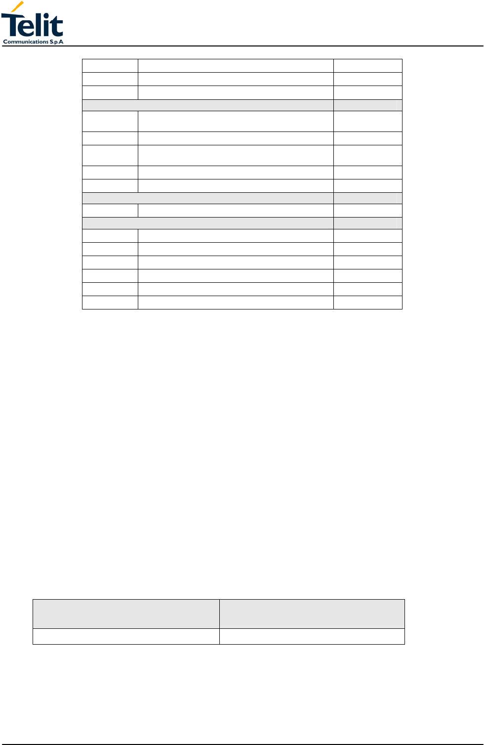
TECHNICAL MANUAL
Telit GM862-GPS
Quad Band GPS Data Terminal Module
Pag.55 of 79
Rev. 0
#SEMAIL Send Email •
#ESAV Email Parameters Save Command •
#ERST Email Parameters Reset Command •
Easy Scan Extension GM862-GPS
#CSURV Network Survey of the complete 900/1800/1900
Network •
#CSURVC Network Survey in computer friendly format •
#CSURVU Network Survey of user defined 900/1800/1900
chan. •
#CSURVUC Network Survey in computer friendly format •
#CSURVF Network Survey Format •
Jammed Detect & Report custom AT command GM862-GPS
#JDR Jammed Detect & Report •
PYTHON Script Management commands GM862-GPS
#WSCRIPT Write script command •
#ESCRIPT Select Active script command •
#RSCRIPT Read script command •
#LSCRIPT List script names command •
#DSCRIPT Delete script command •
#REBOOT Reboot command •
3.15 GPS Receiver characteristic
The main features of SiRFstarIII GPS chipset (GSC3f) are the following:
High sensitivity for indoor fixes (-158 dBm)*
Extremely fast TTFFs at low signal levels
Hot starts < 2 seconds
SBAS (WAAS and EGNOS) support
Compatible with autonomous and aided software
200,000+ effective correlators
Supports 20-Channel GPS
* Depending on the used GPS antenna.
3.15.1 Key Performance Specifications
The specifications in this section are intended to provide guidance regarding typical
system performance for cellular systems incorporating the GSC3F
3.15.1.1 Sensitivity
Type of Fix Minimum Signal Strength
(Signal Condition For All Satellites)
Hot Start (first fix after standby) -158 dBm
3.15.1.2 Average Power Consumption
- GPS Receiver consumption < 60 mArms
- GPS Receiver (power saving) 1 mArms
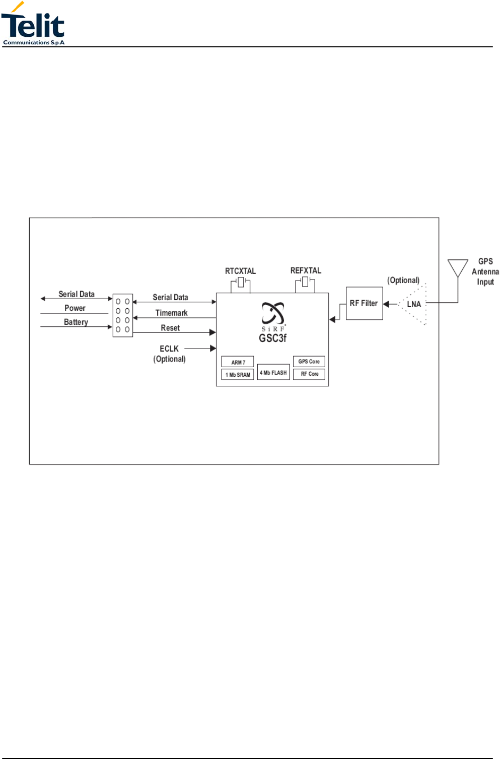
TECHNICAL MANUAL
Telit GM862-GPS
Quad Band GPS Data Terminal Module
Pag.56 of 79
Rev. 0
3.15.1.3 GPS driving
The GPS functions are driven from GSM BB microprocessor trough dedicated AT
command described in a internal document: see par 2.1 of this document.
3.15.1.4 GPS NMEA
The GPS data stream is also available on the connector (pins 35 and 41 : TX_GPS
and RX_GPS) in RS232 format 8 N 1 (4800, 9600, 19200, 38400, and 57600 Baud
Rates)
3.15.2 GPS receiver block diagram

TECHNICAL MANUAL
Telit GM862-GPS
Quad Band GPS Data Terminal Module
Pag.57 of 79
Rev. 0
3.16 Conformity Assessment Issues
The GM862-GPS module is assessed to be conform to the R&TTE Directive as stand-
alone products, so If the module is installed in conformance with Dai Telecom installation
instructions require no further evaluation under Article 3.2 of the R&TTE Directive and do
not require further involvement of a R&TTE Directive Notified Body for the final product.
In all other cases, or if the manufacturer of the final product is in doubt then the equipment
integrating the radio module must be assessed against Article 3.2 of the R&TTE Directive.
In all cases assessment of the final product must be made against the Essential
requirements of the R&TTE Directive Articles 3.1(a) and (b), safety and EMC respectively,
and any relevant Article 3.3 requirements.
The GM862-GPS module is conform with the following European Union Directives:
• R&TTE Directive 1999/5/EC (Radio Equipment & Telecommunications Terminal
Equipments)
• Low Voltage Directive 73/23/EEC and product safety
• Directive 89/336/EEC for conformity for EMC
In order to satisfy the essential requisite of the R&TTE 99/5/EC directive, the
GM862-GPS module is compliant with the following standards:
• GSM (Radio Spectrum). Standard: EN 301 511 and 3GPP 51.010-1
• EMC (Electromagnetic Compatibility). Standards: EN 301 489-1 and EN 301 489-7
• LVD (Low Voltage Directive) Standards: EN 60 950
In this document and the Hardware User Guide, Software User Guide all the information
you may need for developing a product meeting the R&TTE Directive is included.
The GM862-GPS module is conform with the following US Directives:
• Use of RF Spectrum. Standards: FCC 47 Part 24 (GSM 1900)
• EMC (Electromagnetic Compatibility). Standards: FCC47 Part 15
To meet the FCC's RF exposure rules and regulations:
- The system antenna(s) used for this transmitter must be installed to provide a
separation distance of at least 20 cm from all the persons and must not be co-located
or operating in conjunction with any other antenna or transmitter.
- The system antenna(s) used for this module must not exceed 3 dBi for mobile and
fixed or mobile operating configurations.
- Users and installers must be provided with antenna installation instructions and
transmitter operating conditions for satisfying RF exposure compliance.
Manufacturers of mobile, fixed or portable devices incorporating this module are advised
to clarify any regulatory questions and to have their complete product tested and
approved for FCC compliance.