Telit Communications S p A HE910NAV2 2G/3.5G module, HE910-NAG V2, HE910-NA V2 User Manual SW User Guide
Telit Communications S.p.A. 2G/3.5G module, HE910-NAG V2, HE910-NA V2 SW User Guide
Contents
- 1. updated SW manual
- 2. Updated Hardware manual
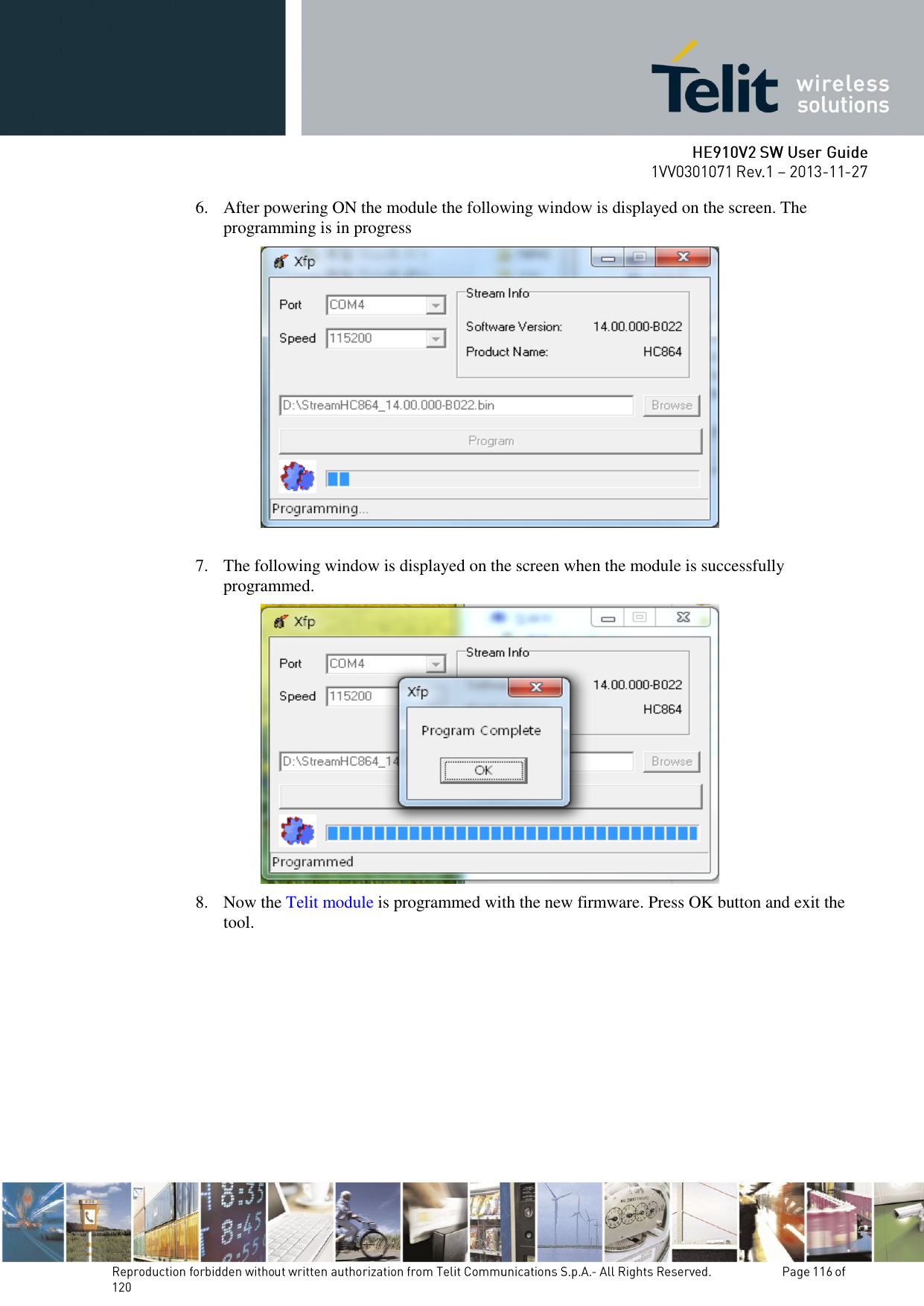
updated SW manual


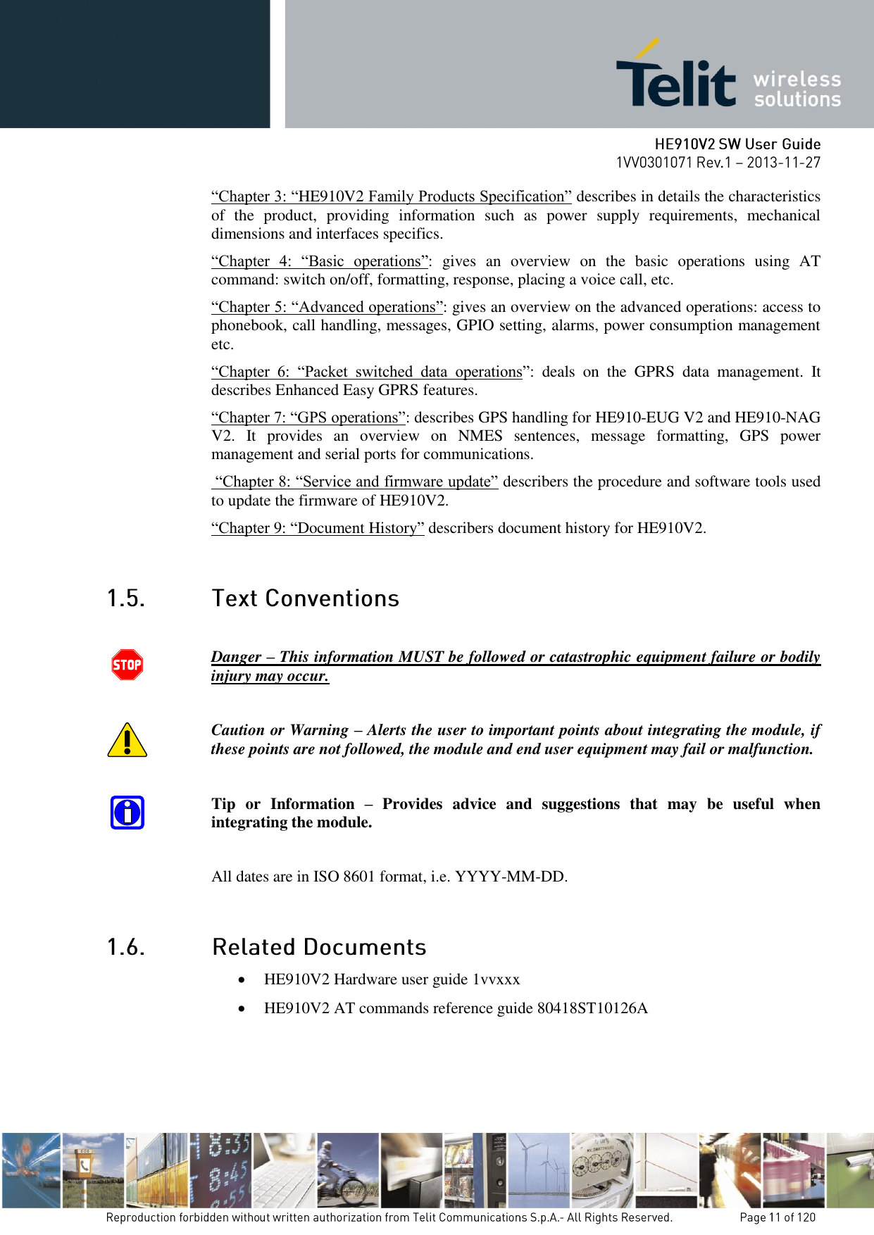
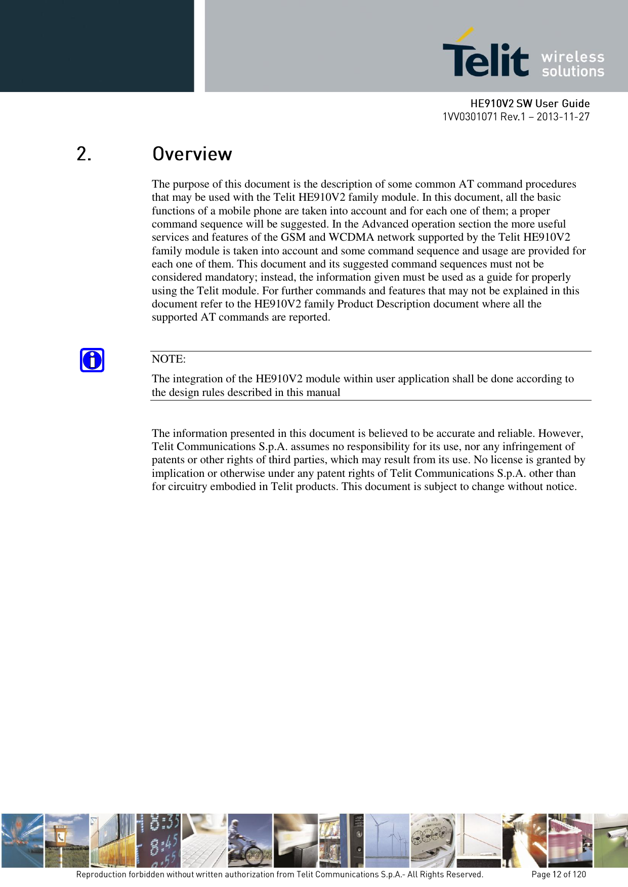

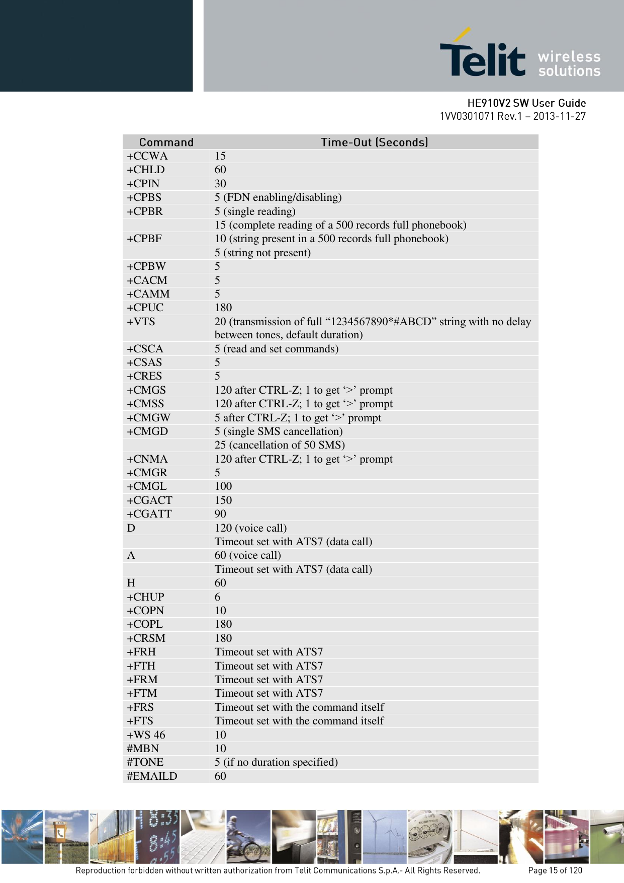
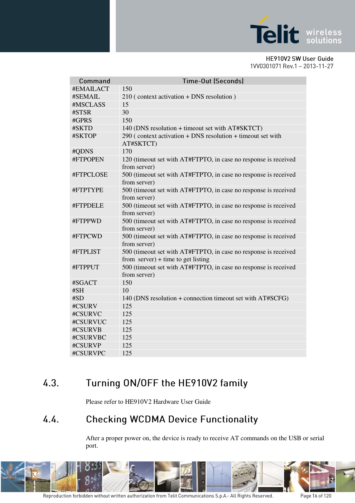
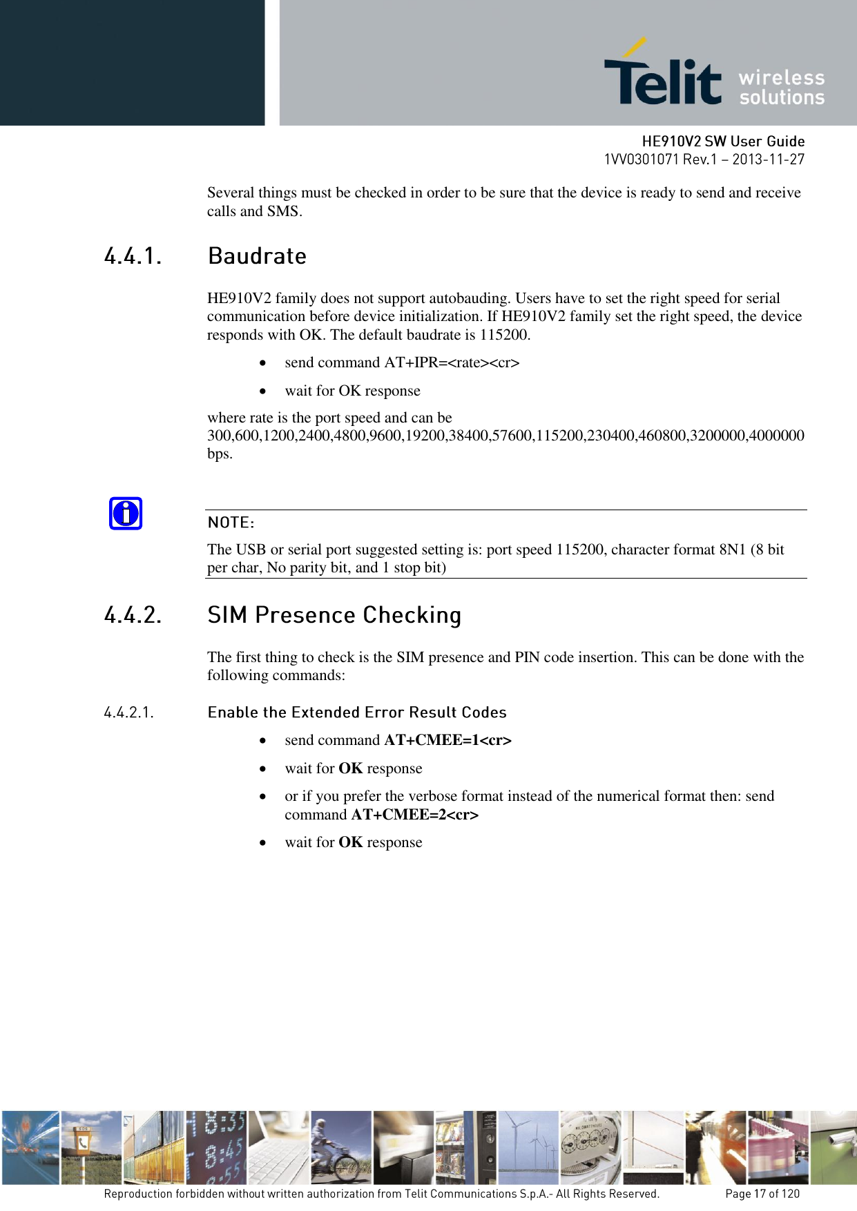
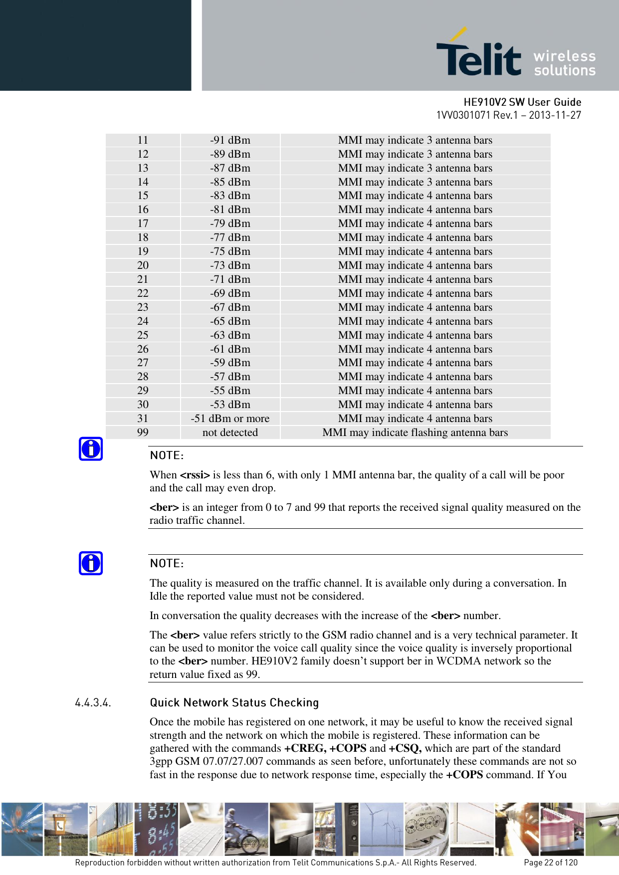
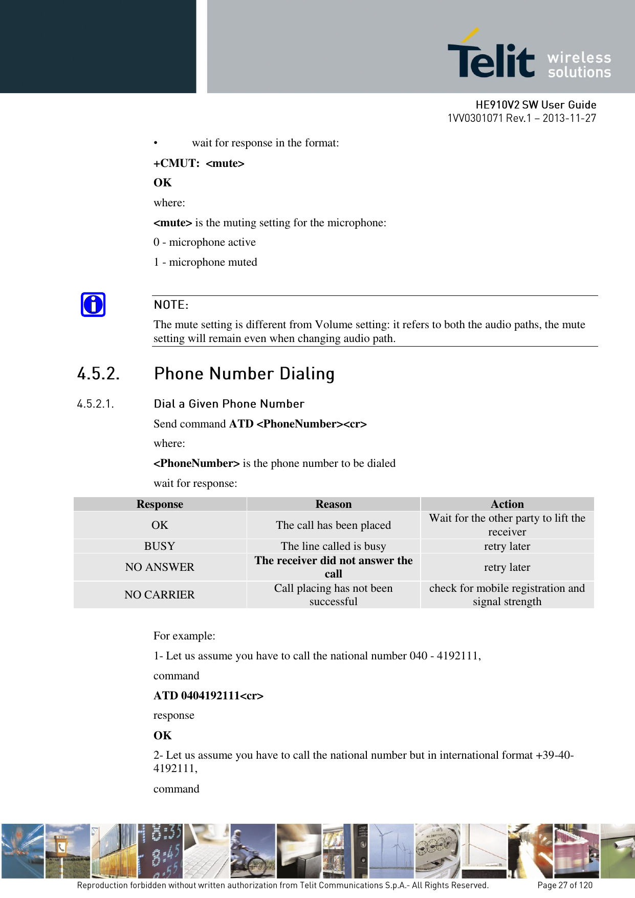
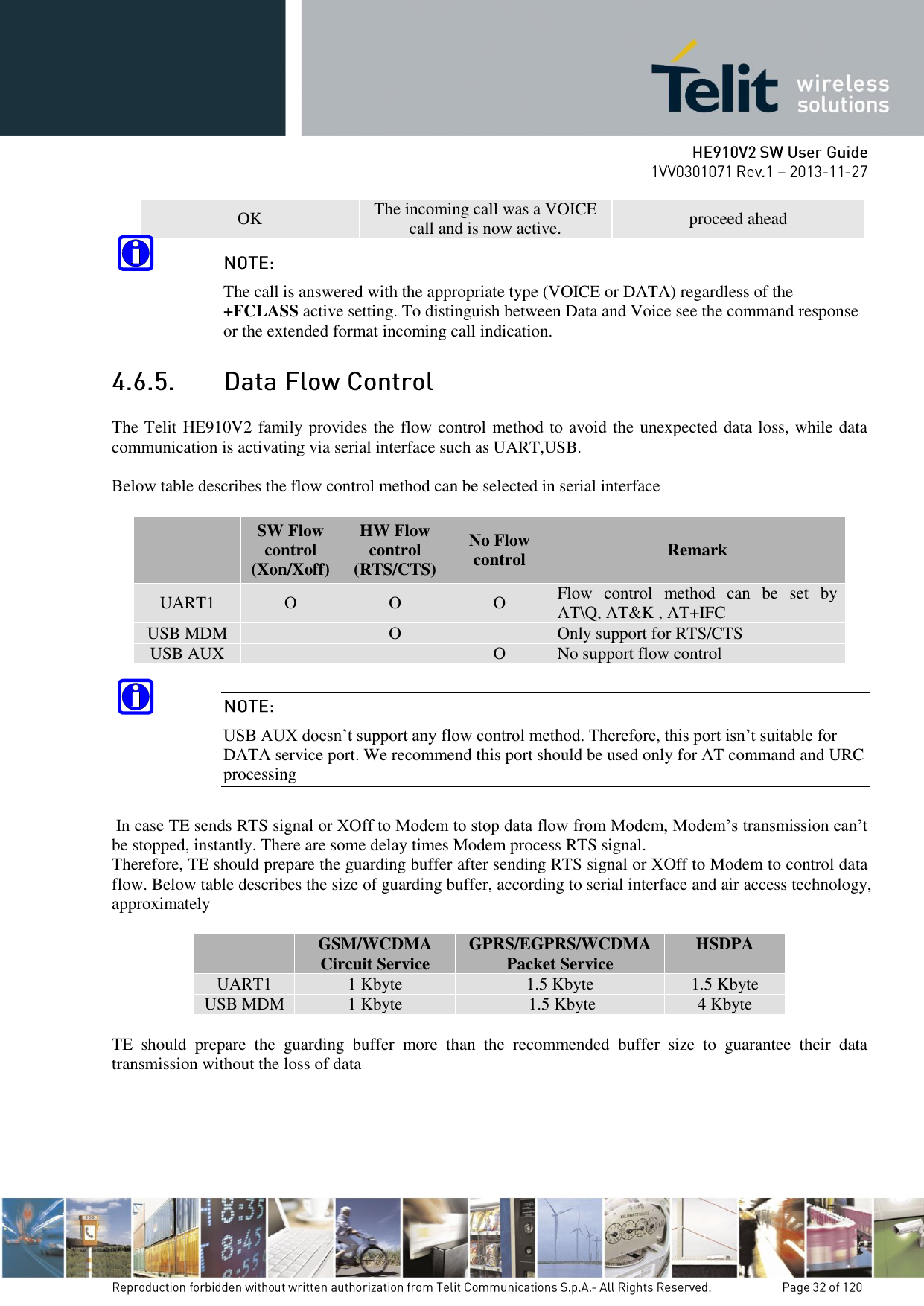
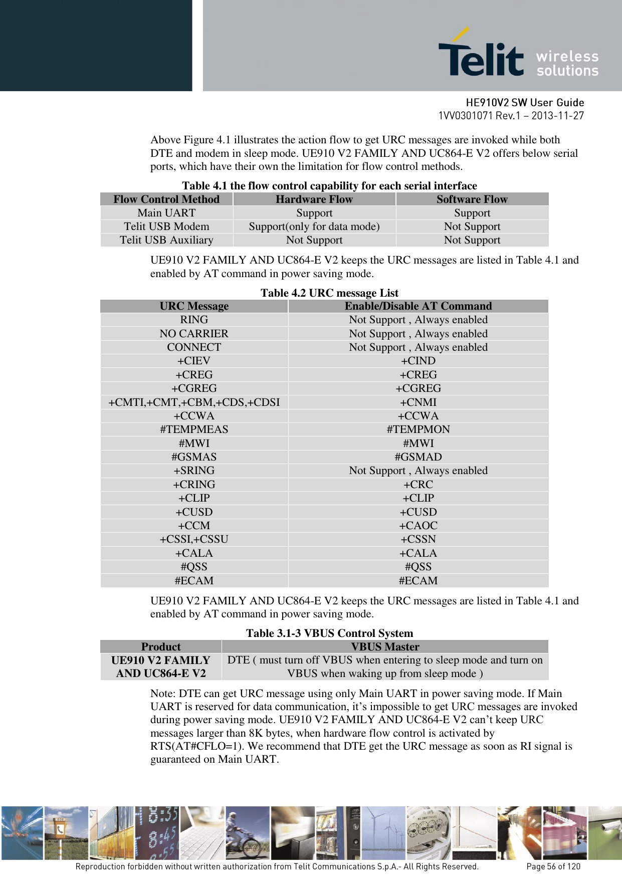
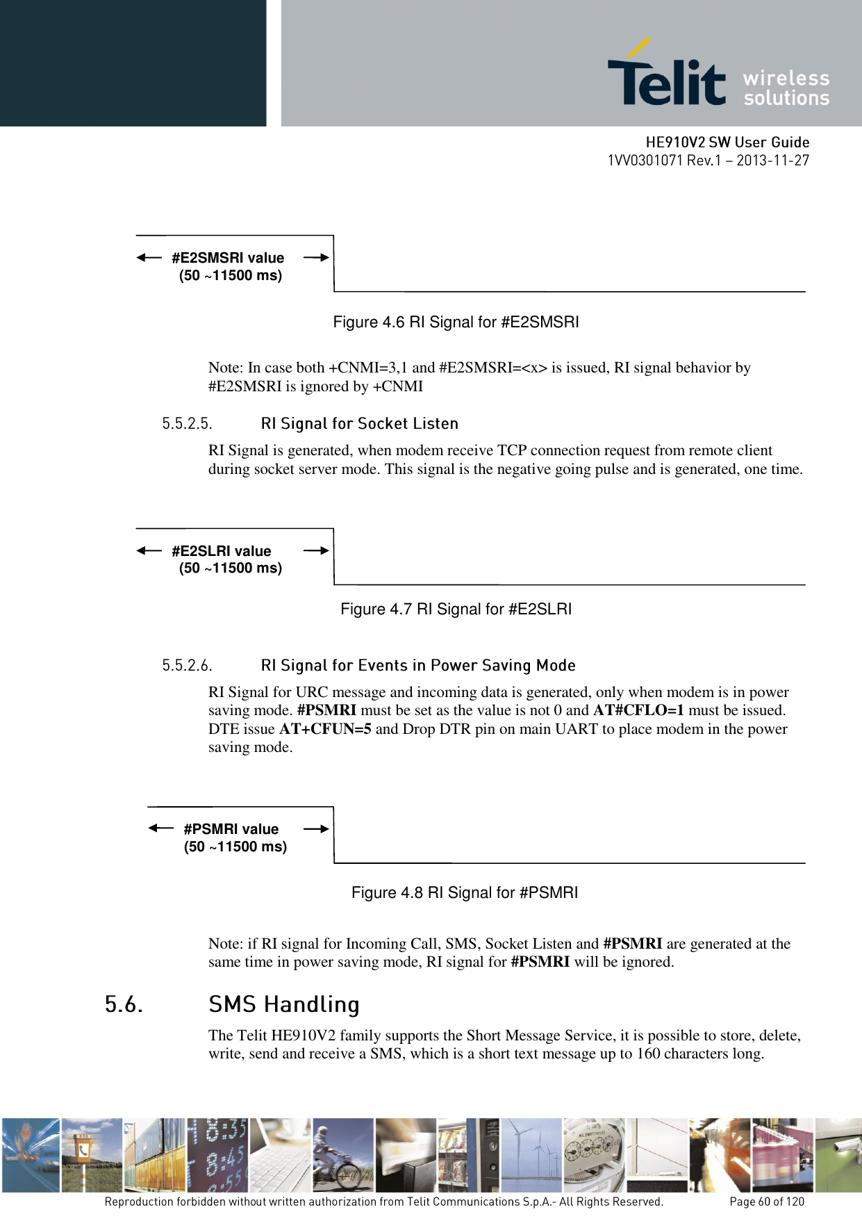
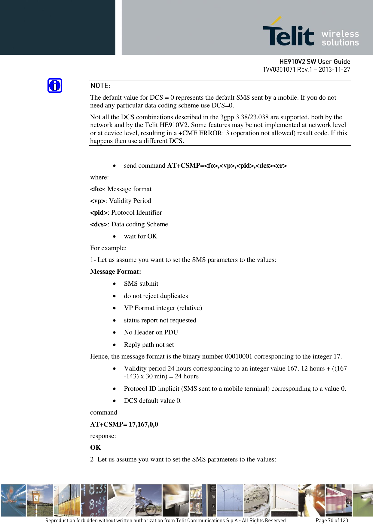
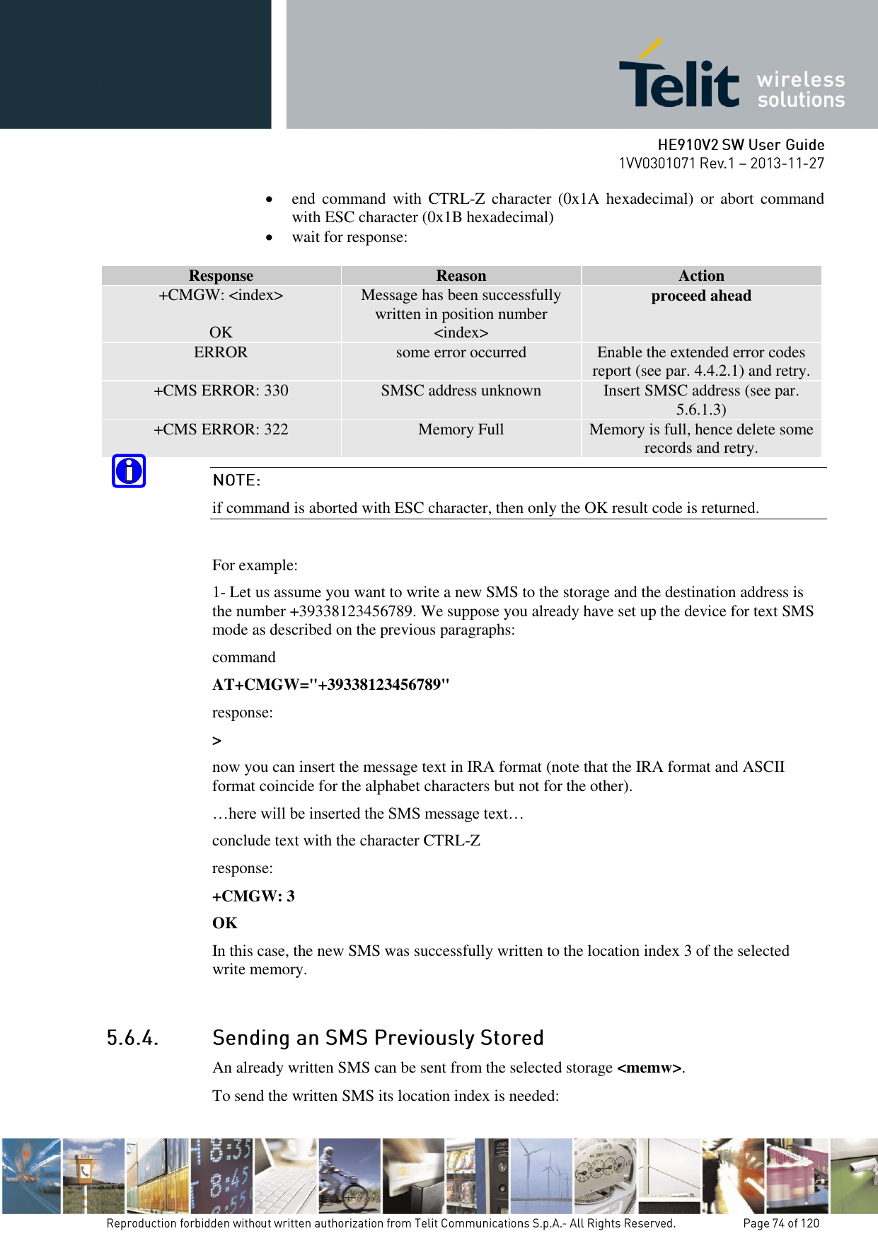
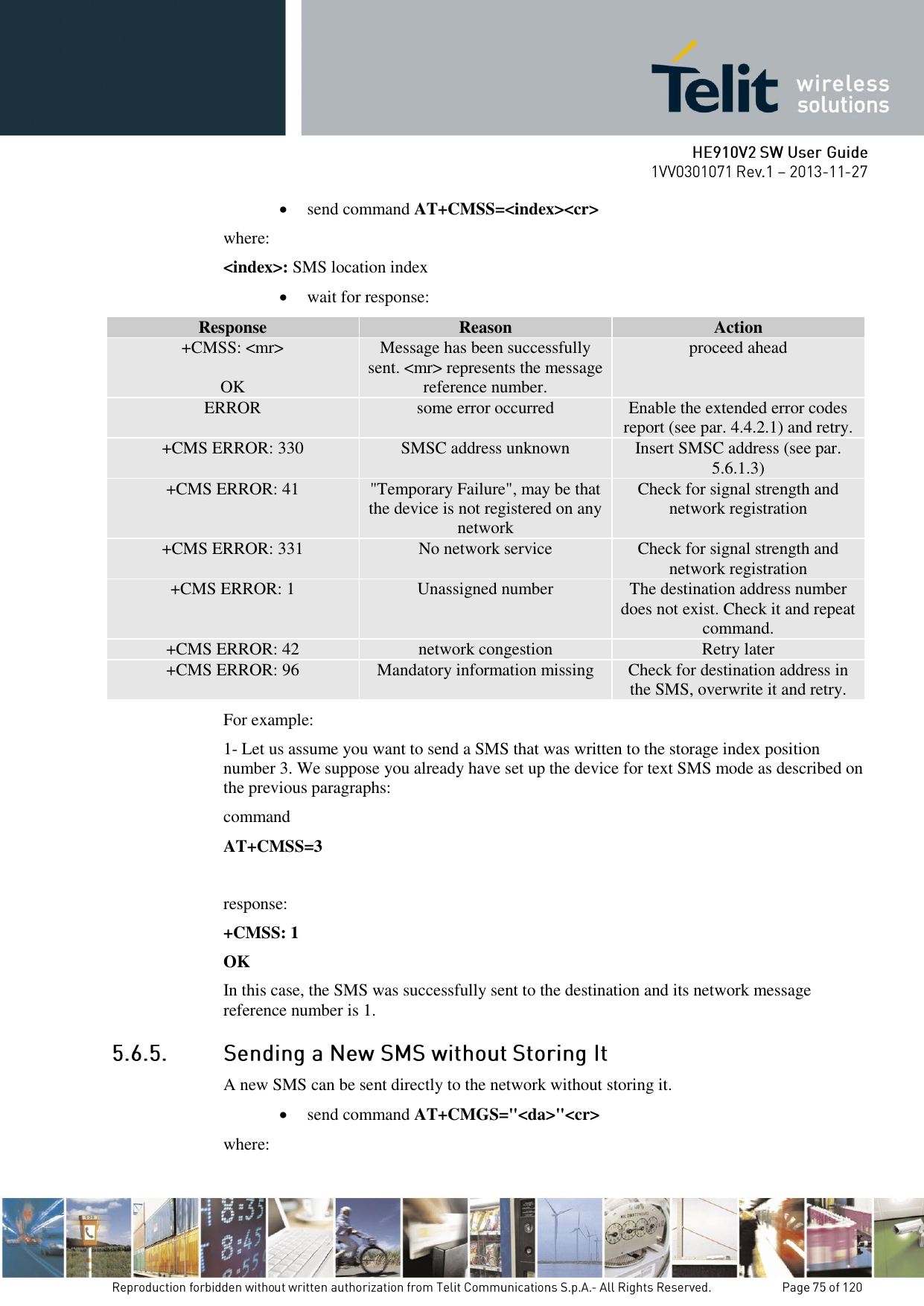
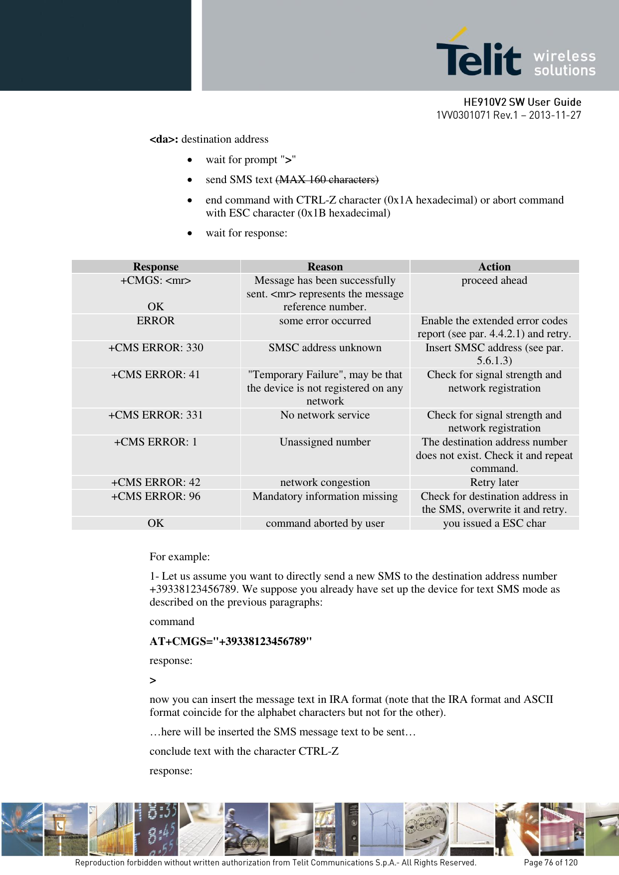
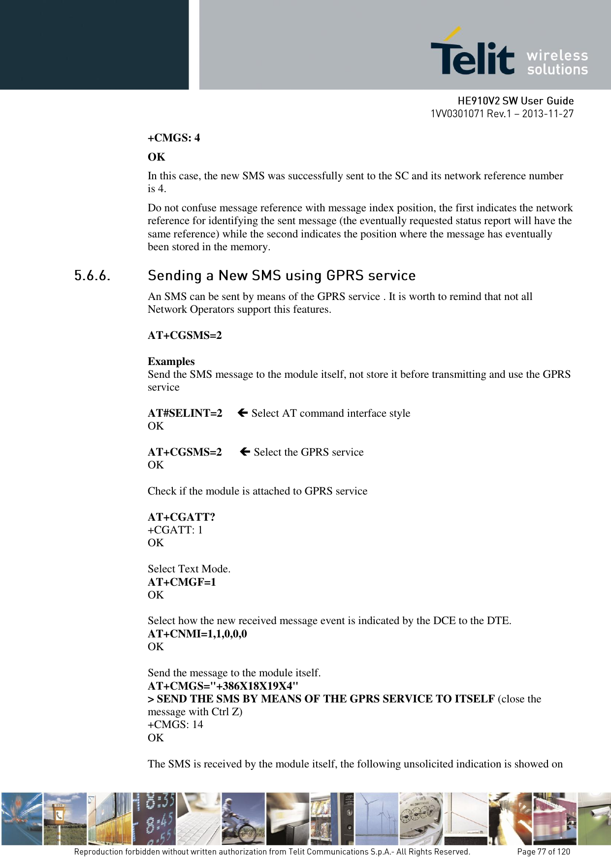
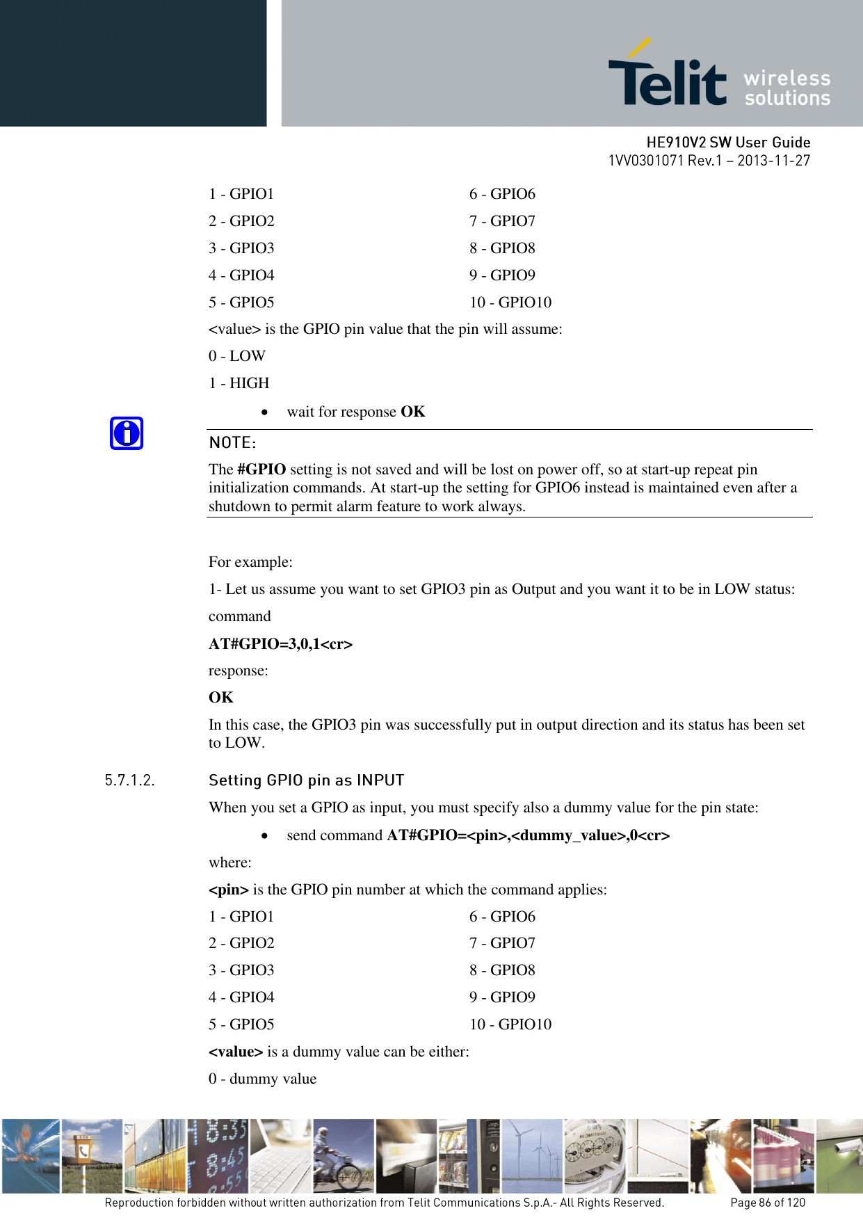
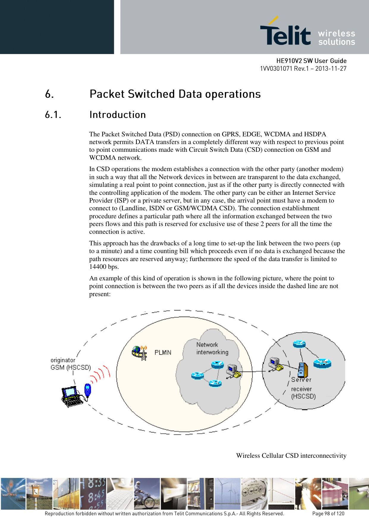
![In the next paragraphs the following notations are used: <cr> represents the Carriage Return Character (13) <lf> represents the Line Feed Character (10) <xx> represents a parameter with changing name is in place of the double x. (< and > characters are only for limiting the parameter and must not be issued to the terminal). [<xx>] represents an optional parameter whatever name is in place of the xx. [ and ] characters are only for limiting the optional parameter and must not be issued to the terminal). Every command issued to the Telit modules returns a result response if response codes are enabled (default). The time needed to process the given command and return the response varies, depending on the command type. Commands that do not interact with the SIM or the network, and involve only internal set up settings or readings, have an immediate response, depending on SIM configuration(e.g., number of contacts stored in the phonebook, number of stored SMS), or on the network the command may interact with. In the table below are listed only the commands whose interaction with the SIM or the network could lead to long response timings. When not otherwise specified, timing is referred to set command. For phonebook and SMS writing and reading related commands, timing is referred to commands issued after phonebook sorting is completed. For DTMF sending and dialing commands timing is referred to module registered on network (“AT+CREG?” answer is “+CREG: 0,1” or “+CREG: 0,5”). +COPS 125 (test command) +CLCK 15 (SS operation) 5 (FDN enabling/disabling) +CPWD 15 (SS operation) 5 (PIN modification) +CLIP 15 (read command) +CLIR 15 (read command) +CCFC 15 In case no response is received after the timeout time has been elapsed, then try repeating the last command and if still no response is received until the timeout time, an Unconditional Shutdown MUST be issued and the device must be powered ON again.](https://usermanual.wiki/Telit-Communications-S-p-A/HE910NAV2.updated-SW-manual/User-Guide-2159728-Page-14.png)
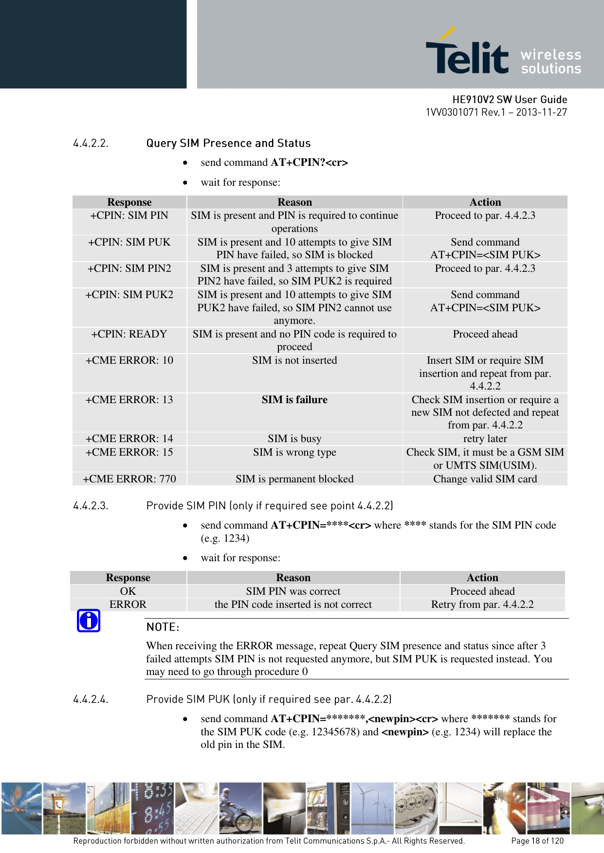
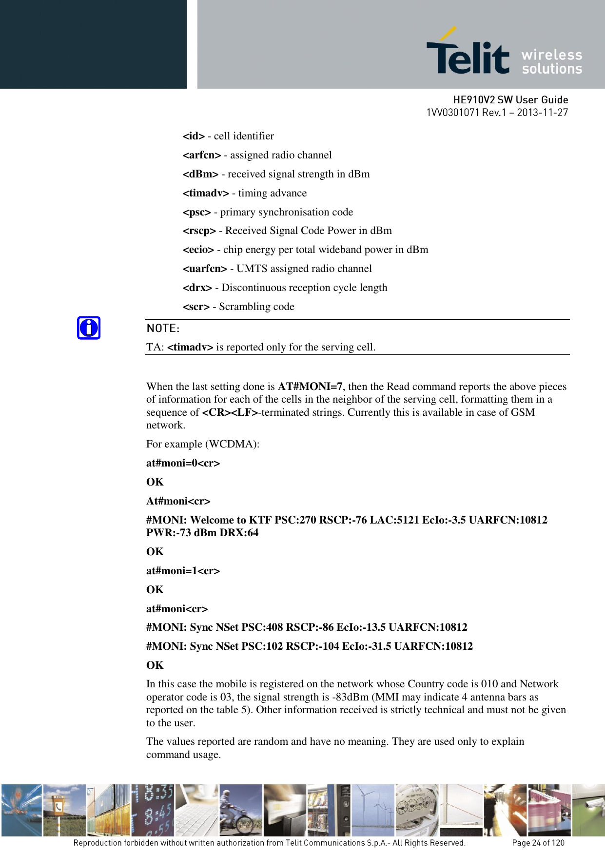
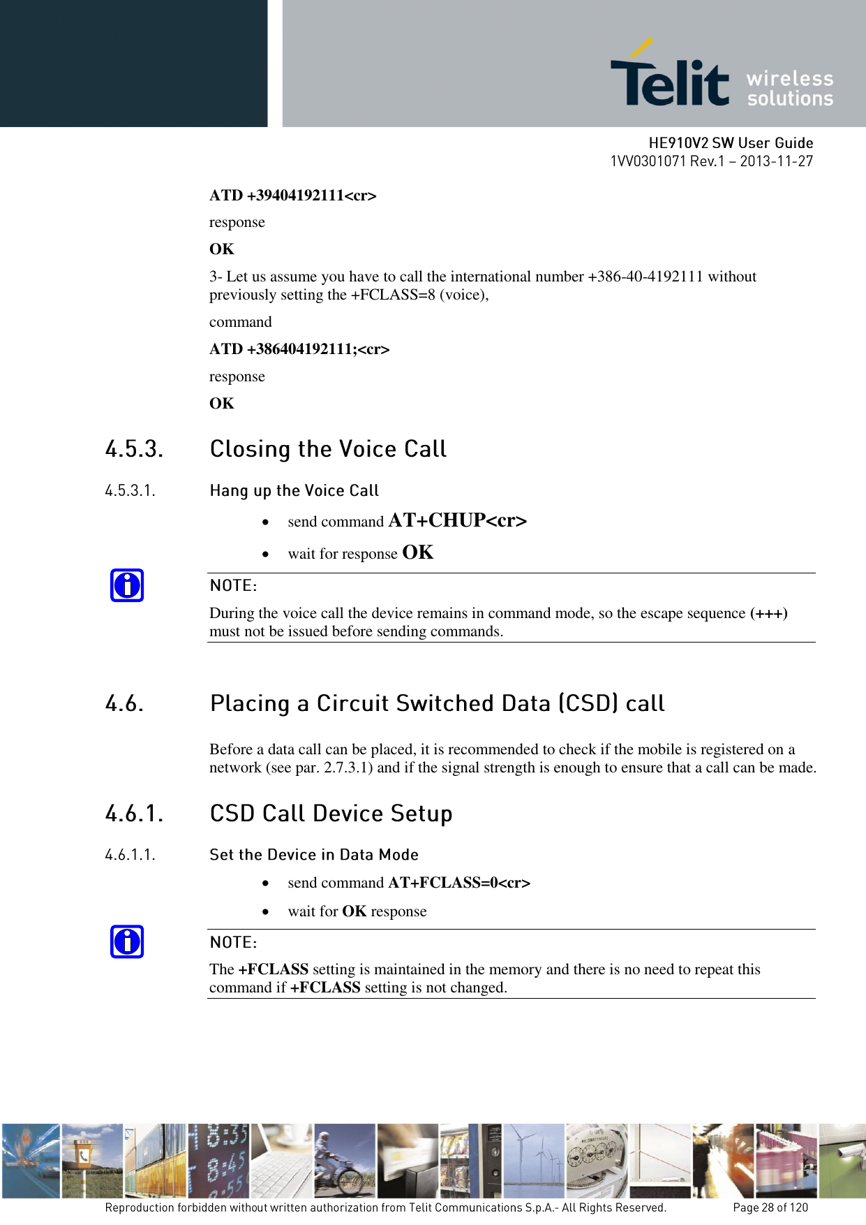
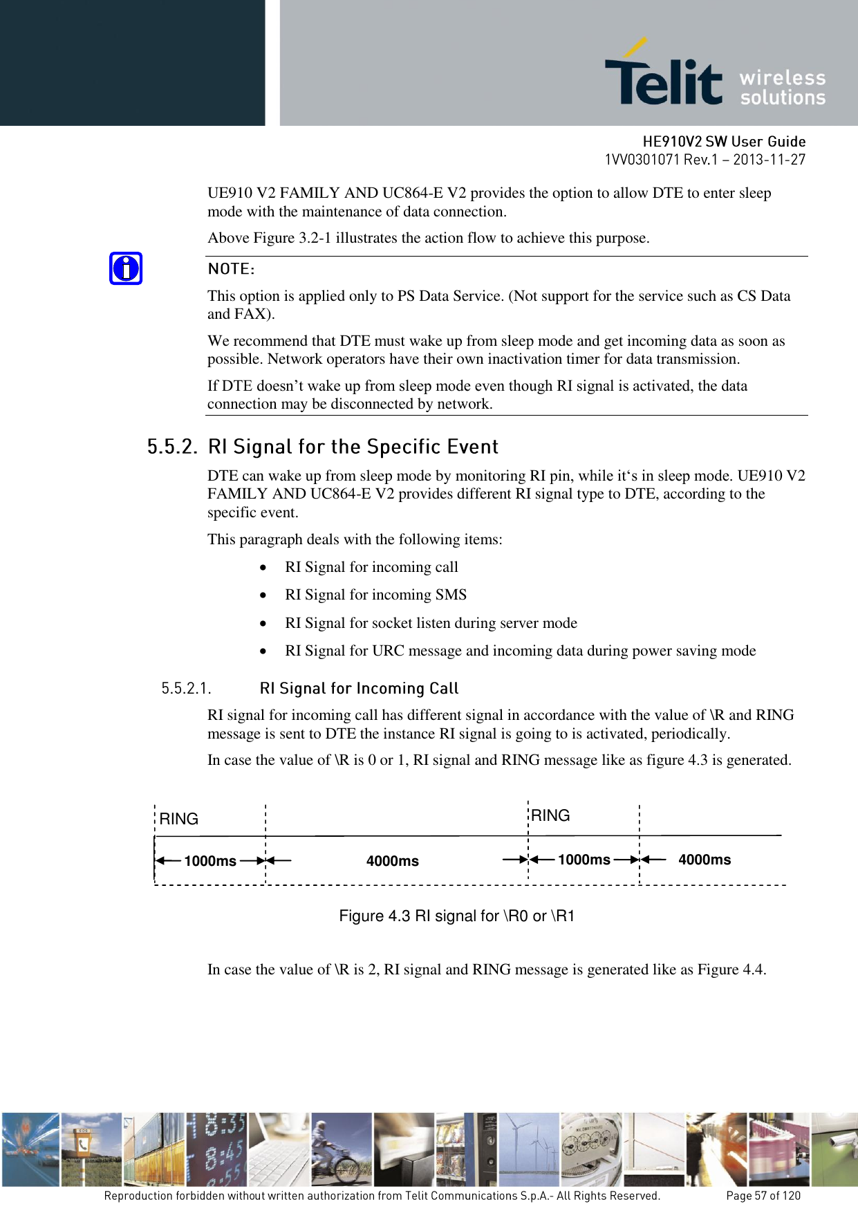
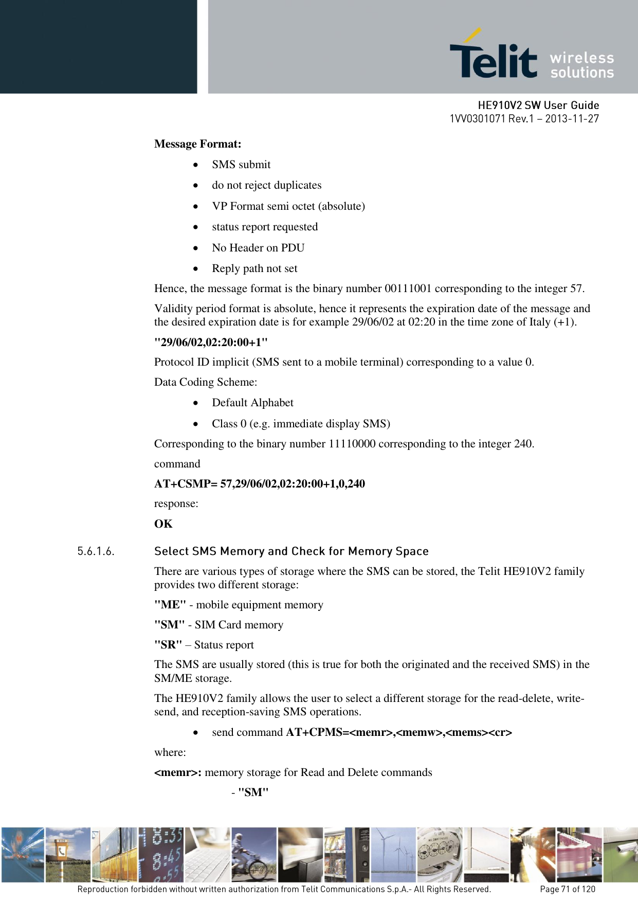
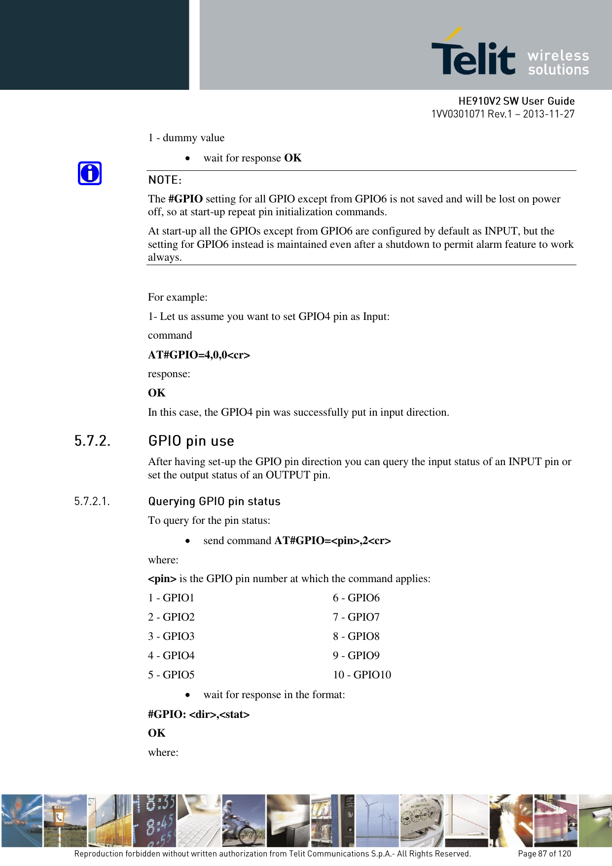
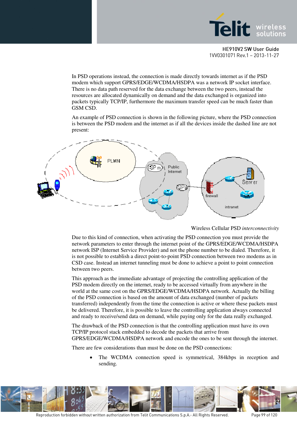
![When a response +CREG: x,1 or +CREG: x,5 is received, then the device is ready to place and receive a call or SMS. It is possible to jump directly to call setup procedures or SMS sending procedures. Once the mobile has registered on some network (or even if it has returned +CREG:x,3), it is possible to query the mobile for network identifications, codes and names: send command AT+COPS=?<cr> wait for response in the format: +COPS: : [list of supported (<stat>,long alphanumeric <oper>,short alphanumeric <oper>,numeric <oper>,< AcT>)s] [,,(list of supported <mode>s),(list of supported <format>s)] where: <stat> - operator availability 0 - unknown 1 - available 2 - current 3 - forbidden <AcT> access technology selected: 0 GSM 2 UTRAN Since with this command a network scan is done, this command may require some seconds before the output is given.For example: command AT+COPS=?<cr> Answer: +COPS: (2,"I WIND","WIND","22288",2),(1,"SI MOBITEL GSM","","29341",0),(1,"Vodafone IT","OMNITEL","22210",2), (3,"I TIM","TIM","22201",0),,(0-4),(0-2) OK In this case the mobile is registered on the network "I WIND" which is a network from Italy, code: 222 and Network ID: 88. There is also another network available for registration: "SI MOBITEL GSM" which is a network from Slovenia, code: 293 and Network ID: 41 ,](https://usermanual.wiki/Telit-Communications-S-p-A/HE910NAV2.updated-SW-manual/User-Guide-2159728-Page-20.png)
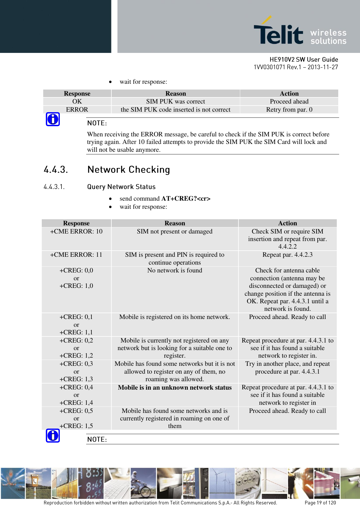
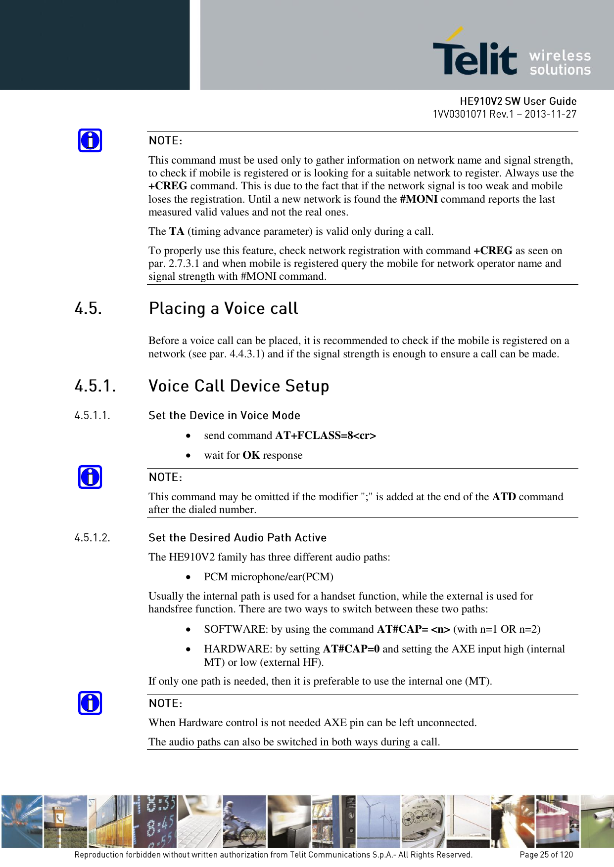
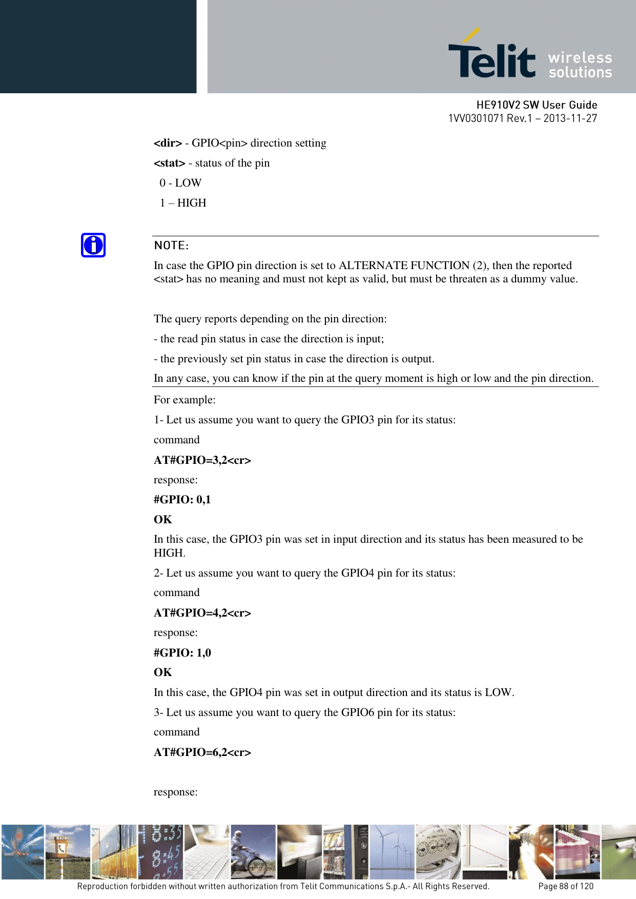
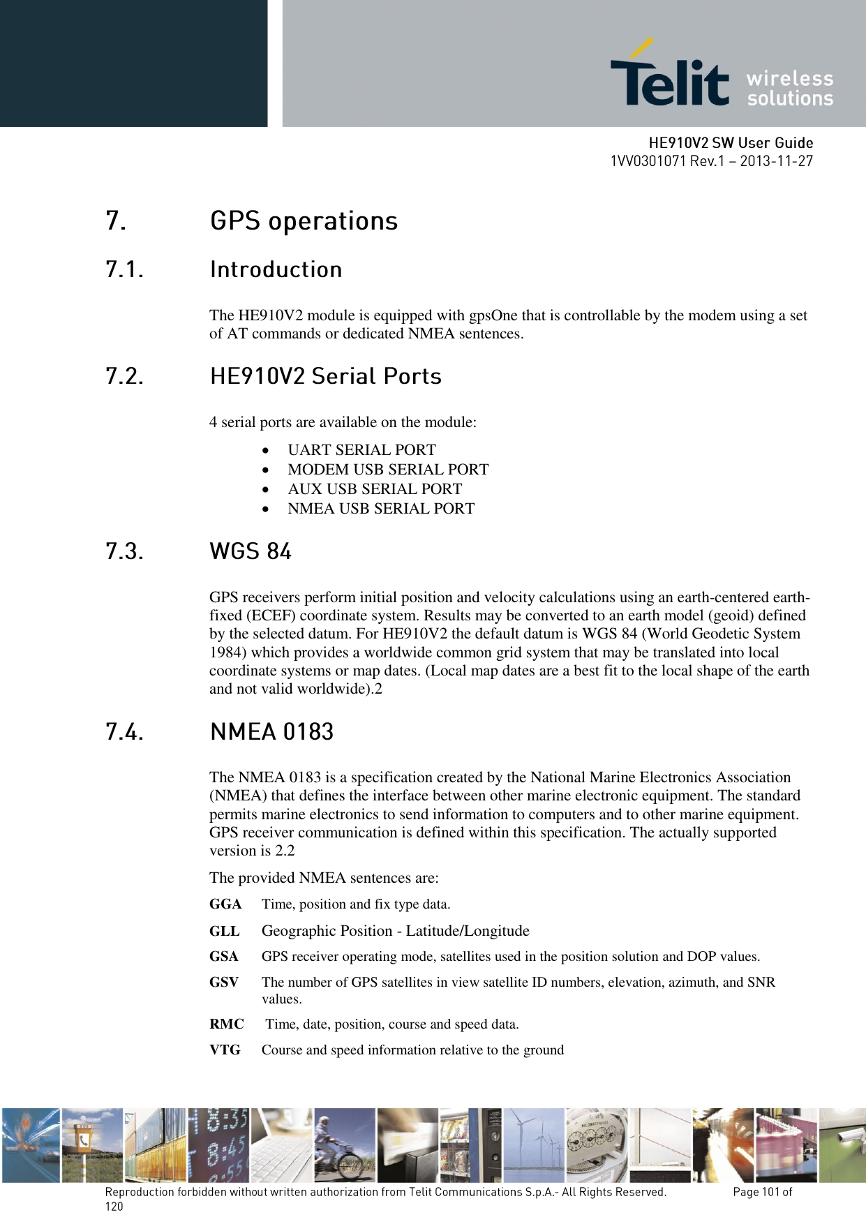
![want to keep your software as general as possible you can follow the indications given before and forget this part; instead if you need or want a faster way to check at the mobile network information, the HE910V2 family provides a special command #MONI which can be used to gather all the information needed in a faster and simpler way: send command AT#MONI=0<cr> wait for OK response send command AT#MONI?<cr> wait for response in the format: When extracting data for the serving cell and the network name is known the format is: (GSM network) #MONI: <netname> BSIC:<bsic> RxQual:<qual> LAC:<lac> Id:<id> ARFCN:<arfcn> PWR:<dBm> dBm TA: <timadv> (WCDMA network) #MONI: <netmame> PSC:<psc> RSCP:<rscp> LAC:<lac> Id:<id> EcIo:<ecio> UARFCN:<uarfcn> PWR:<dBm> dBm DRX:<drx> SCR:<scr> When the network name is unknown, the format is: (GSM network) #MONI: Cc:<cc> Nc:<nc> BSIC:<bsic> RxQual:<qual> LAC:<lac> Id:<id> ARFCN:<arfcn> PWR:<dBm> dBm TA: <timadv> (WCDMA network) #MONI: Cc:<cc> Nc:<nc> PSC:<psc> RSCP:<rscp> LAC:,<lac> Id:<id> EcIo:<ecio> UARFCN:<uarfcn> PWR:<dBm> dBm DRX:<drx> SCR:<scr> When extracting data for an adjacent cell, the format is: (GSM network) #MONI: Adj Cell<n> [LAC:<lac> Id:<id>] ARFCN:<arfcn> PWR:<dBm> dBm (WCDMA network) #MONI: PSC:<psc> RSCP:<rscp> EcIo:<ecio> UARFCN:<uarfcn> SCR:<scr> Where: <netname> - name of network operator <cc> - country code <nc> - network operator code <n> - progressive number of adjacent cell <bsic> - base station identification code <qual> - quality of reception 0..7 <lac> - localization area code](https://usermanual.wiki/Telit-Communications-S-p-A/HE910NAV2.updated-SW-manual/User-Guide-2159728-Page-23.png)
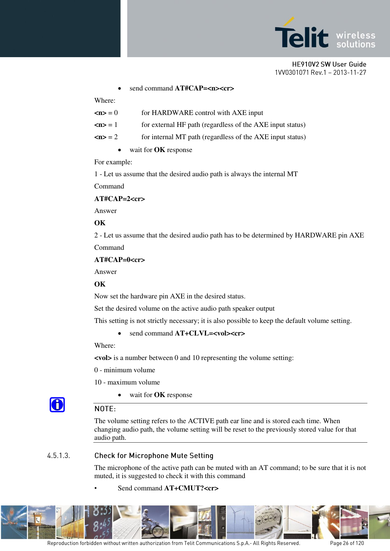
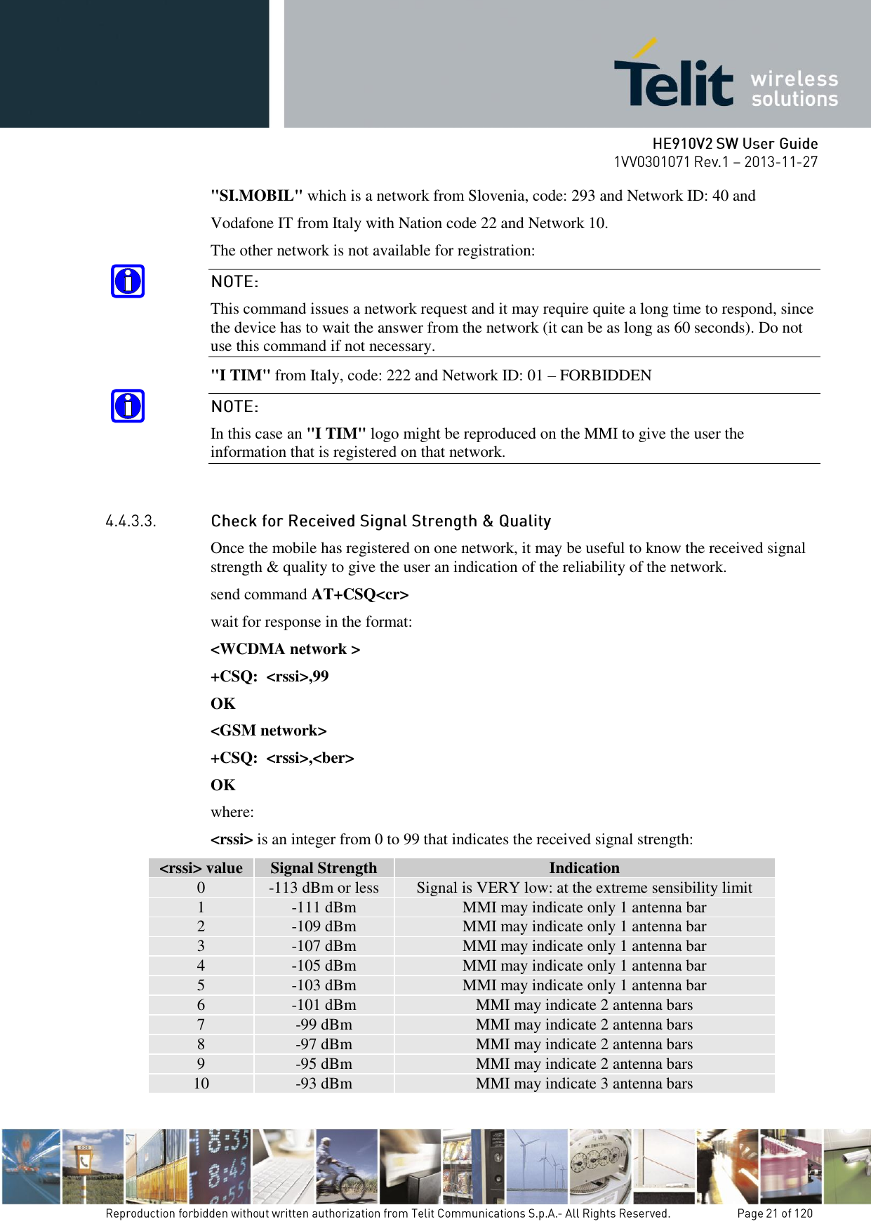
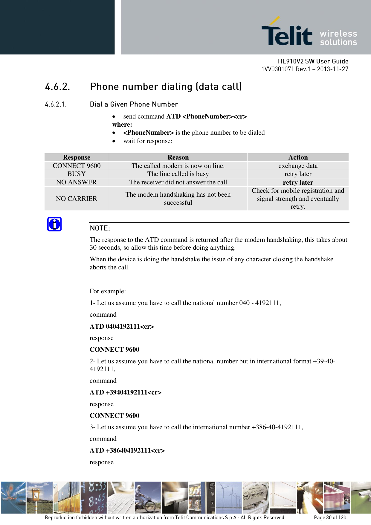
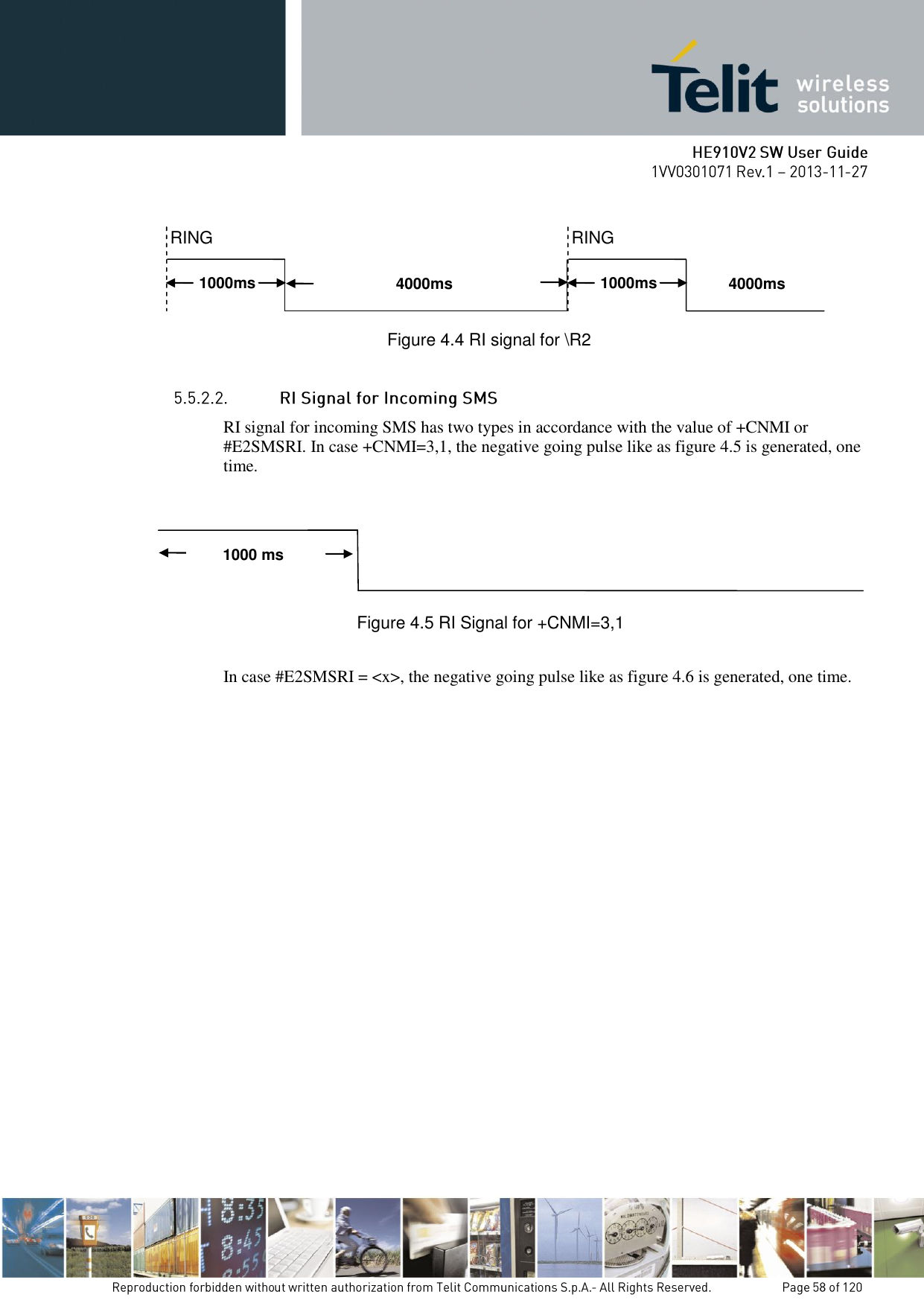
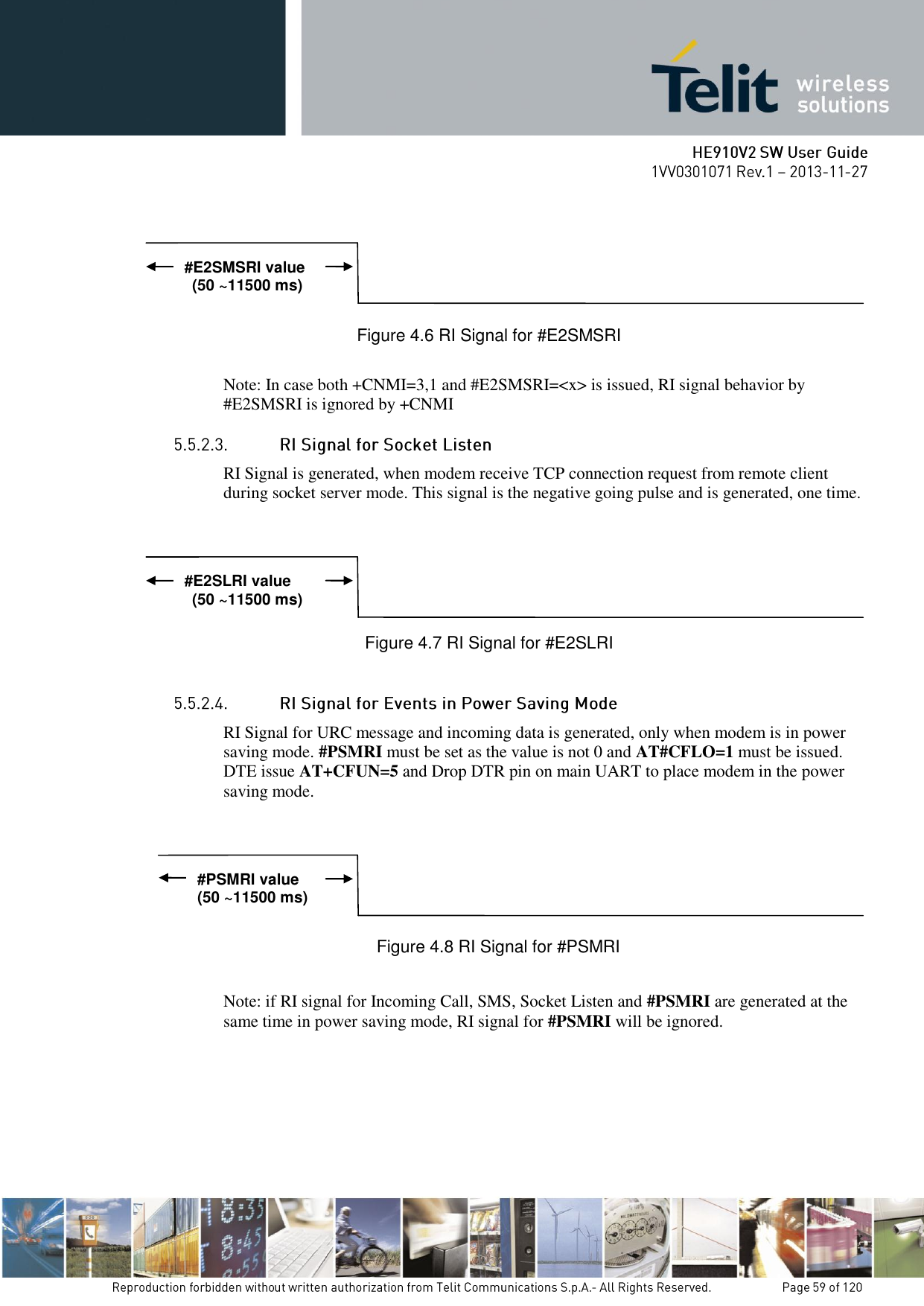
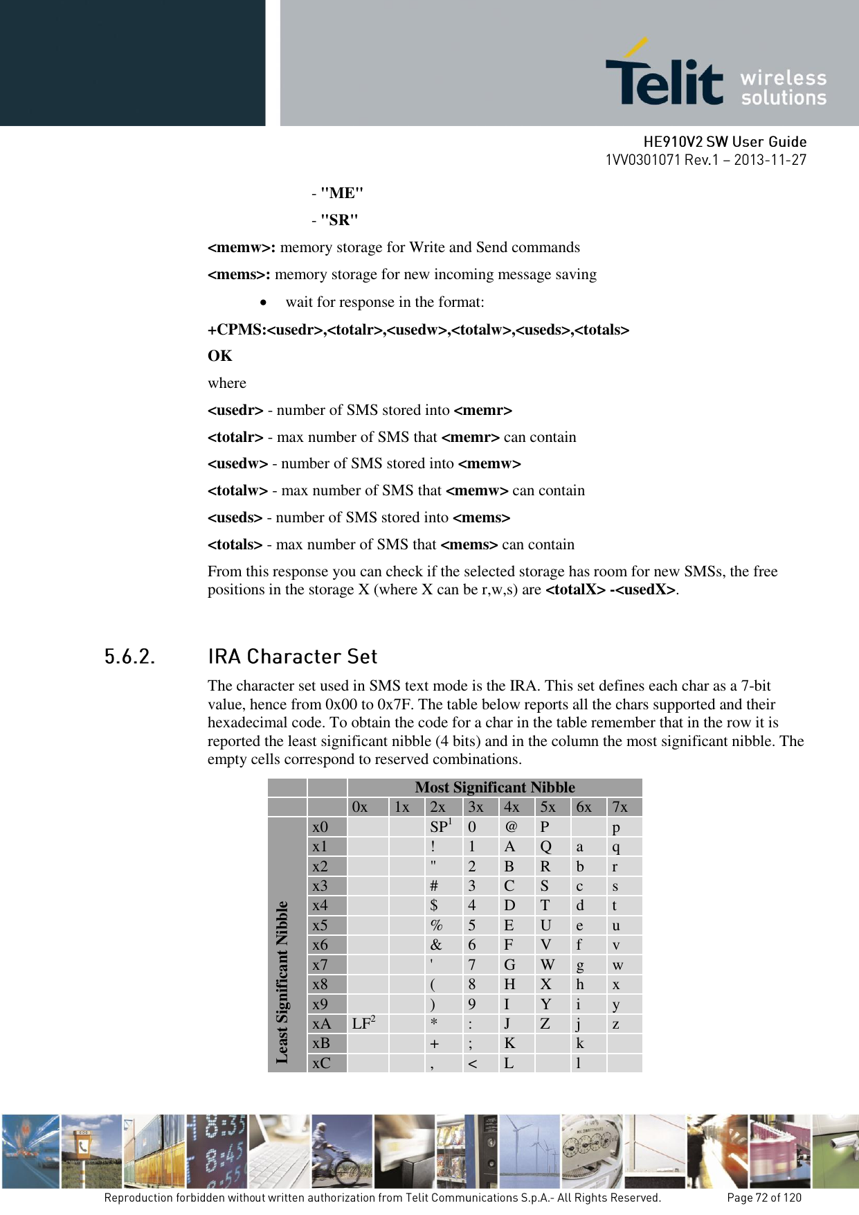
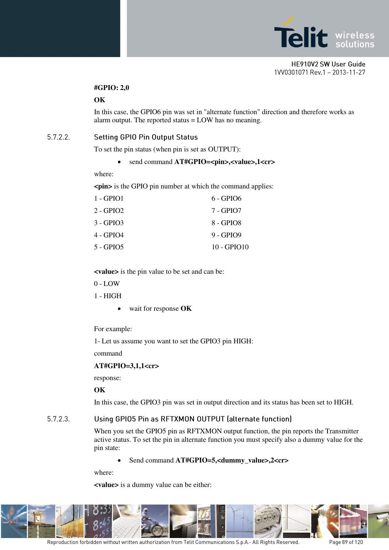
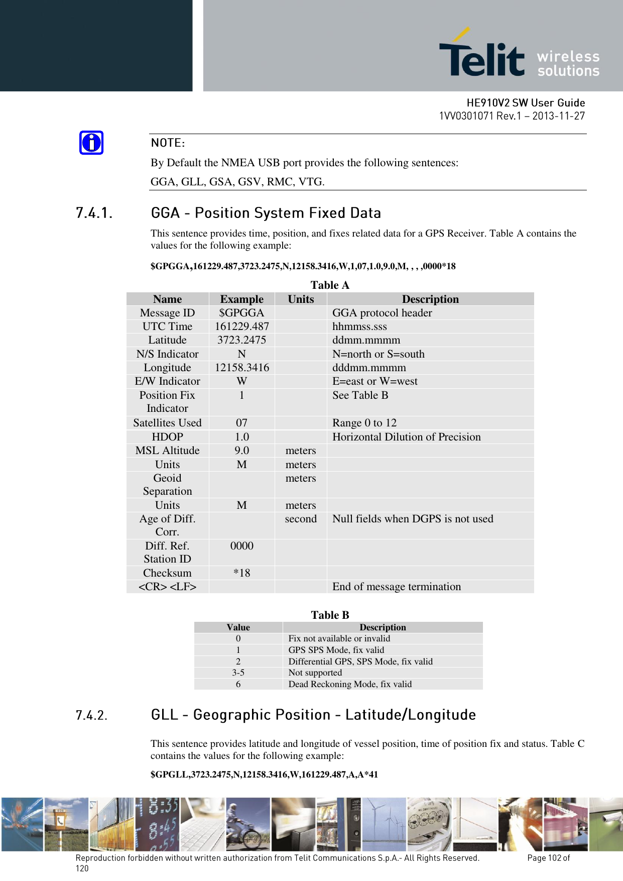
![The data connection can be made using different modulations at different speeds. This connection mode can be selected with the command +CBST. The syntax for the command is: AT+CBST=<mod>,0,<ce> These parameters can be selected as seen in the table: <WCDMA network> Command Modulation Speed [bps] Connection Element AT+CBST=0,0,1 V.32 9600 non transparent AT+CBST=14,0,1 V.34 14400 non transparent AT+CBST=16,0,1 V.34 28800 non transparent AT+CBST=17,0,1 V.34 33600 non transparent AT+CBST=43,0,1 V.120 14400 non transparent AT+CBST=48,0,1 V.120 28800 non transparent AT+CBST=51,0,1 V.120 56000 non transparent AT+CBST=75,0,1 V.110/ X.31 14400 non transparent AT+CBST=80,0,1 V.110 / X.31 28800 non transparent AT+CBST=81,0,1 V.110 / X.31 38400 non transparent AT+CBST=83,0,1 V.110/ X.31 56000 non transparent AT+CBST=83,4,1 V.110/ X.31 56000 RDI non transparent AT+CBST=84,0,1 X.31 64000 non transparent AT+CBST=116,1,0 Bit transparent 64000 transparent AT+CBST=134,1,0 multimedia 64000 transparent <GSM network> Command Modulation Speed [bps] Connection Element AT+CBST=0,0,1 V.32 9600 non transparent AT+CBST=7,0,1 V.32 9600 non transparent AT+CBST=12,0,1 V.34 9600 non transparent AT+CBST=14,0,1 V.34 14400 non transparent AT+CBST=39,0,1 V.120 9600 non transparent AT+CBST=43,0,1 V.120 14400 non transparent AT+CBST=71,0,1 V110/ X.31 9600 non transparent AT+CBST=75,0,1 V.110/ X.31 14400 non transparent AT+CBST=7,0,0 V.32 9600 transparent AT+CBST=12,0,0 V.34 9600 transparent AT+CBST=14,0,0 V.34 14400 transparent Once selected the appropriate <mod > and <ce> parameters from the table: send command AT+CBST=<mod>,0,<ce><cr> wait for OK response](https://usermanual.wiki/Telit-Communications-S-p-A/HE910NAV2.updated-SW-manual/User-Guide-2159728-Page-29.png)
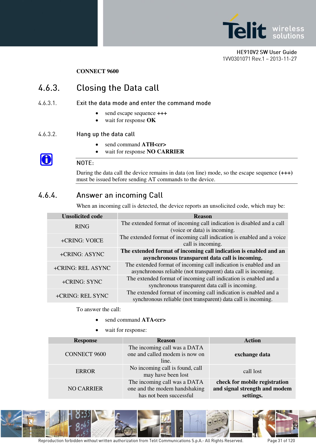
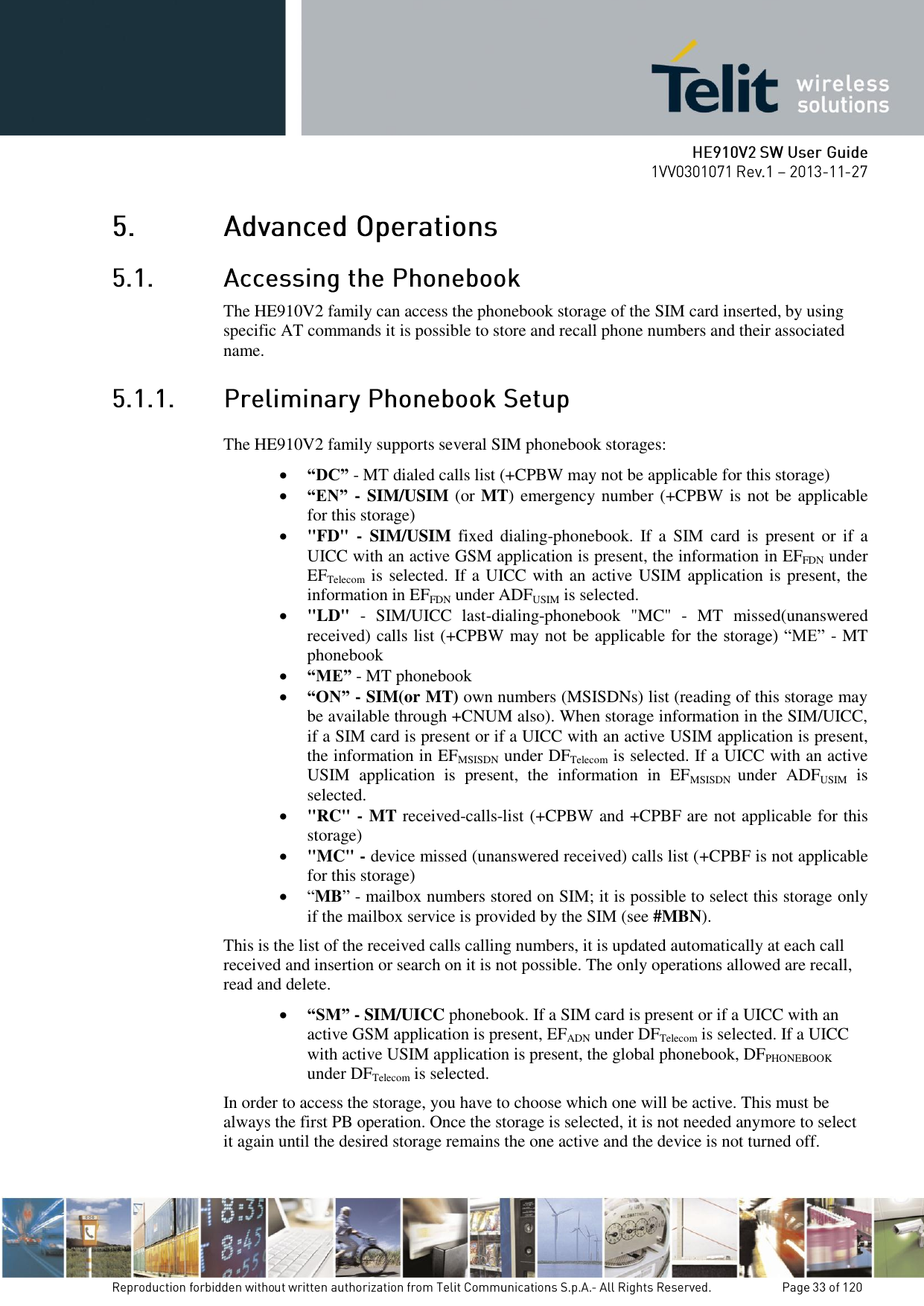
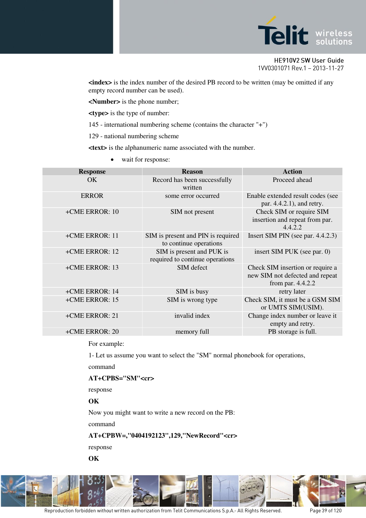
![ send command AT+CPBS=<storage>[<,passwrod>]<cr> where: <storage> is the desired PB storage: “DC” - MT dialed calls list (+CPBW may not be applicable for this storage) “EN” - SIM/USIM (or MT) emergency number (+CPBW is not be applicable for this storage) “FD” - SIM/USIM fixed dialing phonebook “LD” - SIM/USIM last dialing phonebook “MC” - missed calls list “MB” - mailbox numbers stored on SIM “ME” - MT phonebook “ON” - SIM (or MT) own numbers (MSI storage may be available through +CNUM also). “RC” - received calls list “SM” - SIM/USIM phonebook <password>: string type value representing the PIN2-code required when selecting PIN2-code locked <storage>s above, e.g. "FD" or the hidden key to be verified in order to access to the hidden phonebook entries in the SIM/USIM or any other phonebook with hidden entries. wait for response: Response Reason Action OK selected PB is now active Proceed ahead ERROR some error occurred Enable extended result codes (see par. 4.4.2.1) and retry. +CME ERROR: 10 SIM not present Check SIM or require SIM insertion and repeat from par. 4.4.2.2 +CME ERROR: 11 SIM is present and PIN is required to continue operations Insert SIM PIN (see par. 4.4.2.3) +CME ERROR: 12 SIM is present and PUK is required to continue operations insert SIM PUK (see par. 0) +CME ERROR: 13 SIM defect Check SIM insertion or require a new SIM not defected and repeat from par. 4.4.2.2 +CME ERROR: 14 SIM is busy retry later +CME ERROR: 15 SIM is wrong type Check SIM, it must be a GSM SIM or UMTS SIM(USIM). +CME ERROR: 17 PIN2 is required to continue Enable FD facility with +CLCK](https://usermanual.wiki/Telit-Communications-S-p-A/HE910NAV2.updated-SW-manual/User-Guide-2159728-Page-34.png)
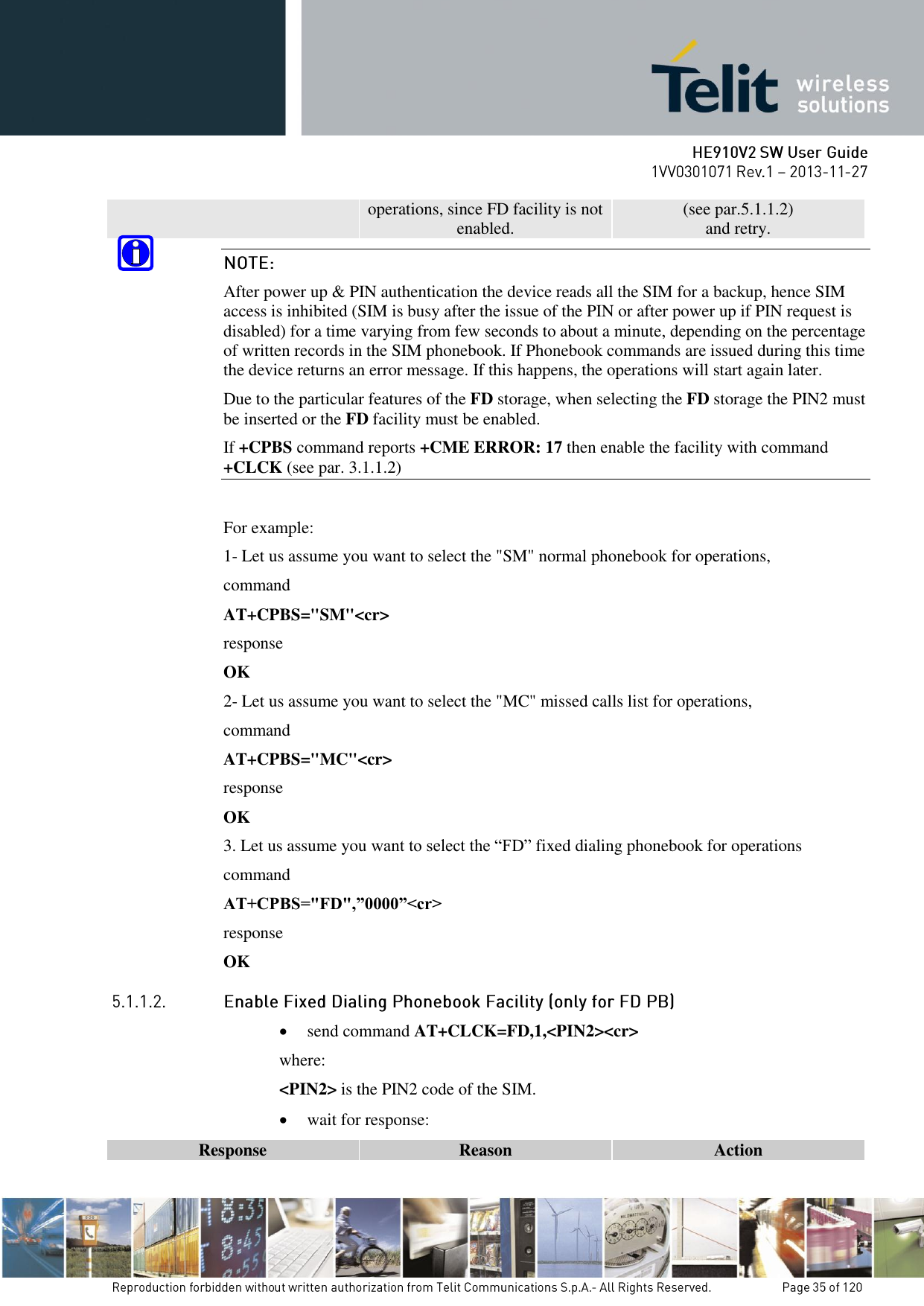
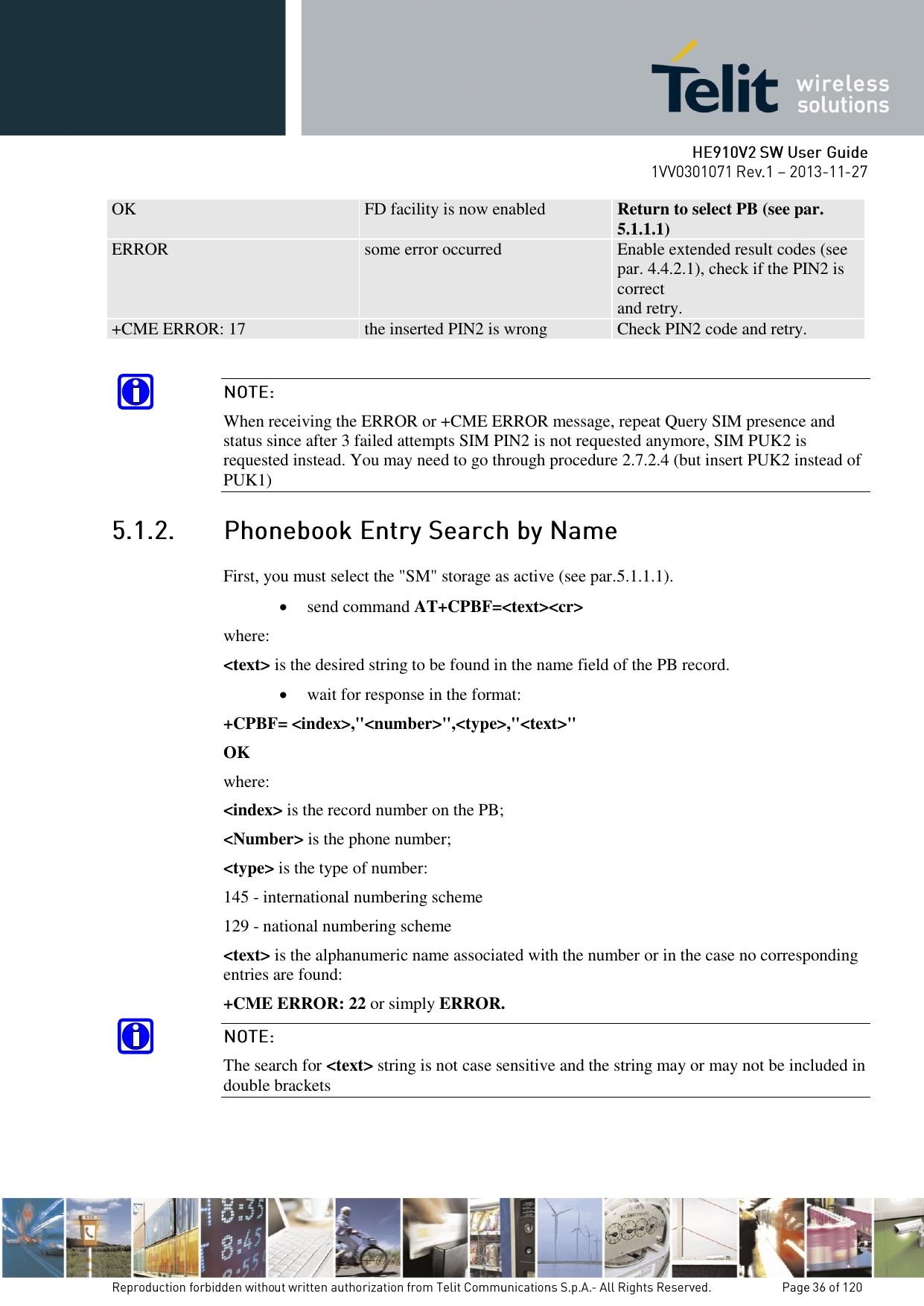
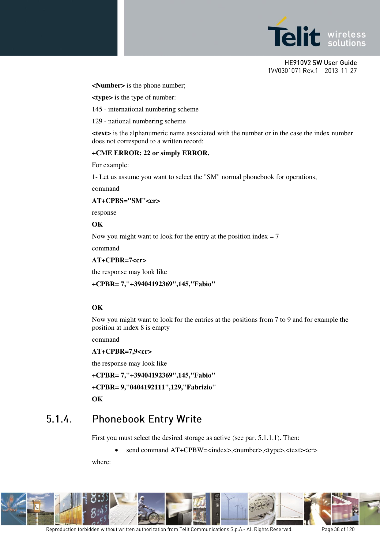
![For example: 1- Let us assume you want to select the "SM" normal phonebook for operations, command AT+CPBS="SM"<cr> response OK Now you might want to look for the entries with the name starting with: "FA" command AT+CPBF="FA"<cr> the response may look like: +CPBF= 7,"+39404192369",145,"Fabio" +CPBF= 9,"0404192111",129,"Fabrizio" OK Now you might want to look for the entries with the name starting with: "FAUSTO" but no record contains this name: command AT+CPBF="FAUSTO"<cr> response +CME ERROR: 22 or if extended error codes are disabled simply response ERROR First, you must select the desired storage as active (see par. 5.1.1.1). Then: send command AT+CPBR=<index>[,<index2>]<cr> where: <index> is the index number of the desired PB record to be read. wait for response in the format: +CPBR= <index>,"<number>",<type>,"<text>" OK where: <index> is the record number on the PB;](https://usermanual.wiki/Telit-Communications-S-p-A/HE910NAV2.updated-SW-manual/User-Guide-2159728-Page-37.png)
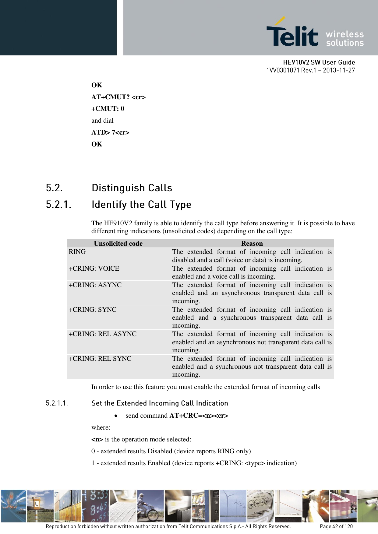
![ wait for OK response The HE910V2 family is able to identify the caller number and give indication of it before the call is answered. The calling number is presented after each RING or +CRING indication in the format: +CLIP: "<number>",<type>[,"<subaddress>",<satype>[,"<alpha>"[,<CLI validity>]]] OK where: <Number> is the phone number; <type> is the type of number: 145 - international numbering scheme 129 - national numbering scheme <subaddress> is the subaddress of the calling party <satype> is the type of subaddress <alpha> is an optional string type alphanumeric representation of <number> corresponding to the entry found in phonebook; <CLI validity> is the validity status of CLI presentation: 0 CLI valid. 1 CLI has been withheld by the originator. 2 CLI is not available due to interworking problems or limitation or originating network. In order to use this feature you must enable the caller ID indication presentation, if feature is disabled then no CLI indication is given after the RING or +CRING code. send command AT+CLIP=<n><cr> where: <n> is the operation mode selected: 0 - Calling Line Indication Presentation Disabled 1 - Calling Line Indication Presentation Enabled wait for OK response For example: 1- Let us assume you receive a call from the national number 1234567890 and extended incoming calls indication is disabled while CLIP is enabled, you can see: ring indication:](https://usermanual.wiki/Telit-Communications-S-p-A/HE910NAV2.updated-SW-manual/User-Guide-2159728-Page-43.png)
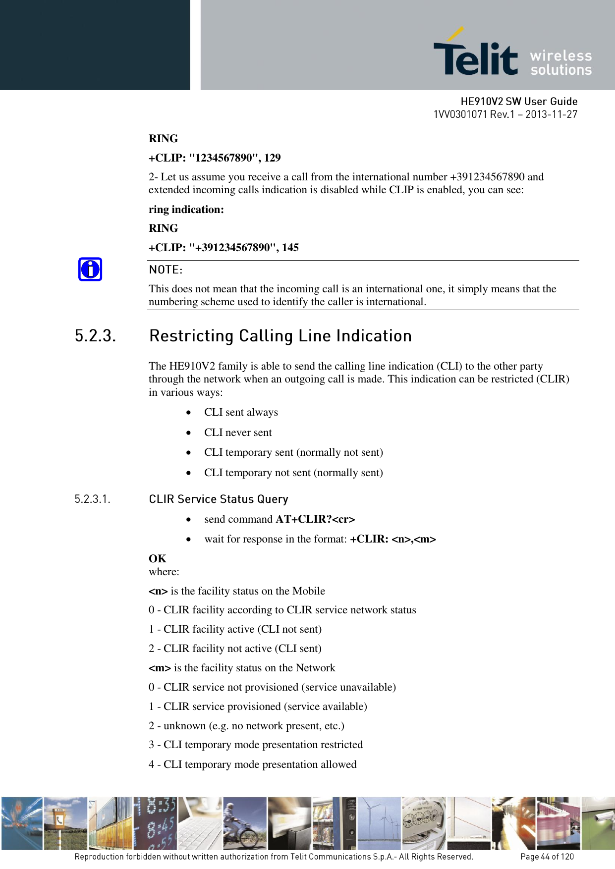
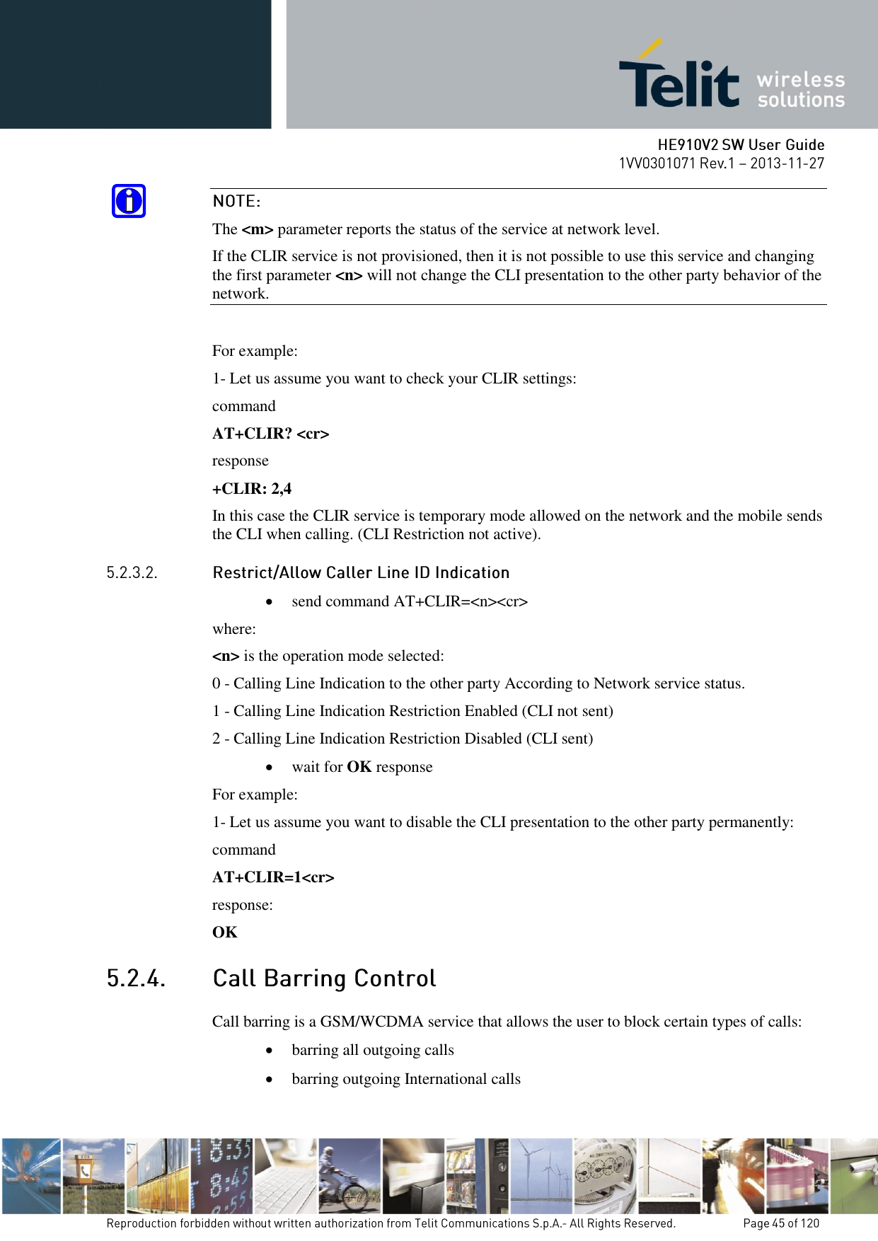
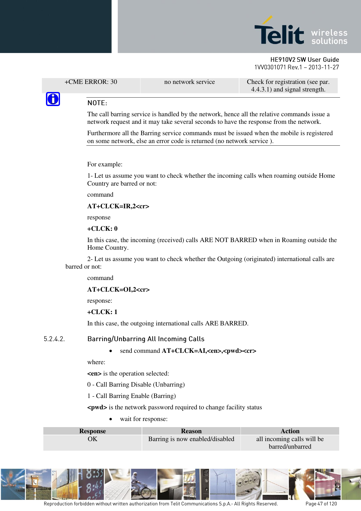
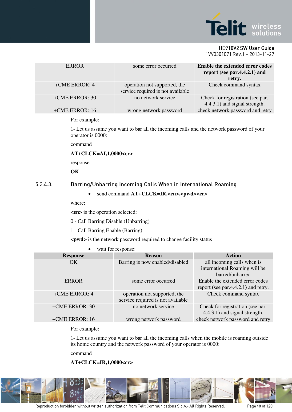
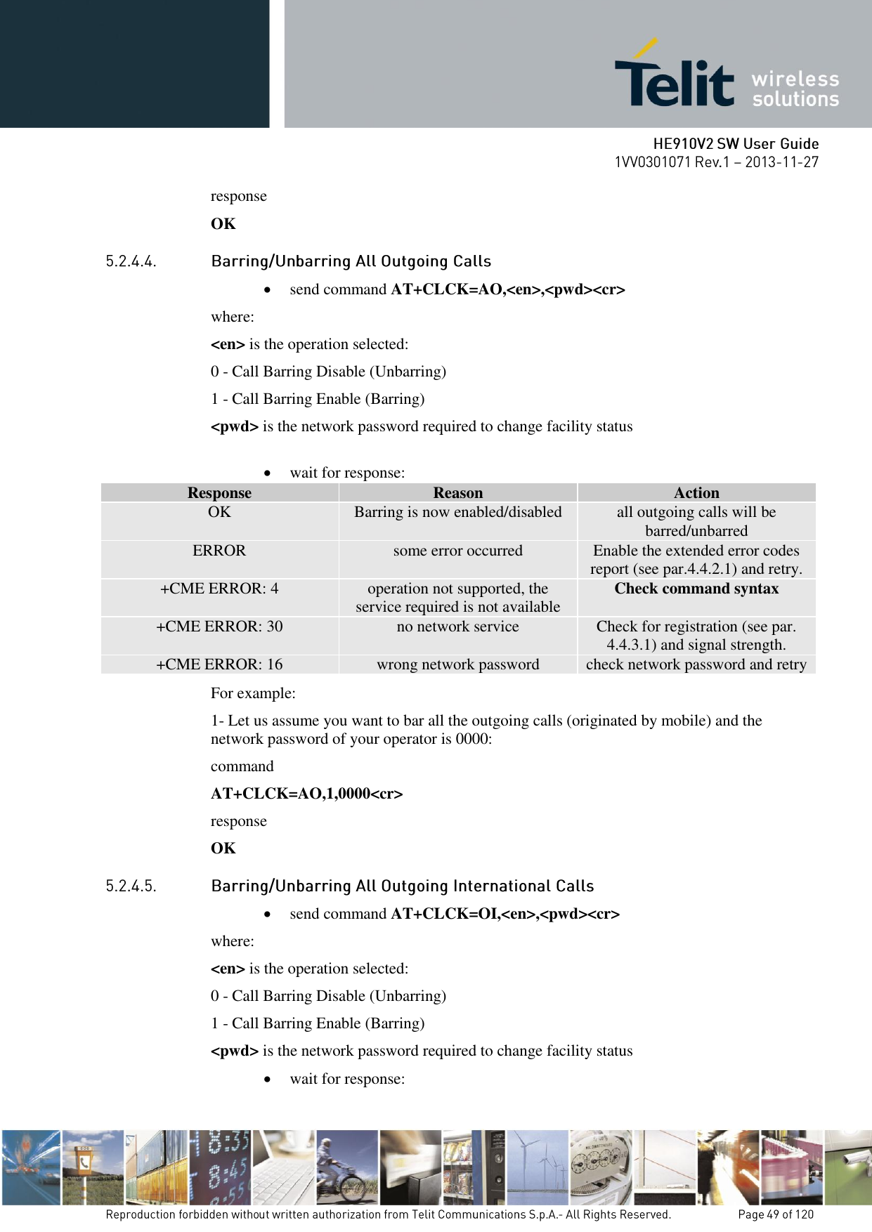
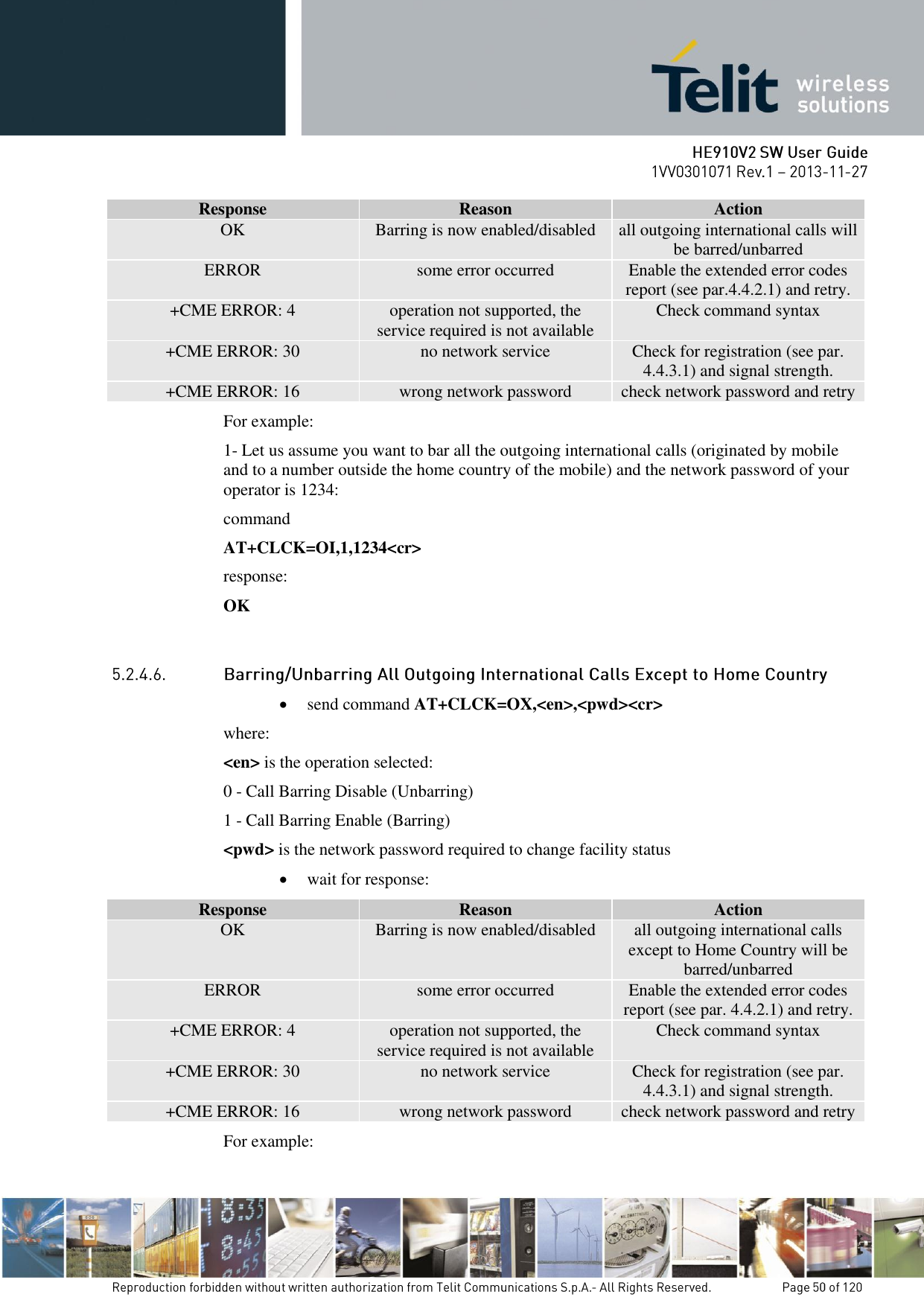
![ barring outgoing International calls except to home country barring all incoming calls barring incoming calls when roaming outside the home country all barring services (applicable only for disabling command) all outgoing barring services (applicable only for disabling command) all incoming barring services (applicable only for disabling command) The service can be queried, enabled and disabled. The call barring service is handled by the network, hence all the relative commands issue a network request and it may take several seconds to get response from the network. Furthermore, all call barring service commands must be issued when the mobile is registered on some Network; otherwise an error code is returned (no network service). send command AT+CLCK=<fac>,2<cr> where: <fac> is the facility to be queried: AO - Barring All Outgoing Calls OI - Barring Outgoing International Calls OX - Barring Outgoing International Calls except to Home Country AI - Barring All Incoming Calls IR - Barring Incoming Calls when Roaming outside the home country AB - All barring services (applicable only for disabling command) AG - All outgoing barring services (applicable only for disabling command) AC - All Incoming barring services (applicable only for disabling command) PP - service Provider Personalization (refer 3GPP TS 22.022 [33]) PC - Corporate Personalization (refer 3GPP TS 22.022 [33]) PF - lock Phone to the very First inserted SIM/UICC card (also referred in the present document as PH-FSIM) (MT asks password when other than the first SIM/UICC card is inserted) wait for response: Response Reason Action +CLCK: 0 facility is disabled calls are allowed +CLCK: 1 facility is enabled calls are barred +CME ERROR: 4 operation not supported, the service required is not available Check command syntax and service code](https://usermanual.wiki/Telit-Communications-S-p-A/HE910NAV2.updated-SW-manual/User-Guide-2159728-Page-46.png)
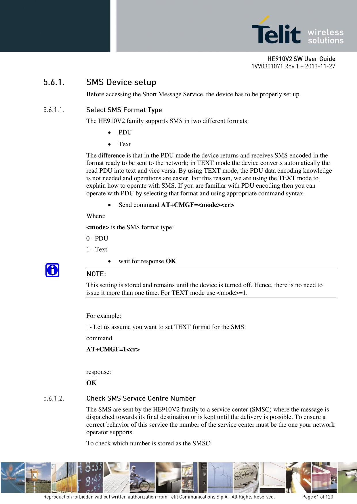

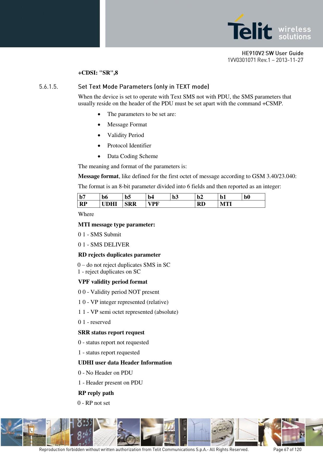
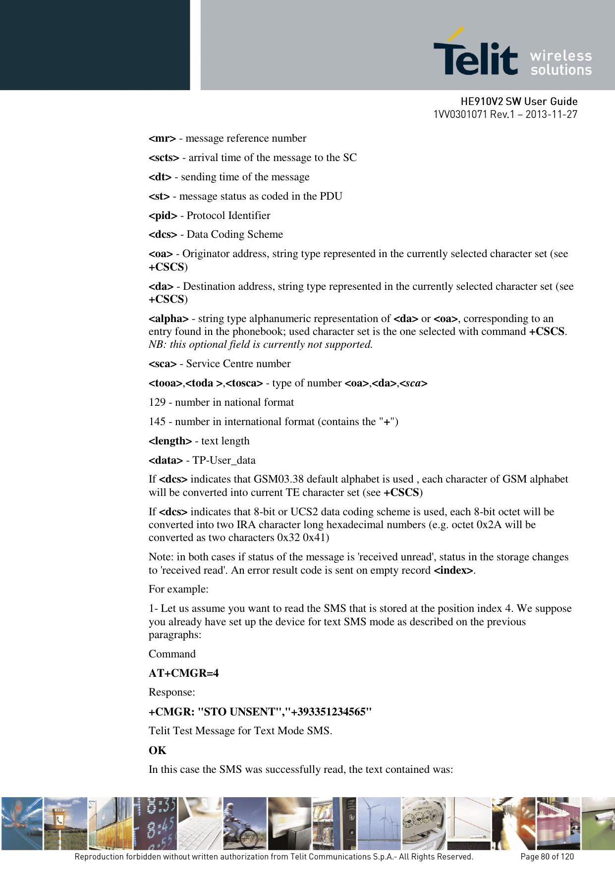
![<index> - location on the memory where SM is stored. 2 - SMS-DELIVERs (except class 2 messages and messages in the message waiting indication group) are routed directly to the TE using the following unsolicited result code: (PDU Mode) +CMT: <alpha>,<length><CR><LF><pdu> where: <alpha> - alphanumeric representation of originator/destination number corresponding to the entry found in MT phonebook <length> - PDU length <pdu> - PDU message (TEXT Mode) +CMT:<oa>,<alpha>,<scts>[,<tooa>,<fo>,<pid>,<dcs>, <sca>,<tosca>,<length>]<CR><LF><data> (the information written in italics will be present depending on +CSDH last setting) where: <oa> - originating address, string type converted in the currently selected character set (see +CSCS) <alpha> - alphanumeric representation of <oa>; used character set must be the one selected with either command +CSCS. <scts> - arrival time of the message to the SC <tooa>, <tosca> - type of number <oa> or <sca>: 129 - number in national format 145 - number in international format (contains the "+") <fo> - first octet of 3gpp 03.40/23.040 <pid> - Protocol Identifier <dcs> - Data Coding Scheme <sca> - Service Centre address, string type, converted in the currently selected character set (see +CSCS) <length> - text length <data> - TP-User-Data Class 2 messages and messages in the message waiting indication group (stored message) result in indication as defined in <mt>=1. 3 - Class 3 SMS-DELIVERs are routed directly to TE using unsolicited result codes defined in <mt>=2. Messages of other data coding schemes result in indication as defined in <mt>=1. <bm> - broadcast reporting option 0 - Cell Broadcast Messages are not sent to the DTE](https://usermanual.wiki/Telit-Communications-S-p-A/HE910NAV2.updated-SW-manual/User-Guide-2159728-Page-64.png)
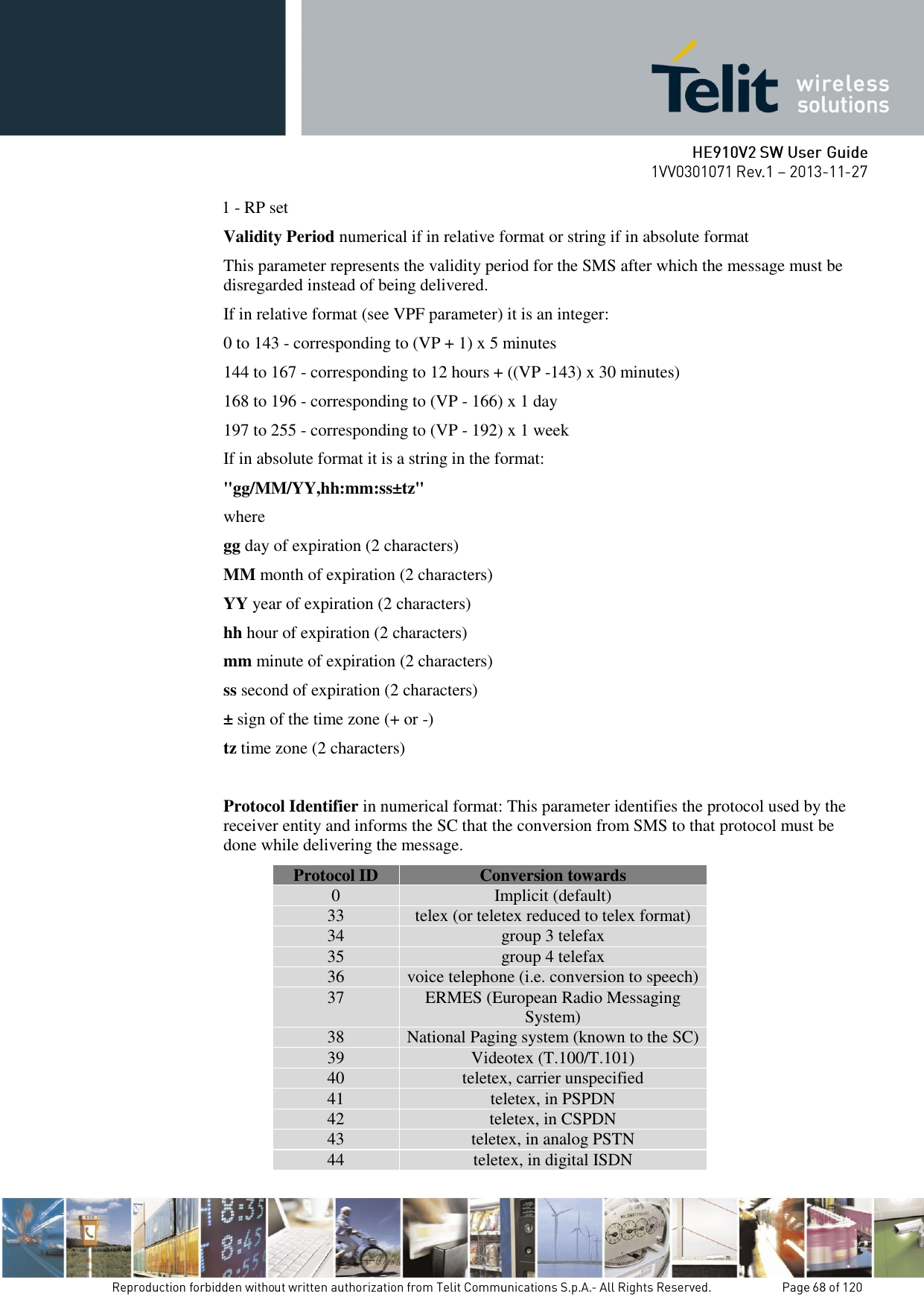
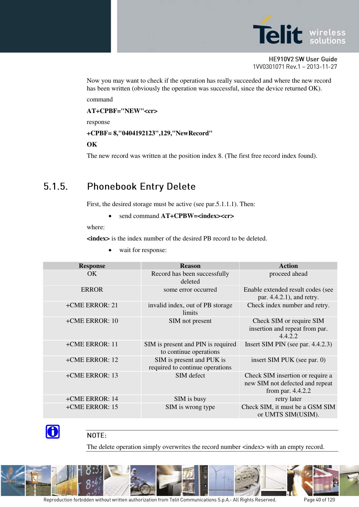
![DTE: +CMTI: "SM",11 AT+CPMS="SM" +CPMS: 11,50,11,50,11,50 OK Use unsolicited indication parameter to read the SMS for the first time. An already written/received SMS can be deleted from the selected storage. To delete the SMS its location index is needed: send command AT+CMGD=<index>[,<delflag>]<cr> where: <index>: SMS location index, if <delflag> = 0 Test command shows the valid memory locations and optionally the supported values of <delflag>. <delflag>: an integer indicating multiple message deletion request as follows: 0 (or omitted) Delete the message specified in <index> 1 Delete all read messages from preferred message storage, leaving unread messages and stored mobile originated messages (whether sent or not) untouched 2 Delete all read messages from preferred message storage and sent mobile originated messages, leaving unread messages and unsent mobile originated messages untouched 3 Delete all read messages from preferred message storage, sent and unsent mobile originated messages leaving unread messages untouched. 4 Delete all messages from preferred message storage including unread messages. wait for response: Response Reason Action OK Message has been successfully deleted. proceed ahead ERROR some error occurred Enable the extended error codes report (see par. 4.4.2.1) and retry. +CMS ERROR: 321 Invalid memory index e.g. the given record was already empty Check the <index> number and retry. For example: 1- Let us assume you want to delete a previously written SMS that was written to the storage index position number 3. We suppose you already have set up the device for text SMS mode as described on the previous paragraphs:](https://usermanual.wiki/Telit-Communications-S-p-A/HE910NAV2.updated-SW-manual/User-Guide-2159728-Page-78.png)
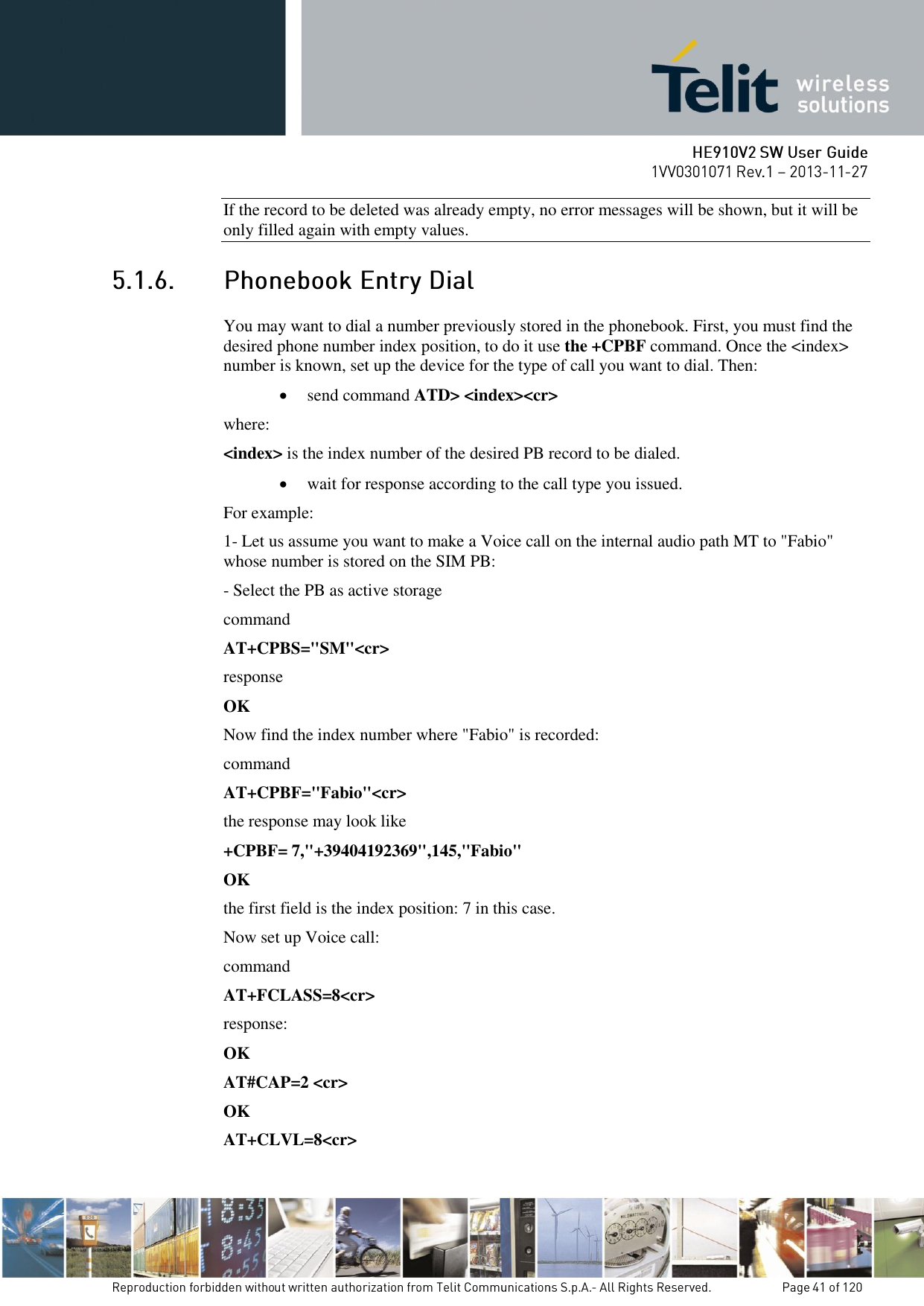
![command AT+CMGD=3 response: OK In this case, the SMS was successfully deleted. 2- Let us assume you want to delete a received SMS that was stored to the index position number 7: command AT+CMGD=7 response: OK A new SMS can be read with the command send command AT+CMGR=<index><cr> where: <index>: SMS location index wait for response in the format: Output format for received messages (the information written in italics will be present depending on +CSDH last setting): +CMGR: <stat>,<oa>,<alpha>,<scts>[,<tooa>,<fo>,<pid>, <dcs>,<sca>,<tosca>,<length>]<CR><LF><data> Output format for sent messages: +CMGR: <stat>,<da>,<alpha>[,<toda>,<fo>,<pid>,<dcs>,, <sca>,<tosca>,<length>]<CR><LF><data> Output format for message delivery confirm: +CMGR: <stat>,<fo>,<mr>,,,<scts>,<dt>,<st> where: <stat> - status of the message "REC UNREAD" - new received message unread "REC READ" - received message read "STO UNSENT" - message stored not yet sent "STO SENT" - message stored already sent <fo> - first octet of the message PDU](https://usermanual.wiki/Telit-Communications-S-p-A/HE910NAV2.updated-SW-manual/User-Guide-2159728-Page-79.png)
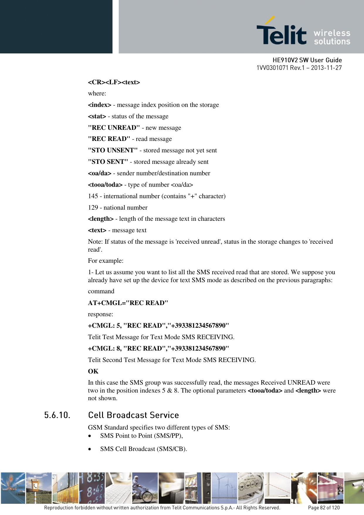
!["Telit Test Message for Text Mode SMS." The message was written to the storage by user (STO) but still not sent (UNSENT) to the destination address with the number +393351234565 2- Let us assume you want now to read the SMS that is stored at the position index 5: Command AT+CMGR=5 Response: +CMGR: "REC UNREAD","+393381234567890", ,"29/06/01,12:30:04+01" Telit Test Message for Text Mode SMS RECEIVING. OK In this case the SMS was successfully read, the text contained was: "Telit Test Message for Text Mode SMS RECEIVING." The message was received (REC) from the number +393381234567890 at 12:30:04 the day 29/06/01 in the European time zone +1. After this read command the message at index 5 becomes REC READ. The SMS can be grouped into 5 different groups depending on their status: REC UNREAD received messages still not read REC READ received messages already read STO UNSENT written messages not yet sent STO SENT written messages already sent ALL all types of messages It is possible to have the list of all the messages in one group: send command AT+CMGL=<stat><cr> Where: <stat> - status group of the message "REC UNREAD" - new message "REC READ" - read message "STO UNSENT" - stored message not yet sent "STO SENT" - stored message already sent "ALL" - all messages wait for response in the format: For every message in the group: +CMGL: <index>,<stat>,<oa/da> [,,,<tooa/toda>,<length>]](https://usermanual.wiki/Telit-Communications-S-p-A/HE910NAV2.updated-SW-manual/User-Guide-2159728-Page-81.png)
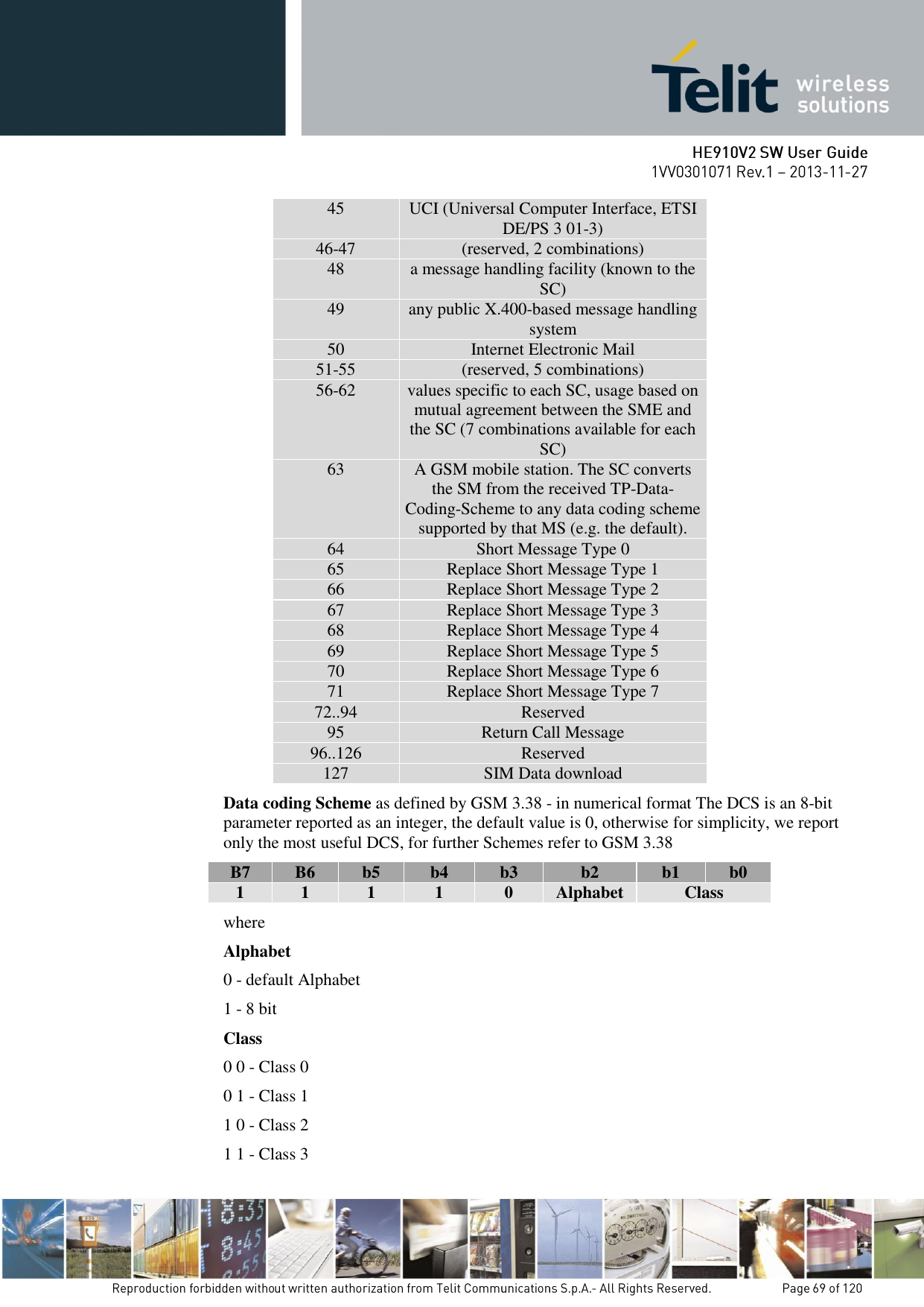
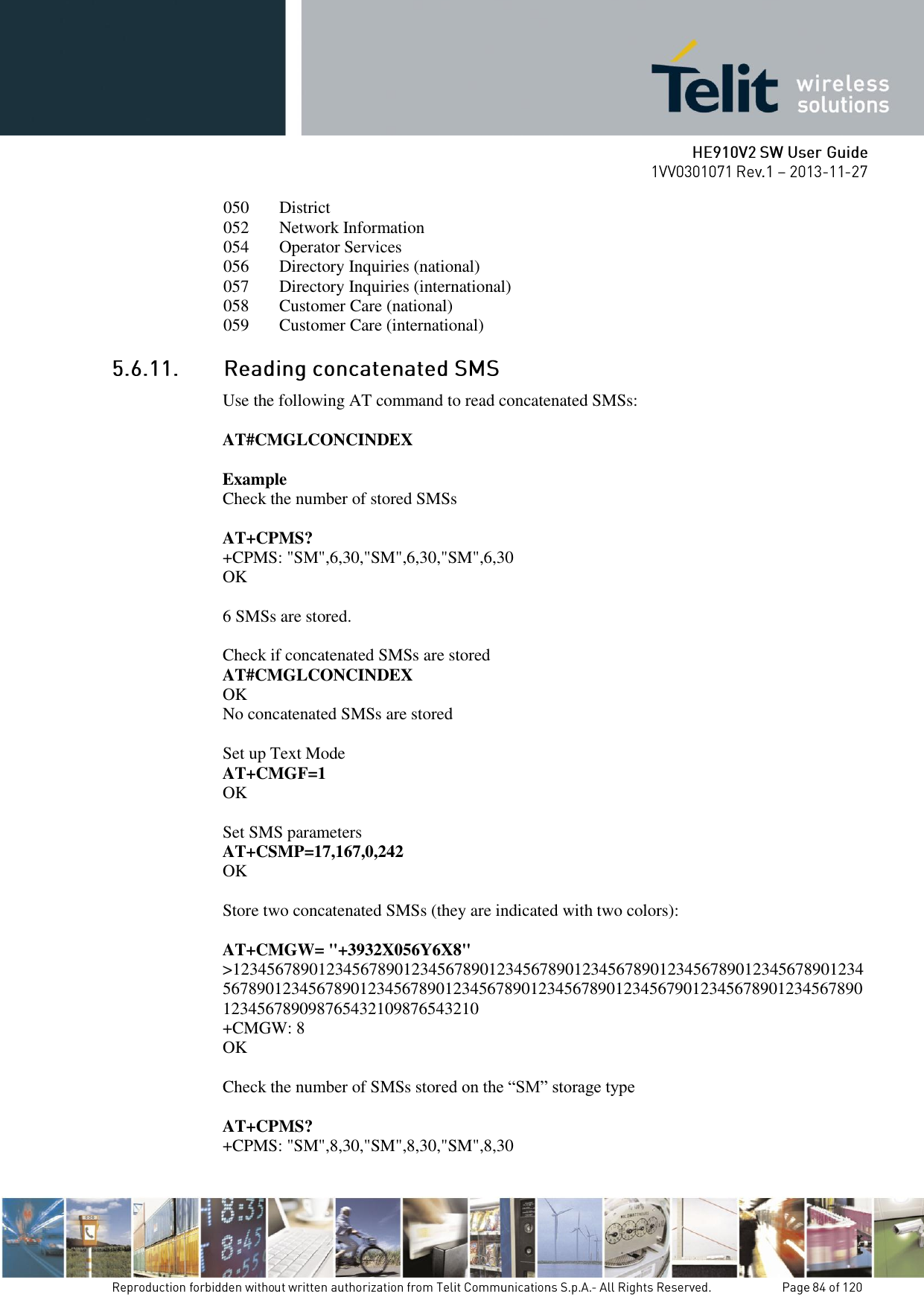
![The first type can send a text message long up to 160 characters from a module to the another (as stated on the previous paragraphs), the second type allows the Network to send, at the same time, a message to all modules contained in the defined area including one or more radio cells. The availability and the implementation of the Cell Broadcast Service are strictly connected with the Network Operator of the subscriber. Use the following AT command to enable the Cell Broadcast Service: AT+CSCB=[<mode>[,<mids>[,<dcss>]]] Example Select Text Mode. AT+CMGF=1 OK Select the District service. AT+CSCB=0,50,0 OK Select how the new received message event is indicated by the DCE to the DTE. AT+CNMI=2,0,2,0,0 OK After a while the “District” broadcast message is displayed on the DTE. +CBM: 24,50,1,1,1 TRIESTE +CBM: 4120,50,2,1,1 TRIESTE +CBM: 8216,50,1,1,1 TRIESTE +CBM: 12312,50,2,1,1 TRIESTE The following list of Services can be provided by the Network Operator, it is not mandatory: <mids> Service name 000 Index 010 Flashes 020 Hospitals 022 Doctors 024 Pharmacy 030 Long Distant Road Reports 032 Local Road Reports 034 Taxis 040 Weather](https://usermanual.wiki/Telit-Communications-S-p-A/HE910NAV2.updated-SW-manual/User-Guide-2159728-Page-83.png)


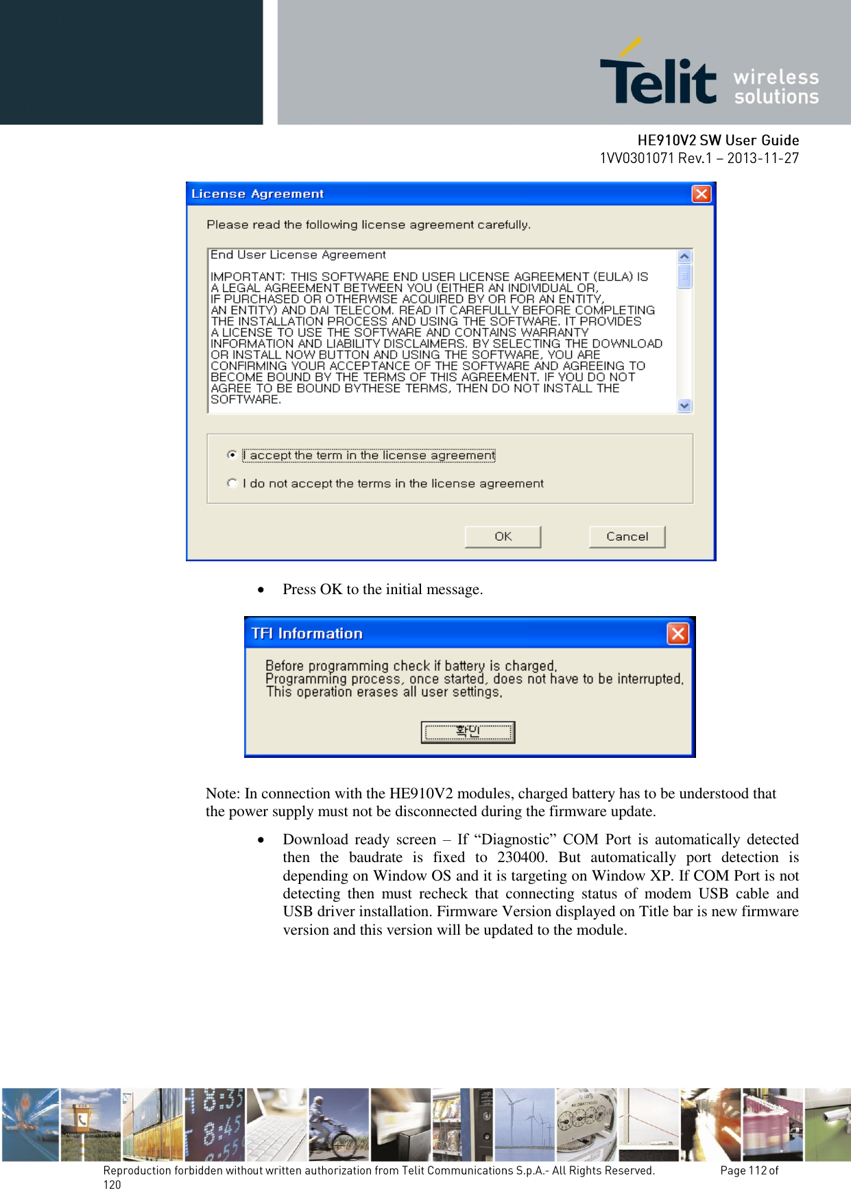
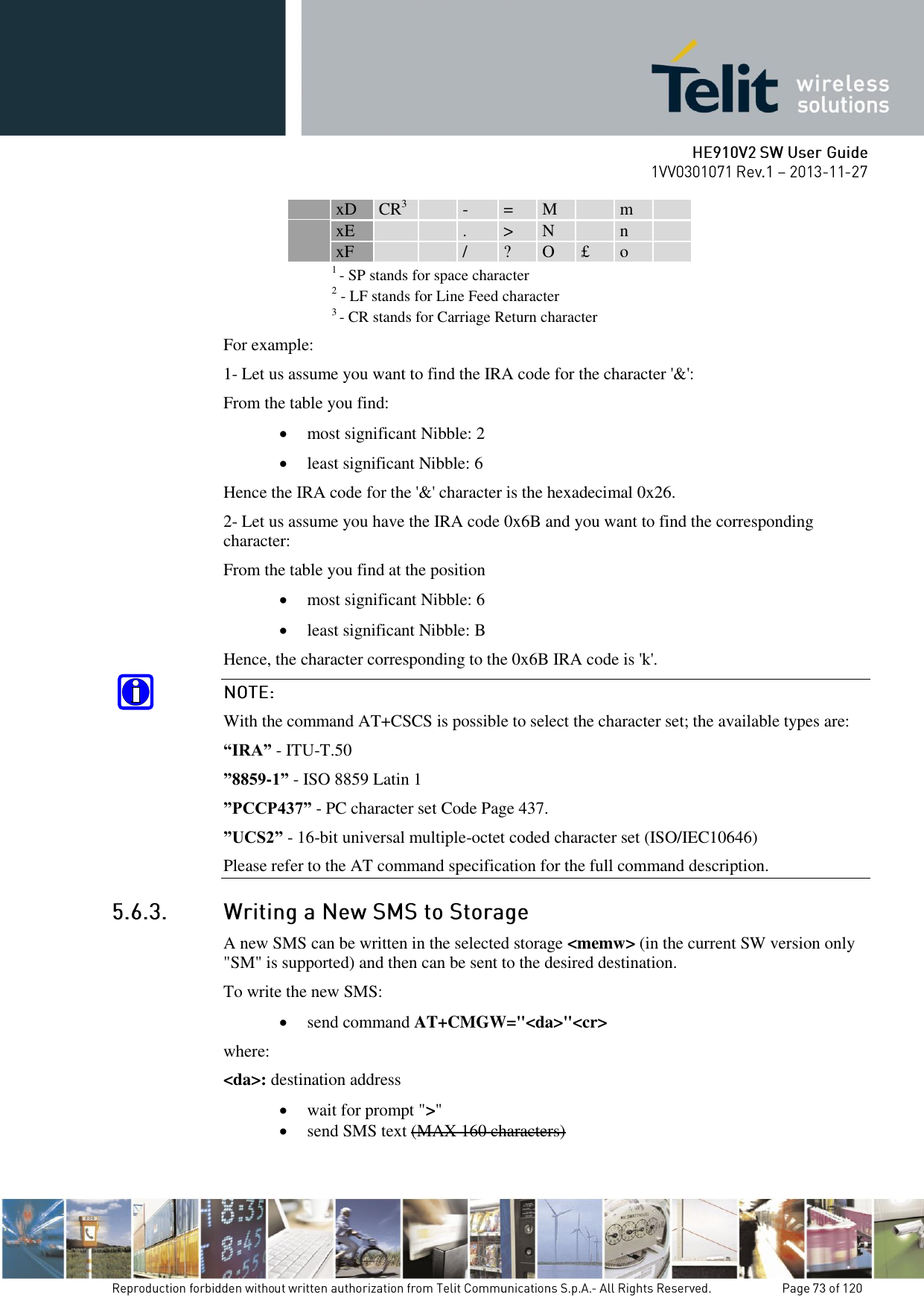
![The Telit Modules firmware is updated through the Serial Interface normally used for the AT Commands. It is suggested to provide an RS232 interface on the User Printed Circuit Board (where the Telit Module is soldered) to perform the physical connection between the Telit module and a Windows-based PC. That simple circuitry makes the firmware updating easy when a new firmware version is released. During the User Application development or evaluation phase of the Telit module, the RS232 interface or the USB port implemented on the Telit Evaluation Kit (EVK2) [6] can be used to connect the Telit module to a Windows-based PC on which a dedicated tool for firmware updating is running. Telit provides the User with two tools to update the firmware of the module. The following paragraphs describe them. GT terminals are complete encased modems. They do not need the Telit Evaluation Kit (EVK2) to perform testing, evaluation and Firmware Update. The firmware update can be done with a specific software tool provided by Telit that runs on Windows based PCs. First the program will erase the content of flash memory, and then the program will write on the flash memory. To update the firmware of the module, we suggest the following procedure: Run the file TFI_xxxx.exe. The following window must be displayed, select the language preferred by pressing the correspondent button. The End User License Agreement will appear. Please, read it and accept the terms if you are going to proceed.](https://usermanual.wiki/Telit-Communications-S-p-A/HE910NAV2.updated-SW-manual/User-Guide-2159728-Page-111.png)