Telit Communications S p A HE910NAV2 2G/3.5G module, HE910-NAG V2, HE910-NA V2 User Manual SW User Guide
Telit Communications S.p.A. 2G/3.5G module, HE910-NAG V2, HE910-NA V2 SW User Guide
Contents
- 1. updated SW manual
- 2. Updated Hardware manual
updated SW manual


SPECIFICATIONS SUBJECT TO CHANGE WITHOUT NOTICE
Notice
While reasonable efforts have been made to assure the accuracy of this document, Telit
assumes no liability resulting from any inaccuracies or omissions in this document, or from
use of the information obtained herein. The information in this document has been carefully
checked and is believed to be entirely reliable. However, no responsibility is assumed for
inaccuracies or omissions. Telit reserves the right to make changes to any products described
herein and reserves the right to revise this document and to make changes from time to time
in content hereof with no obligation to notify any person of revisions or changes. Telit does
not assume any liability arising out of the application or use of any product, software, or
circuit described herein; neither does it convey license under its patent rights or the rights of
others.
It is possible that this publication may contain references to, or information about Telit
products (machines and programs), programming, or services that are not announced in your
country. Such references or information must not be construed to mean that Telit intends to
announce such Telit products, programming, or services in your country.
Copyrights
This instruction manual and the Telit products described in this instruction manual may be,
include or describe copyrighted Telit material, such as computer programs stored in
semiconductor memories or other media. Laws in the Italy and other countries preserve for
Telit and its licensors certain exclusive rights for copyrighted material, including the
exclusive right to copy, reproduce in any form, distribute and make derivative works of the
copyrighted material. Accordingly, any copyrighted material of Telit and its licensors
contained herein or in the Telit products described in this instruction manual may not be
copied, reproduced, distributed, merged or modified in any manner without the express
written permission of Telit. Furthermore, the purchase of Telit products shall not be deemed
to grant either directly or by implication, estoppel, or otherwise, any license under the
copyrights, patents or patent applications of Telit, as arises by operation of law in the sale of a
product.
Computer Software Copyrights
The Telit and 3rd Party supplied Software (SW) products described in this instruction manual
may include copyrighted Telit and other 3rd Party supplied computer programs stored in
semiconductor memories or other media. Laws in the Italy and other countries preserve for
Telit and other 3rd Party supplied SW certain exclusive rights for copyrighted computer
programs, including the exclusive right to copy or reproduce in any form the copyrighted
computer program. Accordingly, any copyrighted Telit or other 3rd Party supplied SW
computer programs contained in the Telit products described in this instruction manual may
not be copied (reverse engineered) or reproduced in any manner without the express written
permission of Telit or the 3rd Party SW supplier. Furthermore, the purchase of Telit products
shall not be deemed to grant either directly or by implication, estoppel, or otherwise, any
license under the copyrights, patents or patent applications of Telit or other 3rd Party supplied
SW, except for the normal non-exclusive, royalty free license to use that arises by operation
of law in the sale of a product.

Usage and Disclosure Restrictions
License Agreements
The software described in this document is the property of Telit and its licensors. It is
furnished by express license agreement only and may be used only in accordance with the
terms of such an agreement.
Copyrighted Materials
Software and documentation are copyrighted materials. Making unauthorized copies is
prohibited by law. No part of the software or documentation may be reproduced, transmitted,
transcribed, stored in a retrieval system, or translated into any language or computer language,
in any form or by any means, without prior written permission of Telit
High Risk Materials
Components, units, or third-party products used in the product described herein are NOT
fault-tolerant and are NOT designed, manufactured, or intended for use as on-line control
equipment in the following hazardous environments requiring fail-safe controls: the operation
of Nuclear Facilities, Aircraft Navigation or Aircraft Communication Systems, Air Traffic
Control, Life Support, or Weapons Systems (High Risk Activities"). Telit and its supplier(s)
specifically disclaim any expressed or implied warranty of fitness for such High Risk
Activities.
Trademarks
TELIT and the Stylized T Logo are registered in Trademark Office. All other product or
service names are the property of their respective owners.
This document is intended for customers integrating HE910V2 modules in their project.
For general contact, technical support, to report documentation errors and to order manuals,
contact Telit Technical Support Center (TTSC) at:
TS-EMEA@telit.com
TS-NORTHAMERICA@telit.com
TS-LATINAMERICA@telit.com
TS-APAC@telit.com
Alternatively, use:
http://www.telit.com/en/products/technical-support-center/contact.php
For detailed information about where you can buy the Telit modules or for recommendations
on accessories and components visit:
http://www.telit.com
To register for product news and announcements or for product questions contact Telit
Technical Support Center (TTSC).
Our aim is to make this guide as helpful as possible. Keep us informed of your comments and
suggestions for improvements.
Telit appreciates feedback from the users of our information.
This document contains the following chapters:
“Chapter 1: “Introduction” provides a scope for this document, target audience, contact and
support information, and text conventions.
“Chapter 2: “Overview” gives an overview of the features described in the document.
“Chapter 3: “HE910V2 Family Products Specification” describes in details the characteristics
of the product, providing information such as power supply requirements, mechanical
dimensions and interfaces specifics.
“Chapter 4: “Basic operations”: gives an overview on the basic operations using AT
command: switch on/off, formatting, response, placing a voice call, etc.
“Chapter 5: “Advanced operations”: gives an overview on the advanced operations: access to
phonebook, call handling, messages, GPIO setting, alarms, power consumption management
etc.
“Chapter 6: “Packet switched data operations”: deals on the GPRS data management. It
describes Enhanced Easy GPRS features.
“Chapter 7: “GPS operations”: describes GPS handling for HE910-EUG V2 and HE910-NAG
V2. It provides an overview on NMES sentences, message formatting, GPS power
management and serial ports for communications.
“Chapter 8: “Service and firmware update” describers the procedure and software tools used
to update the firmware of HE910V2.
“Chapter 9: “Document History” describers document history for HE910V2.
Danger – This information MUST be followed or catastrophic equipment failure or bodily
injury may occur.
Caution or Warning – Alerts the user to important points about integrating the module, if
these points are not followed, the module and end user equipment may fail or malfunction.
Tip or Information – Provides advice and suggestions that may be useful when
integrating the module.
All dates are in ISO 8601 format, i.e. YYYY-MM-DD.
HE910V2 Hardware user guide 1vvxxx
HE910V2 AT commands reference guide 80418ST10126A
The purpose of this document is the description of some common AT command procedures
that may be used with the Telit HE910V2 family module. In this document, all the basic
functions of a mobile phone are taken into account and for each one of them; a proper
command sequence will be suggested. In the Advanced operation section the more useful
services and features of the GSM and WCDMA network supported by the Telit HE910V2
family module is taken into account and some command sequence and usage are provided for
each one of them. This document and its suggested command sequences must not be
considered mandatory; instead, the information given must be used as a guide for properly
using the Telit module. For further commands and features that may not be explained in this
document refer to the HE910V2 family Product Description document where all the
supported AT commands are reported.
NOTE:
The integration of the HE910V2 module within user application shall be done according to
the design rules described in this manual
The information presented in this document is believed to be accurate and reliable. However,
Telit Communications S.p.A. assumes no responsibility for its use, nor any infringement of
patents or other rights of third parties, which may result from its use. No license is granted by
implication or otherwise under any patent rights of Telit Communications S.p.A. other than
for circuitry embodied in Telit products. This document is subject to change without notice.
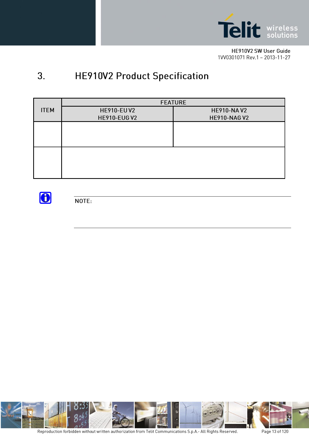
Air
interface
▪ Tri-band UMTS/HSPA 900/2100
▪ Quad-Band GSM850/900/1800/1900
▪ Tri-band UMTS/HSPA 850/2100
▪ Quad-Band GSM850/900/1800/1900
Data
Service
HSPA UL 5.76 Mbps, DL 14Mbps
WCDMA UL/DL 384kbps,
EDGE UL/,DL 236.8Kbps,
GPRS UL/DL 85.6 Kbps, CSD 9.6Kbps
In the following sections, HE910V2 family refers to all HE910V2 products mentioned in the
table above. Whenever a command and/or feature is referred to a specific model, it is clearly
highlighted
In the next paragraphs the following notations are used:
<cr> represents the Carriage Return Character (13)
<lf> represents the Line Feed Character (10)
<xx> represents a parameter with changing name is in place of the double x. (< and >
characters are only for limiting the parameter and must not be issued to the terminal).
[<xx>] represents an optional parameter whatever name is in place of the xx.
[ and ] characters are only for limiting the optional parameter and must not be issued to the
terminal).
Every command issued to the Telit modules returns a result response if response codes are
enabled (default). The time needed to process the given command and return the response
varies, depending on the command type. Commands that do not interact with the SIM or the
network, and involve only internal set up settings or readings, have an immediate response,
depending on SIM configuration(e.g., number of contacts stored in the phonebook, number of
stored SMS), or on the network the command may interact with.
In the table below are listed only the commands whose interaction with the SIM or the
network could lead to long response timings. When not otherwise specified, timing is referred
to set command. For phonebook and SMS writing and reading related commands, timing is
referred to commands issued after phonebook sorting is completed. For DTMF sending and
dialing commands timing is referred to module registered on network (“AT+CREG?” answer
is “+CREG: 0,1” or “+CREG: 0,5”).
+COPS
125 (test command)
+CLCK
15 (SS operation)
5 (FDN enabling/disabling)
+CPWD
15 (SS operation)
5 (PIN modification)
+CLIP
15 (read command)
+CLIR
15 (read command)
+CCFC
15
In case no response is received after the timeout time has been elapsed, then try repeating the
last command and if still no response is received until the timeout time, an Unconditional
Shutdown MUST be issued and the device must be powered ON again.

+CCWA
15
+CHLD
60
+CPIN
30
+CPBS
5 (FDN enabling/disabling)
+CPBR
5 (single reading)
15 (complete reading of a 500 records full phonebook)
+CPBF
10 (string present in a 500 records full phonebook)
5 (string not present)
+CPBW
5
+CACM
5
+CAMM
5
+CPUC
180
+VTS
20 (transmission of full “1234567890*#ABCD” string with no delay
between tones, default duration)
+CSCA
5 (read and set commands)
+CSAS
5
+CRES
5
+CMGS
120 after CTRL-Z; 1 to get ‘>’ prompt
+CMSS
120 after CTRL-Z; 1 to get ‘>’ prompt
+CMGW
5 after CTRL-Z; 1 to get ‘>’ prompt
+CMGD
5 (single SMS cancellation)
25 (cancellation of 50 SMS)
+CNMA
120 after CTRL-Z; 1 to get ‘>’ prompt
+CMGR
5
+CMGL
100
+CGACT
150
+CGATT
90
D
120 (voice call)
Timeout set with ATS7 (data call)
A
60 (voice call)
Timeout set with ATS7 (data call)
H
60
+CHUP
6
+COPN
10
+COPL
180
+CRSM
180
+FRH
Timeout set with ATS7
+FTH
Timeout set with ATS7
+FRM
Timeout set with ATS7
+FTM
Timeout set with ATS7
+FRS
Timeout set with the command itself
+FTS
Timeout set with the command itself
+WS 46
10
#MBN
10
#TONE
5 (if no duration specified)
#EMAILD
60
#EMAILACT
150
#SEMAIL
210 ( context activation + DNS resolution )
#MSCLASS
15
#STSR
30
#GPRS
150
#SKTD
140 (DNS resolution + timeout set with AT#SKTCT)
#SKTOP
290 ( context activation + DNS resolution + timeout set with
AT#SKTCT)
#QDNS
170
#FTPOPEN
120 (timeout set with AT#FTPTO, in case no response is received
from server)
#FTPCLOSE
500 (timeout set with AT#FTPTO, in case no response is received
from server)
#FTPTYPE
500 (timeout set with AT#FTPTO, in case no response is received
from server)
#FTPDELE
500 (timeout set with AT#FTPTO, in case no response is received
from server)
#FTPPWD
500 (timeout set with AT#FTPTO, in case no response is received
from server)
#FTPCWD
500 (timeout set with AT#FTPTO, in case no response is received
from server)
#FTPLIST
500 (timeout set with AT#FTPTO, in case no response is received
from server) + time to get listing
#FTPPUT
500 (timeout set with AT#FTPTO, in case no response is received
from server)
#SGACT
150
#SH
10
#SD
140 (DNS resolution + connection timeout set with AT#SCFG)
#CSURV
125
#CSURVC
125
#CSURVUC
125
#CSURVB
125
#CSURVBC
125
#CSURVP
125
#CSURVPC
125
Please refer to HE910V2 Hardware User Guide
After a proper power on, the device is ready to receive AT commands on the USB or serial
port.
Several things must be checked in order to be sure that the device is ready to send and receive
calls and SMS.
HE910V2 family does not support autobauding. Users have to set the right speed for serial
communication before device initialization. If HE910V2 family set the right speed, the device
responds with OK. The default baudrate is 115200.
send command AT+IPR=<rate><cr>
wait for OK response
where rate is the port speed and can be
300,600,1200,2400,4800,9600,19200,38400,57600,115200,230400,460800,3200000,4000000
bps.
The USB or serial port suggested setting is: port speed 115200, character format 8N1 (8 bit
per char, No parity bit, and 1 stop bit)
The first thing to check is the SIM presence and PIN code insertion. This can be done with the
following commands:
send command AT+CMEE=1<cr>
wait for OK response
or if you prefer the verbose format instead of the numerical format then: send
command AT+CMEE=2<cr>
wait for OK response
send command AT+CPIN?<cr>
wait for response:
Response
Reason
Action
+CPIN: SIM PIN
SIM is present and PIN is required to continue
operations
Proceed to par. 4.4.2.3
+CPIN: SIM PUK
SIM is present and 10 attempts to give SIM
PIN have failed, so SIM is blocked
Send command
AT+CPIN=<SIM PUK>
+CPIN: SIM PIN2
SIM is present and 3 attempts to give SIM
PIN2 have failed, so SIM PUK2 is required
Proceed to par. 4.4.2.3
+CPIN: SIM PUK2
SIM is present and 10 attempts to give SIM
PUK2 have failed, so SIM PIN2 cannot use
anymore.
Send command
AT+CPIN=<SIM PUK>
+CPIN: READY
SIM is present and no PIN code is required to
proceed
Proceed ahead
+CME ERROR: 10
SIM is not inserted
Insert SIM or require SIM
insertion and repeat from par.
4.4.2.2
+CME ERROR: 13
SIM is failure
Check SIM insertion or require a
new SIM not defected and repeat
from par. 4.4.2.2
+CME ERROR: 14
SIM is busy
retry later
+CME ERROR: 15
SIM is wrong type
Check SIM, it must be a GSM SIM
or UMTS SIM(USIM).
+CME ERROR: 770
SIM is permanent blocked
Change valid SIM card
send command AT+CPIN=****<cr> where **** stands for the SIM PIN code
(e.g. 1234)
wait for response:
Response
Reason
Action
OK
SIM PIN was correct
Proceed ahead
ERROR
the PIN code inserted is not correct
Retry from par. 4.4.2.2
When receiving the ERROR message, repeat Query SIM presence and status since after 3
failed attempts SIM PIN is not requested anymore, but SIM PUK is requested instead. You
may need to go through procedure 0
send command AT+CPIN=*******,<newpin><cr> where ******* stands for
the SIM PUK code (e.g. 12345678) and <newpin> (e.g. 1234) will replace the
old pin in the SIM.
wait for response:
Response
Reason
Action
OK
SIM PUK was correct
Proceed ahead
ERROR
the SIM PUK code inserted is not correct
Retry from par. 0
When receiving the ERROR message, be careful to check if the SIM PUK is correct before
trying again. After 10 failed attempts to provide the SIM PUK the SIM Card will lock and
will not be usable anymore.
send command AT+CREG?<cr>
wait for response:
Response
Reason
Action
+CME ERROR: 10
SIM not present or damaged
Check SIM or require SIM
insertion and repeat from par.
4.4.2.2
+CME ERROR: 11
SIM is present and PIN is required to
continue operations
Repeat par. 4.4.2.3
+CREG: 0,0
or
+CREG: 1,0
No network is found
Check for antenna cable
connection (antenna may be
disconnected or damaged) or
change position if the antenna is
OK. Repeat par. 4.4.3.1 until a
network is found.
+CREG: 0,1
or
+CREG: 1,1
Mobile is registered on its home network.
Proceed ahead. Ready to call
+CREG: 0,2
or
+CREG: 1,2
Mobile is currently not registered on any
network but is looking for a suitable one to
register.
Repeat procedure at par. 4.4.3.1 to
see if it has found a suitable
network to register in.
+CREG: 0,3
or
+CREG: 1,3
Mobile has found some networks but it is not
allowed to register on any of them, no
roaming was allowed.
Try in another place, and repeat
procedure at par. 4.4.3.1
+CREG: 0,4
or
+CREG: 1,4
Mobile is in an unknown network status
Repeat procedure at par. 4.4.3.1 to
see if it has found a suitable
network to register in
+CREG: 0,5
or
+CREG: 1,5
Mobile has found some networks and is
currently registered in roaming on one of
them
Proceed ahead. Ready to call
When a response +CREG: x,1 or +CREG: x,5 is received, then the device is ready to place
and receive a call or SMS. It is possible to jump directly to call setup procedures or SMS
sending procedures.
Once the mobile has registered on some network (or even if it has returned +CREG:x,3), it is
possible to query the mobile for network identifications, codes and names:
send command AT+COPS=?<cr>
wait for response in the format:
+COPS: : [list of supported (<stat>,long alphanumeric <oper>,short alphanumeric
<oper>,numeric <oper>,< AcT>)s]
[,,(list of supported <mode>s),(list of supported <format>s)]
where:
<stat> - operator availability
0 - unknown
1 - available
2 - current
3 - forbidden
<AcT> access technology selected:
0 GSM
2 UTRAN
Since with this command a network scan is done, this command may require some seconds
before the output is given.
For example:
command
AT+COPS=?<cr>
Answer:
+COPS: (2,"I WIND","WIND","22288",2),(1,"SI MOBITEL
GSM","","29341",0),(1,"Vodafone IT","OMNITEL","22210",2), (3,"I
TIM","TIM","22201",0),,(0-4),(0-2)
OK
In this case the mobile is registered on the network "I WIND" which is a network from Italy,
code: 222 and Network ID: 88. There is also another network available for registration:
"SI MOBITEL GSM" which is a network from Slovenia, code: 293 and Network ID: 41 ,
"SI.MOBIL" which is a network from Slovenia, code: 293 and Network ID: 40 and
Vodafone IT from Italy with Nation code 22 and Network 10.
The other network is not available for registration:
This command issues a network request and it may require quite a long time to respond, since
the device has to wait the answer from the network (it can be as long as 60 seconds). Do not
use this command if not necessary.
"I TIM" from Italy, code: 222 and Network ID: 01 – FORBIDDEN
In this case an "I TIM" logo might be reproduced on the MMI to give the user the
information that is registered on that network.
Once the mobile has registered on one network, it may be useful to know the received signal
strength & quality to give the user an indication of the reliability of the network.
send command AT+CSQ<cr>
wait for response in the format:
<WCDMA network >
+CSQ: <rssi>,99
OK
<GSM network>
+CSQ: <rssi>,<ber>
OK
where:
<rssi> is an integer from 0 to 99 that indicates the received signal strength:
<rssi> value
Signal Strength
Indication
0
-113 dBm or less
Signal is VERY low: at the extreme sensibility limit
1
-111 dBm
MMI may indicate only 1 antenna bar
2
-109 dBm
MMI may indicate only 1 antenna bar
3
-107 dBm
MMI may indicate only 1 antenna bar
4
-105 dBm
MMI may indicate only 1 antenna bar
5
-103 dBm
MMI may indicate only 1 antenna bar
6
-101 dBm
MMI may indicate 2 antenna bars
7
-99 dBm
MMI may indicate 2 antenna bars
8
-97 dBm
MMI may indicate 2 antenna bars
9
-95 dBm
MMI may indicate 2 antenna bars
10
-93 dBm
MMI may indicate 3 antenna bars
11
-91 dBm
MMI may indicate 3 antenna bars
12
-89 dBm
MMI may indicate 3 antenna bars
13
-87 dBm
MMI may indicate 3 antenna bars
14
-85 dBm
MMI may indicate 3 antenna bars
15
-83 dBm
MMI may indicate 4 antenna bars
16
-81 dBm
MMI may indicate 4 antenna bars
17
-79 dBm
MMI may indicate 4 antenna bars
18
-77 dBm
MMI may indicate 4 antenna bars
19
-75 dBm
MMI may indicate 4 antenna bars
20
-73 dBm
MMI may indicate 4 antenna bars
21
-71 dBm
MMI may indicate 4 antenna bars
22
-69 dBm
MMI may indicate 4 antenna bars
23
-67 dBm
MMI may indicate 4 antenna bars
24
-65 dBm
MMI may indicate 4 antenna bars
25
-63 dBm
MMI may indicate 4 antenna bars
26
-61 dBm
MMI may indicate 4 antenna bars
27
-59 dBm
MMI may indicate 4 antenna bars
28
-57 dBm
MMI may indicate 4 antenna bars
29
-55 dBm
MMI may indicate 4 antenna bars
30
-53 dBm
MMI may indicate 4 antenna bars
31
-51 dBm or more
MMI may indicate 4 antenna bars
99
not detected
MMI may indicate flashing antenna bars
When <rssi> is less than 6, with only 1 MMI antenna bar, the quality of a call will be poor
and the call may even drop.
<ber> is an integer from 0 to 7 and 99 that reports the received signal quality measured on the
radio traffic channel.
The quality is measured on the traffic channel. It is available only during a conversation. In
Idle the reported value must not be considered.
In conversation the quality decreases with the increase of the <ber> number.
The <ber> value refers strictly to the GSM radio channel and is a very technical parameter. It
can be used to monitor the voice call quality since the voice quality is inversely proportional
to the <ber> number. HE910V2 family doesn’t support ber in WCDMA network so the
return value fixed as 99.
Once the mobile has registered on one network, it may be useful to know the received signal
strength and the network on which the mobile is registered. These information can be
gathered with the commands +CREG, +COPS and +CSQ, which are part of the standard
3gpp GSM 07.07/27.007 commands as seen before, unfortunately these commands are not so
fast in the response due to network response time, especially the +COPS command. If You

want to keep your software as general as possible you can follow the indications given before
and forget this part; instead if you need or want a faster way to check at the mobile network
information, the HE910V2 family provides a special command #MONI which can be used to
gather all the information needed in a faster and simpler way:
send command AT#MONI=0<cr>
wait for OK response
send command AT#MONI?<cr>
wait for response in the format:
When extracting data for the serving cell and the network name is known the
format is:
(GSM network)
#MONI: <netname> BSIC:<bsic> RxQual:<qual> LAC:<lac> Id:<id>
ARFCN:<arfcn> PWR:<dBm> dBm TA: <timadv>
(WCDMA network)
#MONI: <netmame> PSC:<psc> RSCP:<rscp> LAC:<lac> Id:<id> EcIo:<ecio>
UARFCN:<uarfcn> PWR:<dBm> dBm DRX:<drx> SCR:<scr>
When the network name is unknown, the format is:
(GSM network)
#MONI: Cc:<cc> Nc:<nc> BSIC:<bsic> RxQual:<qual> LAC:<lac> Id:<id>
ARFCN:<arfcn> PWR:<dBm> dBm TA: <timadv>
(WCDMA network)
#MONI: Cc:<cc> Nc:<nc> PSC:<psc> RSCP:<rscp> LAC:,<lac> Id:<id>
EcIo:<ecio> UARFCN:<uarfcn> PWR:<dBm> dBm DRX:<drx> SCR:<scr>
When extracting data for an adjacent cell, the format is:
(GSM network)
#MONI: Adj Cell<n> [LAC:<lac> Id:<id>] ARFCN:<arfcn> PWR:<dBm> dBm
(WCDMA network)
#MONI: PSC:<psc> RSCP:<rscp> EcIo:<ecio> UARFCN:<uarfcn> SCR:<scr>
Where:
<netname> - name of network operator
<cc> - country code
<nc> - network operator code
<n> - progressive number of adjacent cell
<bsic> - base station identification code
<qual> - quality of reception
0..7
<lac> - localization area code
<id> - cell identifier
<arfcn> - assigned radio channel
<dBm> - received signal strength in dBm
<timadv> - timing advance
<psc> - primary synchronisation code
<rscp> - Received Signal Code Power in dBm
<ecio> - chip energy per total wideband power in dBm
<uarfcn> - UMTS assigned radio channel
<drx> - Discontinuous reception cycle length
<scr> - Scrambling code
TA: <timadv> is reported only for the serving cell.
When the last setting done is AT#MONI=7, then the Read command reports the above pieces
of information for each of the cells in the neighbor of the serving cell, formatting them in a
sequence of <CR><LF>-terminated strings. Currently this is available in case of GSM
network.
For example (WCDMA):
at#moni=0<cr>
OK
At#moni<cr>
#MONI: Welcome to KTF PSC:270 RSCP:-76 LAC:5121 EcIo:-3.5 UARFCN:10812
PWR:-73 dBm DRX:64
OK
at#moni=1<cr>
OK
at#moni<cr>
#MONI: Sync NSet PSC:408 RSCP:-86 EcIo:-13.5 UARFCN:10812
#MONI: Sync NSet PSC:102 RSCP:-104 EcIo:-31.5 UARFCN:10812
OK
In this case the mobile is registered on the network whose Country code is 010 and Network
operator code is 03, the signal strength is -83dBm (MMI may indicate 4 antenna bars as
reported on the table 5). Other information received is strictly technical and must not be given
to the user.
The values reported are random and have no meaning. They are used only to explain
command usage.
This command must be used only to gather information on network name and signal strength,
to check if mobile is registered or is looking for a suitable network to register. Always use the
+CREG command. This is due to the fact that if the network signal is too weak and mobile
loses the registration. Until a new network is found the #MONI command reports the last
measured valid values and not the real ones.
The TA (timing advance parameter) is valid only during a call.
To properly use this feature, check network registration with command +CREG as seen on
par. 2.7.3.1 and when mobile is registered query the mobile for network operator name and
signal strength with #MONI command.
Before a voice call can be placed, it is recommended to check if the mobile is registered on a
network (see par. 4.4.3.1) and if the signal strength is enough to ensure a call can be made.
send command AT+FCLASS=8<cr>
wait for OK response
This command may be omitted if the modifier ";" is added at the end of the ATD command
after the dialed number.
The HE910V2 family has three different audio paths:
PCM microphone/ear(PCM)
Usually the internal path is used for a handset function, while the external is used for
handsfree function. There are two ways to switch between these two paths:
SOFTWARE: by using the command AT#CAP= <n> (with n=1 OR n=2)
HARDWARE: by setting AT#CAP=0 and setting the AXE input high (internal
MT) or low (external HF).
If only one path is needed, then it is preferable to use the internal one (MT).
When Hardware control is not needed AXE pin can be left unconnected.
The audio paths can also be switched in both ways during a call.

send command AT#CAP=<n><cr>
Where:
<n> = 0 for HARDWARE control with AXE input
<n> = 1 for external HF path (regardless of the AXE input status)
<n> = 2 for internal MT path (regardless of the AXE input status)
wait for OK response
For example:
1 - Let us assume that the desired audio path is always the internal MT
Command
AT#CAP=2<cr>
Answer
OK
2 - Let us assume that the desired audio path has to be determined by HARDWARE pin AXE
Command
AT#CAP=0<cr>
Answer
OK
Now set the hardware pin AXE in the desired status.
Set the desired volume on the active audio path speaker output
This setting is not strictly necessary; it is also possible to keep the default volume setting.
send command AT+CLVL=<vol><cr>
Where:
<vol> is a number between 0 and 10 representing the volume setting:
0 - minimum volume
10 - maximum volume
wait for OK response
The volume setting refers to the ACTIVE path ear line and is stored each time. When
changing audio path, the volume setting will be reset to the previously stored value for that
audio path.
The microphone of the active path can be muted with an AT command; to be sure that it is not
muted, it is suggested to check it with this command
• Send command AT+CMUT?<cr>
• wait for response in the format:
+CMUT: <mute>
OK
where:
<mute> is the muting setting for the microphone:
0 - microphone active
1 - microphone muted
The mute setting is different from Volume setting: it refers to both the audio paths, the mute
setting will remain even when changing audio path.
Send command ATD <PhoneNumber><cr>
where:
<PhoneNumber> is the phone number to be dialed
wait for response:
Response
Reason
Action
OK
The call has been placed
Wait for the other party to lift the
receiver
BUSY
The line called is busy
retry later
NO ANSWER
The receiver did not answer the
call
retry later
NO CARRIER
Call placing has not been
successful
check for mobile registration and
signal strength
For example:
1- Let us assume you have to call the national number 040 - 4192111,
command
ATD 0404192111<cr>
response
OK
2- Let us assume you have to call the national number but in international format +39-40-
4192111,
command
ATD +39404192111<cr>
response
OK
3- Let us assume you have to call the international number +386-40-4192111 without
previously setting the +FCLASS=8 (voice),
command
ATD +386404192111;<cr>
response
OK
send command AT+CHUP<cr>
wait for response OK
During the voice call the device remains in command mode, so the escape sequence (+++)
must not be issued before sending commands.
Before a data call can be placed, it is recommended to check if the mobile is registered on a
network (see par. 2.7.3.1) and if the signal strength is enough to ensure that a call can be made.
send command AT+FCLASS=0<cr>
wait for OK response
The +FCLASS setting is maintained in the memory and there is no need to repeat this
command if +FCLASS setting is not changed.
The data connection can be made using different modulations at different speeds. This
connection mode can be selected with the command +CBST. The syntax for the command is:
AT+CBST=<mod>,0,<ce>
These parameters can be selected as seen in the table:
<WCDMA network>
Command
Modulation
Speed
[bps]
Connection Element
AT+CBST=0,0,1
V.32
9600
non transparent
AT+CBST=14,0,1
V.34
14400
non transparent
AT+CBST=16,0,1
V.34
28800
non transparent
AT+CBST=17,0,1
V.34
33600
non transparent
AT+CBST=43,0,1
V.120
14400
non transparent
AT+CBST=48,0,1
V.120
28800
non transparent
AT+CBST=51,0,1
V.120
56000
non transparent
AT+CBST=75,0,1
V.110/ X.31
14400
non transparent
AT+CBST=80,0,1
V.110 / X.31
28800
non transparent
AT+CBST=81,0,1
V.110 / X.31
38400
non transparent
AT+CBST=83,0,1
V.110/ X.31
56000
non transparent
AT+CBST=83,4,1
V.110/ X.31
56000 RDI
non transparent
AT+CBST=84,0,1
X.31
64000
non transparent
AT+CBST=116,1,0
Bit transparent
64000
transparent
AT+CBST=134,1,0
multimedia
64000
transparent
<GSM network>
Command
Modulation
Speed
[bps]
Connection Element
AT+CBST=0,0,1
V.32
9600
non transparent
AT+CBST=7,0,1
V.32
9600
non transparent
AT+CBST=12,0,1
V.34
9600
non transparent
AT+CBST=14,0,1
V.34
14400
non transparent
AT+CBST=39,0,1
V.120
9600
non transparent
AT+CBST=43,0,1
V.120
14400
non transparent
AT+CBST=71,0,1
V110/ X.31
9600
non transparent
AT+CBST=75,0,1
V.110/ X.31
14400
non transparent
AT+CBST=7,0,0
V.32
9600
transparent
AT+CBST=12,0,0
V.34
9600
transparent
AT+CBST=14,0,0
V.34
14400
transparent
Once selected the appropriate <mod > and <ce> parameters from the table:
send command AT+CBST=<mod>,0,<ce><cr>
wait for OK response
send command ATD <PhoneNumber><cr>
where:
<PhoneNumber> is the phone number to be dialed
wait for response:
Response
Reason
Action
CONNECT 9600
The called modem is now on line.
exchange data
BUSY
The line called is busy
retry later
NO ANSWER
The receiver did not answer the call
retry later
NO CARRIER
The modem handshaking has not been
successful
Check for mobile registration and
signal strength and eventually
retry.
The response to the ATD command is returned after the modem handshaking, this takes about
30 seconds, so allow this time before doing anything.
When the device is doing the handshake the issue of any character closing the handshake
aborts the call.
For example:
1- Let us assume you have to call the national number 040 - 4192111,
command
ATD 0404192111<cr>
response
CONNECT 9600
2- Let us assume you have to call the national number but in international format +39-40-
4192111,
command
ATD +39404192111<cr>
response
CONNECT 9600
3- Let us assume you have to call the international number +386-40-4192111,
command
ATD +386404192111<cr>
response
CONNECT 9600
send escape sequence +++
wait for response OK
send command ATH<cr>
wait for response NO CARRIER
During the data call the device remains in data (on line) mode, so the escape sequence (+++)
must be issued before sending AT commands to the device.
When an incoming call is detected, the device reports an unsolicited code, which may be:
Unsolicited code
Reason
RING
The extended format of incoming call indication is disabled and a call
(voice or data) is incoming.
+CRING: VOICE
The extended format of incoming call indication is enabled and a voice
call is incoming.
+CRING: ASYNC
The extended format of incoming call indication is enabled and an
asynchronous transparent data call is incoming.
+CRING: REL ASYNC
The extended format of incoming call indication is enabled and an
asynchronous reliable (not transparent) data call is incoming.
+CRING: SYNC
The extended format of incoming call indication is enabled and a
synchronous transparent data call is incoming.
+CRING: REL SYNC
The extended format of incoming call indication is enabled and a
synchronous reliable (not transparent) data call is incoming.
To answer the call:
send command ATA<cr>
wait for response:
Response
Reason
Action
CONNECT 9600
The incoming call was a DATA
one and called modem is now on
line.
exchange data
ERROR
No incoming call is found, call
may have been lost
call lost
NO CARRIER
The incoming call was a DATA
one and the modem handshaking
has not been successful
check for mobile registration
and signal strength and modem
settings.
OK
The incoming call was a VOICE
call and is now active.
proceed ahead
The call is answered with the appropriate type (VOICE or DATA) regardless of the
+FCLASS active setting. To distinguish between Data and Voice see the command response
or the extended format incoming call indication.
The Telit HE910V2 family provides the flow control method to avoid the unexpected data loss, while data
communication is activating via serial interface such as UART,USB.
Below table describes the flow control method can be selected in serial interface
SW Flow
control
(Xon/Xoff)
HW Flow
control
(RTS/CTS)
No Flow
control
Remark
UART1
O
O
O
Flow control method can be set by
AT\Q, AT&K , AT+IFC
USB MDM
O
Only support for RTS/CTS
USB AUX
O
No support flow control
USB AUX doesn’t support any flow control method. Therefore, this port isn’t suitable for
DATA service port. We recommend this port should be used only for AT command and URC
processing
In case TE sends RTS signal or XOff to Modem to stop data flow from Modem, Modem’s transmission can’t
be stopped, instantly. There are some delay times Modem process RTS signal.
Therefore, TE should prepare the guarding buffer after sending RTS signal or XOff to Modem to control data
flow. Below table describes the size of guarding buffer, according to serial interface and air access technology,
approximately
GSM/WCDMA
Circuit Service
GPRS/EGPRS/WCDMA
Packet Service
HSDPA
UART1
1 Kbyte
1.5 Kbyte
1.5 Kbyte
USB MDM
1 Kbyte
1.5 Kbyte
4 Kbyte
TE should prepare the guarding buffer more than the recommended buffer size to guarantee their data
transmission without the loss of data
The HE910V2 family can access the phonebook storage of the SIM card inserted, by using
specific AT commands it is possible to store and recall phone numbers and their associated
name.
The HE910V2 family supports several SIM phonebook storages:
“DC” - MT dialed calls list (+CPBW may not be applicable for this storage)
“EN” - SIM/USIM (or MT) emergency number (+CPBW is not be applicable
for this storage)
"FD" - SIM/USIM fixed dialing-phonebook. If a SIM card is present or if a
UICC with an active GSM application is present, the information in EFFDN under
EFTelecom is selected. If a UICC with an active USIM application is present, the
information in EFFDN under ADFUSIM is selected.
"LD" - SIM/UICC last-dialing-phonebook "MC" - MT missed(unanswered
received) calls list (+CPBW may not be applicable for the storage) “ME” - MT
phonebook
“ME” - MT phonebook
“ON” - SIM(or MT) own numbers (MSISDNs) list (reading of this storage may
be available through +CNUM also). When storage information in the SIM/UICC,
if a SIM card is present or if a UICC with an active USIM application is present,
the information in EFMSISDN under DFTelecom is selected. If a UICC with an active
USIM application is present, the information in EFMSISDN under ADFUSIM is
selected.
"RC" - MT received-calls-list (+CPBW and +CPBF are not applicable for this
storage)
"MC" - device missed (unanswered received) calls list (+CPBF is not applicable
for this storage)
“MB” - mailbox numbers stored on SIM; it is possible to select this storage only
if the mailbox service is provided by the SIM (see #MBN).
This is the list of the received calls calling numbers, it is updated automatically at each call
received and insertion or search on it is not possible. The only operations allowed are recall,
read and delete.
“SM” - SIM/UICC phonebook. If a SIM card is present or if a UICC with an
active GSM application is present, EFADN under DFTelecom is selected. If a UICC
with active USIM application is present, the global phonebook, DFPHONEBOOK
under DFTelecom is selected.
In order to access the storage, you have to choose which one will be active. This must be
always the first PB operation. Once the storage is selected, it is not needed anymore to select
it again until the desired storage remains the one active and the device is not turned off.
send command AT+CPBS=<storage>[<,passwrod>]<cr>
where:
<storage> is the desired PB storage:
“DC” - MT dialed calls list (+CPBW may not be applicable for this storage)
“EN” - SIM/USIM (or MT) emergency number (+CPBW is not be applicable for this
storage)
“FD” - SIM/USIM fixed dialing phonebook
“LD” - SIM/USIM last dialing phonebook
“MC” - missed calls list
“MB” - mailbox numbers stored on SIM
“ME” - MT phonebook
“ON” - SIM (or MT) own numbers (MSI storage may be available through +CNUM also).
“RC” - received calls list
“SM” - SIM/USIM phonebook
<password>: string type value representing the PIN2-code required when selecting PIN2-
code locked <storage>s above, e.g. "FD" or the hidden key to be verified in order to access
to the hidden phonebook entries in the SIM/USIM or any other phonebook with hidden
entries.
wait for response:
Response
Reason
Action
OK
selected PB is now active
Proceed ahead
ERROR
some error occurred
Enable extended result codes (see
par. 4.4.2.1)
and retry.
+CME ERROR: 10
SIM not present
Check SIM or require SIM
insertion and repeat from par.
4.4.2.2
+CME ERROR: 11
SIM is present and PIN is required
to continue operations
Insert SIM PIN (see par. 4.4.2.3)
+CME ERROR: 12
SIM is present and PUK is
required to continue operations
insert SIM PUK (see par. 0)
+CME ERROR: 13
SIM defect
Check SIM insertion or require a
new SIM not defected and repeat
from par. 4.4.2.2
+CME ERROR: 14
SIM is busy
retry later
+CME ERROR: 15
SIM is wrong type
Check SIM, it must be a GSM SIM
or UMTS SIM(USIM).
+CME ERROR: 17
PIN2 is required to continue
Enable FD facility with +CLCK
operations, since FD facility is not
enabled.
(see par.5.1.1.2)
and retry.
After power up & PIN authentication the device reads all the SIM for a backup, hence SIM
access is inhibited (SIM is busy after the issue of the PIN or after power up if PIN request is
disabled) for a time varying from few seconds to about a minute, depending on the percentage
of written records in the SIM phonebook. If Phonebook commands are issued during this time
the device returns an error message. If this happens, the operations will start again later.
Due to the particular features of the FD storage, when selecting the FD storage the PIN2 must
be inserted or the FD facility must be enabled.
If +CPBS command reports +CME ERROR: 17 then enable the facility with command
+CLCK (see par. 3.1.1.2)
For example:
1- Let us assume you want to select the "SM" normal phonebook for operations,
command
AT+CPBS="SM"<cr>
response
OK
2- Let us assume you want to select the "MC" missed calls list for operations,
command
AT+CPBS="MC"<cr>
response
OK
3. Let us assume you want to select the “FD” fixed dialing phonebook for operations
command
AT+CPBS="FD",”0000”<cr>
response
OK
send command AT+CLCK=FD,1,<PIN2><cr>
where:
<PIN2> is the PIN2 code of the SIM.
wait for response:
Response
Reason
Action
OK
FD facility is now enabled
Return to select PB (see par.
5.1.1.1)
ERROR
some error occurred
Enable extended result codes (see
par. 4.4.2.1), check if the PIN2 is
correct
and retry.
+CME ERROR: 17
the inserted PIN2 is wrong
Check PIN2 code and retry.
When receiving the ERROR or +CME ERROR message, repeat Query SIM presence and
status since after 3 failed attempts SIM PIN2 is not requested anymore, SIM PUK2 is
requested instead. You may need to go through procedure 2.7.2.4 (but insert PUK2 instead of
PUK1)
First, you must select the "SM" storage as active (see par.5.1.1.1).
send command AT+CPBF=<text><cr>
where:
<text> is the desired string to be found in the name field of the PB record.
wait for response in the format:
+CPBF= <index>,"<number>",<type>,"<text>"
OK
where:
<index> is the record number on the PB;
<Number> is the phone number;
<type> is the type of number:
145 - international numbering scheme
129 - national numbering scheme
<text> is the alphanumeric name associated with the number or in the case no corresponding
entries are found:
+CME ERROR: 22 or simply ERROR.
The search for <text> string is not case sensitive and the string may or may not be included in
double brackets

For example:
1- Let us assume you want to select the "SM" normal phonebook for operations,
command
AT+CPBS="SM"<cr>
response
OK
Now you might want to look for the entries with the name starting with: "FA"
command
AT+CPBF="FA"<cr>
the response may look like:
+CPBF= 7,"+39404192369",145,"Fabio"
+CPBF= 9,"0404192111",129,"Fabrizio"
OK
Now you might want to look for the entries with the name starting with: "FAUSTO" but no
record contains this name:
command
AT+CPBF="FAUSTO"<cr>
response
+CME ERROR: 22
or if extended error codes are disabled simply
response
ERROR
First, you must select the desired storage as active (see par. 5.1.1.1). Then:
send command AT+CPBR=<index>[,<index2>]<cr>
where:
<index> is the index number of the desired PB record to be read.
wait for response in the format:
+CPBR= <index>,"<number>",<type>,"<text>"
OK
where:
<index> is the record number on the PB;

<Number> is the phone number;
<type> is the type of number:
145 - international numbering scheme
129 - national numbering scheme
<text> is the alphanumeric name associated with the number or in the case the index number
does not correspond to a written record:
+CME ERROR: 22 or simply ERROR.
For example:
1- Let us assume you want to select the "SM" normal phonebook for operations,
command
AT+CPBS="SM"<cr>
response
OK
Now you might want to look for the entry at the position index = 7
command
AT+CPBR=7<cr>
the response may look like
+CPBR= 7,"+39404192369",145,"Fabio"
OK
Now you might want to look for the entries at the positions from 7 to 9 and for example the
position at index 8 is empty
command
AT+CPBR=7,9<cr>
the response may look like
+CPBR= 7,"+39404192369",145,"Fabio"
+CPBR= 9,"0404192111",129,"Fabrizio"
OK
First you must select the desired storage as active (see par. 5.1.1.1). Then:
send command AT+CPBW=<index>,<number>,<type>,<text><cr>
where:

<index> is the index number of the desired PB record to be written (may be omitted if any
empty record number can be used).
<Number> is the phone number;
<type> is the type of number:
145 - international numbering scheme (contains the character "+")
129 - national numbering scheme
<text> is the alphanumeric name associated with the number.
wait for response:
Response
Reason
Action
OK
Record has been successfully
written
Proceed ahead
ERROR
some error occurred
Enable extended result codes (see
par. 4.4.2.1), and retry.
+CME ERROR: 10
SIM not present
Check SIM or require SIM
insertion and repeat from par.
4.4.2.2
+CME ERROR: 11
SIM is present and PIN is required
to continue operations
Insert SIM PIN (see par. 4.4.2.3)
+CME ERROR: 12
SIM is present and PUK is
required to continue operations
insert SIM PUK (see par. 0)
+CME ERROR: 13
SIM defect
Check SIM insertion or require a
new SIM not defected and repeat
from par. 4.4.2.2
+CME ERROR: 14
SIM is busy
retry later
+CME ERROR: 15
SIM is wrong type
Check SIM, it must be a GSM SIM
or UMTS SIM(USIM).
+CME ERROR: 21
invalid index
Change index number or leave it
empty and retry.
+CME ERROR: 20
memory full
PB storage is full.
For example:
1- Let us assume you want to select the "SM" normal phonebook for operations,
command
AT+CPBS="SM"<cr>
response
OK
Now you might want to write a new record on the PB:
command
AT+CPBW=,"0404192123",129,"NewRecord"<cr>
response
OK
Now you may want to check if the operation has really succeeded and where the new record
has been written (obviously the operation was successful, since the device returned OK).
command
AT+CPBF="NEW"<cr>
response
+CPBF= 8,"0404192123",129,"NewRecord"
OK
The new record was written at the position index 8. (The first free record index found).
First, the desired storage must be active (see par.5.1.1.1). Then:
send command AT+CPBW=<index><cr>
where:
<index> is the index number of the desired PB record to be deleted.
wait for response:
Response
Reason
Action
OK
Record has been successfully
deleted
proceed ahead
ERROR
some error occurred
Enable extended result codes (see
par. 4.4.2.1), and retry.
+CME ERROR: 21
invalid index, out of PB storage
limits
Check index number and retry.
+CME ERROR: 10
SIM not present
Check SIM or require SIM
insertion and repeat from par.
4.4.2.2
+CME ERROR: 11
SIM is present and PIN is required
to continue operations
Insert SIM PIN (see par. 4.4.2.3)
+CME ERROR: 12
SIM is present and PUK is
required to continue operations
insert SIM PUK (see par. 0)
+CME ERROR: 13
SIM defect
Check SIM insertion or require a
new SIM not defected and repeat
from par. 4.4.2.2
+CME ERROR: 14
SIM is busy
retry later
+CME ERROR: 15
SIM is wrong type
Check SIM, it must be a GSM SIM
or UMTS SIM(USIM).
The delete operation simply overwrites the record number <index> with an empty record.

If the record to be deleted was already empty, no error messages will be shown, but it will be
only filled again with empty values.
You may want to dial a number previously stored in the phonebook. First, you must find the
desired phone number index position, to do it use the +CPBF command. Once the <index>
number is known, set up the device for the type of call you want to dial. Then:
send command ATD> <index><cr>
where:
<index> is the index number of the desired PB record to be dialed.
wait for response according to the call type you issued.
For example:
1- Let us assume you want to make a Voice call on the internal audio path MT to "Fabio"
whose number is stored on the SIM PB:
- Select the PB as active storage
command
AT+CPBS="SM"<cr>
response
OK
Now find the index number where "Fabio" is recorded:
command
AT+CPBF="Fabio"<cr>
the response may look like
+CPBF= 7,"+39404192369",145,"Fabio"
OK
the first field is the index position: 7 in this case.
Now set up Voice call:
command
AT+FCLASS=8<cr>
response:
OK
AT#CAP=2 <cr>
OK
AT+CLVL=8<cr>
OK
AT+CMUT? <cr>
+CMUT: 0
and dial
ATD> 7<cr>
OK
The HE910V2 family is able to identify the call type before answering it. It is possible to have
different ring indications (unsolicited codes) depending on the call type:
Unsolicited code
Reason
RING
The extended format of incoming call indication is
disabled and a call (voice or data) is incoming.
+CRING: VOICE
The extended format of incoming call indication is
enabled and a voice call is incoming.
+CRING: ASYNC
The extended format of incoming call indication is
enabled and an asynchronous transparent data call is
incoming.
+CRING: SYNC
The extended format of incoming call indication is
enabled and a synchronous transparent data call is
incoming.
+CRING: REL ASYNC
The extended format of incoming call indication is
enabled and an asynchronous not transparent data call is
incoming.
+CRING: REL SYNC
The extended format of incoming call indication is
enabled and a synchronous not transparent data call is
incoming.
In order to use this feature you must enable the extended format of incoming calls
send command AT+CRC=<n><cr>
where:
<n> is the operation mode selected:
0 - extended results Disabled (device reports RING only)
1 - extended results Enabled (device reports +CRING: <type> indication)

wait for OK response
The HE910V2 family is able to identify the caller number and give indication of it before the
call is answered. The calling number is presented after each RING or +CRING indication in
the format:
+CLIP: "<number>",<type>[,"<subaddress>",<satype>[,"<alpha>"[,<CLI validity>]]]
OK
where:
<Number> is the phone number;
<type> is the type of number:
145 - international numbering scheme
129 - national numbering scheme
<subaddress> is the subaddress of the calling party
<satype> is the type of subaddress
<alpha> is an optional string type alphanumeric representation of <number> corresponding
to the entry found in phonebook;
<CLI validity> is the validity status of CLI presentation:
0 CLI valid.
1 CLI has been withheld by the originator.
2 CLI is not available due to interworking problems or limitation or originating network.
In order to use this feature you must enable the caller ID indication presentation, if feature is
disabled then no CLI indication is given after the RING or +CRING code.
send command AT+CLIP=<n><cr>
where:
<n> is the operation mode selected:
0 - Calling Line Indication Presentation Disabled
1 - Calling Line Indication Presentation Enabled
wait for OK response
For example:
1- Let us assume you receive a call from the national number 1234567890 and extended
incoming calls indication is disabled while CLIP is enabled, you can see:
ring indication:
RING
+CLIP: "1234567890", 129
2- Let us assume you receive a call from the international number +391234567890 and
extended incoming calls indication is disabled while CLIP is enabled, you can see:
ring indication:
RING
+CLIP: "+391234567890", 145
This does not mean that the incoming call is an international one, it simply means that the
numbering scheme used to identify the caller is international.
The HE910V2 family is able to send the calling line indication (CLI) to the other party
through the network when an outgoing call is made. This indication can be restricted (CLIR)
in various ways:
CLI sent always
CLI never sent
CLI temporary sent (normally not sent)
CLI temporary not sent (normally sent)
send command AT+CLIR?<cr>
wait for response in the format: +CLIR: <n>,<m>
OK
where:
<n> is the facility status on the Mobile
0 - CLIR facility according to CLIR service network status
1 - CLIR facility active (CLI not sent)
2 - CLIR facility not active (CLI sent)
<m> is the facility status on the Network
0 - CLIR service not provisioned (service unavailable)
1 - CLIR service provisioned (service available)
2 - unknown (e.g. no network present, etc.)
3 - CLI temporary mode presentation restricted
4 - CLI temporary mode presentation allowed
The <m> parameter reports the status of the service at network level.
If the CLIR service is not provisioned, then it is not possible to use this service and changing
the first parameter <n> will not change the CLI presentation to the other party behavior of the
network.
For example:
1- Let us assume you want to check your CLIR settings:
command
AT+CLIR? <cr>
response
+CLIR: 2,4
In this case the CLIR service is temporary mode allowed on the network and the mobile sends
the CLI when calling. (CLI Restriction not active).
send command AT+CLIR=<n><cr>
where:
<n> is the operation mode selected:
0 - Calling Line Indication to the other party According to Network service status.
1 - Calling Line Indication Restriction Enabled (CLI not sent)
2 - Calling Line Indication Restriction Disabled (CLI sent)
wait for OK response
For example:
1- Let us assume you want to disable the CLI presentation to the other party permanently:
command
AT+CLIR=1<cr>
response:
OK
Call barring is a GSM/WCDMA service that allows the user to block certain types of calls:
barring all outgoing calls
barring outgoing International calls
barring outgoing International calls except to home country
barring all incoming calls
barring incoming calls when roaming outside the home country
all barring services (applicable only for disabling command)
all outgoing barring services (applicable only for disabling command)
all incoming barring services (applicable only for disabling command)
The service can be queried, enabled and disabled.
The call barring service is handled by the network, hence all the relative commands issue a
network request and it may take several seconds to get response from the network.
Furthermore, all call barring service commands must be issued when the mobile is registered
on some Network; otherwise an error code is returned (no network service).
send command AT+CLCK=<fac>,2<cr>
where:
<fac> is the facility to be queried:
AO - Barring All Outgoing Calls
OI - Barring Outgoing International Calls
OX - Barring Outgoing International Calls except to Home Country
AI - Barring All Incoming Calls
IR - Barring Incoming Calls when Roaming outside the home country
AB - All barring services (applicable only for disabling command)
AG - All outgoing barring services (applicable only for disabling command)
AC - All Incoming barring services (applicable only for disabling command)
PP - service Provider Personalization (refer 3GPP TS 22.022 [33])
PC - Corporate Personalization (refer 3GPP TS 22.022 [33])
PF - lock Phone to the very First inserted SIM/UICC card (also referred in the present
document as PH-FSIM) (MT asks password when other than the first SIM/UICC card is
inserted)
wait for response:
Response
Reason
Action
+CLCK: 0
facility is disabled
calls are allowed
+CLCK: 1
facility is enabled
calls are barred
+CME ERROR: 4
operation not supported, the
service required is not available
Check command syntax and
service code
+CME ERROR: 30
no network service
Check for registration (see par.
4.4.3.1) and signal strength.
The call barring service is handled by the network, hence all the relative commands issue a
network request and it may take several seconds to have the response from the network.
Furthermore all the Barring service commands must be issued when the mobile is registered
on some network, else an error code is returned (no network service ).
For example:
1- Let us assume you want to check whether the incoming calls when roaming outside Home
Country are barred or not:
command
AT+CLCK=IR,2<cr>
response
+CLCK: 0
In this case, the incoming (received) calls ARE NOT BARRED when in Roaming outside the
Home Country.
2- Let us assume you want to check whether the Outgoing (originated) international calls are
barred or not:
command
AT+CLCK=OI,2<cr>
response:
+CLCK: 1
In this case, the outgoing international calls ARE BARRED.
send command AT+CLCK=AI,<en>,<pwd><cr>
where:
<en> is the operation selected:
0 - Call Barring Disable (Unbarring)
1 - Call Barring Enable (Barring)
<pwd> is the network password required to change facility status
wait for response:
Response
Reason
Action
OK
Barring is now enabled/disabled
all incoming calls will be
barred/unbarred
ERROR
some error occurred
Enable the extended error codes
report (see par.4.4.2.1) and
retry.
+CME ERROR: 4
operation not supported, the
service required is not available
Check command syntax
+CME ERROR: 30
no network service
Check for registration (see par.
4.4.3.1) and signal strength.
+CME ERROR: 16
wrong network password
check network password and retry
For example:
1- Let us assume you want to bar all the incoming calls and the network password of your
operator is 0000:
command
AT+CLCK=AI,1,0000<cr>
response
OK
send command AT+CLCK=IR,<en>,<pwd><cr>
where:
<en> is the operation selected:
0 - Call Barring Disable (Unbarring)
1 - Call Barring Enable (Barring)
<pwd> is the network password required to change facility status
wait for response:
Response
Reason
Action
OK
Barring is now enabled/disabled
all incoming calls when is
international Roaming will be
barred/unbarred
ERROR
some error occurred
Enable the extended error codes
report (see par.4.4.2.1) and retry.
+CME ERROR: 4
operation not supported, the
service required is not available
Check command syntax
+CME ERROR: 30
no network service
Check for registration (see par.
4.4.3.1) and signal strength.
+CME ERROR: 16
wrong network password
check network password and retry
For example:
1- Let us assume you want to bar all the incoming calls when the mobile is roaming outside
its home country and the network password of your operator is 0000:
command
AT+CLCK=IR,1,0000<cr>
response
OK
send command AT+CLCK=AO,<en>,<pwd><cr>
where:
<en> is the operation selected:
0 - Call Barring Disable (Unbarring)
1 - Call Barring Enable (Barring)
<pwd> is the network password required to change facility status
wait for response:
Response
Reason
Action
OK
Barring is now enabled/disabled
all outgoing calls will be
barred/unbarred
ERROR
some error occurred
Enable the extended error codes
report (see par.4.4.2.1) and retry.
+CME ERROR: 4
operation not supported, the
service required is not available
Check command syntax
+CME ERROR: 30
no network service
Check for registration (see par.
4.4.3.1) and signal strength.
+CME ERROR: 16
wrong network password
check network password and retry
For example:
1- Let us assume you want to bar all the outgoing calls (originated by mobile) and the
network password of your operator is 0000:
command
AT+CLCK=AO,1,0000<cr>
response
OK
send command AT+CLCK=OI,<en>,<pwd><cr>
where:
<en> is the operation selected:
0 - Call Barring Disable (Unbarring)
1 - Call Barring Enable (Barring)
<pwd> is the network password required to change facility status
wait for response:

Response
Reason
Action
OK
Barring is now enabled/disabled
all outgoing international calls will
be barred/unbarred
ERROR
some error occurred
Enable the extended error codes
report (see par.4.4.2.1) and retry.
+CME ERROR: 4
operation not supported, the
service required is not available
Check command syntax
+CME ERROR: 30
no network service
Check for registration (see par.
4.4.3.1) and signal strength.
+CME ERROR: 16
wrong network password
check network password and retry
For example:
1- Let us assume you want to bar all the outgoing international calls (originated by mobile
and to a number outside the home country of the mobile) and the network password of your
operator is 1234:
command
AT+CLCK=OI,1,1234<cr>
response:
OK
send command AT+CLCK=OX,<en>,<pwd><cr>
where:
<en> is the operation selected:
0 - Call Barring Disable (Unbarring)
1 - Call Barring Enable (Barring)
<pwd> is the network password required to change facility status
wait for response:
Response
Reason
Action
OK
Barring is now enabled/disabled
all outgoing international calls
except to Home Country will be
barred/unbarred
ERROR
some error occurred
Enable the extended error codes
report (see par. 4.4.2.1) and retry.
+CME ERROR: 4
operation not supported, the
service required is not available
Check command syntax
+CME ERROR: 30
no network service
Check for registration (see par.
4.4.3.1) and signal strength.
+CME ERROR: 16
wrong network password
check network password and retry
For example:

1- Let us assume you want to bar all the outgoing international calls except the ones towards
the Home Country and the network password of your operator is 1234:
command
AT+CLCK=OX,1,1234<cr>
response:
OK
send command AT+CLCK=AB,0,<pwd><cr>
where:
<pwd> is the network password required to change facility status
wait for response:
Response
Reason
Action
OK
Barring is now disabled
all calls will be allowed (unbarred)
ERROR
some error occurred
Enable the extended error codes
report (see par. 4.4.2.1) and retry.
+CME ERROR: 4
operation not supported, the
service required is not available
Check command syntax
+CME ERROR: 30
no network service
Check for registration (see par.
4.4.3.1) and signal strength.
+CME ERROR: 16
wrong network password
check network password and retry
For example:
1- Let us assume you want to disable all the barring services you might have previously
activated and the network password of your operator is 0000:
command
AT+CLCK=AB,0,0000<cr>
response:
OK
DTMF tones are managed by specific AT commands. These tones are generated with AT
commands only during voice calls. The minimum duration of a DTMF tone can be set on 10
ms but it must be considered that this value can vary with the limitations of the network.
Group high
Group low
1209 Hz
1336 Hz
1477 Hz
697 Hz
1
2
3
770 Hz
4
5
6
852 Hz
7
8
9
941 Hz
*
0
#
The GSM/WCDMA system architecture defines that the audio signal of the DTMF tones is
inserted by the network switches on commands sent by the Mobile Station (MS). Thus, the
default duration parameters may vary from network to network. In case that the devices are
controlled by DTMF, they become sensitive related to the duration of the tones and timing of
the sequences. Dedicated investigations on the parameter settings must be made.
The Telit HE910V2 family has a special function that reduces power consumption during idle
time, thus allowing a longer standby time with a given battery capacity.
This function monitors the DTR line and USB VBUS line indicating that the OEM
application is ready to send commands when DTR goes high (3V on UART) and USB VBUS
goes low (0V on USB). If so, the OEM application is not going to send any commands and
the HE910V2 family module can save energy by shutting down its internal serial port or USB
port.
When the OEM application becomes ready again, the line DTR is tied low (0V on UART) or
VBUS is tied high (5V on UART); the HE910V2 family detect this condition and powers up
the serial port or USB port.
If the power saving function is activated, then the serial port must support the DTR line since
when this line is high (Data Terminal is NOT ready) and the USB port must support the
VBUS line since when this line is Low the device goes into a sleep condition and will not
respond to commands until the DTR is tied low (Data Terminal is ready) or the VBUS is tied
high.
send command AT+CFUN=<fun><cr>
where:
<fun> is the power saving function mode, the supported values are:
0 - minimum functionality, NON-CYCLIC SLEEP mode: in this mode, the AT interface is
not accessible.
1 - mobile full functionality with power saving disabled (factory default)
2 - disable TX
4 - disable both TX and RX
5 - mobile full functionality with power saving enabled
wait for response:
Response
Reason
Action
OK
The power save is now active
ERROR
some error occurred
Enable extended result codes
(see par. 4.4.2.1), and retry.
+CME ERROR: 4
operation not supported
Check command syntax and <fun>
value.
Power Saving Mode means that Device is in sleep mode with disabling the interface
(UART/USB).
UE910 V2 FAMILY AND UC864-E V2 makes it possible for DTE to receive the event such
as incoming call/SMS/data while both DTE and Modem are in sleep mode with disabling all
serial interfaces.
DTE must require below specification to achieve the reduction of power consumption.
DSR/DTR/RTS/CTS/RI Pin control on Main UART port.
DSR/DTR/RTS/CTS Pin emulation on Telit USB Modem port.
If DTE satisfies above requirement, UE910 V2 FAMILY AND UC864-E V2 can provide the
functionalities:
Keep URC message.
Keep Incoming data during data mode, until DTE wake up from sleep mode.
UE910 V2 FAMILY AND UC864-E V2 helps DTE to reduce their power
consumption using below rules.
Use RI on Main UART to wake up DTE from sleep mode. (DTE must always
monitor RI pin during power saving mode).
Use DTR on Main UART to place Modem in sleep mode or wake up Modem
from sleep mode.
Use RTS on Main UART to control the flow from Modem to DTE (Optional).
(Hardware flow control (+IFC=2,2) must be used in power saving mode).
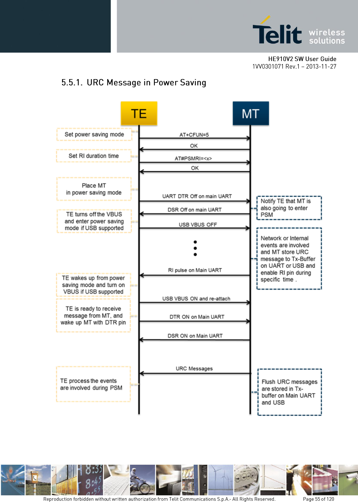
Figure 4.1 the flow chart for URC message in power saving mode

Above Figure 4.1 illustrates the action flow to get URC messages are invoked while both
DTE and modem in sleep mode. UE910 V2 FAMILY AND UC864-E V2 offers below serial
ports, which have their own the limitation for flow control methods.
Table 4.1 the flow control capability for each serial interface
Flow Control Method
Hardware Flow
Software Flow
Main UART
Support
Support
Telit USB Modem
Support(only for data mode)
Not Support
Telit USB Auxiliary
Not Support
Not Support
UE910 V2 FAMILY AND UC864-E V2 keeps the URC messages are listed in Table 4.1 and
enabled by AT command in power saving mode.
Table 4.2 URC message List
URC Message
Enable/Disable AT Command
RING
Not Support , Always enabled
NO CARRIER
Not Support , Always enabled
CONNECT
Not Support , Always enabled
+CIEV
+CIND
+CREG
+CREG
+CGREG
+CGREG
+CMTI,+CMT,+CBM,+CDS,+CDSI
+CNMI
+CCWA
+CCWA
#TEMPMEAS
#TEMPMON
#MWI
#MWI
#GSMAS
#GSMAD
+SRING
Not Support , Always enabled
+CRING
+CRC
+CLIP
+CLIP
+CUSD
+CUSD
+CCM
+CAOC
+CSSI,+CSSU
+CSSN
+CALA
+CALA
#QSS
#QSS
#ECAM
#ECAM
UE910 V2 FAMILY AND UC864-E V2 keeps the URC messages are listed in Table 4.1 and
enabled by AT command in power saving mode.
Table 3.1-3 VBUS Control System
Product
VBUS Master
UE910 V2 FAMILY
AND UC864-E V2
DTE ( must turn off VBUS when entering to sleep mode and turn on
VBUS when waking up from sleep mode )
Note: DTE can get URC message using only Main UART in power saving mode. If Main
UART is reserved for data communication, it’s impossible to get URC messages are invoked
during power saving mode. UE910 V2 FAMILY AND UC864-E V2 can’t keep URC
messages larger than 8K bytes, when hardware flow control is activated by
RTS(AT#CFLO=1). We recommend that DTE get the URC message as soon as RI signal is
guaranteed on Main UART.
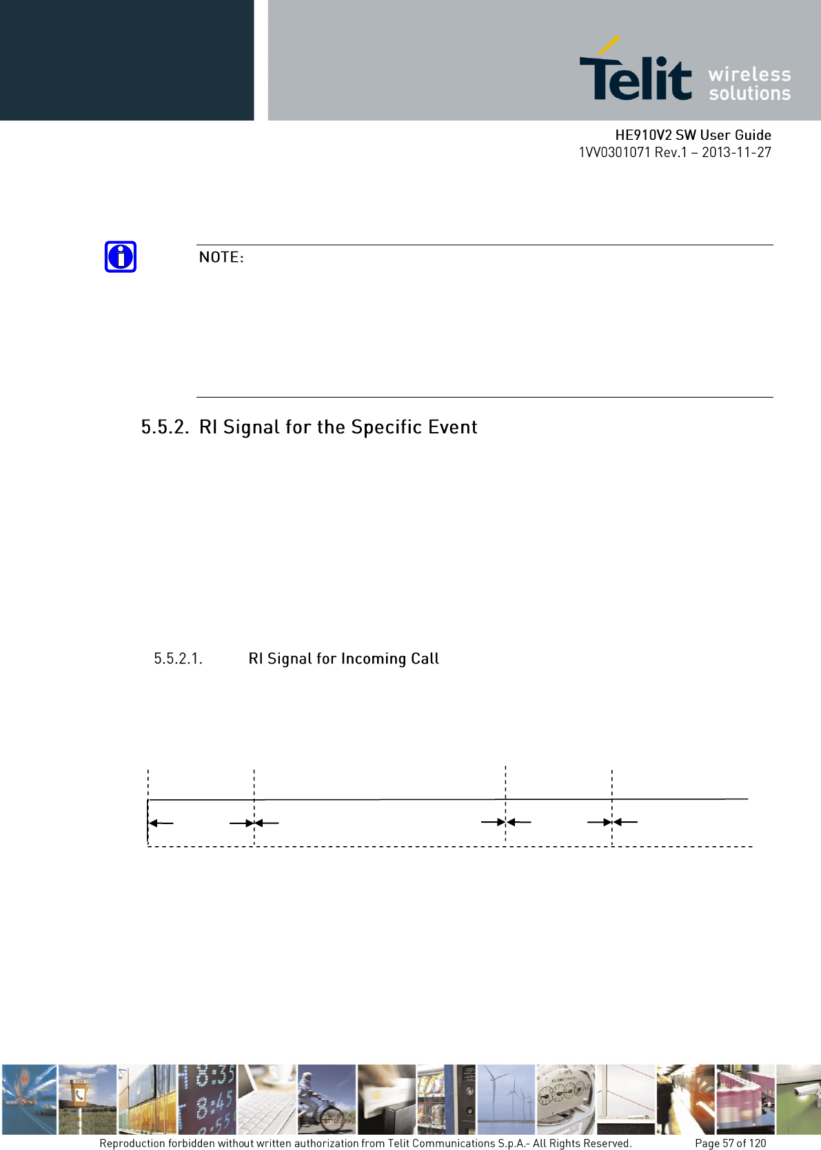
UE910 V2 FAMILY AND UC864-E V2 provides the option to allow DTE to enter sleep
mode with the maintenance of data connection.
Above Figure 3.2-1 illustrates the action flow to achieve this purpose.
This option is applied only to PS Data Service. (Not support for the service such as CS Data
and FAX).
We recommend that DTE must wake up from sleep mode and get incoming data as soon as
possible. Network operators have their own inactivation timer for data transmission.
If DTE doesn’t wake up from sleep mode even though RI signal is activated, the data
connection may be disconnected by network.
DTE can wake up from sleep mode by monitoring RI pin, while it‘s in sleep mode. UE910 V2
FAMILY AND UC864-E V2 provides different RI signal type to DTE, according to the
specific event.
This paragraph deals with the following items:
RI Signal for incoming call
RI Signal for incoming SMS
RI Signal for socket listen during server mode
RI Signal for URC message and incoming data during power saving mode
RI signal for incoming call has different signal in accordance with the value of \R and RING
message is sent to DTE the instance RI signal is going to is activated, periodically.
In case the value of \R is 0 or 1, RI signal and RING message like as figure 4.3 is generated.
In case the value of \R is 2, RI signal and RING message is generated like as Figure 4.4.
1000ms
RING
4000ms
RING
1000ms
4000ms
Figure 4.3 RI signal for \R0 or \R1
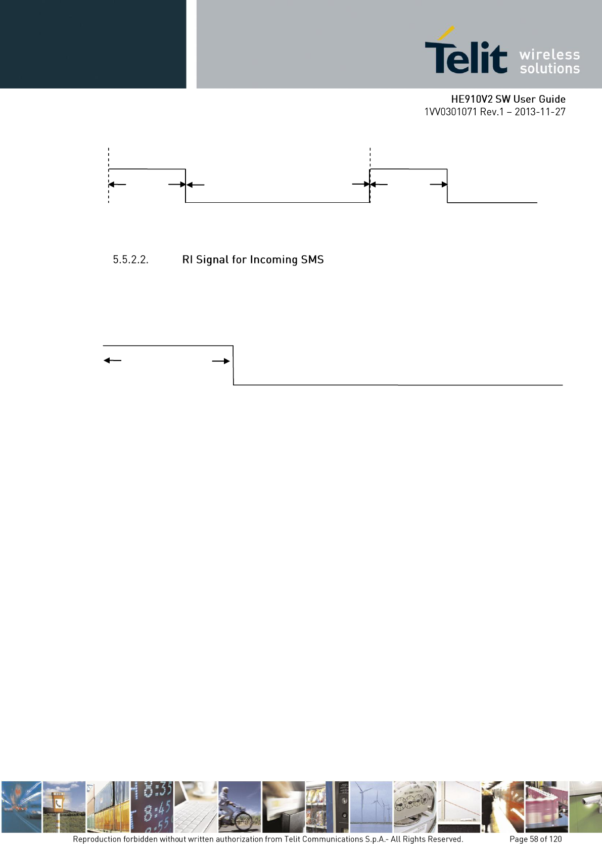
RI signal for incoming SMS has two types in accordance with the value of +CNMI or
#E2SMSRI. In case +CNMI=3,1, the negative going pulse like as figure 4.5 is generated, one
time.
In case #E2SMSRI = <x>, the negative going pulse like as figure 4.6 is generated, one time.
4000ms
1000ms
RING
1000ms
RING
4000ms
Figure 4.4 RI signal for \R2
1000 ms
Figure 4.5 RI Signal for +CNMI=3,1
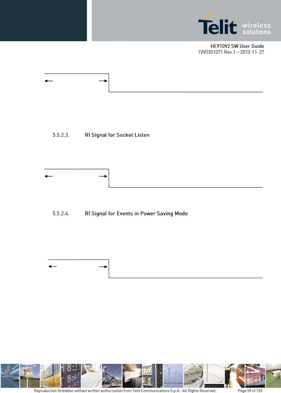
Note: In case both +CNMI=3,1 and #E2SMSRI=<x> is issued, RI signal behavior by
#E2SMSRI is ignored by +CNMI
RI Signal is generated, when modem receive TCP connection request from remote client
during socket server mode. This signal is the negative going pulse and is generated, one time.
RI Signal for URC message and incoming data is generated, only when modem is in power
saving mode. #PSMRI must be set as the value is not 0 and AT#CFLO=1 must be issued.
DTE issue AT+CFUN=5 and Drop DTR pin on main UART to place modem in the power
saving mode.
Note: if RI signal for Incoming Call, SMS, Socket Listen and #PSMRI are generated at the
same time in power saving mode, RI signal for #PSMRI will be ignored.
#E2SMSRI value
(50 ~11500 ms)
Figure 4.6 RI Signal for #E2SMSRI
#E2SLRI value
(50 ~11500 ms)
Figure 4.7 RI Signal for #E2SLRI
#PSMRI value
(50 ~11500 ms)
Figure 4.8 RI Signal for #PSMRI
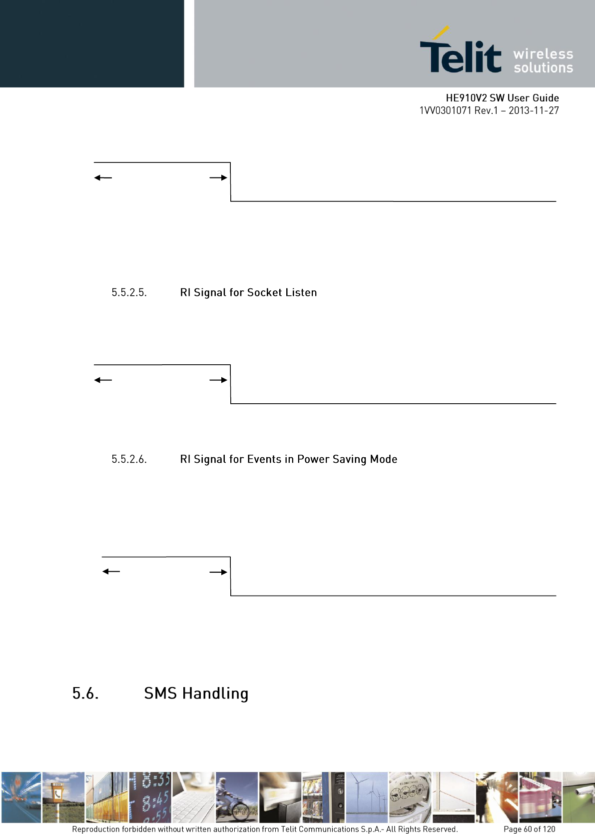
Note: In case both +CNMI=3,1 and #E2SMSRI=<x> is issued, RI signal behavior by
#E2SMSRI is ignored by +CNMI
RI Signal is generated, when modem receive TCP connection request from remote client
during socket server mode. This signal is the negative going pulse and is generated, one time.
RI Signal for URC message and incoming data is generated, only when modem is in power
saving mode. #PSMRI must be set as the value is not 0 and AT#CFLO=1 must be issued.
DTE issue AT+CFUN=5 and Drop DTR pin on main UART to place modem in the power
saving mode.
Note: if RI signal for Incoming Call, SMS, Socket Listen and #PSMRI are generated at the
same time in power saving mode, RI signal for #PSMRI will be ignored.
The Telit HE910V2 family supports the Short Message Service, it is possible to store, delete,
write, send and receive a SMS, which is a short text message up to 160 characters long.
#E2SMSRI value
(50 ~11500 ms)
Figure 4.6 RI Signal for #E2SMSRI
#E2SLRI value
(50 ~11500 ms)
Figure 4.7 RI Signal for #E2SLRI
#PSMRI value
(50 ~11500 ms)
Figure 4.8 RI Signal for #PSMRI
Before accessing the Short Message Service, the device has to be properly set up.
The HE910V2 family supports SMS in two different formats:
PDU
Text
The difference is that in the PDU mode the device returns and receives SMS encoded in the
format ready to be sent to the network; in TEXT mode the device converts automatically the
read PDU into text and vice versa. By using TEXT mode, the PDU data encoding knowledge
is not needed and operations are easier. For this reason, we are using the TEXT mode to
explain how to operate with SMS. If you are familiar with PDU encoding then you can
operate with PDU by selecting that format and using appropriate command syntax.
Send command AT+CMGF=<mode><cr>
Where:
<mode> is the SMS format type:
0 - PDU
1 - Text
wait for response OK
This setting is stored and remains until the device is turned off. Hence, there is no need to
issue it more than one time. For TEXT mode use <mode>=1.
For example:
1- Let us assume you want to set TEXT format for the SMS:
command
AT+CMGF=1<cr>
response:
OK
The SMS are sent by the HE910V2 family to a service center (SMSC) where the message is
dispatched towards its final destination or is kept until the delivery is possible. To ensure a
correct behavior of this service the number of the service center must be the one your network
operator supports.
To check which number is stored as the SMSC:
send command AT+CSCA?<cr>
wait for response in the format: +CSCA: <number>,<type>
OK
where:
<number> is the SMSC number
<type> is the SMSC number type:
145 - international numbering scheme (number begins with "+")
129 - national numbering scheme
This setting remains stored in the SIM card until it is changed or deleted, so this operation
may be done only once if the SIM Card is not changed. The setting is maintained even after
power down.
For example:
1- Let us assume you want to check your SMSC number:
command
AT+CSCA? <cr>
response:
+CSCA: +393359609600
OK
If your previously check for SMSC returned an empty field:
+CSCA: ,129
Or if the SMSC number stored does not correspond to the desired one, then the new number
has to be stored. In this way, the previously stored number will be overwritten.
send command AT+CSCA=<number>,<type><cr>
where:
<number> is the desired SMSC number
<type> is the SMSC number type:
145 - international numbering scheme (number begins with "+")
129 - national numbering scheme
wait for OK
For example:
1- Let us assume your desired SMSC number is +39335123456 (stored in international
format):
command
AT+CSCA=+39335123456,145<cr>
response:
OK
When the device receives a new message an unsolicited indication is generated, this
indication may be sent to the DTE, buffered if the DTE is busy (for example during a data
call) or discarded.
To set the desired behavior:
send command
AT+CNMI=<mode>,<mt>,<bm>,<ds>,<bfr><cr>
where:
Set command selects the behaviour of the device on how the receiving of new messages from
the network is indicated to the DTE.
Parameter:
<mode> - unsolicited result codes buffering option
0 - Buffer unsolicited result codes in the TA. If TA result code buffer is full, indications can
be buffered in some other place or the oldest indications may be discarded and replaced with
the new received indications.
1 - Discard indication and reject new received message unsolicited result codes when TA-TE
link is reserved, otherwise forward them directly to the TE.
2 - Buffer unsolicited result codes in the TA in case the DTE is busy and flush them to the TE
after reservation. Otherwise forward them directly to the TE.
3 - if <mt> is set to 1 an indication via 100 ms break is issued when a SMS is received while
the module is in GPRS online mode. It enables the hardware ring line for 1 s. too.
<mt> - result code indication reporting for SMS-DELIVER
0 - No SMS-DELIVER indications are routed to the TE.
1 - If SMS-DELIVER is stored into ME/TA, indication of the memory location is routed to
the TE using the following unsolicited result code:
+CMTI: <memr>,<index>
where:
<memr> - memory storage where the new message is stored
"SM"
"ME"
"SR"

<index> - location on the memory where SM is stored.
2 - SMS-DELIVERs (except class 2 messages and messages in the message waiting
indication group) are routed directly to the TE using the following unsolicited result code:
(PDU Mode)
+CMT: <alpha>,<length><CR><LF><pdu>
where:
<alpha> - alphanumeric representation of originator/destination number corresponding to the
entry found in MT phonebook
<length> - PDU length
<pdu> - PDU message
(TEXT Mode)
+CMT:<oa>,<alpha>,<scts>[,<tooa>,<fo>,<pid>,<dcs>,
<sca>,<tosca>,<length>]<CR><LF><data> (the information written in italics will be
present depending on +CSDH last setting)
where:
<oa> - originating address, string type converted in the currently selected character set (see
+CSCS)
<alpha> - alphanumeric representation of <oa>; used character set must be the one selected
with either command +CSCS.
<scts> - arrival time of the message to the SC
<tooa>, <tosca> - type of number <oa> or <sca>:
129 - number in national format
145 - number in international format (contains the "+")
<fo> - first octet of 3gpp 03.40/23.040
<pid> - Protocol Identifier
<dcs> - Data Coding Scheme
<sca> - Service Centre address, string type, converted in the currently selected character set
(see +CSCS)
<length> - text length
<data> - TP-User-Data
Class 2 messages and messages in the message waiting indication group (stored message)
result in indication as defined in <mt>=1.
3 - Class 3 SMS-DELIVERs are routed directly to TE using unsolicited result codes defined
in <mt>=2. Messages of other data coding schemes result in indication as defined in <mt>=1.
<bm> - broadcast reporting option
0 - Cell Broadcast Messages are not sent to the DTE

2 - New Cell Broadcast Messages are sent to the DTE with the unsolicited result code:
(PDU Mode)
+CBM: <length><CR><LF><PDU>
where:
<length> - PDU length
<PDU> - message PDU
(TEXT Mode)
+CBM:<sn>,<mid>,<dcs>,<pag>,<pags><CR><LF><data>
where:
<sn> - message serial number
<mid> - message ID
<dcs> - Data Coding Scheme
<pag> - page number
<pags> - total number of pages of the message
<data> - CBM Content of Message
<ds> - SMS-STATUS-REPORTs reporting option
0 - status report receiving is not reported to the DTE
1 - the status report is sent to the DTE with the following unsolicited result code:
(PDU Mode)
+CDS: <length><CR><LF><PDU>
where:
<length> - PDU length
<PDU> - message PDU
(TEXT Mode)
+CDS: <fo>,<mr>,<ra>,<tora>,<scts>,<dt>,<st>
where:
<fo> - first octet of the message PDU
<mr> - message reference number
<ra> - recipient address, string type, represented in the currently selected character set (see
+CSCS)
<tora> - type of number <ra>
<scts> - arrival time of the message to the SC
<dt> - sending time of the message
<st> - message status as coded in the PDU
2 - if a status report is stored, then the following unsolicited result code is sent:
+CDSI: <memr>,<index>
where:
<memr> - memory storage where the new message is stored
"SR"
<index> - location on the memory where SM is stored
<bfr> - buffered result codes handling method:
0 - TA buffer of unsolicited result codes defined within this command is flushed to the TE
when <mode>=1..3 is entered (OK response must be given before flushing the codes)
1 - TA buffer of unsolicited result codes defined within this command is cleared when
<mode>=1..3 is entered.
NOTE: Issuing AT+CNMI<CR> is the same as issuing the Read command.
NOTE: Issuing AT+CNMI=<CR> is the same as issuing the command AT+CNMI=0<CR>.
wait for OK
In this command description the values that are always 0 are parameter reserved for future use,
in the current software revision the only value supported is 0.
For example:
1- Let us assume you want to eliminate all the unsolicited codes that may be sent when
receiving SMS & Status Report:
Command
AT+CNMI= 0,0,0,0,0<cr>
Response:
OK
For example about a new message indication:
1- Let us assume you receive a new SMS delivery (AT+CNMI=1,1,0,0,0) and this new
message is stored on the SIM "SM" storage at the location number 7; the unsolicited code you
will receive (if code is enabled) is:
Unsolicited code:
+CMTI: "SM",7
2- Let us assume you receive a new SMS Status Report delivery (AT+CNMI=1,0,0,2,0) and
this new message is stored on the SIM "SR" storage at the location number 8; the unsolicited
code you will receive is:
Unsolicited code:
+CDSI: "SR",8
When the device is set to operate with Text SMS not with PDU, the SMS parameters that
usually reside on the header of the PDU must be set apart with the command +CSMP.
The parameters to be set are:
Message Format
Validity Period
Protocol Identifier
Data Coding Scheme
The meaning and format of the parameters is:
Message format, like defined for the first octet of message according to GSM 3.40/23.040:
The format is an 8-bit parameter divided into 6 fields and then reported as an integer:
b7
b6
b5
b4
b3
b2
b1
b0
RP
UDHI
SRR
VPF
RD
MTI
Where
MTI message type parameter:
0 1 - SMS Submit
0 1 - SMS DELIVER
RD rejects duplicates parameter
0 – do not reject duplicates SMS in SC
1 - reject duplicates on SC
VPF validity period format
0 0 - Validity period NOT present
1 0 - VP integer represented (relative)
1 1 - VP semi octet represented (absolute)
0 1 - reserved
SRR status report request
0 - status report not requested
1 - status report requested
UDHI user data Header Information
0 - No Header on PDU
1 - Header present on PDU
RP reply path
0 - RP not set

1 - RP set
Validity Period numerical if in relative format or string if in absolute format
This parameter represents the validity period for the SMS after which the message must be
disregarded instead of being delivered.
If in relative format (see VPF parameter) it is an integer:
0 to 143 - corresponding to (VP + 1) x 5 minutes
144 to 167 - corresponding to 12 hours + ((VP -143) x 30 minutes)
168 to 196 - corresponding to (VP - 166) x 1 day
197 to 255 - corresponding to (VP - 192) x 1 week
If in absolute format it is a string in the format:
"gg/MM/YY,hh:mm:ss±tz"
where
gg day of expiration (2 characters)
MM month of expiration (2 characters)
YY year of expiration (2 characters)
hh hour of expiration (2 characters)
mm minute of expiration (2 characters)
ss second of expiration (2 characters)
± sign of the time zone (+ or -)
tz time zone (2 characters)
Protocol Identifier in numerical format: This parameter identifies the protocol used by the
receiver entity and informs the SC that the conversion from SMS to that protocol must be
done while delivering the message.
Protocol ID
Conversion towards
0
Implicit (default)
33
telex (or teletex reduced to telex format)
34
group 3 telefax
35
group 4 telefax
36
voice telephone (i.e. conversion to speech)
37
ERMES (European Radio Messaging
System)
38
National Paging system (known to the SC)
39
Videotex (T.100/T.101)
40
teletex, carrier unspecified
41
teletex, in PSPDN
42
teletex, in CSPDN
43
teletex, in analog PSTN
44
teletex, in digital ISDN

45
UCI (Universal Computer Interface, ETSI
DE/PS 3 01-3)
46-47
(reserved, 2 combinations)
48
a message handling facility (known to the
SC)
49
any public X.400-based message handling
system
50
Internet Electronic Mail
51-55
(reserved, 5 combinations)
56-62
values specific to each SC, usage based on
mutual agreement between the SME and
the SC (7 combinations available for each
SC)
63
A GSM mobile station. The SC converts
the SM from the received TP-Data-
Coding-Scheme to any data coding scheme
supported by that MS (e.g. the default).
64
Short Message Type 0
65
Replace Short Message Type 1
66
Replace Short Message Type 2
67
Replace Short Message Type 3
68
Replace Short Message Type 4
69
Replace Short Message Type 5
70
Replace Short Message Type 6
71
Replace Short Message Type 7
72..94
Reserved
95
Return Call Message
96..126
Reserved
127
SIM Data download
Data coding Scheme as defined by GSM 3.38 - in numerical format The DCS is an 8-bit
parameter reported as an integer, the default value is 0, otherwise for simplicity, we report
only the most useful DCS, for further Schemes refer to GSM 3.38
B7
B6
b5
b4
b3
b2
b1
b0
1
1
1
1
0
Alphabet
Class
where
Alphabet
0 - default Alphabet
1 - 8 bit
Class
0 0 - Class 0
0 1 - Class 1
1 0 - Class 2
1 1 - Class 3

The default value for DCS = 0 represents the default SMS sent by a mobile. If you do not
need any particular data coding scheme use DCS=0.
Not all the DCS combinations described in the 3gpp 3.38/23.038 are supported, both by the
network and by the Telit HE910V2. Some features may be not implemented at network level
or at device level, resulting in a +CME ERROR: 3 (operation not allowed) result code. If this
happens then use a different DCS.
send command AT+CSMP=<fo>,<vp>,<pid>,<dcs><cr>
where:
<fo>: Message format
<vp>: Validity Period
<pid>: Protocol Identifier
<dcs>: Data coding Scheme
wait for OK
For example:
1- Let us assume you want to set the SMS parameters to the values:
Message Format:
SMS submit
do not reject duplicates
VP Format integer (relative)
status report not requested
No Header on PDU
Reply path not set
Hence, the message format is the binary number 00010001 corresponding to the integer 17.
Validity period 24 hours corresponding to an integer value 167. 12 hours + ((167
-143) x 30 min) = 24 hours
Protocol ID implicit (SMS sent to a mobile terminal) corresponding to a value 0.
DCS default value 0.
command
AT+CSMP= 17,167,0,0
response:
OK
2- Let us assume you want to set the SMS parameters to the values:
Message Format:
SMS submit
do not reject duplicates
VP Format semi octet (absolute)
status report requested
No Header on PDU
Reply path not set
Hence, the message format is the binary number 00111001 corresponding to the integer 57.
Validity period format is absolute, hence it represents the expiration date of the message and
the desired expiration date is for example 29/06/02 at 02:20 in the time zone of Italy (+1).
"29/06/02,02:20:00+1"
Protocol ID implicit (SMS sent to a mobile terminal) corresponding to a value 0.
Data Coding Scheme:
Default Alphabet
Class 0 (e.g. immediate display SMS)
Corresponding to the binary number 11110000 corresponding to the integer 240.
command
AT+CSMP= 57,29/06/02,02:20:00+1,0,240
response:
OK
There are various types of storage where the SMS can be stored, the Telit HE910V2 family
provides two different storage:
"ME" - mobile equipment memory
"SM" - SIM Card memory
"SR" – Status report
The SMS are usually stored (this is true for both the originated and the received SMS) in the
SM/ME storage.
The HE910V2 family allows the user to select a different storage for the read-delete, write-
send, and reception-saving SMS operations.
send command AT+CPMS=<memr>,<memw>,<mems><cr>
where:
<memr>: memory storage for Read and Delete commands
- "SM"
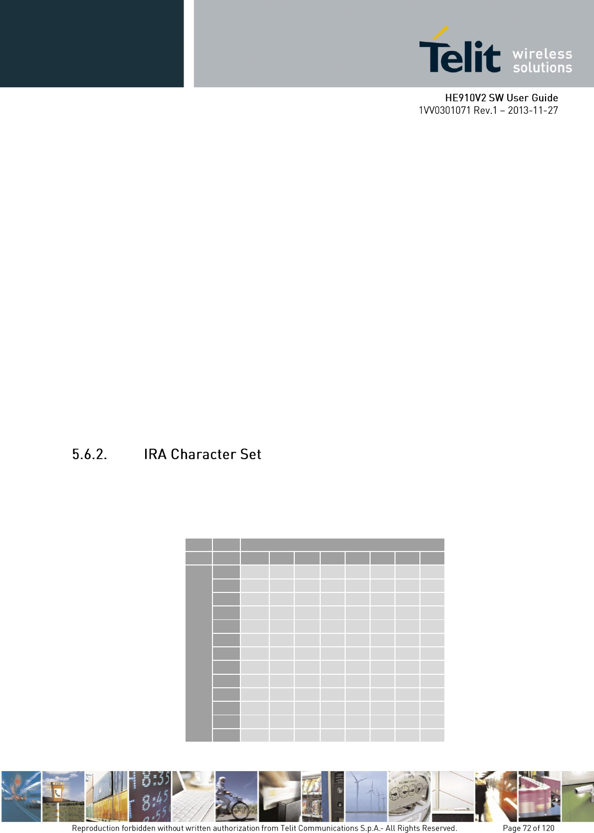
- "ME"
- "SR"
<memw>: memory storage for Write and Send commands
<mems>: memory storage for new incoming message saving
wait for response in the format:
+CPMS:<usedr>,<totalr>,<usedw>,<totalw>,<useds>,<totals>
OK
where
<usedr> - number of SMS stored into <memr>
<totalr> - max number of SMS that <memr> can contain
<usedw> - number of SMS stored into <memw>
<totalw> - max number of SMS that <memw> can contain
<useds> - number of SMS stored into <mems>
<totals> - max number of SMS that <mems> can contain
From this response you can check if the selected storage has room for new SMSs, the free
positions in the storage X (where X can be r,w,s) are <totalX> -<usedX>.
The character set used in SMS text mode is the IRA. This set defines each char as a 7-bit
value, hence from 0x00 to 0x7F. The table below reports all the chars supported and their
hexadecimal code. To obtain the code for a char in the table remember that in the row it is
reported the least significant nibble (4 bits) and in the column the most significant nibble. The
empty cells correspond to reserved combinations.
Most Significant Nibble
0x
1x
2x
3x
4x
5x
6x
7x
Least Significant Nibble
x0
SP1
0
@
P
p
x1
!
1
A
Q
a
q
x2
"
2
B
R
b
r
x3
#
3
C
S
c
s
x4
$
4
D
T
d
t
x5
%
5
E
U
e
u
x6
&
6
F
V
f
v
x7
'
7
G
W
g
w
x8
(
8
H
X
h
x
x9
)
9
I
Y
i
y
xA
LF2
*
:
J
Z
j
z
xB
+
;
K
k
xC
,
<
L
l
xD
CR3
-
=
M
m
xE
.
>
N
n
xF
/
?
O
£
o
1 - SP stands for space character
2 - LF stands for Line Feed character
3 - CR stands for Carriage Return character
For example:
1- Let us assume you want to find the IRA code for the character '&':
From the table you find:
most significant Nibble: 2
least significant Nibble: 6
Hence the IRA code for the '&' character is the hexadecimal 0x26.
2- Let us assume you have the IRA code 0x6B and you want to find the corresponding
character:
From the table you find at the position
most significant Nibble: 6
least significant Nibble: B
Hence, the character corresponding to the 0x6B IRA code is 'k'.
With the command AT+CSCS is possible to select the character set; the available types are:
“IRA” - ITU-T.50
”8859-1” - ISO 8859 Latin 1
”PCCP437” - PC character set Code Page 437.
”UCS2” - 16-bit universal multiple-octet coded character set (ISO/IEC10646)
Please refer to the AT command specification for the full command description.
A new SMS can be written in the selected storage <memw> (in the current SW version only
"SM" is supported) and then can be sent to the desired destination.
To write the new SMS:
send command AT+CMGW="<da>"<cr>
where:
<da>: destination address
wait for prompt ">"
send SMS text (MAX 160 characters)
end command with CTRL-Z character (0x1A hexadecimal) or abort command
with ESC character (0x1B hexadecimal)
wait for response:
Response
Reason
Action
+CMGW: <index>
OK
Message has been successfully
written in position number
<index>
proceed ahead
ERROR
some error occurred
Enable the extended error codes
report (see par. 4.4.2.1) and retry.
+CMS ERROR: 330
SMSC address unknown
Insert SMSC address (see par.
5.6.1.3)
+CMS ERROR: 322
Memory Full
Memory is full, hence delete some
records and retry.
if command is aborted with ESC character, then only the OK result code is returned.
For example:
1- Let us assume you want to write a new SMS to the storage and the destination address is
the number +39338123456789. We suppose you already have set up the device for text SMS
mode as described on the previous paragraphs:
command
AT+CMGW="+39338123456789"
response:
>
now you can insert the message text in IRA format (note that the IRA format and ASCII
format coincide for the alphabet characters but not for the other).
…here will be inserted the SMS message text…
conclude text with the character CTRL-Z
response:
+CMGW: 3
OK
In this case, the new SMS was successfully written to the location index 3 of the selected
write memory.
An already written SMS can be sent from the selected storage <memw>.
To send the written SMS its location index is needed:
send command AT+CMSS=<index><cr>
where:
<index>: SMS location index
wait for response:
Response
Reason
Action
+CMSS: <mr>
OK
Message has been successfully
sent. <mr> represents the message
reference number.
proceed ahead
ERROR
some error occurred
Enable the extended error codes
report (see par. 4.4.2.1) and retry.
+CMS ERROR: 330
SMSC address unknown
Insert SMSC address (see par.
5.6.1.3)
+CMS ERROR: 41
"Temporary Failure", may be that
the device is not registered on any
network
Check for signal strength and
network registration
+CMS ERROR: 331
No network service
Check for signal strength and
network registration
+CMS ERROR: 1
Unassigned number
The destination address number
does not exist. Check it and repeat
command.
+CMS ERROR: 42
network congestion
Retry later
+CMS ERROR: 96
Mandatory information missing
Check for destination address in
the SMS, overwrite it and retry.
For example:
1- Let us assume you want to send a SMS that was written to the storage index position
number 3. We suppose you already have set up the device for text SMS mode as described on
the previous paragraphs:
command
AT+CMSS=3
response:
+CMSS: 1
OK
In this case, the SMS was successfully sent to the destination and its network message
reference number is 1.
A new SMS can be sent directly to the network without storing it.
send command AT+CMGS="<da>"<cr>
where:

<da>: destination address
wait for prompt ">"
send SMS text (MAX 160 characters)
end command with CTRL-Z character (0x1A hexadecimal) or abort command
with ESC character (0x1B hexadecimal)
wait for response:
Response
Reason
Action
+CMGS: <mr>
OK
Message has been successfully
sent. <mr> represents the message
reference number.
proceed ahead
ERROR
some error occurred
Enable the extended error codes
report (see par. 4.4.2.1) and retry.
+CMS ERROR: 330
SMSC address unknown
Insert SMSC address (see par.
5.6.1.3)
+CMS ERROR: 41
"Temporary Failure", may be that
the device is not registered on any
network
Check for signal strength and
network registration
+CMS ERROR: 331
No network service
Check for signal strength and
network registration
+CMS ERROR: 1
Unassigned number
The destination address number
does not exist. Check it and repeat
command.
+CMS ERROR: 42
network congestion
Retry later
+CMS ERROR: 96
Mandatory information missing
Check for destination address in
the SMS, overwrite it and retry.
OK
command aborted by user
you issued a ESC char
For example:
1- Let us assume you want to directly send a new SMS to the destination address number
+39338123456789. We suppose you already have set up the device for text SMS mode as
described on the previous paragraphs:
command
AT+CMGS="+39338123456789"
response:
>
now you can insert the message text in IRA format (note that the IRA format and ASCII
format coincide for the alphabet characters but not for the other).
…here will be inserted the SMS message text to be sent…
conclude text with the character CTRL-Z
response:
+CMGS: 4
OK
In this case, the new SMS was successfully sent to the SC and its network reference number
is 4.
Do not confuse message reference with message index position, the first indicates the network
reference for identifying the sent message (the eventually requested status report will have the
same reference) while the second indicates the position where the message has eventually
been stored in the memory.
An SMS can be sent by means of the GPRS service . It is worth to remind that not all
Network Operators support this features.
AT+CGSMS=2
Examples
Send the SMS message to the module itself, not store it before transmitting and use the GPRS
service
AT#SELINT=2 Select AT command interface style
OK
AT+CGSMS=2 Select the GPRS service
OK
Check if the module is attached to GPRS service
AT+CGATT?
+CGATT: 1
OK
Select Text Mode.
AT+CMGF=1
OK
Select how the new received message event is indicated by the DCE to the DTE.
AT+CNMI=1,1,0,0,0
OK
Send the message to the module itself.
AT+CMGS="+386X18X19X4"
> SEND THE SMS BY MEANS OF THE GPRS SERVICE TO ITSELF (close the
message with Ctrl Z)
+CMGS: 14
OK
The SMS is received by the module itself, the following unsolicited indication is showed on
DTE:
+CMTI: "SM",11
AT+CPMS="SM"
+CPMS: 11,50,11,50,11,50
OK
Use unsolicited indication parameter to read the SMS for the first time.
An already written/received SMS can be deleted from the selected storage.
To delete the SMS its location index is needed:
send command AT+CMGD=<index>[,<delflag>]<cr>
where:
<index>: SMS location index, if <delflag> = 0
Test command shows the valid memory locations and optionally the supported values of
<delflag>.
<delflag>: an integer indicating multiple message deletion request as follows:
0 (or omitted) Delete the message specified in <index>
1 Delete all read messages from preferred message storage, leaving unread messages
and stored mobile originated messages (whether sent or not) untouched
2 Delete all read messages from preferred message storage and sent mobile originated
messages, leaving unread messages and unsent mobile originated messages untouched
3 Delete all read messages from preferred message storage, sent and unsent mobile
originated messages leaving unread messages untouched.
4 Delete all messages from preferred message storage including unread messages.
wait for response:
Response
Reason
Action
OK
Message has been successfully
deleted.
proceed ahead
ERROR
some error occurred
Enable the extended error codes
report (see par. 4.4.2.1) and retry.
+CMS ERROR: 321
Invalid memory index
e.g. the given record was already
empty
Check the <index> number and
retry.
For example:
1- Let us assume you want to delete a previously written SMS that was written to the storage
index position number 3. We suppose you already have set up the device for text SMS mode
as described on the previous paragraphs:
command
AT+CMGD=3
response:
OK
In this case, the SMS was successfully deleted.
2- Let us assume you want to delete a received SMS that was stored to the index position
number 7:
command
AT+CMGD=7
response:
OK
A new SMS can be read with the command
send command AT+CMGR=<index><cr>
where:
<index>: SMS location index
wait for response in the format:
Output format for received messages (the information written in italics will be present
depending on +CSDH last setting):
+CMGR: <stat>,<oa>,<alpha>,<scts>[,<tooa>,<fo>,<pid>,
<dcs>,<sca>,<tosca>,<length>]<CR><LF><data>
Output format for sent messages:
+CMGR: <stat>,<da>,<alpha>[,<toda>,<fo>,<pid>,<dcs>,,
<sca>,<tosca>,<length>]<CR><LF><data>
Output format for message delivery confirm:
+CMGR: <stat>,<fo>,<mr>,,,<scts>,<dt>,<st>
where:
<stat> - status of the message
"REC UNREAD" - new received message unread
"REC READ" - received message read
"STO UNSENT" - message stored not yet sent
"STO SENT" - message stored already sent
<fo> - first octet of the message PDU

<mr> - message reference number
<scts> - arrival time of the message to the SC
<dt> - sending time of the message
<st> - message status as coded in the PDU
<pid> - Protocol Identifier
<dcs> - Data Coding Scheme
<oa> - Originator address, string type represented in the currently selected character set (see
+CSCS)
<da> - Destination address, string type represented in the currently selected character set (see
+CSCS)
<alpha> - string type alphanumeric representation of <da> or <oa>, corresponding to an
entry found in the phonebook; used character set is the one selected with command +CSCS.
NB: this optional field is currently not supported.
<sca> - Service Centre number
<tooa>,<toda >,<tosca> - type of number <oa>,<da>,<sca>
129 - number in national format
145 - number in international format (contains the "+")
<length> - text length
<data> - TP-User_data
If <dcs> indicates that GSM03.38 default alphabet is used , each character of GSM alphabet
will be converted into current TE character set (see +CSCS)
If <dcs> indicates that 8-bit or UCS2 data coding scheme is used, each 8-bit octet will be
converted into two IRA character long hexadecimal numbers (e.g. octet 0x2A will be
converted as two characters 0x32 0x41)
Note: in both cases if status of the message is 'received unread', status in the storage changes
to 'received read'. An error result code is sent on empty record <index>.
For example:
1- Let us assume you want to read the SMS that is stored at the position index 4. We suppose
you already have set up the device for text SMS mode as described on the previous
paragraphs:
Command
AT+CMGR=4
Response:
+CMGR: "STO UNSENT","+393351234565"
Telit Test Message for Text Mode SMS.
OK
In this case the SMS was successfully read, the text contained was:
"Telit Test Message for Text Mode SMS."
The message was written to the storage by user (STO) but still not sent (UNSENT) to the
destination address with the number +393351234565
2- Let us assume you want now to read the SMS that is stored at the position index 5:
Command
AT+CMGR=5
Response:
+CMGR: "REC UNREAD","+393381234567890", ,"29/06/01,12:30:04+01"
Telit Test Message for Text Mode SMS RECEIVING.
OK
In this case the SMS was successfully read, the text contained was:
"Telit Test Message for Text Mode SMS RECEIVING."
The message was received (REC) from the number +393381234567890 at 12:30:04 the day
29/06/01 in the European time zone +1. After this read command the message at index 5
becomes REC READ.
The SMS can be grouped into 5 different groups depending on their status:
REC UNREAD received messages still not read
REC READ received messages already read
STO UNSENT written messages not yet sent
STO SENT written messages already sent
ALL all types of messages
It is possible to have the list of all the messages in one group:
send command AT+CMGL=<stat><cr>
Where:
<stat> - status group of the message
"REC UNREAD" - new message
"REC READ" - read message
"STO UNSENT" - stored message not yet sent
"STO SENT" - stored message already sent
"ALL" - all messages
wait for response in the format:
For every message in the group:
+CMGL: <index>,<stat>,<oa/da> [,,,<tooa/toda>,<length>]
<CR><LF><text>
where:
<index> - message index position on the storage
<stat> - status of the message
"REC UNREAD" - new message
"REC READ" - read message
"STO UNSENT" - stored message not yet sent
"STO SENT" - stored message already sent
<oa/da> - sender number/destination number
<tooa/toda> - type of number <oa/da>
145 - international number (contains "+" character)
129 - national number
<length> - length of the message text in characters
<text> - message text
Note: If status of the message is 'received unread', status in the storage changes to 'received
read'.
For example:
1- Let us assume you want to list all the SMS received read that are stored. We suppose you
already have set up the device for text SMS mode as described on the previous paragraphs:
command
AT+CMGL="REC READ"
response:
+CMGL: 5, "REC READ","+393381234567890"
Telit Test Message for Text Mode SMS RECEIVING.
+CMGL: 8, "REC READ","+393381234567890"
Telit Second Test Message for Text Mode SMS RECEIVING.
OK
In this case the SMS group was successfully read, the messages Received UNREAD were
two in the position indexes 5 & 8. The optional parameters <tooa/toda> and <length> were
not shown.
GSM Standard specifies two different types of SMS:
SMS Point to Point (SMS/PP),
SMS Cell Broadcast (SMS/CB).

The first type can send a text message long up to 160 characters from a module to the another
(as stated on the previous paragraphs), the second type allows the Network to send, at the
same time, a message to all modules contained in the defined area including one or more
radio cells. The availability and the implementation of the Cell Broadcast Service are strictly
connected with the Network Operator of the subscriber.
Use the following AT command to enable the Cell Broadcast Service:
AT+CSCB=[<mode>[,<mids>[,<dcss>]]]
Example
Select Text Mode.
AT+CMGF=1
OK
Select the District service.
AT+CSCB=0,50,0
OK
Select how the new received message event is indicated by the DCE to the DTE.
AT+CNMI=2,0,2,0,0
OK
After a while the “District” broadcast message is displayed on the DTE.
+CBM: 24,50,1,1,1
TRIESTE
+CBM: 4120,50,2,1,1
TRIESTE
+CBM: 8216,50,1,1,1
TRIESTE
+CBM: 12312,50,2,1,1
TRIESTE
The following list of Services can be provided by the Network Operator, it is not mandatory:
<mids> Service name
000 Index
010 Flashes
020 Hospitals
022 Doctors
024 Pharmacy
030 Long Distant Road Reports
032 Local Road Reports
034 Taxis
040 Weather
050 District
052 Network Information
054 Operator Services
056 Directory Inquiries (national)
057 Directory Inquiries (international)
058 Customer Care (national)
059 Customer Care (international)
Use the following AT command to read concatenated SMSs:
AT#CMGLCONCINDEX
Example
Check the number of stored SMSs
AT+CPMS?
+CPMS: "SM",6,30,"SM",6,30,"SM",6,30
OK
6 SMSs are stored.
Check if concatenated SMSs are stored
AT#CMGLCONCINDEX
OK
No concatenated SMSs are stored
Set up Text Mode
AT+CMGF=1
OK
Set SMS parameters
AT+CSMP=17,167,0,242
OK
Store two concatenated SMSs (they are indicated with two colors):
AT+CMGW= "+3932X056Y6X8"
>12345678901234567890123456789012345678901234567890123456789012345678901234
567890123456789012345678901234567890123456789012345679012345678901234567890
123456789098765432109876543210
+CMGW: 8
OK
Check the number of SMSs stored on the “SM” storage type
AT+CPMS?
+CPMS: "SM",8,30,"SM",8,30,"SM",8,30
OK
Check the concatenated SMSs presence
AT#CMGLCONCINDEX
#CMGLCONCINDEX: 2,7,8
OK
2 SMSs are concatenated. Their storage positions are: 7, 8.
AT+CMGR=7
+CMGR: "STO UNSENT","01085718504",""
05000306020162B219AD66BBE172B0986C46ABD96EB81C2C269BD16AB61B2E078BC
966B49AED86CBC162B219AD66BBE172B0986C46ABD96EB81C2C269BD16AB61B2E
078BC966B49AED86CBC162B219AD66BBE172B0986C46ABD96EB81C2C269BD16AB
61B2E078BC966B49AED86CBC162B219AD66BBE56031D98C56B3DD7039584C36A3D
56C375C0E1693CD68
OK
AT+CMGR=8
+CMGR: "STO UNSENT","01085718504",""
0500030602026AB61B2E07CBE16EB61A6D268BC172B89BAD469BC96230
OK
The Telit HE910V2 family provides various General Purpose Input/output pins, these pins
can be configured via AT commands as Inputs, Outputs and two of them as "alternate
function".
The "alternate function" is supported by pins GPIO5, which can be configured to become a
RF Transmission monitor output pin that reflects the RF transmission activation, GPIO6,
which can be configured to become an alarm output pin that reflects the alarm status.
With these pins your application can control external hardware directly using the Telit
HE910V2 family pins, with little or even no hardware added.
Before using the GPIO pin, you must configure them to select their direction or alternate
function
When you set a GPIO as output, you must specify also the value that the pin output must take:
send command AT#GPIO=<pin>,<value>,1<cr>
where:
<pin> is the GPIO pin number at which the command applies:
1 - GPIO1 6 - GPIO6
2 - GPIO2 7 - GPIO7
3 - GPIO3 8 - GPIO8
4 - GPIO4 9 - GPIO9
5 - GPIO5 10 - GPIO10
<value> is the GPIO pin value that the pin will assume:
0 - LOW
1 - HIGH
wait for response OK
The #GPIO setting is not saved and will be lost on power off, so at start-up repeat pin
initialization commands. At start-up the setting for GPIO6 instead is maintained even after a
shutdown to permit alarm feature to work always.
For example:
1- Let us assume you want to set GPIO3 pin as Output and you want it to be in LOW status:
command
AT#GPIO=3,0,1<cr>
response:
OK
In this case, the GPIO3 pin was successfully put in output direction and its status has been set
to LOW.
When you set a GPIO as input, you must specify also a dummy value for the pin state:
send command AT#GPIO=<pin>,<dummy_value>,0<cr>
where:
<pin> is the GPIO pin number at which the command applies:
1 - GPIO1 6 - GPIO6
2 - GPIO2 7 - GPIO7
3 - GPIO3 8 - GPIO8
4 - GPIO4 9 - GPIO9
5 - GPIO5 10 - GPIO10
<value> is a dummy value can be either:
0 - dummy value
1 - dummy value
wait for response OK
The #GPIO setting for all GPIO except from GPIO6 is not saved and will be lost on power
off, so at start-up repeat pin initialization commands.
At start-up all the GPIOs except from GPIO6 are configured by default as INPUT, but the
setting for GPIO6 instead is maintained even after a shutdown to permit alarm feature to work
always.
For example:
1- Let us assume you want to set GPIO4 pin as Input:
command
AT#GPIO=4,0,0<cr>
response:
OK
In this case, the GPIO4 pin was successfully put in input direction.
After having set-up the GPIO pin direction you can query the input status of an INPUT pin or
set the output status of an OUTPUT pin.
To query for the pin status:
send command AT#GPIO=<pin>,2<cr>
where:
<pin> is the GPIO pin number at which the command applies:
1 - GPIO1 6 - GPIO6
2 - GPIO2 7 - GPIO7
3 - GPIO3 8 - GPIO8
4 - GPIO4 9 - GPIO9
5 - GPIO5 10 - GPIO10
wait for response in the format:
#GPIO: <dir>,<stat>
OK
where:

<dir> - GPIO<pin> direction setting
<stat> - status of the pin
0 - LOW
1 – HIGH
In case the GPIO pin direction is set to ALTERNATE FUNCTION (2), then the reported
<stat> has no meaning and must not kept as valid, but must be threaten as a dummy value.
The query reports depending on the pin direction:
- the read pin status in case the direction is input;
- the previously set pin status in case the direction is output.
In any case, you can know if the pin at the query moment is high or low and the pin direction.
For example:
1- Let us assume you want to query the GPIO3 pin for its status:
command
AT#GPIO=3,2<cr>
response:
#GPIO: 0,1
OK
In this case, the GPIO3 pin was set in input direction and its status has been measured to be
HIGH.
2- Let us assume you want to query the GPIO4 pin for its status:
command
AT#GPIO=4,2<cr>
response:
#GPIO: 1,0
OK
In this case, the GPIO4 pin was set in output direction and its status is LOW.
3- Let us assume you want to query the GPIO6 pin for its status:
command
AT#GPIO=6,2<cr>
response:
#GPIO: 2,0
OK
In this case, the GPIO6 pin was set in "alternate function" direction and therefore works as
alarm output. The reported status = LOW has no meaning.
To set the pin status (when pin is set as OUTPUT):
send command AT#GPIO=<pin>,<value>,1<cr>
where:
<pin> is the GPIO pin number at which the command applies:
1 - GPIO1 6 - GPIO6
2 - GPIO2 7 - GPIO7
3 - GPIO3 8 - GPIO8
4 - GPIO4 9 - GPIO9
5 - GPIO5 10 - GPIO10
<value> is the pin value to be set and can be:
0 - LOW
1 - HIGH
wait for response OK
For example:
1- Let us assume you want to set the GPIO3 pin HIGH:
command
AT#GPIO=3,1,1<cr>
response:
OK
In this case, the GPIO3 pin was set in output direction and its status has been set to HIGH.
When you set the GPIO5 pin as RFTXMON output function, the pin reports the Transmitter
active status. To set the pin in alternate function you must specify also a dummy value for the
pin state:
Send command AT#GPIO=5,<dummy_value>,2<cr>
where:
<value> is a dummy value can be either:
0 - dummy value
1 - dummy value
wait for response OK
Remember that the alternate function places the GPIO5 pin always in OUTPUT direction.
The #GPIO5 direction setting is saved and will be kept after a power off.
The saving can be applied only for the alternate mode.
For example:
1- Let us assume you want to set GPIO5 pin as RFTXMON OUTPUT:
command
AT#GPIO=5,0,2<cr>
response:
OK
In this case, the GPIO5 pin was successfully put in RFTXMON output direction.
When you set the GPIO6 pin as alarm output function, the pin reports the alarm state
following the +CALA settings. To set the pin in alternate function you must specify also a
dummy value for the pin state:
send command AT#GPIO=6,<dummy_value>,2<cr>
where:
<value> is a dummy value can be either:
0 - dummy value
1 - dummy value
Remember that the alternate function places the GPIO6 pin always in OUTPUT direction and
since the GPIO6 pin value is controlled by the internal software, the corresponding function
(+CALA) must be setup properly.
The #GPIO6 direction setting is saved and will be kept after a power off.
wait for response OK
For example:
1- Let us assume you want to set GPIO6 pin as ALARM OUTPUT:
command
AT#GPIO=6,0,2<cr>
response:
OK
In this case, the GPIO6 pin was successfully put in alarm output direction.
The Telit HE910V2 family provides a Real Time Clock and Alarm embedded in the product;
it is therefore possible to set-up the proper time, check the actual time, set-up an alarm time at
which the alarm will be triggered with various behavior depending on the +CALA setting.
The only requirement is that the power input to the Telit HE910V2 family has to be
guaranteed without interruptions, the Telit HE910V2 family has no backup battery; therefore
it will lose the time setting if its power supply is interrupted.
On Alarm trigger the Telit HE910V2 family can:
automatically Wake-up fully operative from shutdown as if the ON/OFF
automatically Wake-up from shutdown in a special status namely "alarm status"
where it will not look for or try to register into any network, as if it would be off,
except from the fact that it proceeds with the alarm action and it can receive
commands to return completely operative or shutdown immediately.
If already ON at alarm trigger time, simply proceed with the Alarm action
Once Woken-up the Telit HE910V2 family proceeds with the chosen action that can be
issue an unsolicited code "+ALARM: <user_text>" on the serial port until a 90s
timeout expires or a special Wake-up command is received
play an Alarm tone until a 90s timeout expires or a special Wake-up command is
received
rise the pin GPIO6 until a 90s timeout expires or a special Wake-up command is
received
any combination of these actions
With these features, the Telit HE910V2 family for example can:
Wake-up itself and its controlling hardware by using the GPIO6 pin at the desired
time, so timely surveys can be programmed without the need to keep the any
hardware on and therefore reducing power consumption to a minimum.
Activate some special hardware on time trigger event with the GPIO6 pin.
Alert the controlling application that the alarm time has come with the unsolicited
code "+ALARM:<user_text>".
Alert the user with the alarm tone played.
Before using the Alarm feature, you must regulate the internal clock.
send command AT+CCLK="<time>"<cr>
where:
<time> - current time as quoted string in the format : "yy/MM/dd,hh:mm:ss±zz"
yy - year (two last digits are mandatory), range is 00..99
MM - month (two last digits are mandatory), range is 01..12
dd - day (two last digits are mandatory), range is 01..31 (if the month MM has less than 31
days, the clock will be set for the next month)
hh - hour (two last digits are mandatory), range is 00..23
mm - minute (two last digits are mandatory), range is 00..59
ss - seconds (two last digits are mandatory), range is 00..59
±zz - time zone (indicates the difference, expressed in quarter of an hour, between the local
time and GMT; two last digits are mandatory), range is -47..+48
Note: If the parameter is omitted the behavior of Set command is the same as Read command.
wait for response OK
Remember that the string time has to be encapsulated in double brackets.
The time will start immediately after the time setting command.
For example:
1- Let us assume you want to regulate your clock to 7 November 2002 at 12h 24m 30s for the
time zone +01h central Europe:
Command
AT+CCLK="02/11/07,12:24:30+04"<cr>
Response:
OK
In this case, the time was successfully set.
send command AT+CCLK?<cr>
wait for response in the format:
+CCLK: <time>
OK
Note: the three last characters of <time> are not returned by +CCLK? Because the ME
doesn’t support time zone information.
For example:
1- Let us assume you want now to read the current time:
Command
AT+CCLK?<cr>
Response:
+CCLK="02/11/07,12:26:47"<cr>
OK
In this case the current date/time is: 7 November 2002 12h 26m 47s
Once the current time has been set, the alarm function can be setup.
send command AT+CALA="<time>",0,<type>,"<text>"<cr>
Where:
<time> is the Alarm time string in the same format of the clock setting command
yy/MM/dd,hh:mm:ss±zz
where:
yy: two digits year (00-99)
MM: two digits month (01-12)
dd: two digits day (01-31)
hh: two digits hour (00-24)
mm: two digits minute (00-60)
ss: two digits seconds (00-60)
±zz: signed two digits timezone (-11 - +11)
<type> is the Alarm behavior:
0 - reserved for other equipment use.
1 - the MODULE simply wakes up fully operative as if the ON/OFF button had been pressed.
If the device is already ON at the alarm time, then it does nothing.
2 - the MODULE wakes up in "alarm mode" if at the alarm time it was off, otherwise it
remains fully operative. In both cases the MODULE issues an unsolicited code every 3s:
+ALARM: <text>
where:

<text> is the +CALA optional parameter previously set.
The device keeps on sending the unsolicited code every 3s until a #WAKE or #SHDN
command is received or a 90s timeout occurs. If the device is in "alarm mode" and it does not
receive the #WAKE command within 90s then it shuts down. (default)
3 - the MODULE wakes up in "alarm mode" if at the alarm time it was off, otherwise it
remains fully operative. In both cases the MODULE starts playing the alarm tone on the
selected path for the ringer (see command #SRP)
The device keeps on playing the alarm tone until a #WAKE or #SHDN command is received
or a 90s timeout occurs. If the device is in "alarm mode" and it does not receive the #WAKE
command within 90s then it shuts down.
4 - the MODULE wakes up in "alarm mode" if at the alarm time it was off, otherwise it
remains fully operative. In both cases the MODULE brings the pin GPIO6 high, provided its
<direction> has been set to alarm output, and keeps it in this state until a #WAKE or
#SHDN command is received or a 90s timeout occurs. If the device is in "alarm mode" and it
does not receive the #WAKE command within 90s then it shuts down.
5 - the MODULE will make both the actions as for <type>=2 and <type>=3.
6 - the MODULE will make both the actions as for <type>=2 and <type>=4.
7 - the MODULE will make both the actions as for <type>=3 and <type>=4.
8 - the MODULE wakes up in "alarm mode" if at the alarm time it was off, otherwise it
remains fully operative. In both cases the MODULE sets High the RI output pin. The RI
output pin remains High until next #WAKE issue or until a 90s timer expires. If the device is
in "alarm mode" and it does not receive the #WAKE command within 90s. After that it shuts
down.
<text> - unsolicited alarm code text string. It has meaning only if <type> is equal to 2 or 5 or
6.
Wait for response OK
If you use the GPIO6 pin as ALARM OUTPUT, then you MUST set its direction to "alternate
function" (see par. 3.7.2.4) otherwise the pin does not respond to the alarm settings.
In case the alarm mode is equal to 1,3,7 then a dummy empty text is inserted "".
If you use the unsolicited codes +ALARM: <text>, then you must fix the port speed rate (see
par. 2.7.1) and store it in the active profile (see command &W), in order to make the Telit
HE910V2 family boot with the desired port speed, otherwise at the alarm wakeup, the module
starts with the default port speed that may differ from yours.
Remember that the string time has to be encapsulated in double brackets, furthermore the
Alarm time is computed for different time zone, therefore the alarm time always refers to the
same time zone as the clock setting regardless the time zone set in the +CALA command.
When the alarm time expires, the module starts the alarm activity according to the alarm
behavior parameter <type> selected.
To stop the Alarm activity there are three ways, you can either decide to exit from alarm and
shutdown the device or exit from alarm and entering the normal operational status; otherwise
you can leave the alarm go on until the 90s timeout is reached.
send command AT#SHDN<cr>
wait for response OK
At the OK result code, the device will end alarm activity and shutdown.
send command AT#WAKE=0<cr>
wait for response OK
At the OK result code, the device will end alarm activity and enter normal operating mode. If
the device was already in normal operating mode (alarm has started when the module was
already ON), then with the command only the alarm activity is terminated.
When the device awakes by means of an alarm time expire, the module starts the alarm
activity but not the network activity, permitting some operations to be done by the controlling
application without registering the mobile in the network.
To check if the mobile is in the "alarm status" and therefore no network activity is done or if
the device is in normal operating status:
send command AT#WAKE?<cr>
wait for response in the format:
+WAKE: <status>
OK
where:
<status> is the operating mode:
0 - normal operating mode
1 - alarm mode
If the device is in the alarm mode no network activity is done, therefore the only commands
that are accepted are the #WAKE and #SHDN ones.
When in the alarm mode, no operation is allowed towards the network, therefore it is not
possible to receive or send calls, SMS and whatever WCDMA/GSM/GPRS services.

For example:
1- Let us assume you have a battery powered device, a meteorological unit that measures
every hour the conditions and therefore needs to send a new SMS every hour to the central
server, for example indicating the weather status just measured. Let say your application must
consume the absolute minimum power to achieve the job, since it will be placed in a remote
position where its battery must last as long as possible and therefore it must shutdown
completely and wake up every hour for just the time needed to measure & send the weather,
successively shutdown.
set up the time in the internal clock (only the first time)
command
AT+CCLK="02/11/07,12:24:30+01"<cr>
response
OK
set up the next alarm in order to raise the GPIO6 pin to power up the controlling application
too.
command
AT+CALA="02/11/07,13:24:30+01",0,6,"TIME TO MEASURE & SMS…!"<cr>
response
OK
- shutdown the HE910V2 family and successively the controlling application.
command
AT#SHDN<cr>
response
OK
… after an hour..
The HE910V2 family will turn itself ON in "Alarm Mode" and contemporarily both raise the
GPIO6 pin which turns on the power to the controlling application and issue every 3s an
unsolicited code +ALARM: TIME TO MEASURE & SMS…!
turn on the keep alive line in the controlling application that keeps itself ON.
stop the alarm activity in the HE910V2 family (recognized by the +ALARM unsolicited
code) and bring the HE910V2 family in operating mode
command
AT#WAKE=0<cr>
response

OK
take the weather measure
send the SMS with the weather data (see Sending a New SMS without Storing It par.
5.6.5RMAT
|
Sending a New SMS Without Storing It
}
par. 5.6.5).
read the current time.
command
AT+CCLK?<cr>
response
+CCLK="02/11/07,13:24:47"<cr>
OK
calculate & set up the next alarm in order to raise the GPIO6 pin to power up the controlling
application too.
command
AT+CALA="02/11/07,14:24:47+01",0,6,"TIME TO MEASURE & SMS…!"<cr>
response
OK
shutdown the HE910V2 family and successively the controlling application.
command
AT#SHDN<cr>
response
OK
The Packet Switched Data (PSD) connection on GPRS, EDGE, WCDMA and HSDPA
network permits DATA transfers in a completely different way with respect to previous point
to point communications made with Circuit Switch Data (CSD) connection on GSM and
WCDMA network.
In CSD operations the modem establishes a connection with the other party (another modem)
in such a way that all the Network devices in between are transparent to the data exchanged,
simulating a real point to point connection, just as if the other party is directly connected with
the controlling application of the modem. The other party can be either an Internet Service
Provider (ISP) or a private server, but in any case, the arrival point must have a modem to
connect to (Landline, ISDN or GSM/WCDMA CSD). The connection establishment
procedure defines a particular path where all the information exchanged between the two
peers flows and this path is reserved for exclusive use of these 2 peers for all the time the
connection is active.
This approach has the drawbacks of a long time to set-up the link between the two peers (up
to a minute) and a time counting bill which proceeds even if no data is exchanged because the
path resources are reserved anyway; furthermore the speed of the data transfer is limited to
14400 bps.
An example of this kind of operation is shown in the following picture, where the point to
point connection is between the two peers as if all the devices inside the dashed line are not
present:
Wireless Cellular CSD interconnectivity
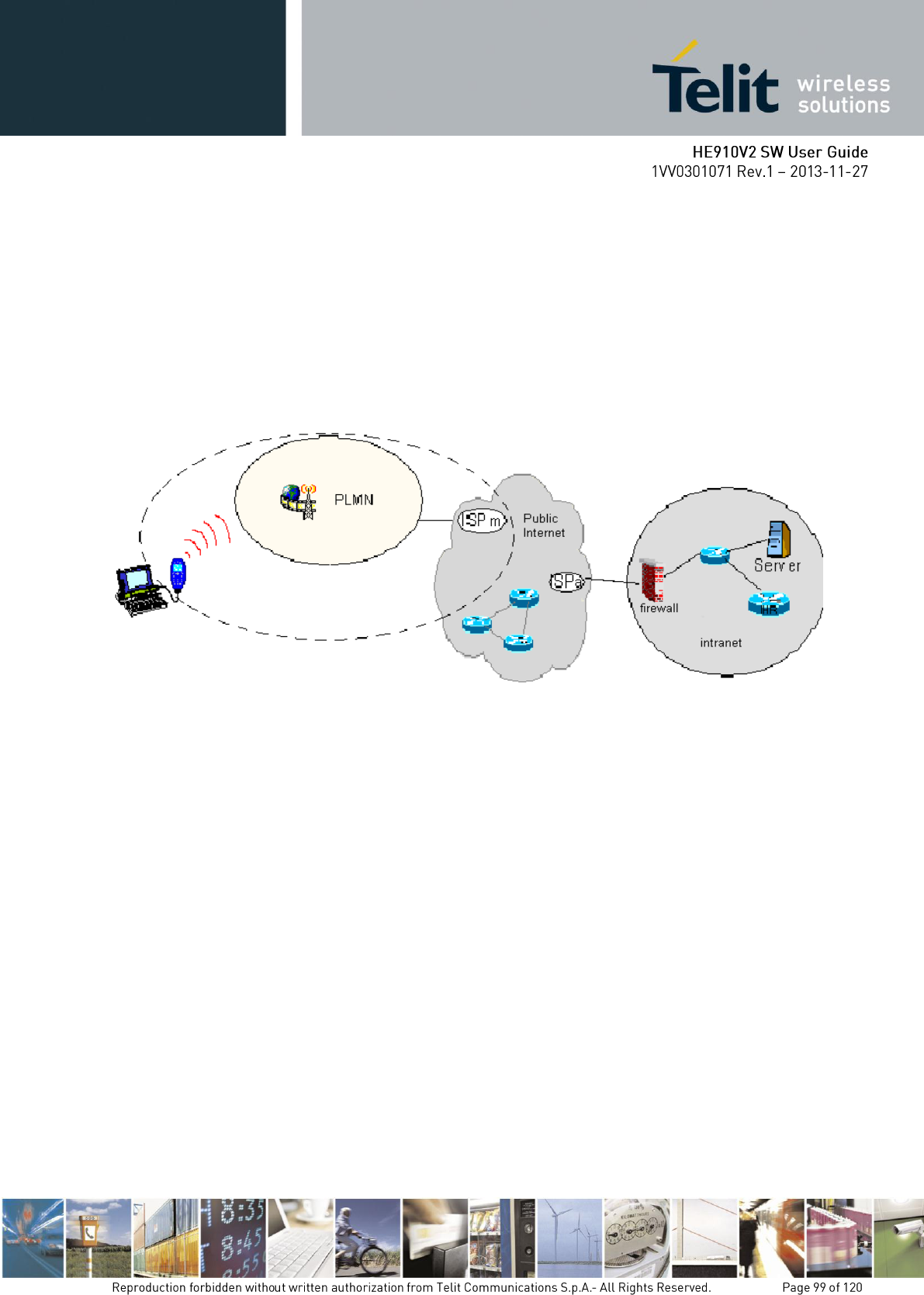
In PSD operations instead, the connection is made directly towards internet as if the PSD
modem which support GPRS/EDGE/WCDMA/HSDPA was a network IP socket interface.
There is no data path reserved for the data exchange between the two peers, instead the
resources are allocated dynamically on demand and the data exchanged is organized into
packets typically TCP/IP, furthermore the maximum transfer speed can be much faster than
GSM CSD.
An example of PSD connection is shown in the following picture, where the PSD connection
is between the PSD modem and the internet as if all the devices inside the dashed line are not
present:
Wireless Cellular PSD interconnectivity
Due to this kind of connection, when activating the PSD connection you must provide the
network parameters to enter through the internet point of the GPRS/EDGE/WCDMA/HSDPA
network ISP (Internet Service Provider) and not the phone number to be dialed. Therefore, it
is not possible to establish a direct point-to-point PSD connection between two modems as in
CSD case. Instead an internet tunneling must be done to achieve a point to point connection
between two peers.
This approach as the immediate advantage of projecting the controlling application of the
PSD modem directly on the internet, ready to be accessed virtually from anywhere in the
world at the same cost on the GPRS/EDGE/WCDMA/HSDPA network. Actually the billing
of the PSD connection is based on the amount of data exchanged (number of packets
transferred) independently from the time the connection is active or where these packets must
be delivered. Therefore, it is possible to leave the controlling application always connected
and ready to receive/send data on demand, while paying only for the data really exchanged.
The drawback of the PSD connection is that the controlling application must have its own
TCP/IP protocol stack embedded to decode the packets that arrive from
GPRS/EDGE/WCDMA/HSDPA network and encode the ones to be sent through the internet.
There are few considerations than must be done on the PSD connections:
The WCDMA connection speed is symmetrical, 384kbps in reception and
sending.

The HSDPA connection speed with a category 8 device is asymmetrical, 7.2Mbps
in reception and 384kbps in sending.
The controlling application of the module must have a TCP/IP - PPP software
stack to interface with the PSD modems.
The controlling application must relay on some ISP that may be the Network
Operator of the SIM or USIM to gain access to the internet through the PSD
connection.
Because of the point before, the receiving application must have internet access
either.
Since the communication is based upon TCP/IP packets, then it is possible to talk
contemporarily with more than one peer.
When required, the data security in internet must be guaranteed by security
protocols over the TCP/IP that must be managed by the controlling application.
The HE910V2 module is equipped with gpsOne that is controllable by the modem using a set
of AT commands or dedicated NMEA sentences.
4 serial ports are available on the module:
UART SERIAL PORT
MODEM USB SERIAL PORT
AUX USB SERIAL PORT
NMEA USB SERIAL PORT
GPS receivers perform initial position and velocity calculations using an earth-centered earth-
fixed (ECEF) coordinate system. Results may be converted to an earth model (geoid) defined
by the selected datum. For HE910V2 the default datum is WGS 84 (World Geodetic System
1984) which provides a worldwide common grid system that may be translated into local
coordinate systems or map dates. (Local map dates are a best fit to the local shape of the earth
and not valid worldwide).2
The NMEA 0183 is a specification created by the National Marine Electronics Association
(NMEA) that defines the interface between other marine electronic equipment. The standard
permits marine electronics to send information to computers and to other marine equipment.
GPS receiver communication is defined within this specification. The actually supported
version is 2.2
The provided NMEA sentences are:
GGA Time, position and fix type data.
GLL Geographic Position - Latitude/Longitude
GSA GPS receiver operating mode, satellites used in the position solution and DOP values.
GSV The number of GPS satellites in view satellite ID numbers, elevation, azimuth, and SNR
values.
RMC Time, date, position, course and speed data.
VTG Course and speed information relative to the ground
By Default the NMEA USB port provides the following sentences:
GGA, GLL, GSA, GSV, RMC, VTG.
This sentence provides time, position, and fixes related data for a GPS Receiver. Table A contains the
values for the following example:
$GPGGA,161229.487,3723.2475,N,12158.3416,W,1,07,1.0,9.0,M, , , ,0000*18
Table A
Name
Example
Units
Description
Message ID
$GPGGA
GGA protocol header
UTC Time
161229.487
hhmmss.sss
Latitude
3723.2475
ddmm.mmmm
N/S Indicator
N
N=north or S=south
Longitude
12158.3416
dddmm.mmmm
E/W Indicator
W
E=east or W=west
Position Fix
Indicator
1
See Table B
Satellites Used
07
Range 0 to 12
HDOP
1.0
Horizontal Dilution of Precision
MSL Altitude
9.0
meters
Units
M
meters
Geoid
Separation
meters
Units
M
meters
Age of Diff.
Corr.
second
Null fields when DGPS is not used
Diff. Ref.
Station ID
0000
Checksum
*18
<CR> <LF>
End of message termination
Table B
Value
Description
0
Fix not available or invalid
1
GPS SPS Mode, fix valid
2
Differential GPS, SPS Mode, fix valid
3-5
Not supported
6
Dead Reckoning Mode, fix valid
This sentence provides latitude and longitude of vessel position, time of position fix and status. Table C
contains the values for the following example:
$GPGLL,3723.2475,N,12158.3416,W,161229.487,A,A*41
Table C
Name
Example
Units
Description
Message ID
$GPGLL
GLL protocol header
Latitude
3723.2475
ddmm.mmmm
N/S Indicator
N
N=north or S=south
Longitude
12158.3416
dddmm.mmmm
E/W Indicator
W
E=east or W=west
UTC Time
161229.487
hhmmss.sss
Status
A
A=data valid or V=data not valid
Mode
A
A=Autonomous, D=DGPS, E=DR
(Only present in NMEA version 3.00)
Checksum
*41
<CR> <LF>
End of message termination
This sentence reports the GPS receiver’s operating mode, satellites used in the navigation solution
reported by the GGA sentence and DOP values. Table D contains the values for the following example:
$GPGSA,A,3,07,02,26,27,09,04,15, , , , , ,1.8,1.0,1.5*33
Table D: GSA Data Format
Name
Example
Units
Description
Message ID
$GPGSA
GSA protocol header
Mode 1
A
See Table E
Mode 2
3
See Table F
Satellite
Used1.
Satellite used
in solution.1
07
Sv on Channel 1
Satellite Used1
02
Sv on Channel 2
....
Satellite Used1
PDOP
1.8
HDOP
1.0
VDOP
1.5
Checksum
*33
<CR> <LF>
End of message termination
Table E: Mode 1
Value
Description
M
Manual—forced to operate in 2D or 3D
mode
A
2D Automatic—allowed to automatically
switch 2D/3D
Table F: Mode 2
Value
Description
1
Fix not available
2
2D (<4 SVs used)
3
3D (>3 SVs used)
This sentence reports the number of satellites (SV) in view, satellite ID numbers, elevation, azimuth
and SNR value. There could be four satellites information per transmission so; if the number of
satellites in view is bigger, separated GSV sentences will be generated. The number of sentence in
transmission and the total to be transmitted is shown in the first 2 fields of the sentence. Table G
contains the values for the following example:
$GPGSV,2,1,07,07,79,048,42,02,51,062,43,26,36,256,42,27,27,138,42*71
$GPGSV,2,2,07,09,23,313,42,04,19,159,41,15,12,041,42*41
Table G: GSV Data Format
Name
Example
Units
Description
Message ID
$GPGSV
GSV protocol header
Number of Messages
2
Range 1 to 3
Message Number1
1
Range 1 to 3
Satellites in View
07
Satellite ID
07
Channel 1 (Range 1 to 32)
Elevation
79
degrees
Azimuth
048
degrees
SNR (C/No)
42
dBHz
....
....
....
Satellite ID
27
Channel 4 (Range 1 to 32)
Elevation
27
degrees
Channel 4 (Maximum 90)
Azimuth
138
degrees
Channel 4 (True, Range 0 to 359)
SNR (C/No)
42
dBHz
Range 0 to 99, null when not tracking
Checksum
*71
<CR> <LF>
End of message termination
This sentence reports Time, date, position, and course and speed data. Table H contains the values for
the following example:
$GPRMC,161229.487,A,3723.2475,N,12158.3416,W,0.13,309.62,120598, ,*10
Table H: RMC Data Format
Name
Example
Units
Description
Message ID
$GPRMC
RMC protocol header
UTC Time
161229.487
hhmmss.sss
Status
A
A=data valid or V=data not valid
Latitude
3723.2475
ddmm.mmmm
N/S Indicator
N
N=north or S=south
Longitude
12158.3416
dddmm.mmmm
E/W Indicator
W
E=east or W=west
Speed Over
Ground
0.13
knots
Course Over
Ground
309.62
degrees
True
Date
120598
ddmmyy
Magnetic
Variation
degrees
E=east or W=west
Mode
A
A=Autonomous, D=DGPS, E=DR
Checksum
*10
<CR> <LF>
End of message termination
This sentence reports the actual course and speed relative to the ground.
Table I contains the values for the following example:
$GPVTG,309.62,T, ,M,0.13,N,0.2,K,A*23
Table I: VTG Data Format
Name
Example
Units
Description
Message ID
$GPVTG
VTG protocol header
Course
309.62
Measured heading
Reference
T
True
Course
degrees
Measured heading
Reference
M
Magnetic
Speed
0.13
knots
Measured horizontal speed
Units
N
Knots
Speed
0.2
km/hr
Measured horizontal speed
Units
K
Kilometers per hour
Mode
A
A=Autonomous, D=DGPS, E=DR
Checksum
*23
<CR> <LF>
End of message termination
After a proper power on, the device is ready to receive AT commands on the MODEM serial
port.
The GPS receiver also will be automatically powered on and it will start the scan of the
available GPS signals.
On the NMEA USB port (default 115200 bps, 8, n, 1) there must be presence of the NMEA
sentences.
The HE910V2 module is provided by a set of AT commands that permits to configure and
use it through the MODEM serial port.
The GPS receiver is by default switched off at the first power on. If is necessary to switch it
on or off is possible to use the AT$GPSP command. The GPS receiver is usable if the GSM
module is switched on (or at least in power saving). This command also switches off the GPS
antenna supply.
Syntax of the command AT$GPSP=<status>
Where:
<status> - 0 GPS controller is powered down(default), 1 GPS controller is powered up, ?
Returns the range of values accepted
AT$GPSP? will return the current status.
Example 1: (to switch on the GPS)
AT$GPSP=1<CR>
OK
Example 2 : (to know the status)
AT$GPSP?<CR>
The answer will be:
$GPSP: 0
OK
With the command AT$GPSR=<reset type> is possible to reset the GPS module.
Parameter:
<reset type>
0 - Factory reset: This option clears all GPS memory including clock drift. It is available in
controlled mode only.
1 - Coldstart (No Almanac, No Ephemeris): this option clears all data that is currently stored in the
internal memory of the GPS receiver including position, almanac, ephemeris, and time. The stored
clock drift however, is retained. It is available in controlled mode only.
2 - Warmstart (No ephemeris): this option clears all initialization data in the GPS receiver and
subsequently reloads the data that is currently displayed in the Receiver Initialization Setup screen. The
almanac is retained but the ephemeris is cleared. It is available in controlled mode only.
3 - Hotstart (with stored Almanac and Ephemeris): the GPS receiver restarts by using the values
stored in the internal memory of the GPS receiver; validated ephemeris and almanac. It is available in
controlled mode only.
Example:
Let’s suppose to perform a cold start of the GPS receiver.
AT$GPSR=1<cr>
OK
The Receiver will clear all the parameters in its memory and it will start a new scanning of the
available satellites.
This command allows saving the set parameters in the module’s memory
Syntax of the command
AT$GPSSAV
After this command restart the module to update the modifications.
This command allows restoring the factory default parameters for the GPS module
Syntax of the command:
AT$GPSRST
After this command restart the module to update the modifications.
This command allows reading the acquired position of the GPS receiver
Syntax of the command
AT$GPSACP
The response syntax is:
$GPSACP:<UTC>,<latitude>,<longitude>,<hdop>,<altitude>,<fix>,<cog>,
<spkm>,<spkn>,<date>,<nsat>
The fields contain the following information:
<UTC>: (referred to GGA sentence)
hhmmss UTC of Position
Values:
hh (hour) 00 to 23
mm (minutes) 00 to 59
ss (seconds) 00 to 59
<latitude>: (referred to GGA sentence)

ddmm.mmmm N/S
Values:
dd (degrees) 00 to 90
mm.mmmm (minutes) 00,0000 to 59.9999
N/S: North / South
<longitude>: (referred to GGA sentence)
dddmm.mmmm E/W
Values:
ddd (degrees) 00 to 180
mm.mmmm (minutes) 00,0000 to 59.9999
E/W: East / West
<hdop>: (referred to GGA sentence)
x.x Horizontal Diluition of Precision
<altitude>: (referred to GGA sentence)
xxxx.x Altitude - mean-sea-level (geoid) (meters)
<fix>:
0 - Invalid Fix
2 - 2D fix
3 - 3D fix
<cog>: (referred to VTG sentence)
ddd.mm Course over Ground (degrees, True)
Values:
ddd: 000 to 360 degrees
mm 00 to 59 minutes
<spkm>: (referred to VTG sentence)
xxxx.x Speed over ground (Km/hr)
<spkn>: (referred to VTG sentence)
xxxx.x Speed over ground (knots)
<date>: (referred to RMC sentence)
ddmmyy Date of Fix
Values:
dd (day) 01 to 31
mm (month) 01 to 12
yy (year) 00 to 99 (2000 to 2099)
<nsat>: (referred to GSV sentence)
nn Total number of satellites in use
Example:
$GPSACP:080220,4542.82691N,01344.26820E,259.07,3,2.1,0.1,0.0,0.0,270705,09
OK
The GLONASS is enabled / disabled at boot time. The GLONASS is by default enabled. The
information of GLONASS satellites can show the NMEA string format with
AT$GPSNMUNEX command. If the GLONASS is enabled/disabled with AT$GPSGLO
command, it is necessary that the module should be powered off and on.
Syntax of the command AT$GPSGLO=<type>
Where:
<type>
0 – Disable GNSS(or GLONASS)
1 – Enable GNSS(or GLONASS) (Factory default)
Example 1: (to enable the GLONASS)
AT$GPSGLO=1<CR>
OK
The module needs to power off and on (Reboot).
AT$GPSP=1<CR> ( to switch on the GPS)
OK
AT$GPSNMUNEX=1,1,1<CR>
OK
The module will display the information of GLONASS.
Example 2 : (to disable the GLONASS)
AT$ GPSGLO=0<CR>
OK
The module needs to power off and on (Reboot).
AT$GPSP=1<CR> ( to switch on the GPS)
OK
AT$GPSNMUNEX=0,0,0<CR>
OK

The module won’t display the information of GLONASS.
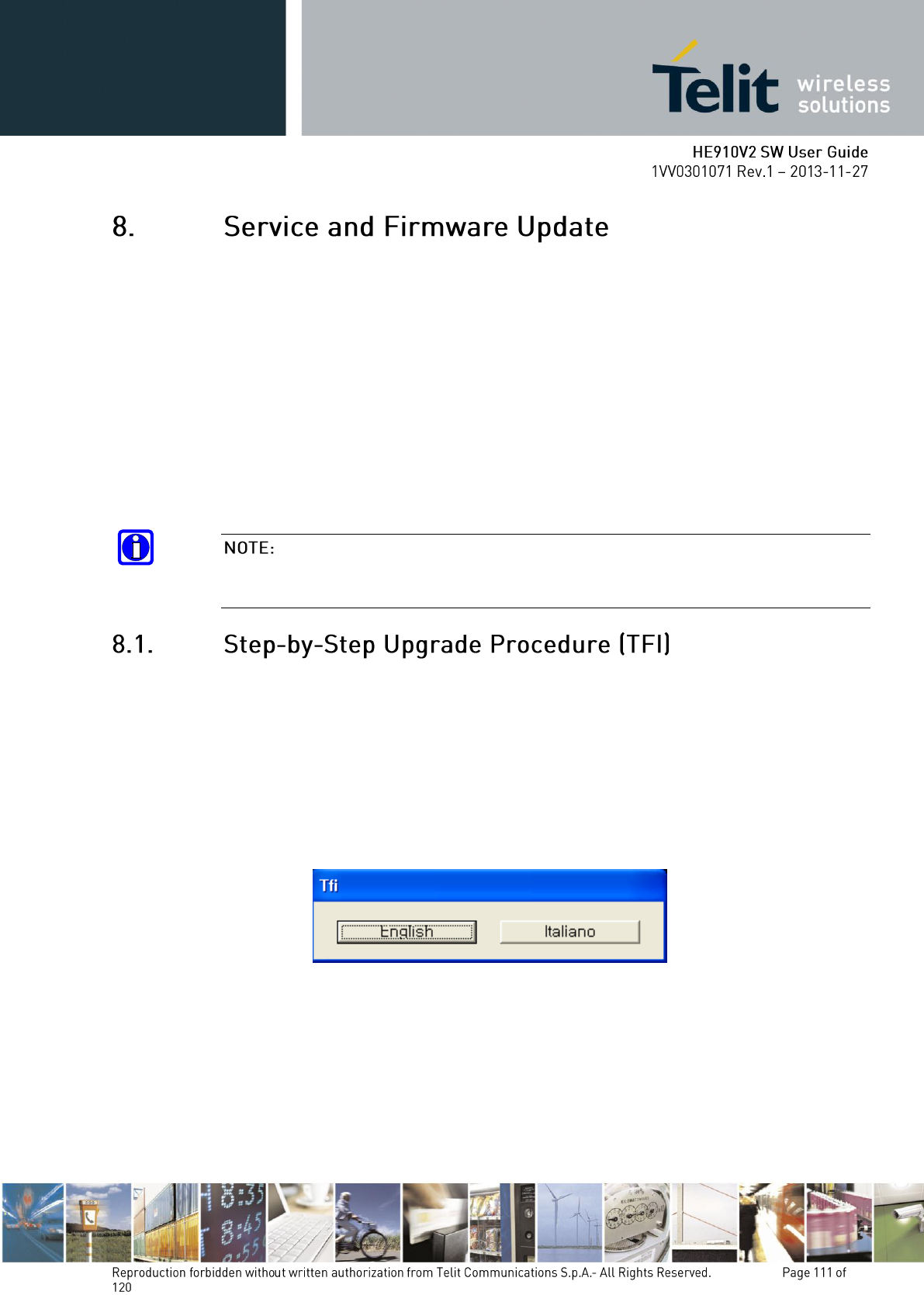
The Telit Modules firmware is updated through the Serial Interface normally used for the AT
Commands.
It is suggested to provide an RS232 interface on the User Printed Circuit Board (where the
Telit Module is soldered) to perform the physical connection between the Telit module and a
Windows-based PC. That simple circuitry makes the firmware updating easy when a new
firmware version is released.
During the User Application development or evaluation phase of the Telit module, the
RS232 interface or the USB port implemented on the Telit Evaluation Kit (EVK2) [6] can
be used to connect the Telit module to a Windows-based PC on which a dedicated tool for
firmware updating is running.
Telit provides the User with two tools to update the firmware of the module. The following
paragraphs describe them.
GT terminals are complete encased modems. They do not need the Telit Evaluation Kit
(EVK2) to perform testing, evaluation and Firmware Update.
The firmware update can be done with a specific software tool provided by Telit that runs on
Windows based PCs.
First the program will erase the content of flash memory, and then the program will write on
the flash memory. To update the firmware of the module, we suggest the following procedure:
Run the file TFI_xxxx.exe. The following window must be displayed, select the
language preferred by pressing the correspondent button.
The End User License Agreement will appear. Please, read it and accept the terms
if you are going to proceed.
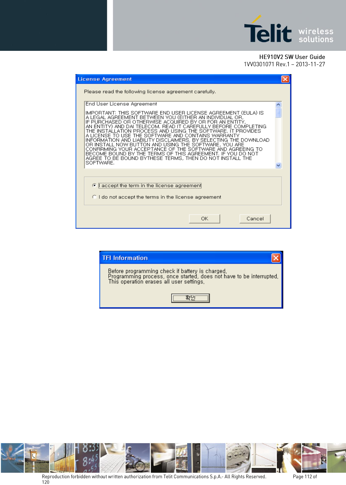
Press OK to the initial message.
Note: In connection with the HE910V2 modules, charged battery has to be understood that
the power supply must not be disconnected during the firmware update.
Download ready screen – If “Diagnostic” COM Port is automatically detected
then the baudrate is fixed to 230400. But automatically port detection is
depending on Window OS and it is targeting on Window XP. If COM Port is not
detecting then must recheck that connecting status of modem USB cable and
USB driver installation. Firmware Version displayed on Title bar is new firmware
version and this version will be updated to the module.
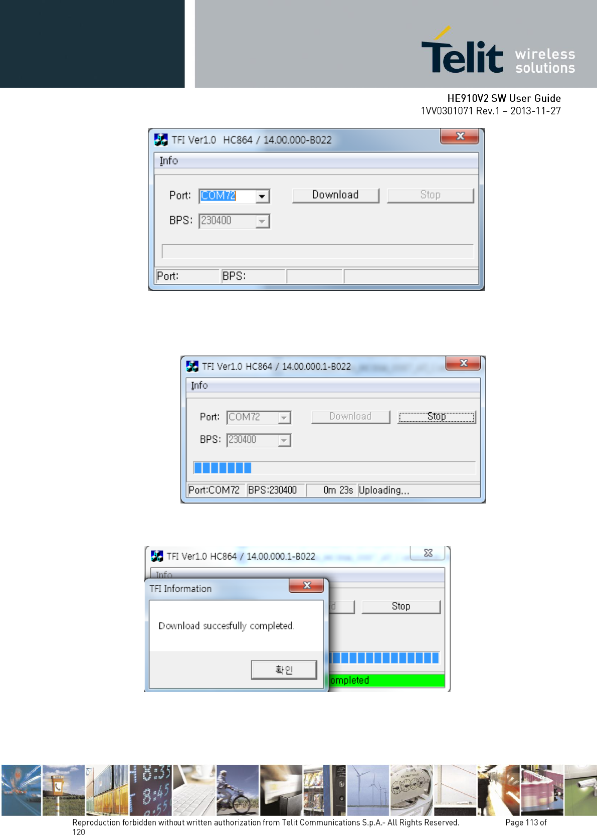
Select the right COM port and speed. Note that to go faster than 115200 you need
a special hardware on the PC. Then Press the Download button and within 5
seconds power-on the HE910V2.
Firmware Version displayed on Title bar is current firmware version.
Wait for the end of programming green message OK.
The Telit HE910V2 module is now programmed with the new firmware.
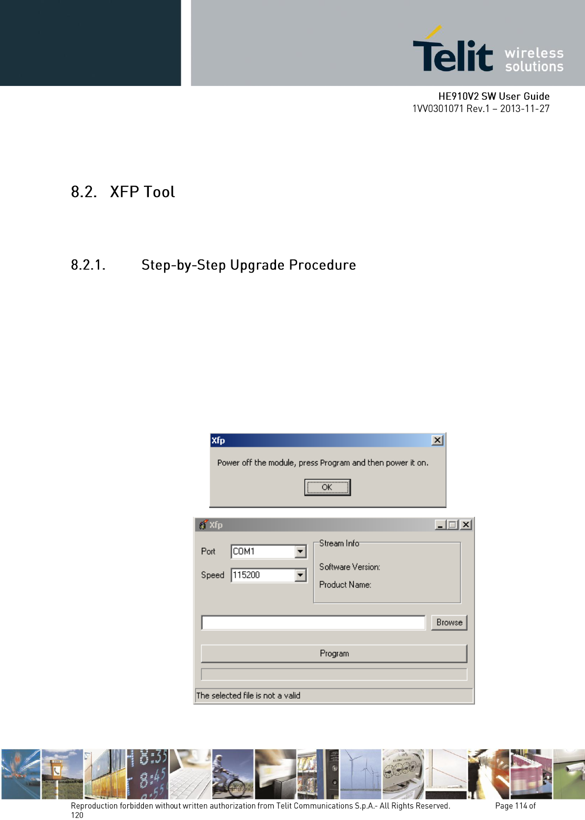
The firmware update of the module can be performed with the Xfp Tool provided by Telit. It
runs on Windows based PCs. It erases the flash memory content, and then it downloads the
new firmware on the flash memory.
To update the Telit Module firmware, follow the procedure:
1. collect information about the Telit Module and Software version using the following AT
commands:
AT+CGMR<cr>, returns the Software version information;
AT+CGMM<cr>, returns the Telit Module identification.
2. Switch OFF the Telit Module.
3. Run the Xfp.exe tool, the following windows are displayed. Power OFF the module if needed
then press OK button.
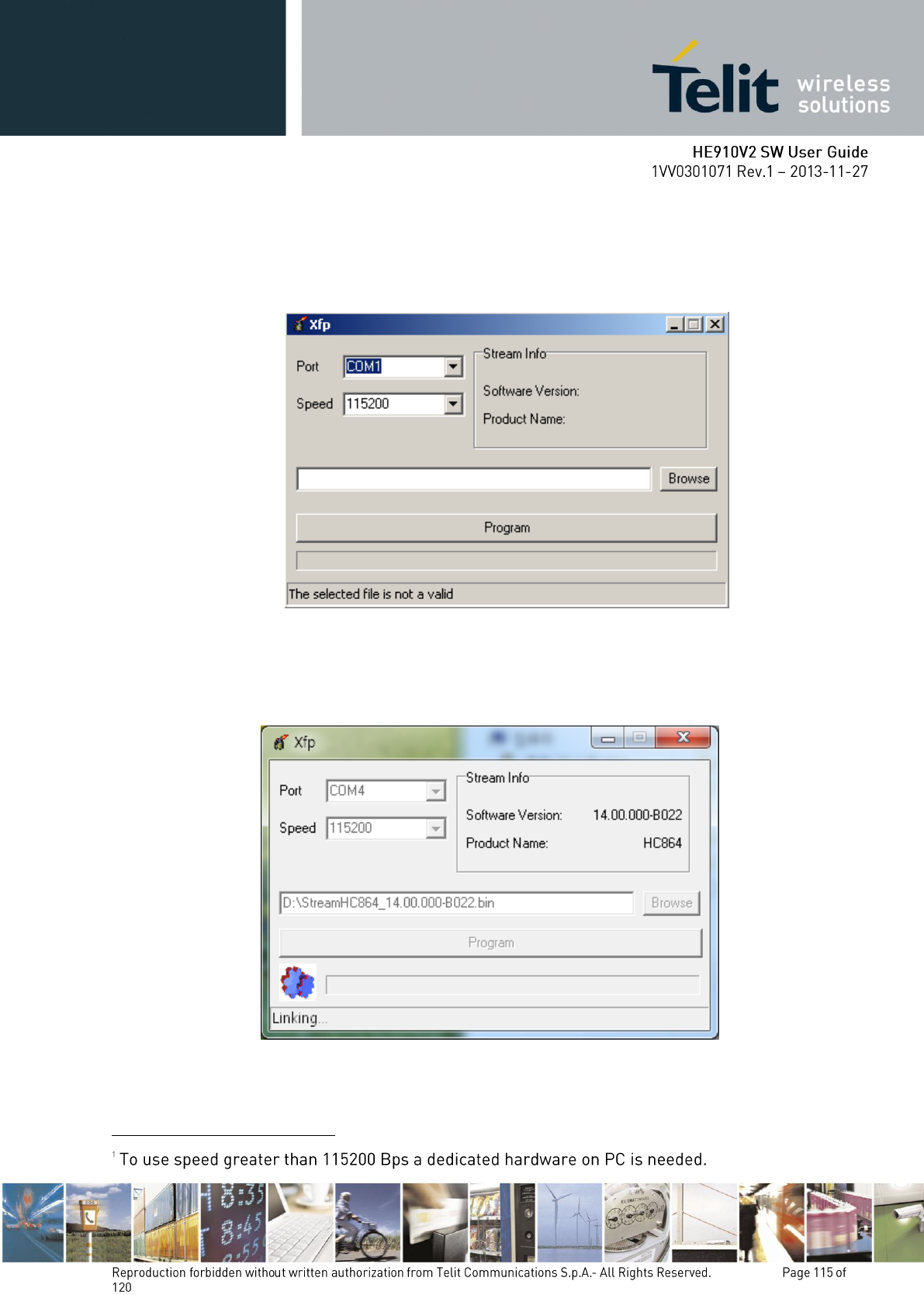
4. After pressing OK button on the screen is displayed only the following windows.
5. After selecting COM port, speed
1
and stream file (stream files holds new firmware) press
Program button, a flashing blue bar appears on the displayed window. The following window
is displayed on the screen.
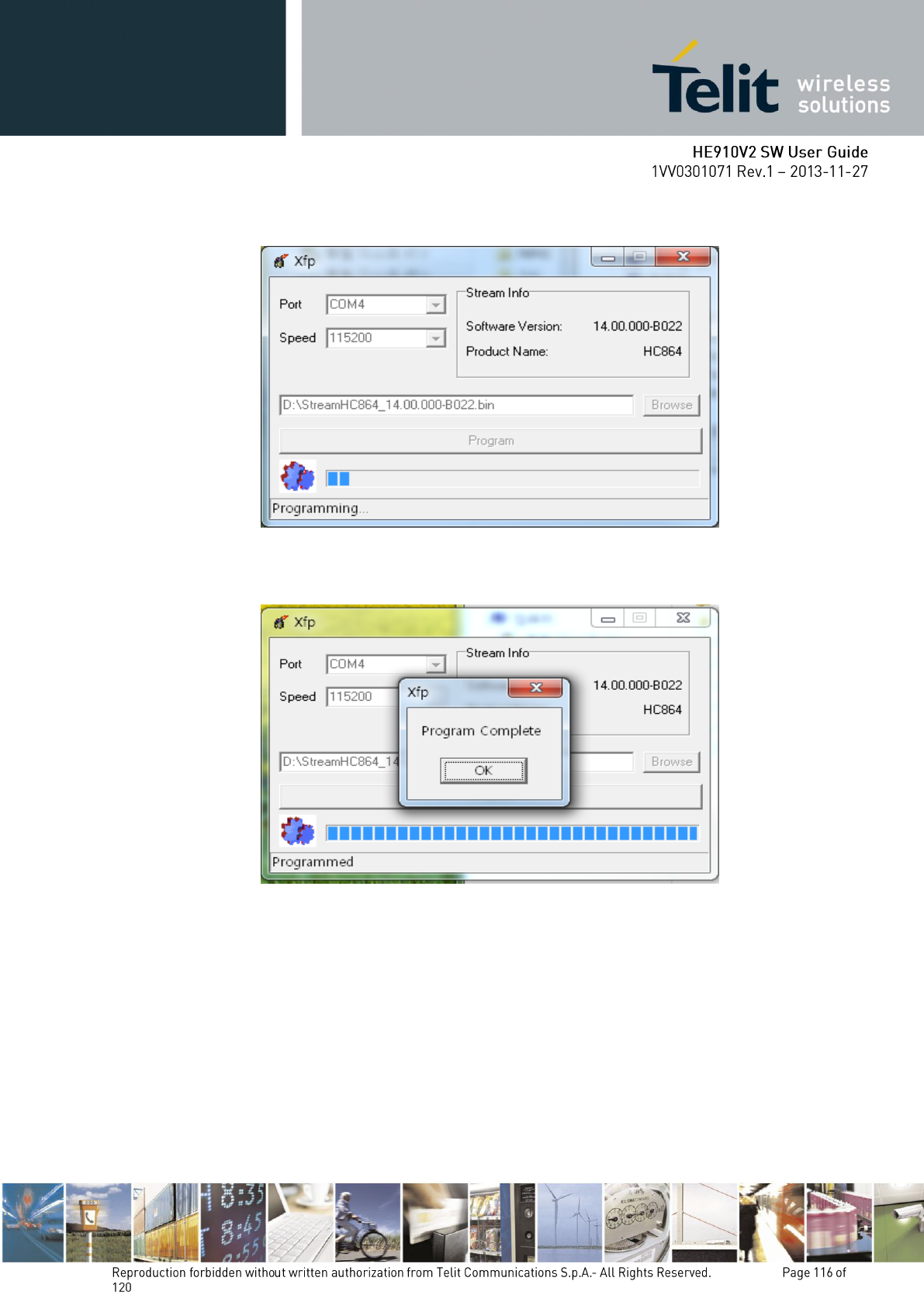
6. After powering ON the module the following window is displayed on the screen. The
programming is in progress
7. The following window is displayed on the screen when the module is successfully
programmed.
8. Now the Telit module is programmed with the new firmware. Press OK button and exit the
tool.
Modification statement
Telit has not approved any changes or modifications to this device by the user. Any changes or modifications
could void the user’s authority to operate the equipment.
Telit n’approuve aucune modification apportée à l’appareil par l’utilisateur, quelle qu’en soit la nature. Tout
changement ou modification peuvent annuler le droit d’utilisation de l’appareil par l’utilisateur.
Interference statement
This device complies with Part 15 of the FCC Rules and Industry Canada licence-exempt RSS standard(s).
Operation is subject to the following two conditions: (1) this device may not cause interference, and (2) this
device must accept any interference, including interference that may cause undesired operation of the device.
This Class B digital apparatus complies with Canadian ICES-0003.
Le présent appareil est conforme aux CNR d'Industrie Canada applicables aux appareils radio exempts de
licence. L'exploitation est autorisée aux deux conditions suivantes : (1) l'appareil ne doit pas produire de
brouillage, et (2) l'utilisateur de l'appareil doit accepter tout brouillage radioélectrique subi, même si le
brouillage est susceptible d'en compromettre le fonctionnement.
Wireless notice
This equipment complies with FCC and IC radiation exposure limits set forth for an uncontrolled environment.
The antenna should be installed and operated with minimum distance of 20 cm between the radiator and your
body. Antenna gain must be below:
Frequency band
HE910-NA V2
HE910-NAG V2
GSM/GPRS850
7.43 dBi
7.43 dBi
FDD V
8.45 dBi
8.45 dBi
GSM/GPRS1900 / FDD II
3.0 dBi
3.0 dBi
This transmitter must not be co-located or operating in conjunction with any other antenna or transmitter.
Cet appareil est conforme aux limites d'exposition aux rayonnements de la IC pour un environnement non
contrôlé. L'antenne doit être installé de façon à garder une distance minimale de 20 centimètres entre la
source de rayonnements et votre corps. Gain de l'antenne doit être ci-dessous:
Bande de fréquence
HE910-NA V2
HE910-NAG V2
GSM/GPRS850
7.43 dBi
7.43 dBi
FDD V
8.45 dBi
8.45 dBi
GSM/GPRS1900 / FDD II
3.0 dBi
3.0 dBi
L'émetteur ne doit pas être colocalisé ni fonctionner conjointement avec à autre antenne ou autre émetteur.
FCC Class B digital device notice
This equipment has been tested and found to comply with the limits for a Class B digital device, pursuant to
part 15 of the FCC Rules. These limits are designed to provide reasonable protection against harmful
interference in a residential installation. This equipment generates, uses and can radiate radio frequency
energy and, if not installed and used in accordance with the instructions, may cause harmful interference to
radio communications. However, there is no guarantee that interference will not occur in a particular
installation. If this equipment does cause harmful interference to radio or television reception, which can be
determined by turning the equipment off and on, the user is encouraged to try to correct the interference by
one or more of the following measures:
- Reorient or relocate the receiving antenna.
- Increase the separation between the equipment and receiver.
- Connect the equipment into an outlet on a circuit different from that to which the receiver is connected.
- Consult the dealer or an experienced radio/TV technician for help.
Information To Be Supplied to the End User by the OEM or Integrator notice
Modular information form OEM Information to Be Supplied to the End User by the OEM or Integrator
The following regulatory and safety notices must be published in documentation supplied to the end user of
the product or system incorporating an adapter in compliance with local regulations. Host system must be
labeled with "Contains IC: 5131A-HE910NAV2 " or "Contains FCCID:RI7HE910NAV2 ", FCC ID/IC

displayed on label.
