Telit Communications S p A UC864AWA GSM 850, E-GSM 900, DCS 1800, PCS 1900, FDD IV, 2G/3.5G module User Manual Users guide
Telit Communications S.p.A. GSM 850, E-GSM 900, DCS 1800, PCS 1900, FDD IV, 2G/3.5G module Users guide
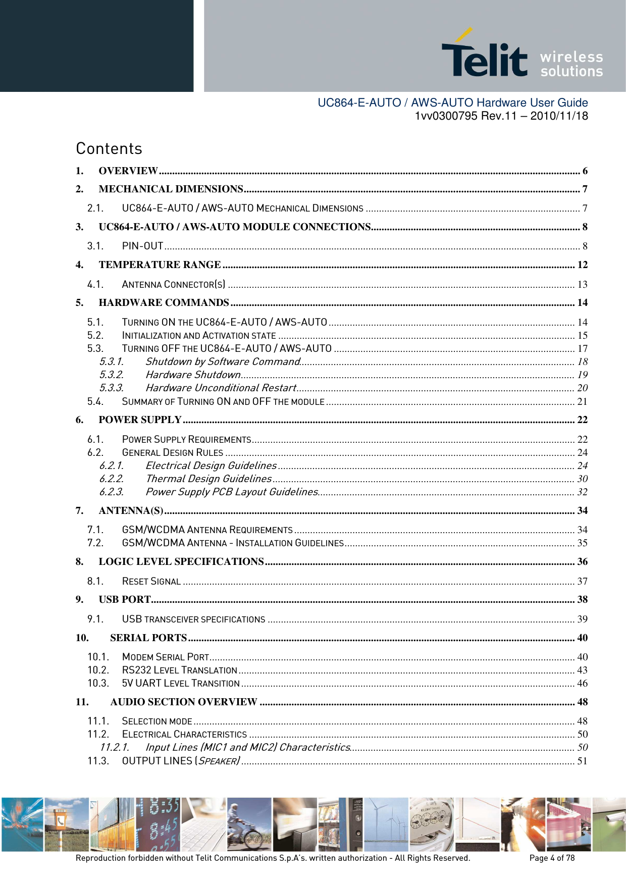
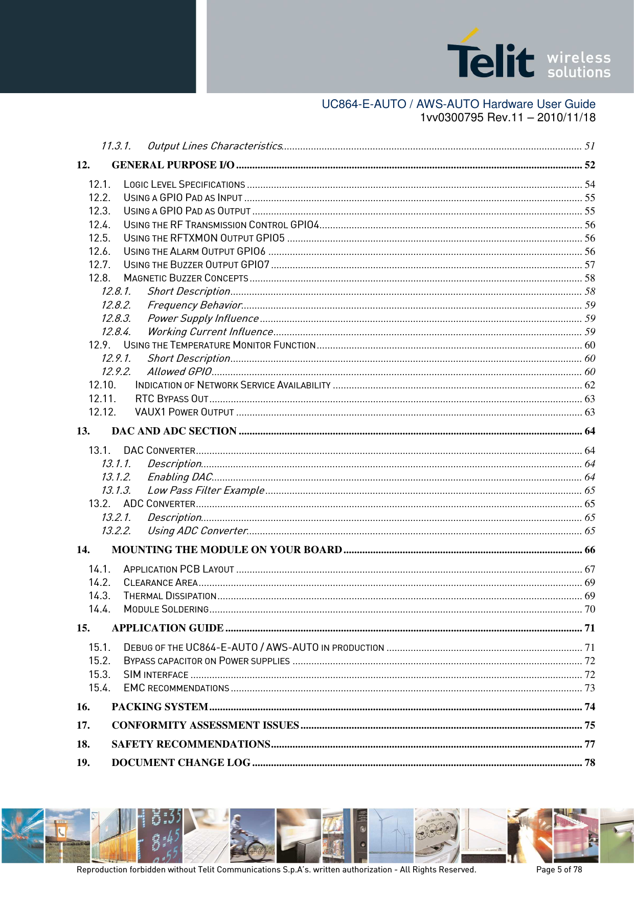
Contents
- 1. User guide
- 2. Users guide
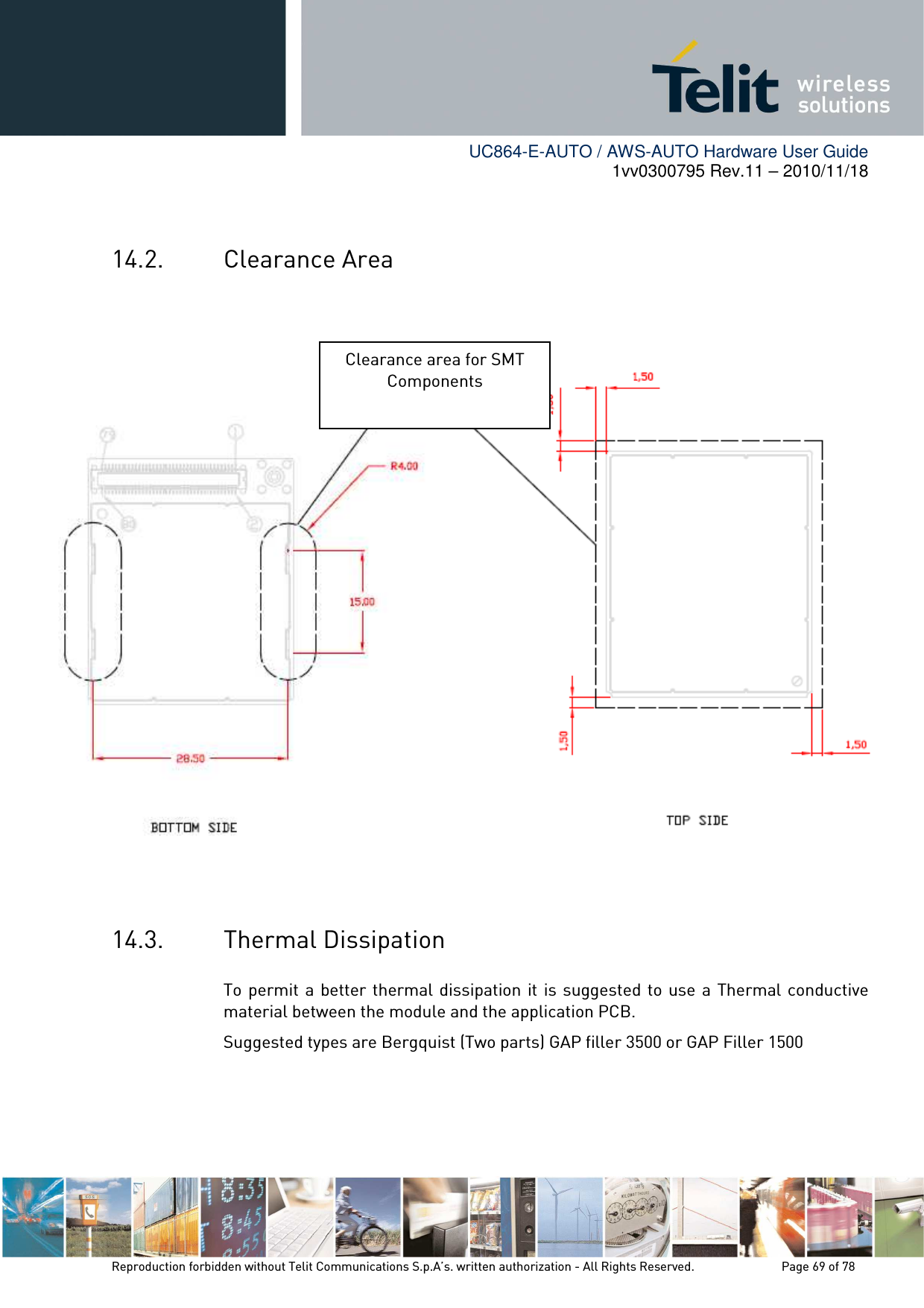
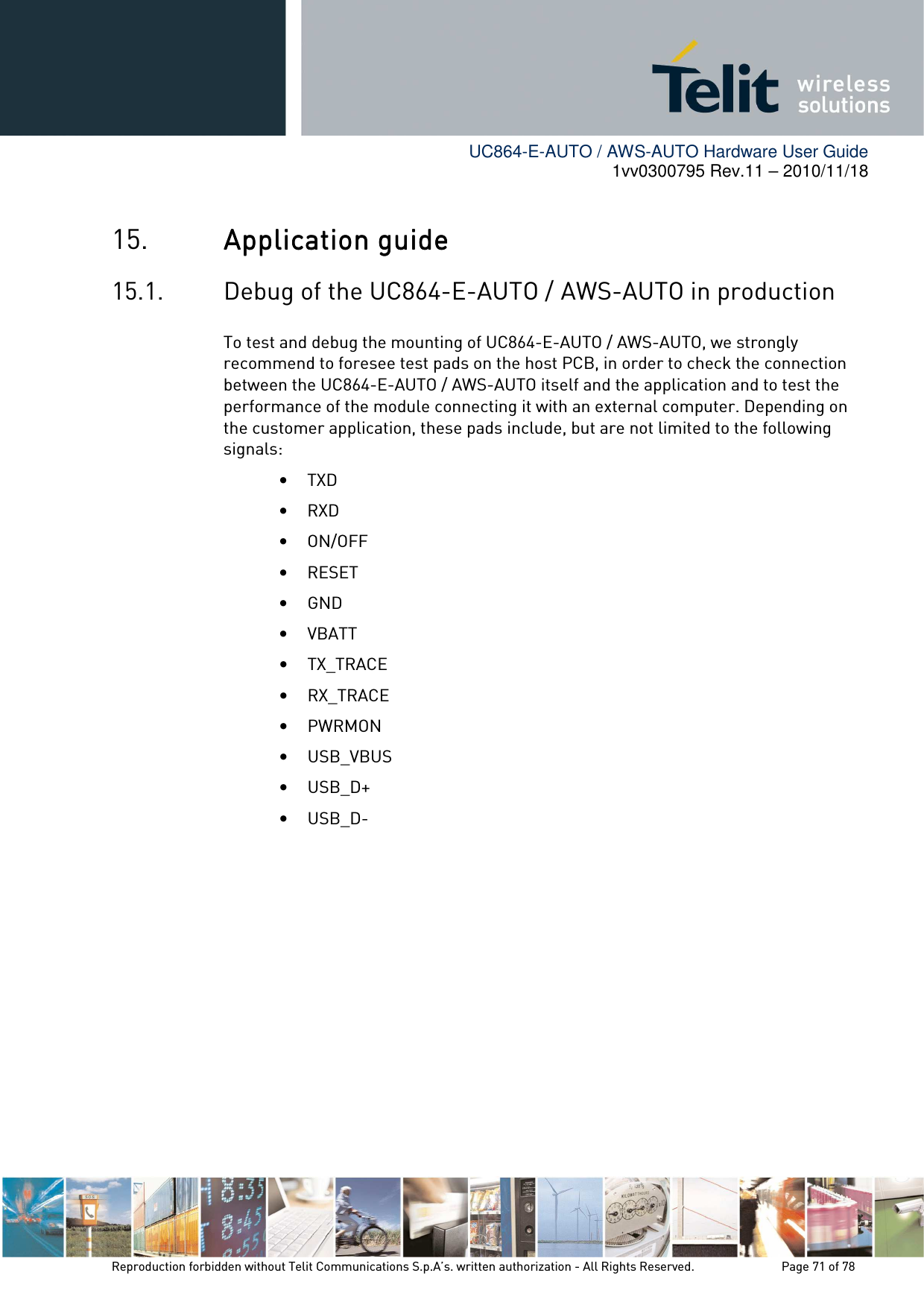
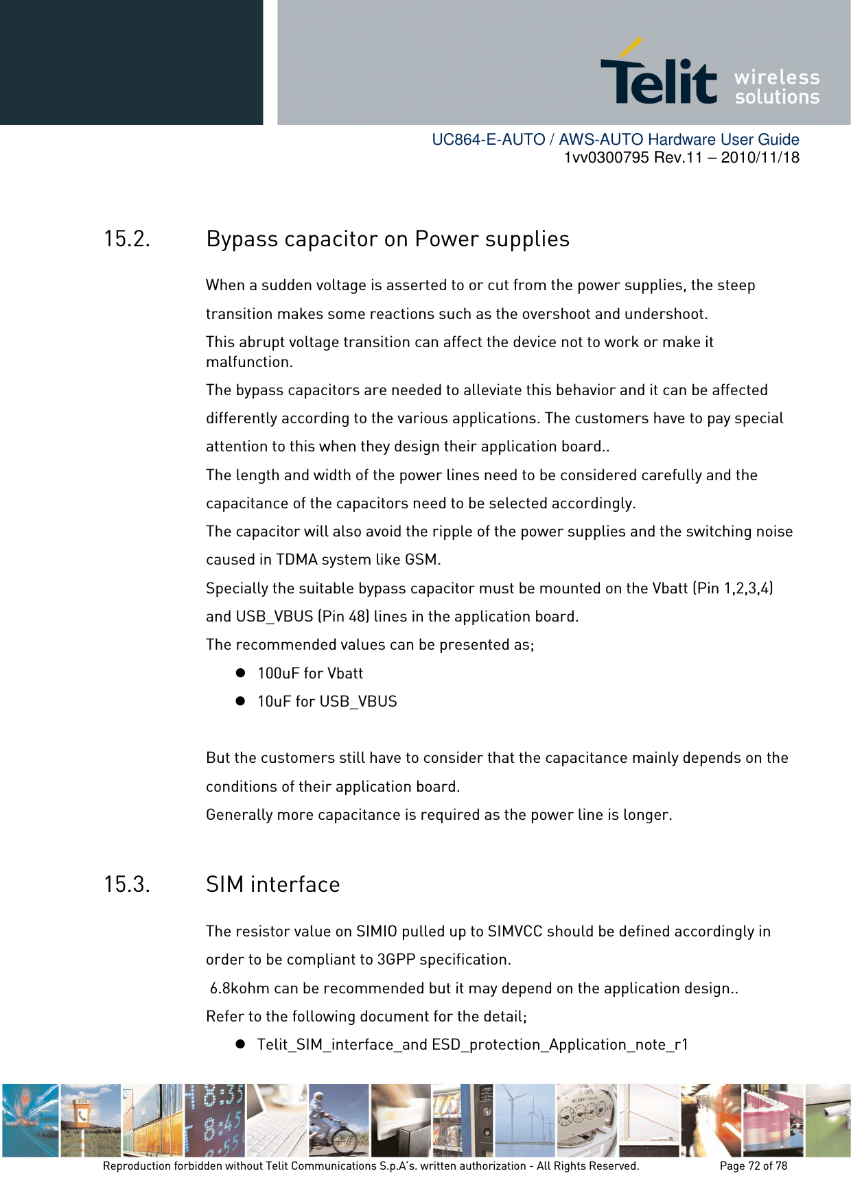
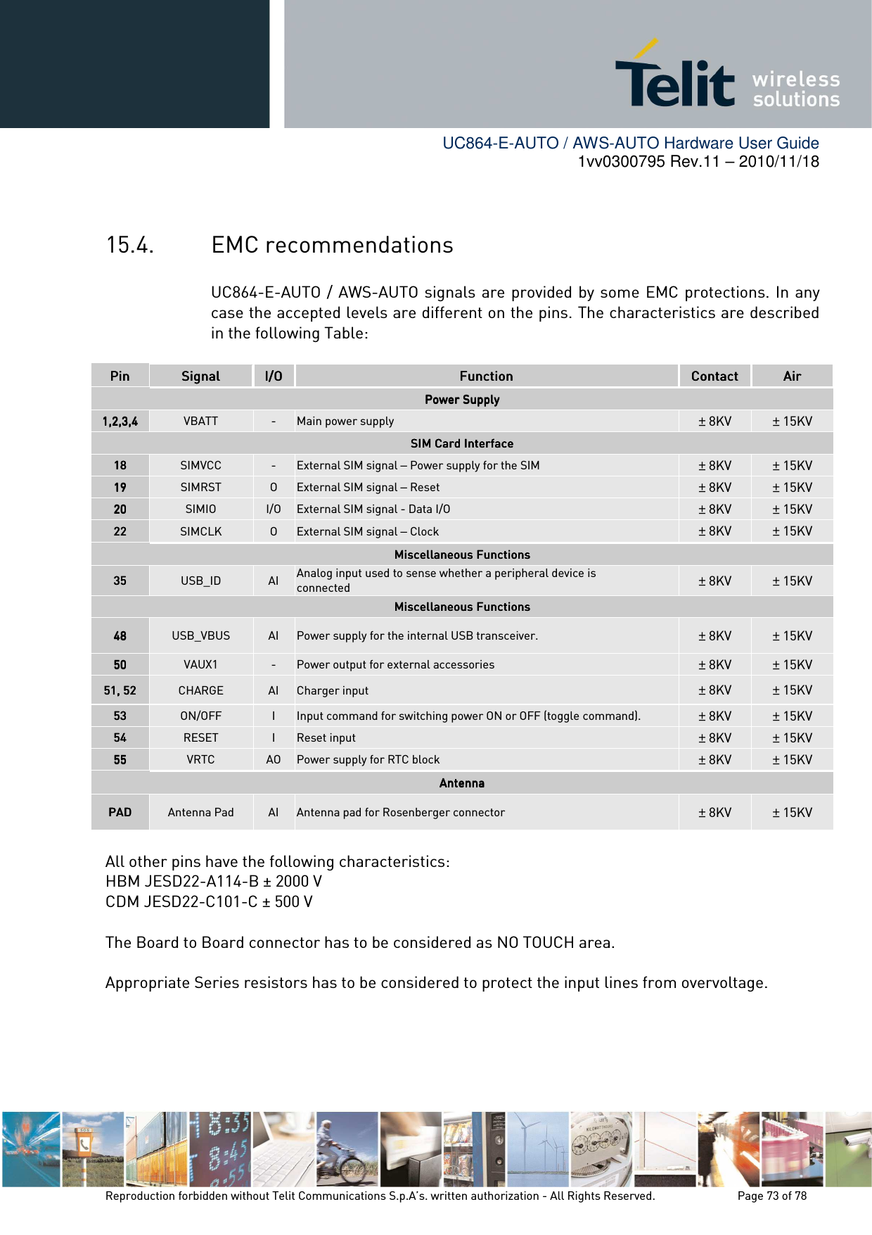
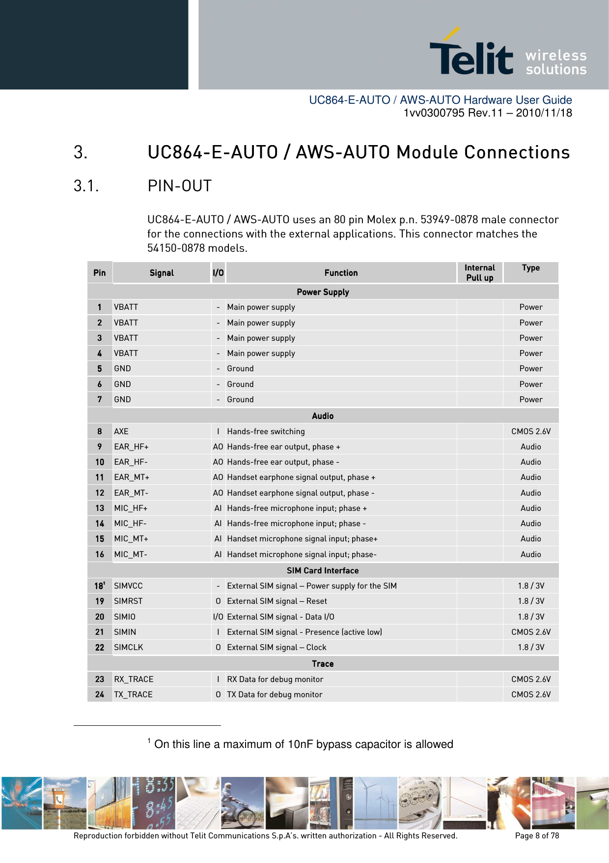
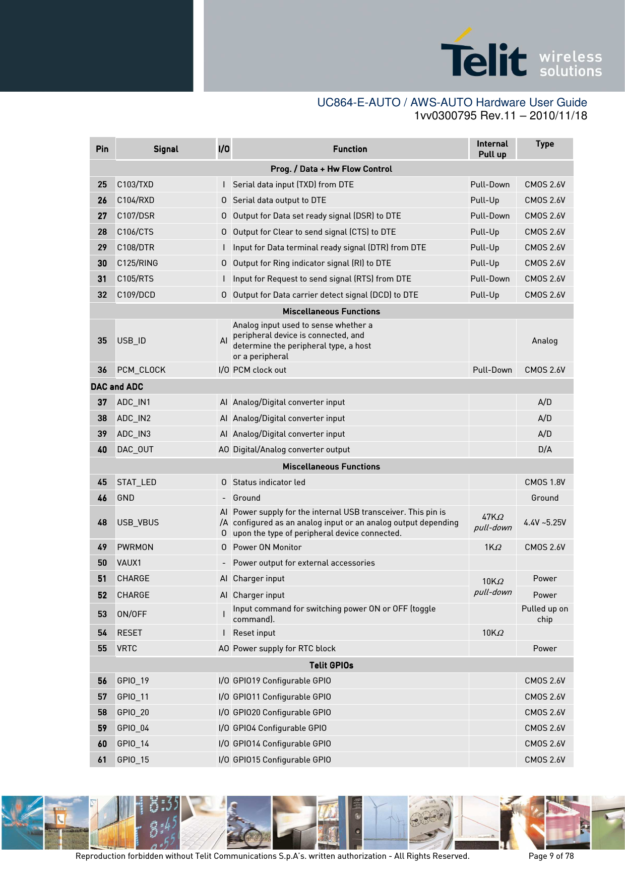
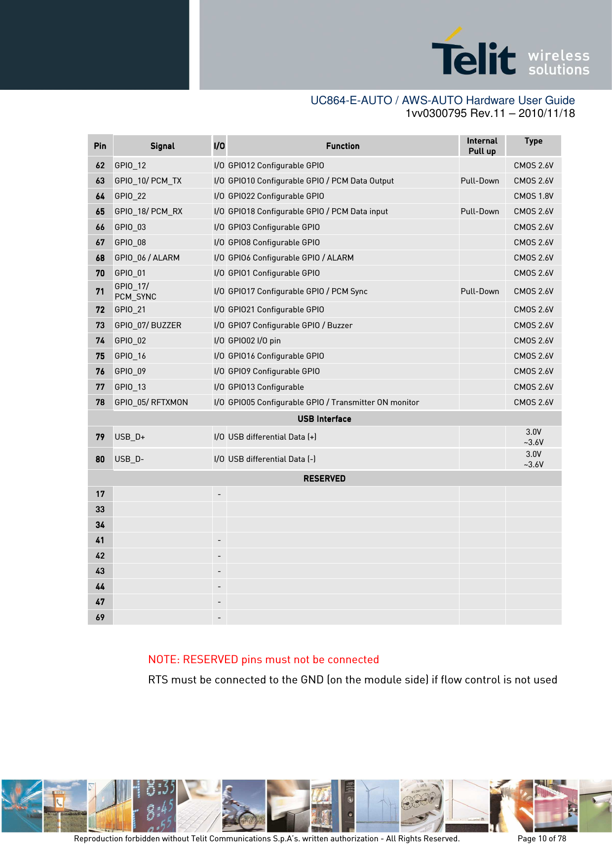
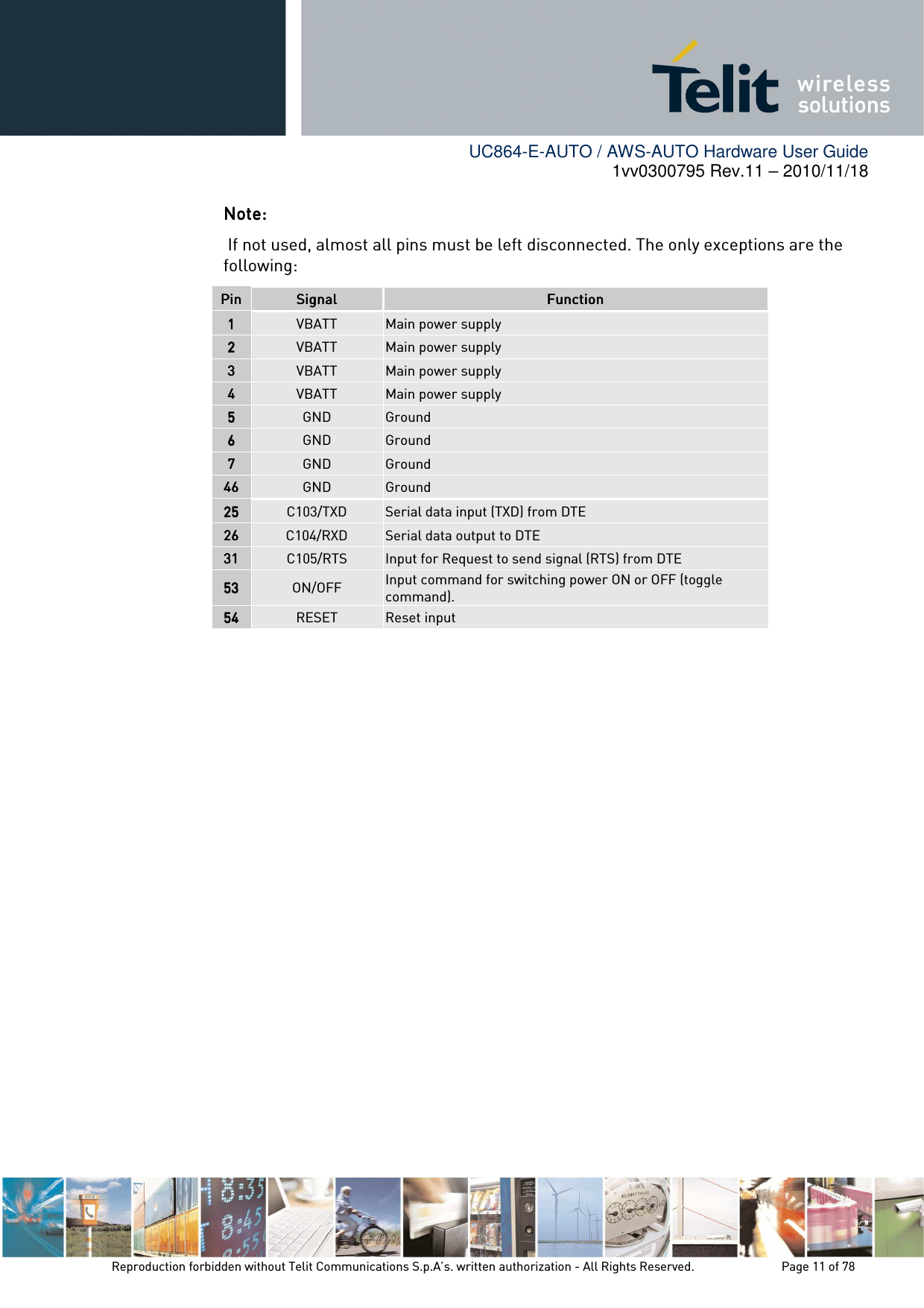
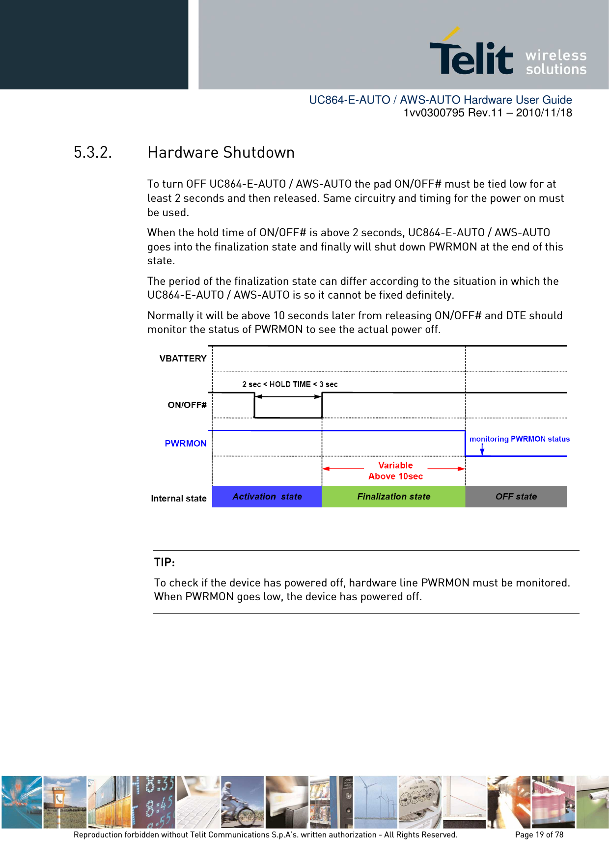
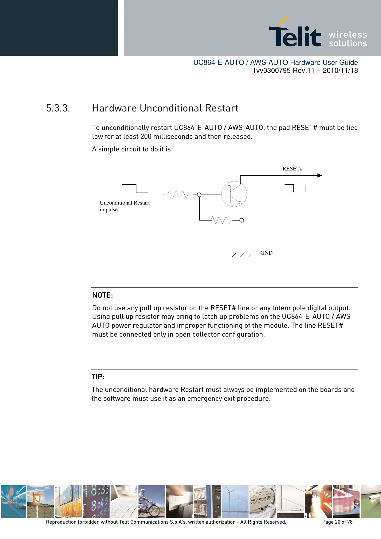
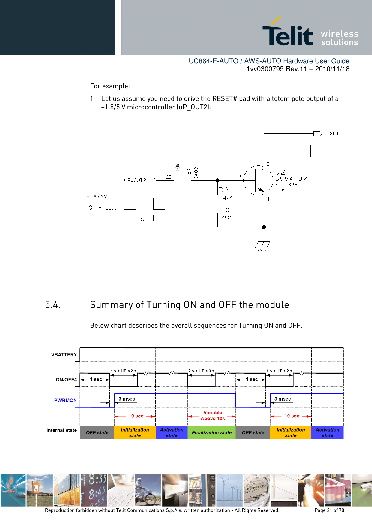
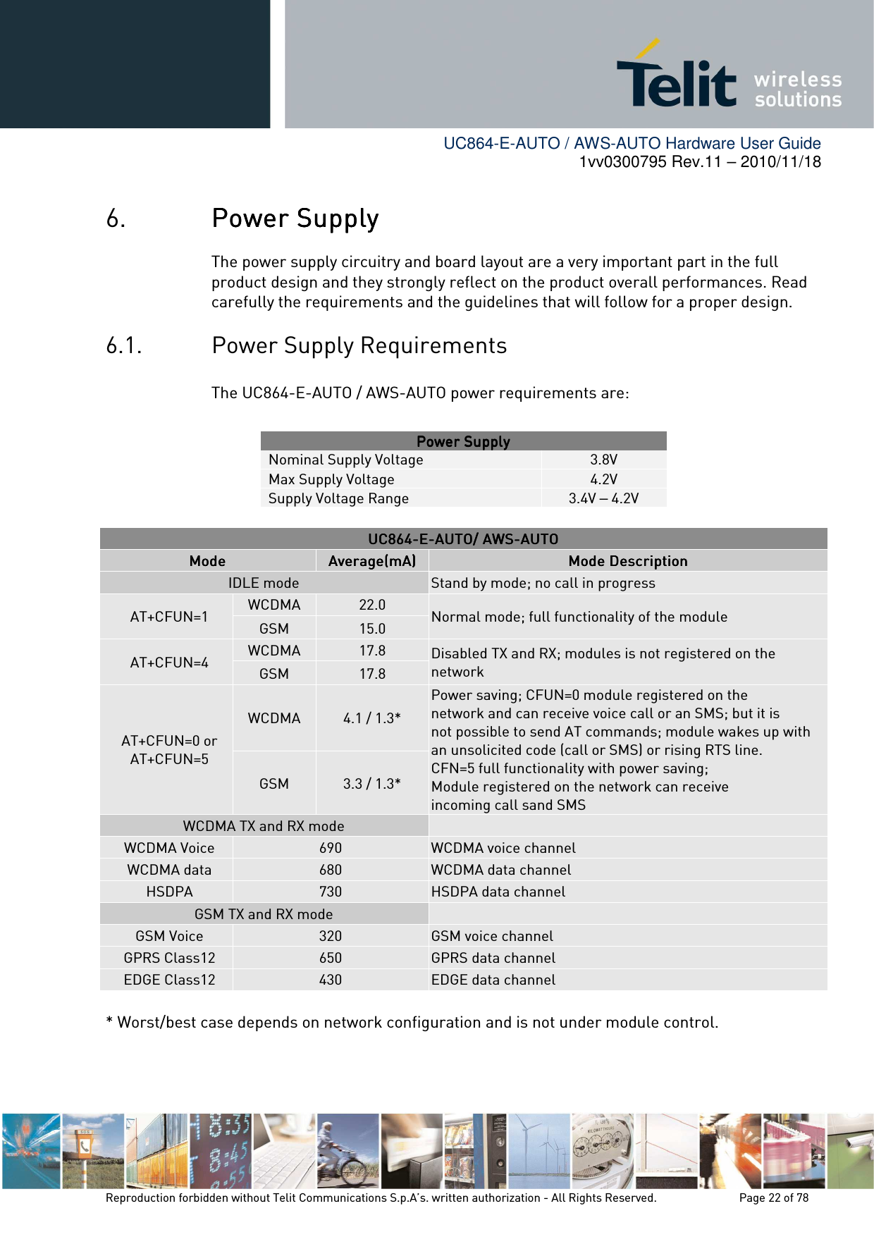
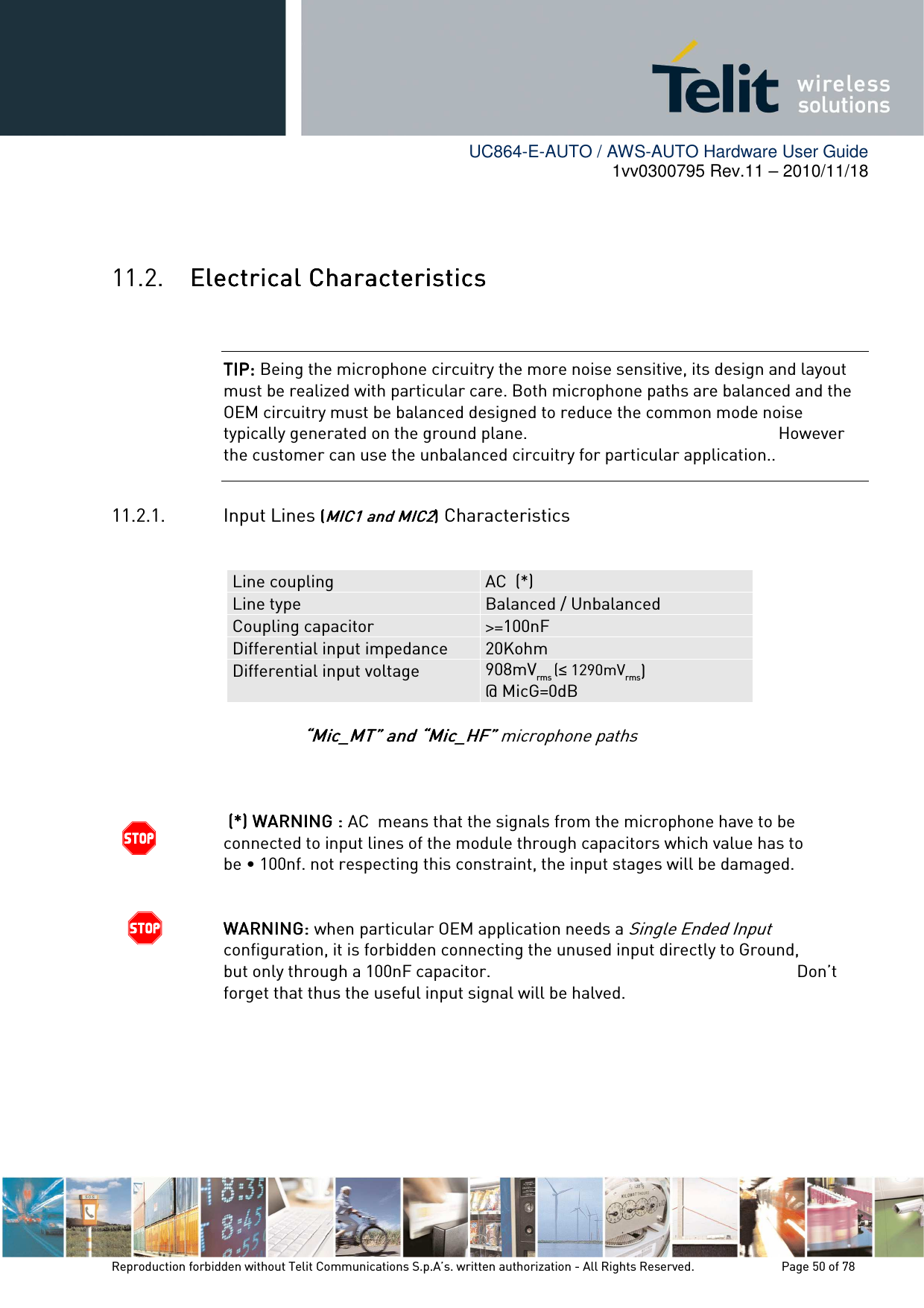
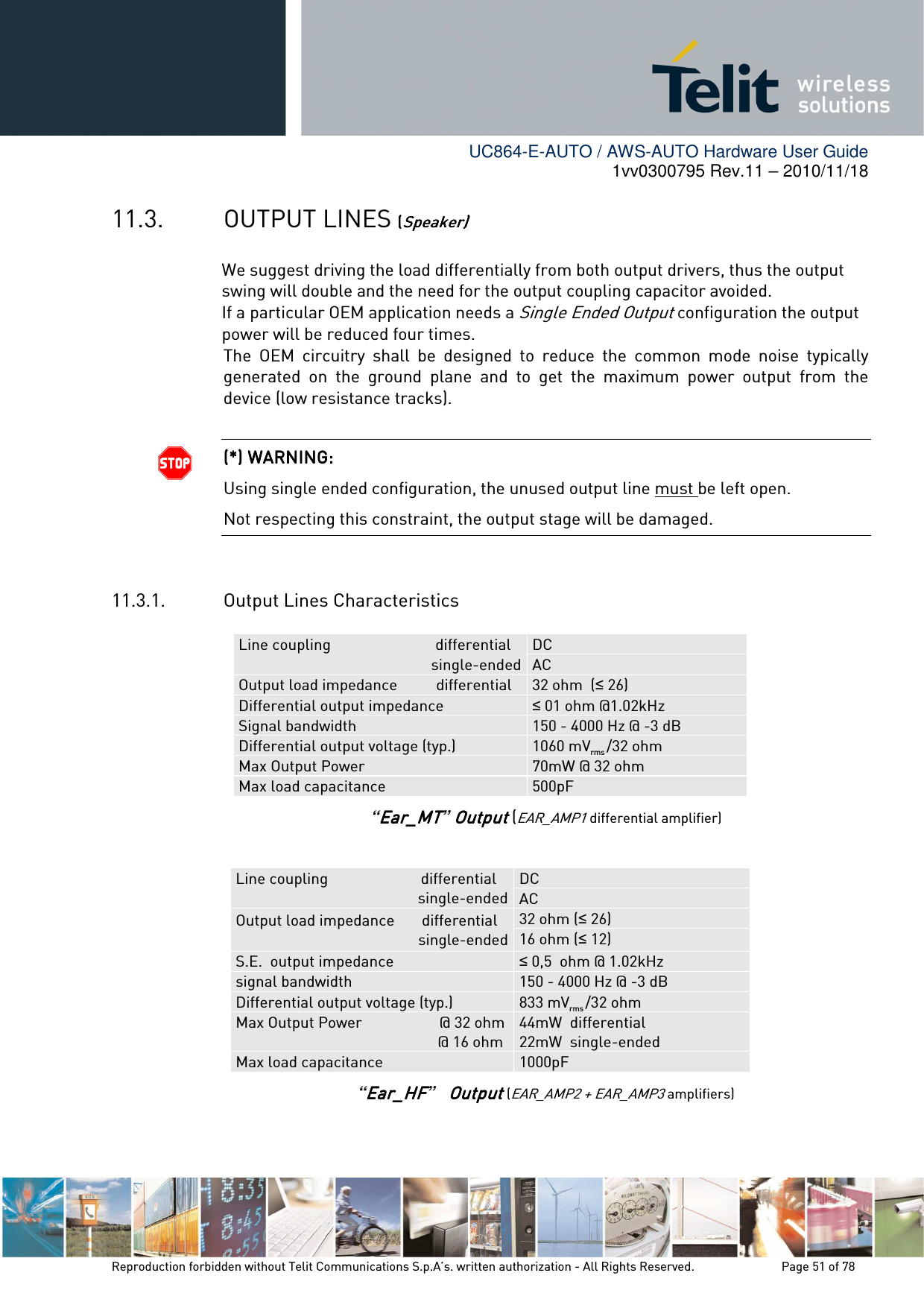
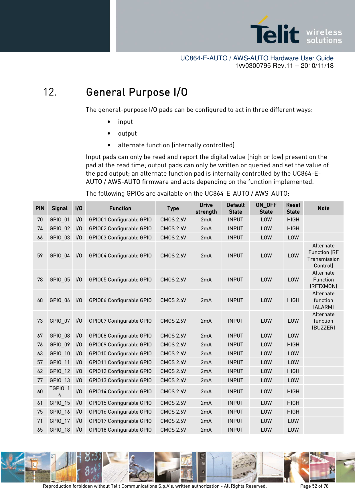
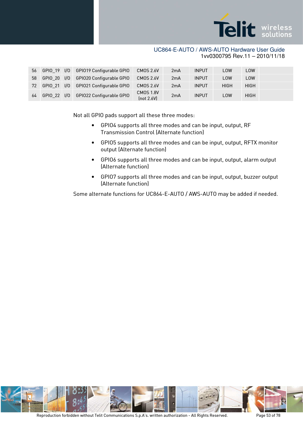
Users guide


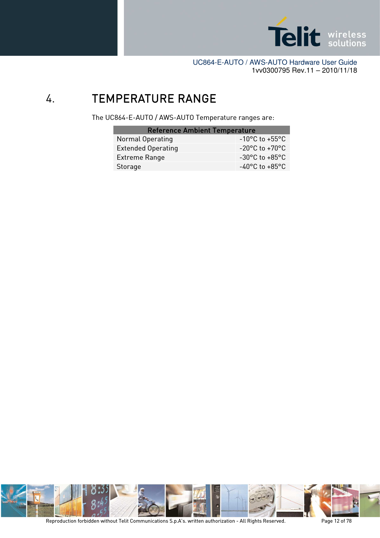


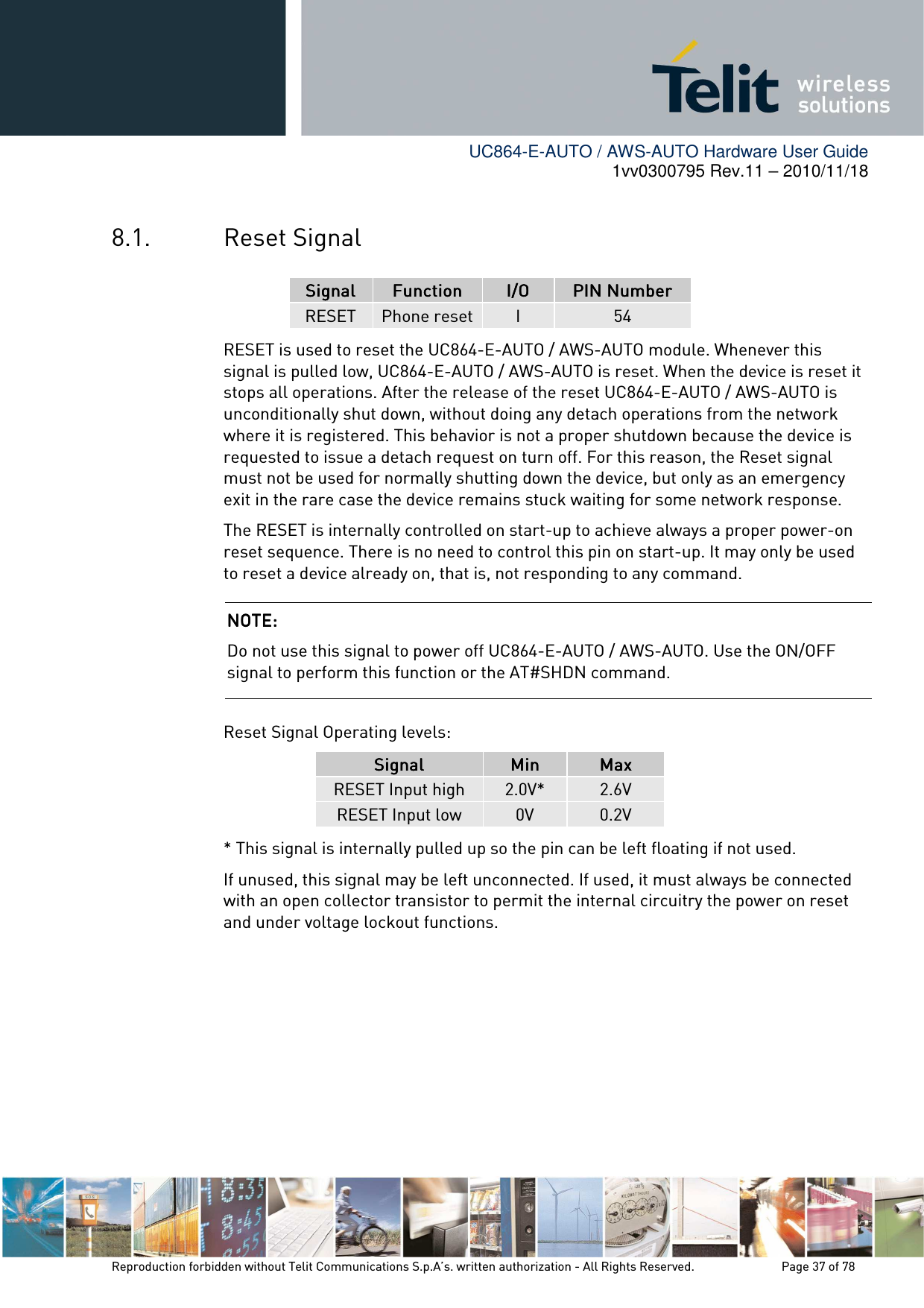
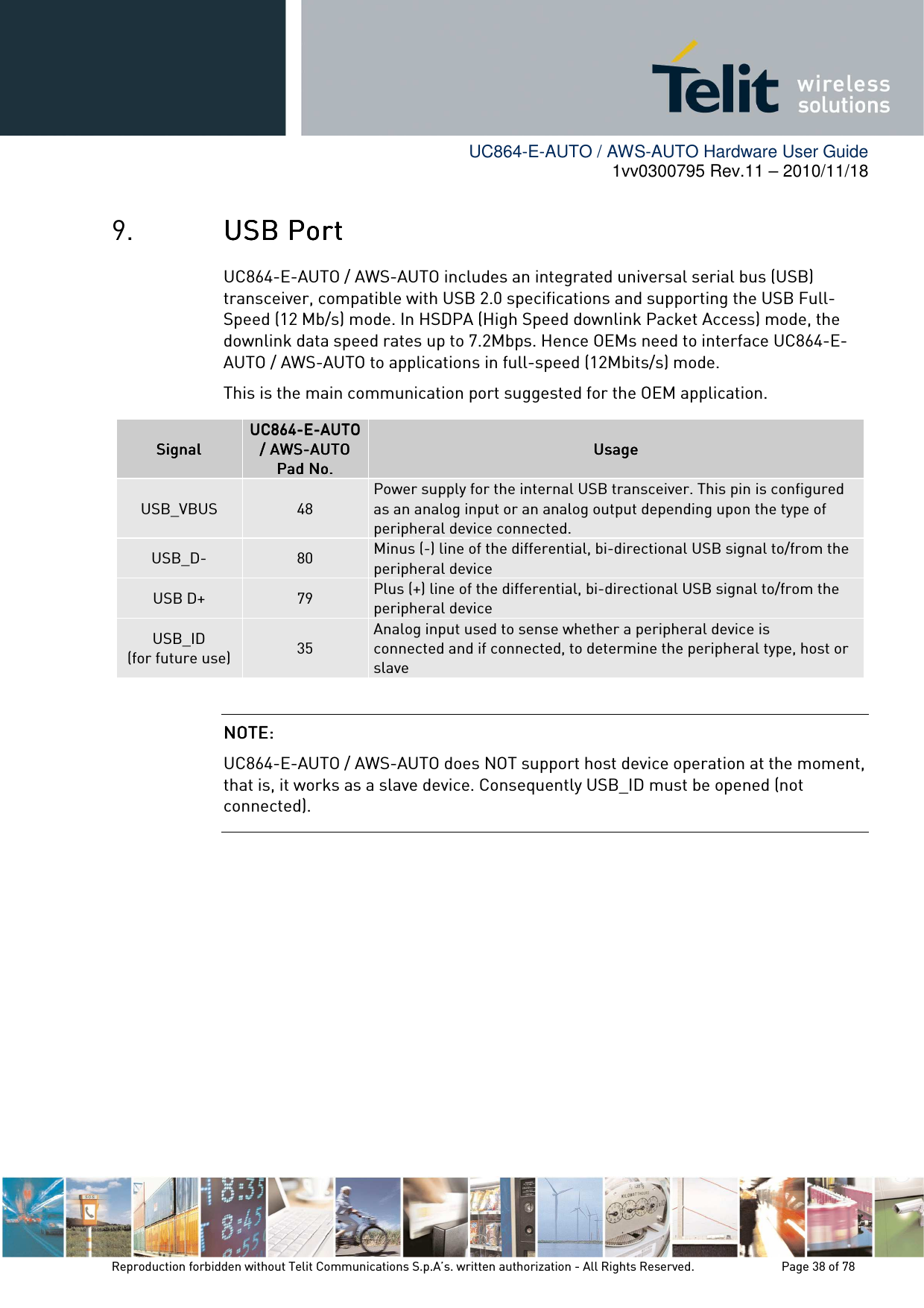
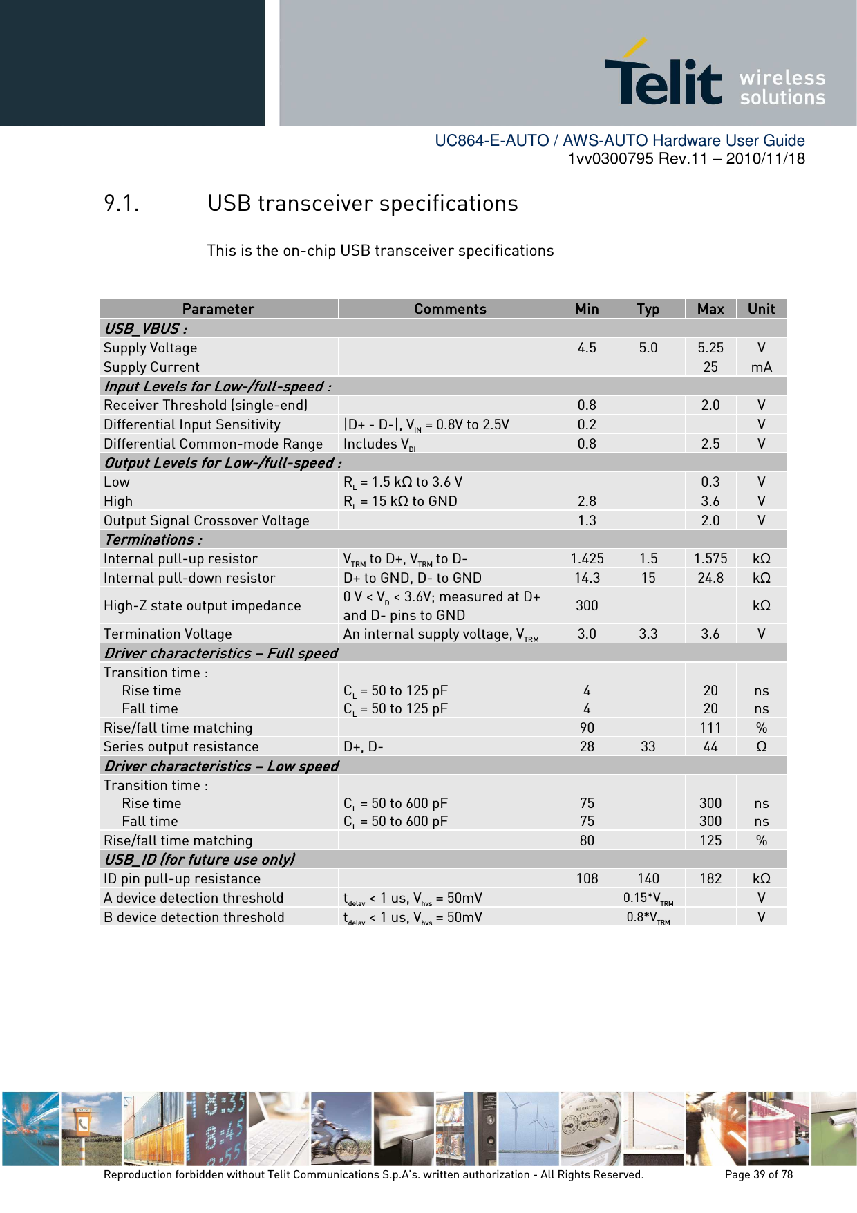
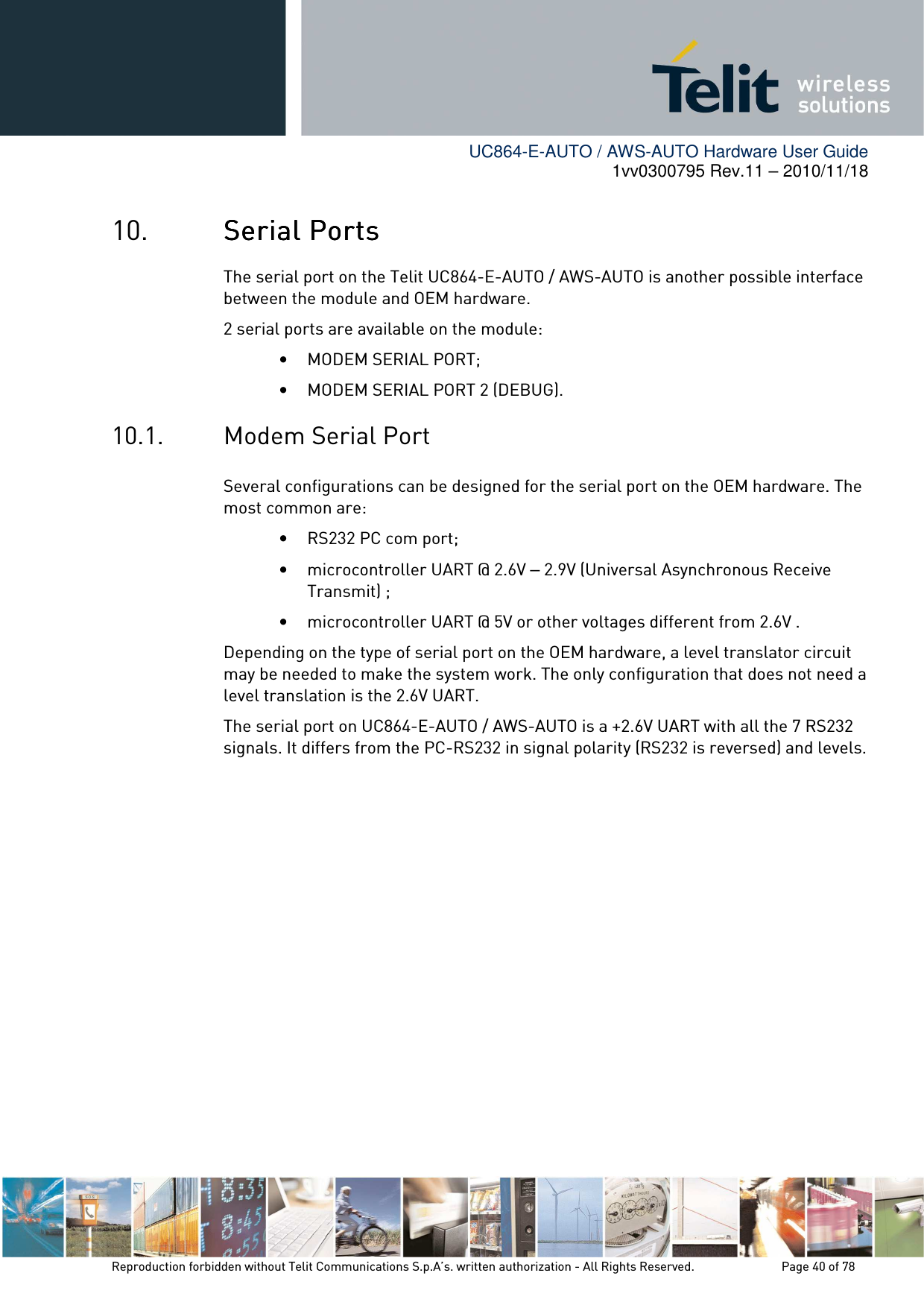
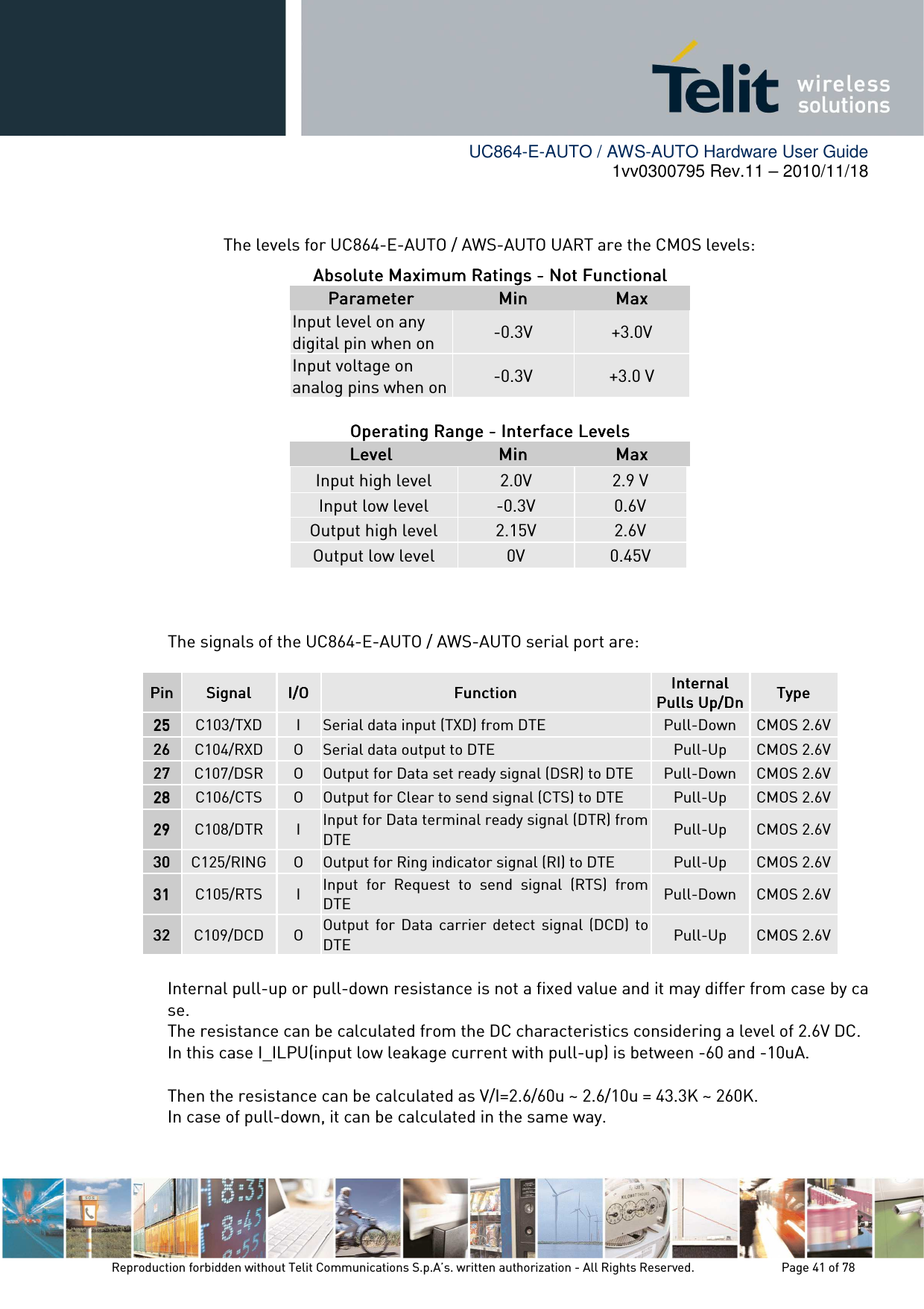
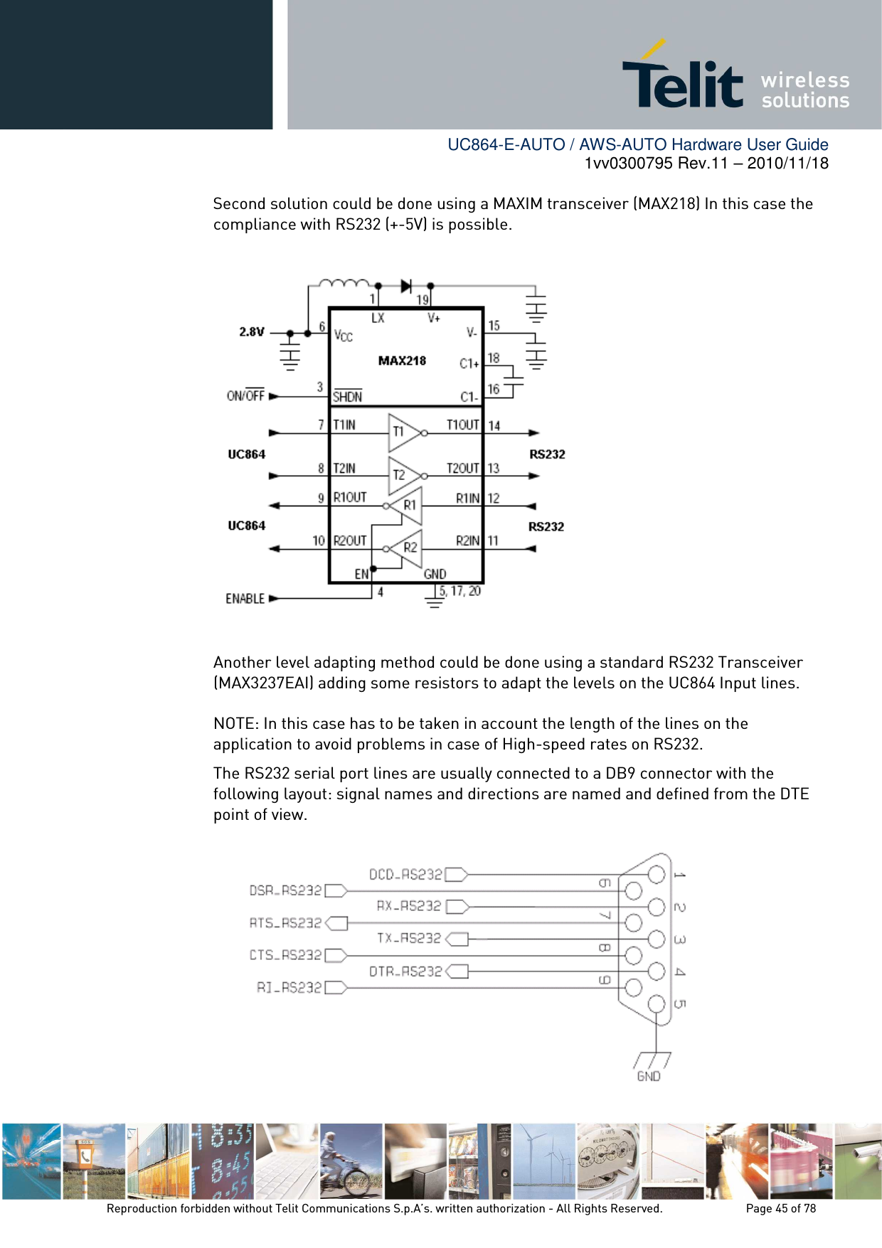

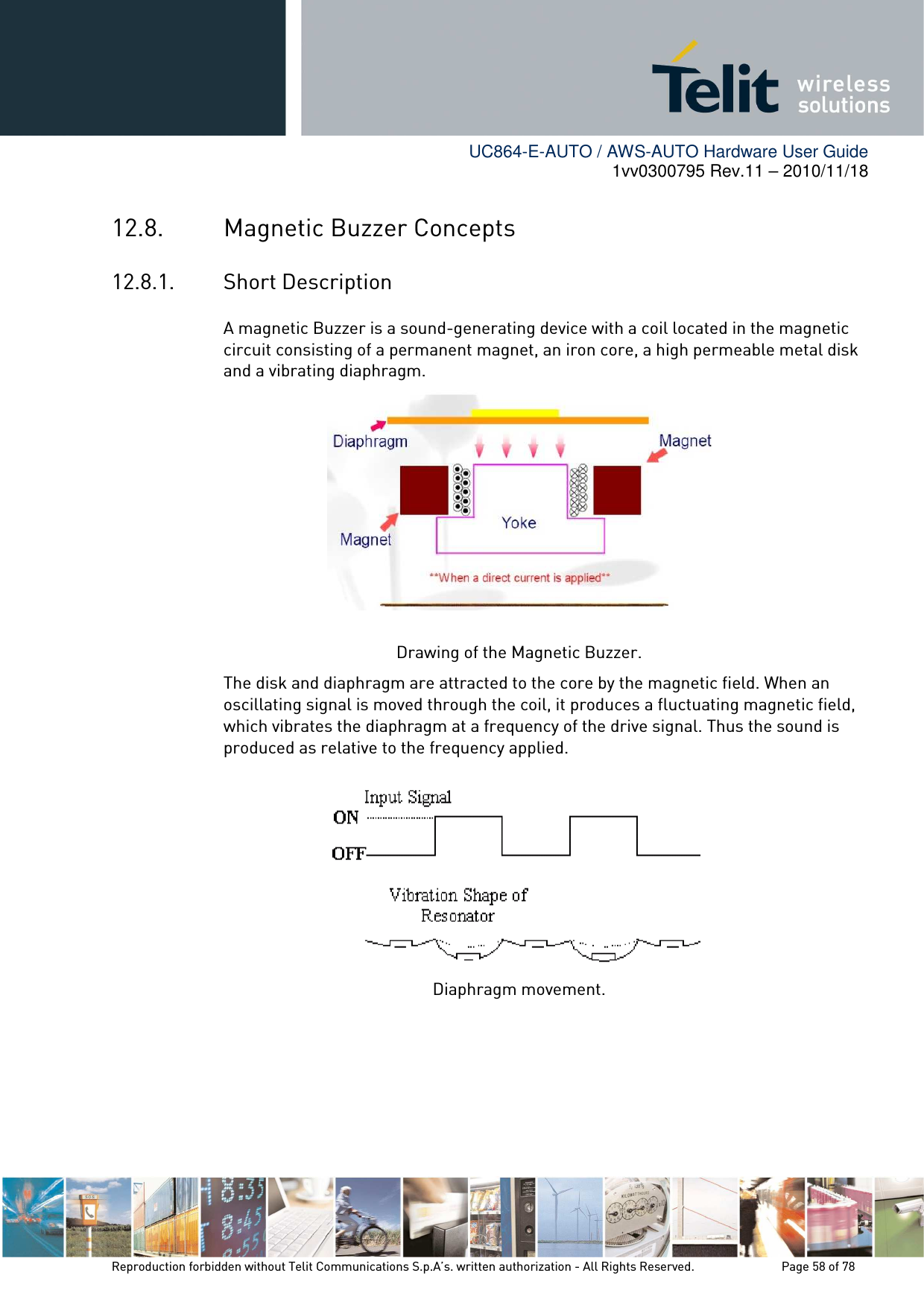

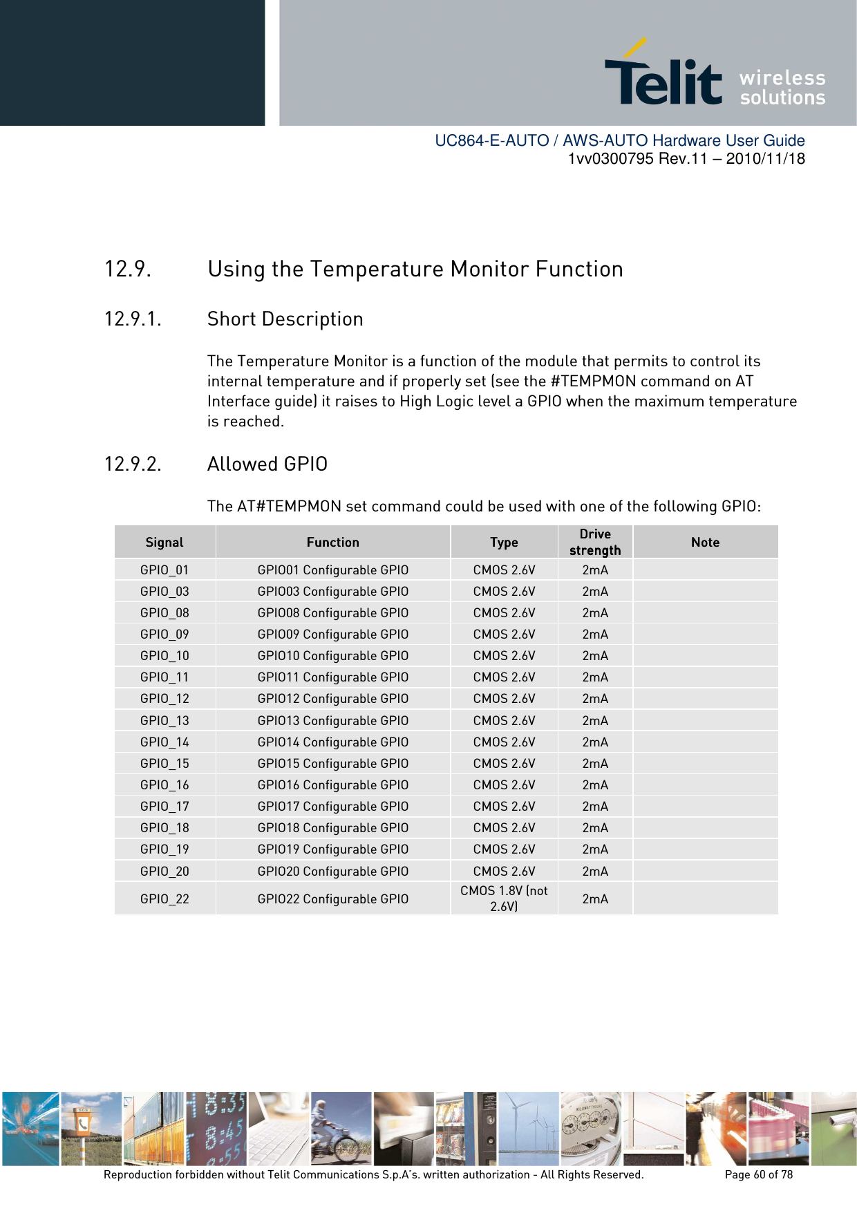
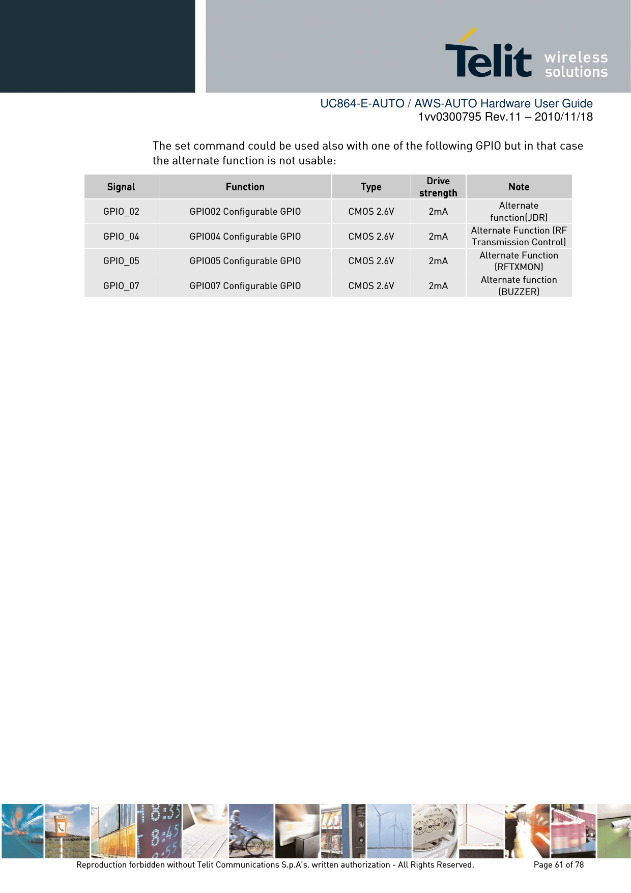
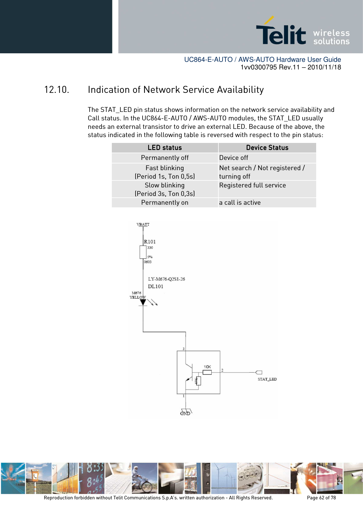
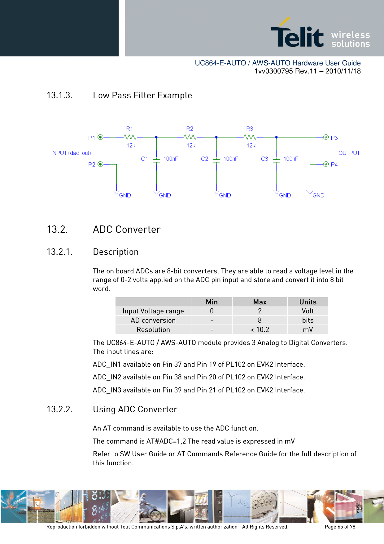
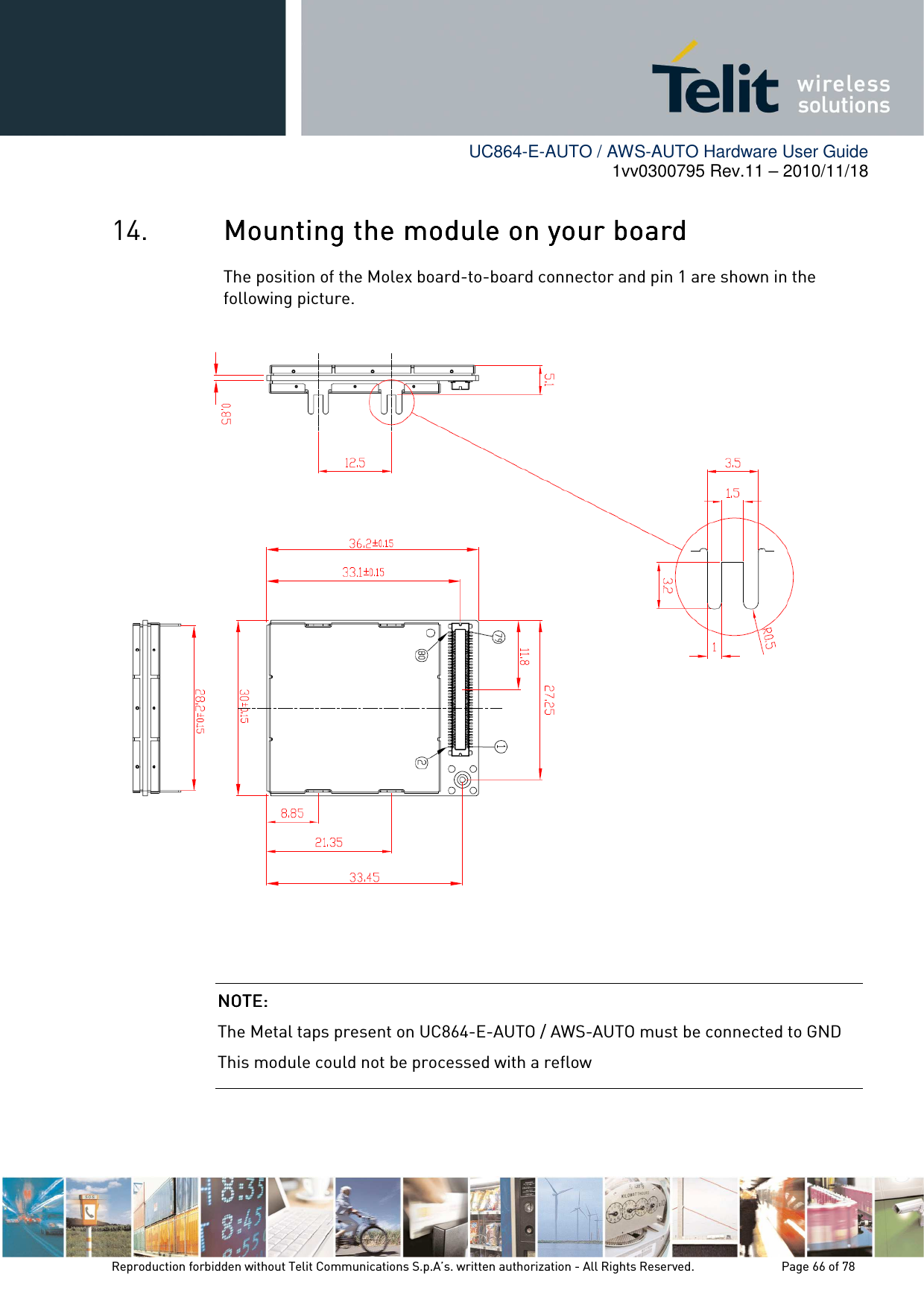
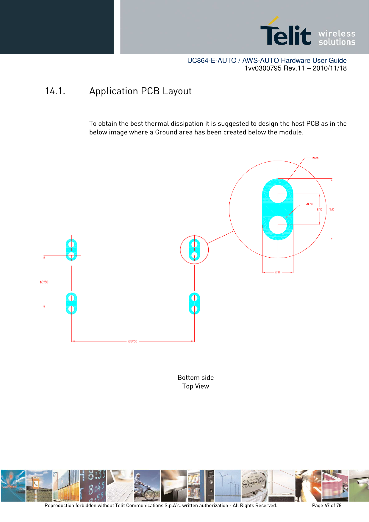
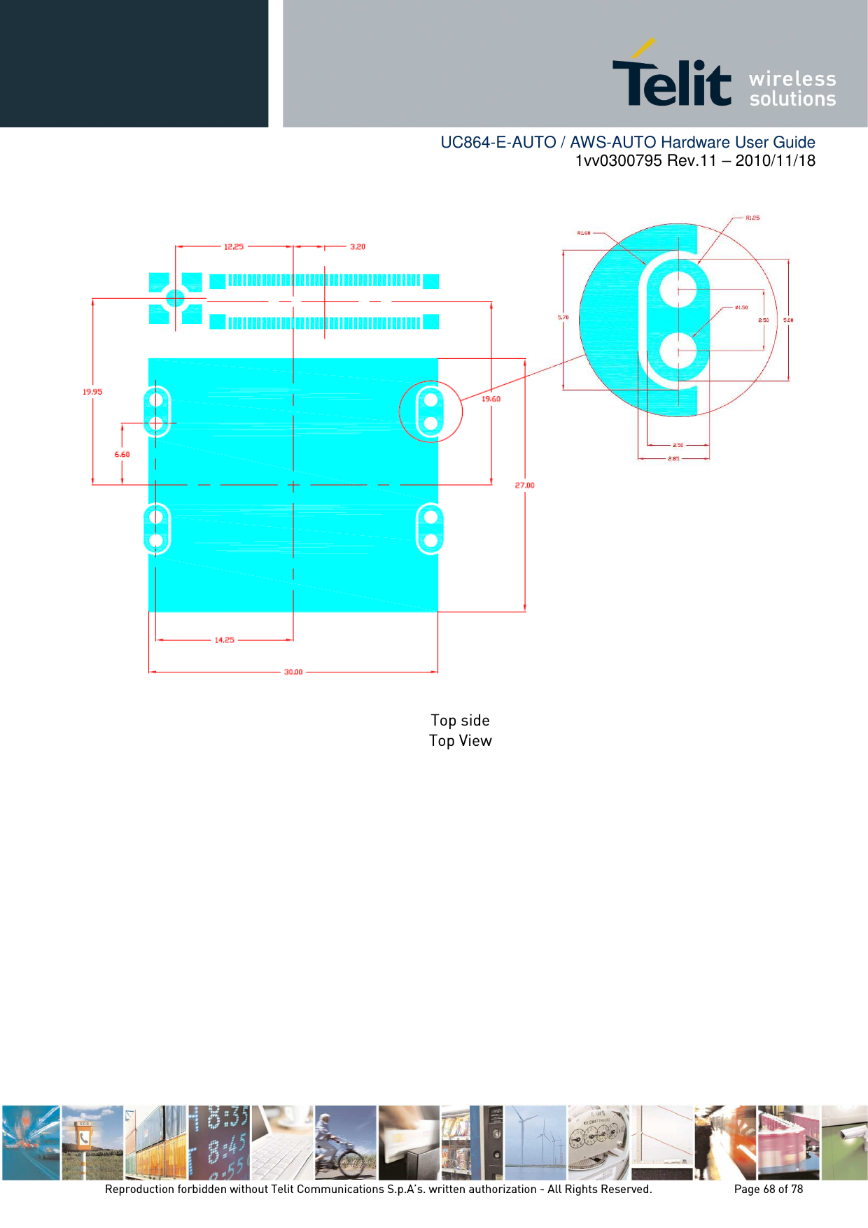
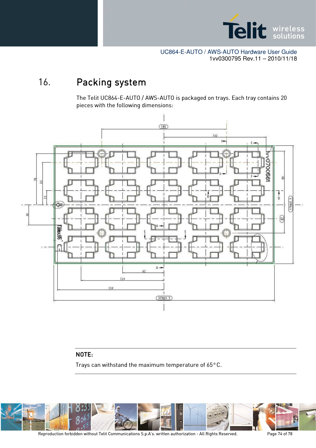
![UC864-E-AUTO / AWS-AUTO Hardware User Guide 1vv0300795 Rev.11 – 2010/11/18 Reproduction forbidden without Telit Communications S.p.A’s. written authorization - All Rights Reserved. Page 64 of 78 13. DAC and ADC sectionDAC and ADC sectionDAC and ADC sectionDAC and ADC section 13.1. DAC Converter 13.1.1. Description The UC864-E-AUTO / AWS-AUTO module provides a Digital to Analog Converter. The signal (named DAC_OUT) is available on pin 40 of the UC864-E-AUTO / AWS-AUTO module and on pin 17 of PL102 on EVK2 Board (KS101C). The on board DAC is a 16-bit converter, able to generate an analogue value based on a specific input in the range from 0 up to 65535 but recalibrated in the range from 0 to 1023. However, an external low-pass filter is necessary. MinMinMinMin MaxMaxMaxMax UnitsUnitsUnitsUnits Voltage range (filtered) 0 2.6 Volt Range 0 1023 Steps The precision is 1023 steps, so if we consider that the maximum voltage is 2V, the integrated voltage could be calculated with the following formula: Integrated output voltage = 2 * value / 1023 DAC_OUT line must be integrated (for example with a low band pass filter) in order to obtain an analog voltage. 13.1.2. Enabling DAC An AT command is available to use the DAC function. The command is:AT#DAC[=<enable>[,<value>]] <value> - scale factor of the integrated output voltage (0..1023 - 10 bit precision) it must be present if <enable>=1 Refer to SW User Guide or AT Commands Reference Guide for the full description of this function. NOTE: NOTE: NOTE: NOTE: The DAC frequency is selected internally. D/A converter must not be used during POWERSAVING.](https://usermanual.wiki/Telit-Communications-S-p-A/UC864AWA.Users-guide/User-Guide-1379663-Page-64.png)