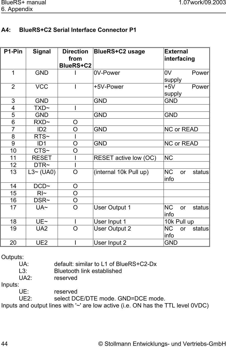
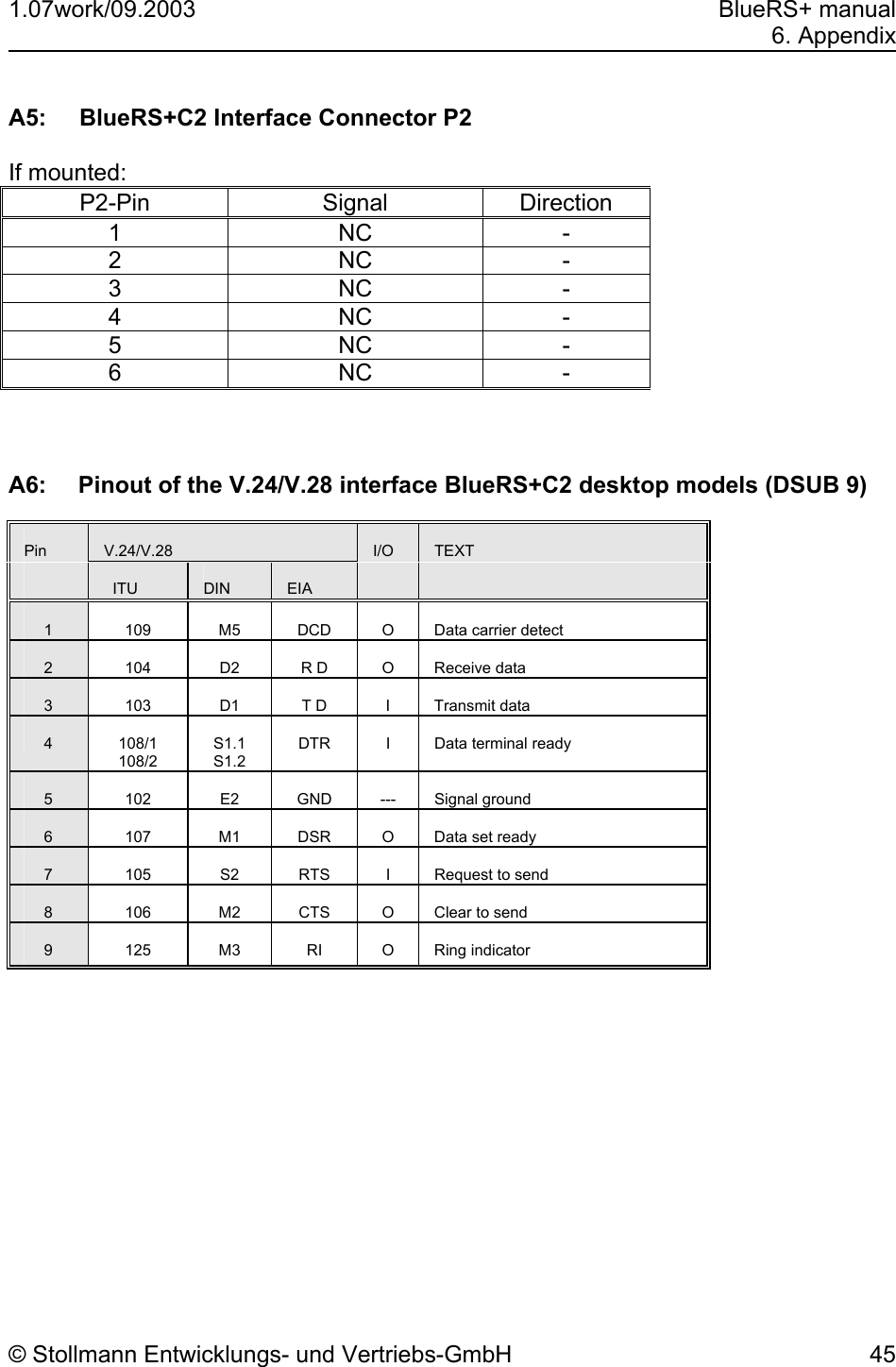
Telit Wireless Solutions BLUERSC2 Bluetooth Serial Modem User Manual user manual
Stollmann E+V GmbH Bluetooth Serial Modem user manual
UserManual.wiki
>
Telit Wireless Solutions
>
BLUERSC2 User Manual
Users Manual
Navigation menu
Upload a User Manual
Namespaces
Wiki Guide
HTML
PDF
Info
Views
User Manual
Discussion / Help
Navigation
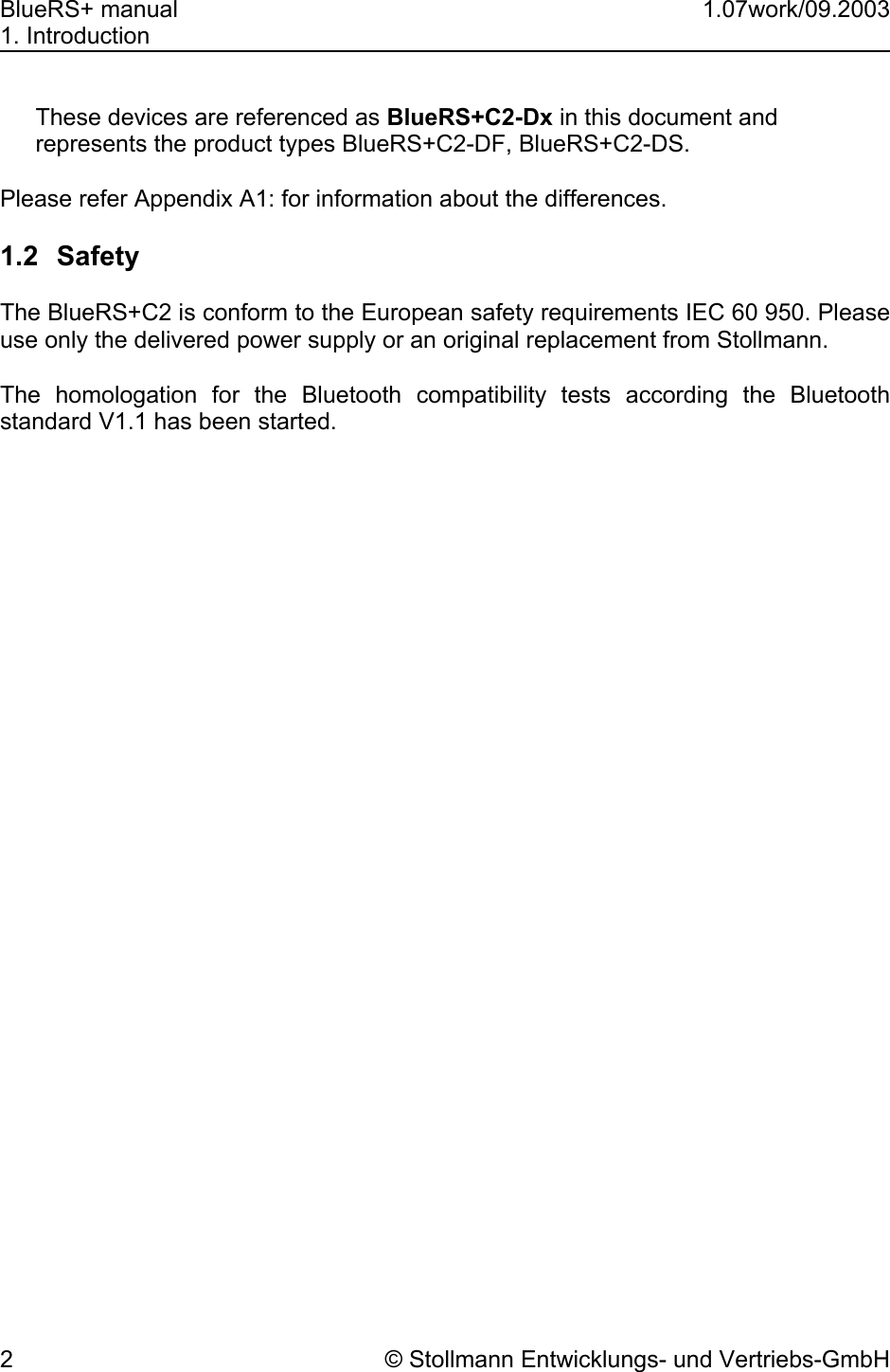

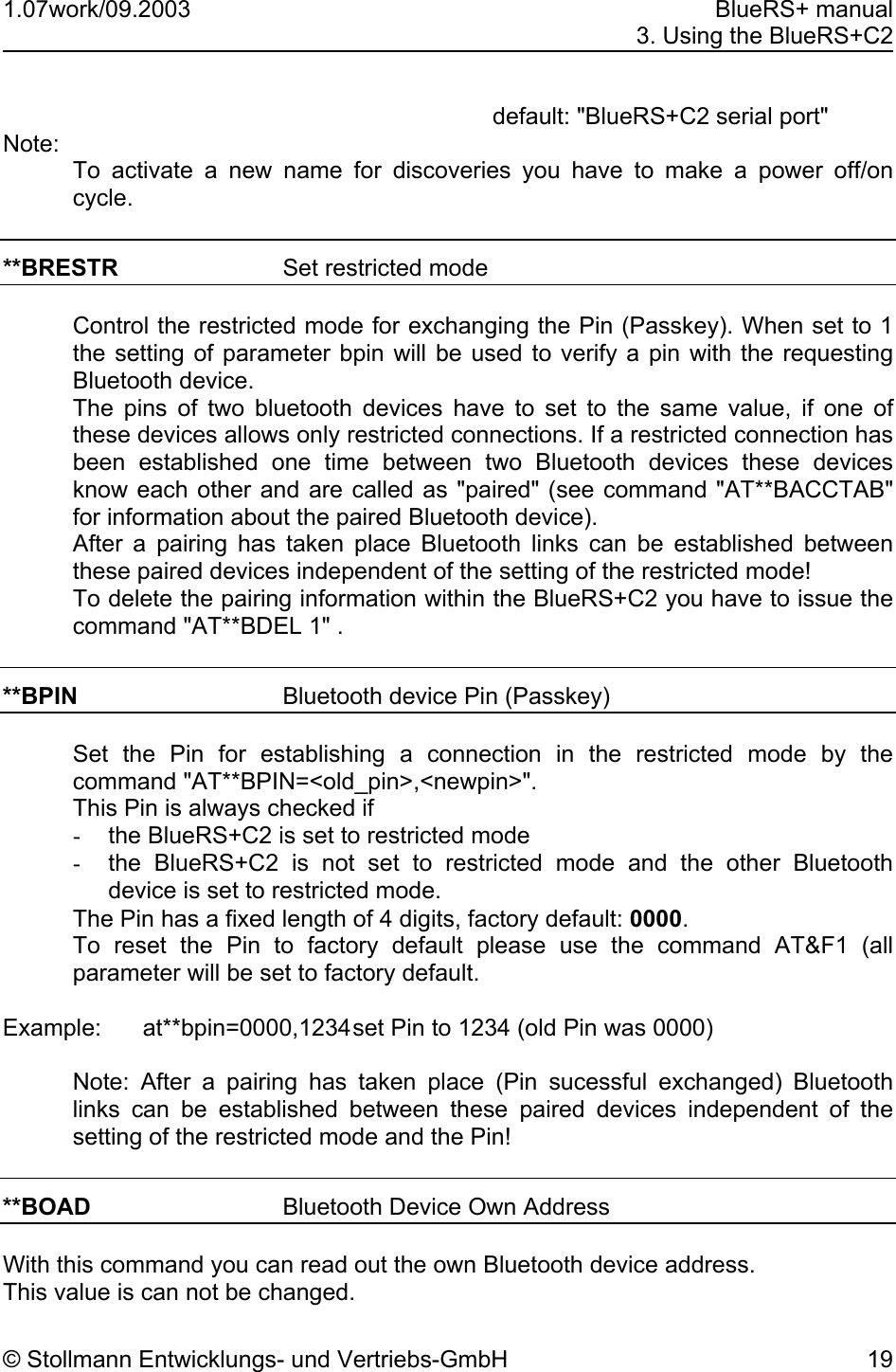

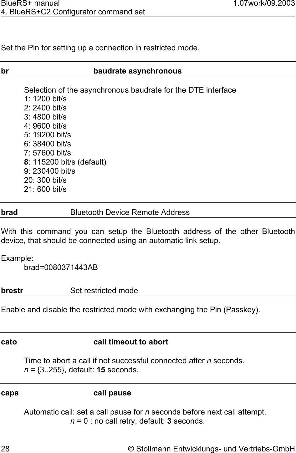
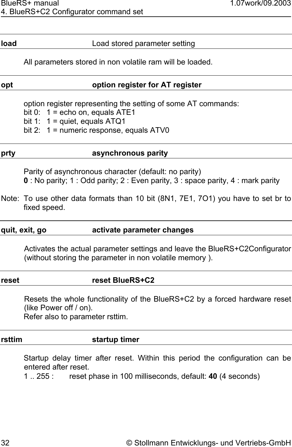
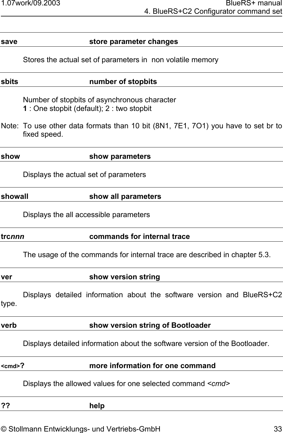
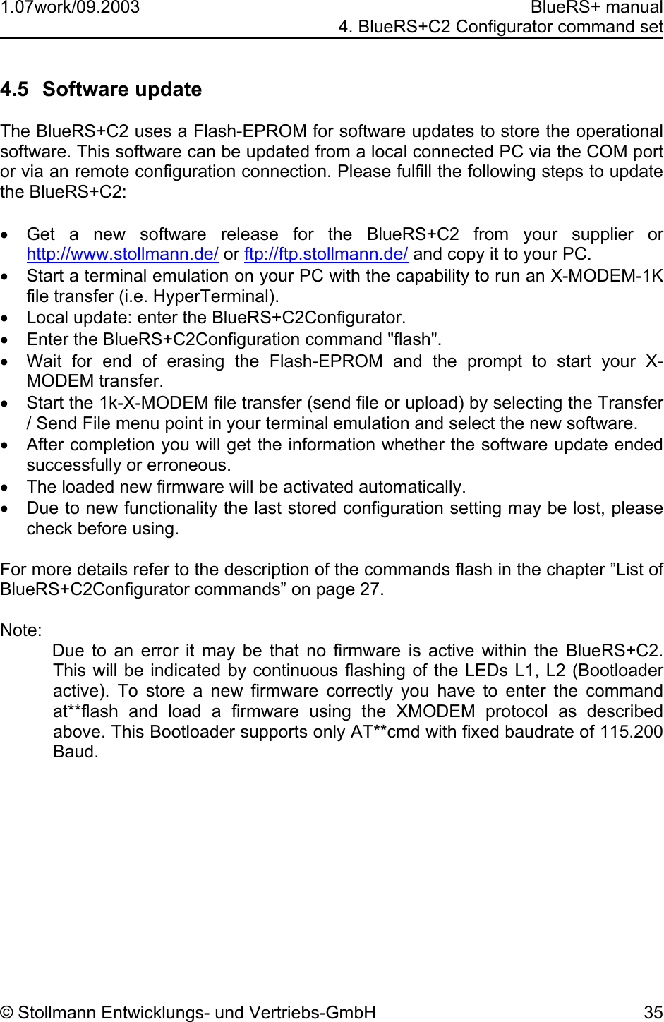
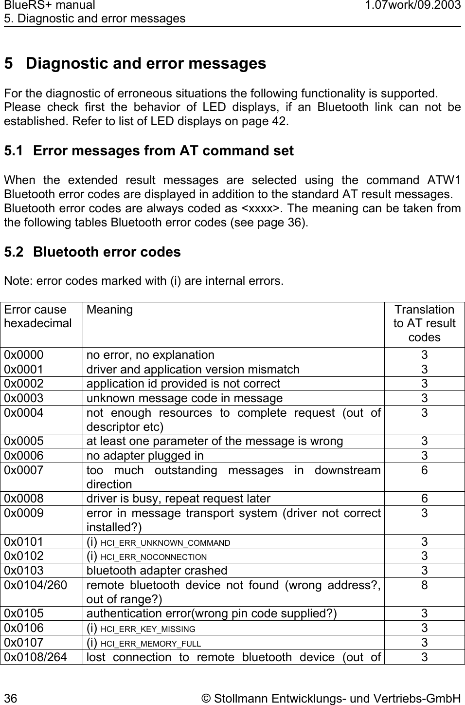
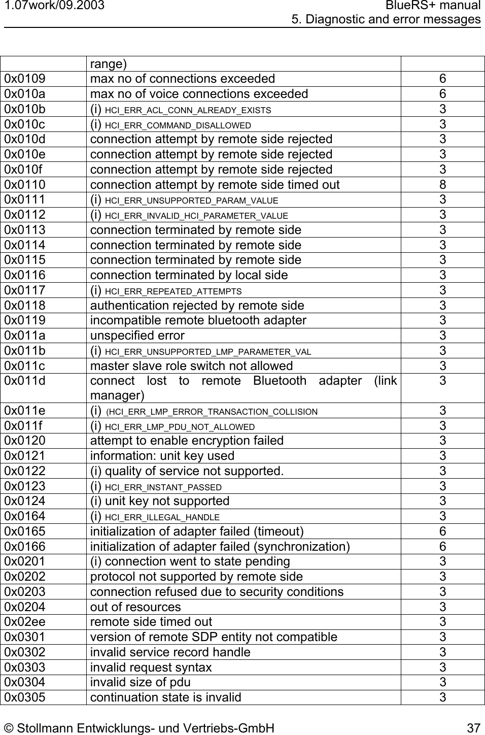
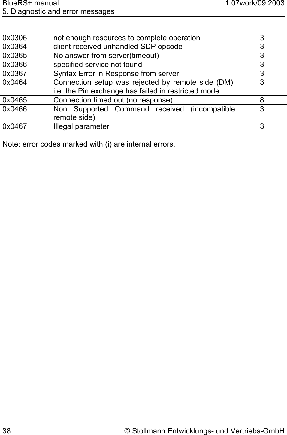
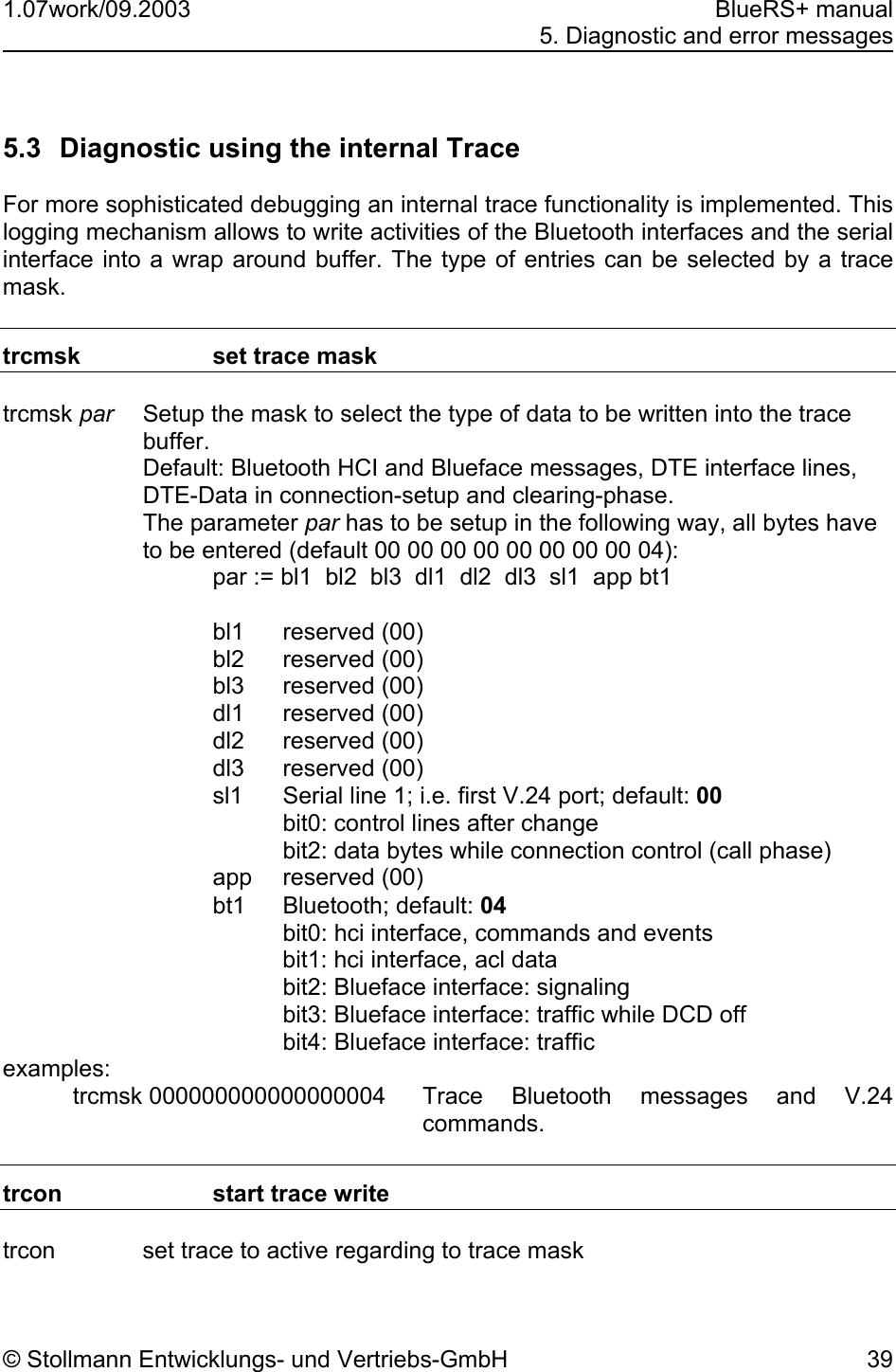
![1.07work/09.2003 BlueRS+ manual 4. BlueRS+C2 Configurator command set © Stollmann Entwicklungs- und Vertriebs-GmbH 27 4.4 List of BlueRS+C2Configurator commands The BlueRS+C2Configurator commands typed in must have the correct syntax and be complete, including all blanks. Capital/small letter use is not important. The entry is not case sensitive. The bolded values are factory defaults. The usage is: [?]<command>[=parameter] Example to set the baudrate to 9600 baud: br=4 Example to show the selected baudrate: br Example to show all selectable baudrates: ?br To get an overview about the commands of your BlueRS+C2 some major commands here as a preview: show show the usually used parameter showall show all changeable parameter quit leave BlueRS+C2Configurator help show all available commands defa 1 setup factory default parameter set save store parameter non volatile at.sx AT command parameter set AT command set only: Handle AT specific settings. Show and change AT S registers by entering the new value. at.s0 show setting of S0-Register at.s0=1 set Register S0 to 1 boad Bluetooth Device Own Address With this command you can read out the own Bluetooth device address. (read only) Example: boad bpin Bluetooth device Pin (Passkey)](https://usermanual.wiki/Telit-Wireless-Solutions/BLUERSC2/User-Guide-354189-Page-31.png)