Telit Wireless Solutions BLUERSC2 Bluetooth Serial Modem User Manual user manual
Stollmann E+V GmbH Bluetooth Serial Modem user manual
Users Manual

BlueRS+C2
Bluetooth Serial Adapter
User manual
Version 1.07work
Date 09.2003
© Stollmann Entwicklungs- und Vertriebs- GmbH
Component name: BlueRS+C2 User manual
Article No.: 621-51809

BLUERS+ manual 1.07work/09.2003
Exclusion of Liability
© Stollmann Entwicklungs- und Vertriebs-GmbH
Exclusion of Liability
The present manual by Stollmann Entwicklungs- und Vertriebs-GmbH (hereinafter
referred to as Stollmann) reflects the present state of the art of the products
described therein. We have endeavored to give a description that is as complete and
clear as possible in order to make work with our products as easy as possible for
you. All the same, the manual may contain technical inaccuracies and typing errors.
As a result of the rapid advance in the art, we must also reserve the right to
incorporate technical alterations and developments without separate advance notice.
That is why Stollmann does not give any warranty for the contents of the manual and
for its continuing applicability.
Nor is Stollmann liable for any loss of information or any incorrect use of information
that might result from consultation of the manual. Particularly, Stollmann is not liable
for damage, nor indirect damage (including damage caused by financial loss, delays
affecting business transactions or interruptions of business and similar
consequences), arising from the use or improper use of this manual, not even in the
case where it was pointed out to Stollmann or an agent of Stollmann that such
damage might be sustained. This does not, of course, affect our legal liability for
damages based on any intent or gross negligence.
With respect to the data given in this manual, Stollmann does not warrant the non-
existence of industrial property rights (trademarks, patents, utility models, etc.). Nor
are trade names, brand names, company names and product names in general use
but are subject to the relevant trademark, patent, utility model and registered design
rights.
The information must neither in whole nor even in part be copied, translated,
reproduced or in any other way transferred to or stored on any electronic medium or
other machine.
The purchase and use of software are governed by the General Conditions of
Delivery and Payment as well as the Terms of License of Stollmann.
If any of the provisions on the exclusion of tina is a registered liability or on use are
or become ineffective for statutory reasons, this will not affect the other provisions.
Trademark of Stollmann Entwicklungs- und Vertriebs-GmbH.

1.07work/09.2003 BlueRS+ manual
Table of Contents
© Stollmann Entwicklungs- und Vertriebs-GmbH i
Table of contents
1 Introduction ..................................................................................................... 1
1.1 Product description ......................................................................................... 1
1.2 Safety.............................................................................................................. 2
1.3 Hints for using the BlueRS+C2 in the United States, ...................................... 3
2 Installation....................................................................................................... 4
2.1 Contents ......................................................................................................... 4
2.2 Installation procedure...................................................................................... 4
2.3 Displays and control elements BlueRS+C2-MF5 desktop model.................... 5
3 Using the BlueRS+C2..................................................................................... 6
3.1 Automatic connection establishment............................................................... 7
3.2 AT command set for BlueRS+C2.................................................................... 9
3.2.1 Bluetooth specific AT commands ........................................................... 16
3.2.2 AT command S register set.................................................................... 21
3.2.3 AT result codes ...................................................................................... 21
3.3 Cable replacement........................................................................................ 22
3.4 Table of coding of Bluetooth services ........................................................... 23
4 BlueRS+C2 Configurator command set........................................................ 24
4.1 Configuring the BlueRS+C2 after power on.................................................. 24
4.2 Configuring the BlueRS+C2 with AT commands .......................................... 25
4.3 Remote Configuration using the TA+Configurator commands...................... 25
4.4 List of BlueRS+C2Configurator commands .................................................. 27
4.5 Software update............................................................................................ 35
5 Diagnostic and error messages .................................................................... 36
5.1 Error messages from AT command set ........................................................ 36

BlueRS+ manual 1.07work/09.2003
Table of contents
ii © Stollmann Entwicklungs- und Vertriebs-GmbH
5.2 Bluetooth error codes.................................................................................... 36
5.3 Diagnostic using the internal Trace............................................................... 39
6 Appendix....................................................................................................... 41
A1: Technical data BlueRS+C2........................................................................... 41
A2: LED displays BlueRS+C2 desktop models ................................................... 42
A3: Mechanical dimensions of the BlueRS+C2 module ...................................... 43
A4: BlueRS+C2 Serial Interface Connector P1 ................................................... 44
A5: BlueRS+C2 Interface Connector P2 ............................................................. 45
A6: Pinout of the V.24/V.28 interface BlueRS+C2 desktop models (DSUB 9) .... 45

1.07work/09.2003 BlueRS+ manual
1. Introduction
© Stollmann Entwicklungs- und Vertriebs-GmbH 1
1 Introduction
We are very pleased to see that you have bought a Stollmann product and would like
to express our appreciation.
This documentation is valid for the following models of the BlueRS+C2 product
family
• BlueRS+C2-MF5 (plug on module, antenna internal, 5V DC)
• BlueRS+C2-MF3 (plug on module, antenna internal, 3.3V DC) on request
• BlueRS+C2-MS5 (plug on module, antenna external, 5V DC) on request
• BlueRS+C2-MS3 (plug on module, antenna external, 3.3V DC) on request
• BlueRS+C2-DF (desktop model, antenna internal)
• BlueRS+C2-DS (desktop model, antenna external) on request
• Software versions V1.124.003 or later
1.1 Product description
The BlueRS+C2 is an Bluetooth adapter with the following functions.
• The BlueRS+C2 connects devices with a serial port to any Bluetooth link. It
gives access to other devices situated in the same Bluetooth area (piconet).
• Data can be transmitted with the following rates:
- limited by the baudrate of the serial link from 1200 up to 230400 baud.
• The connected serial device can drive the BlueRS+C2 by using
- asynchronous AT commands
- automatic connection setup
The following profiles are supported:
• One serial profile for transparent data communication through the Bluetooth link.
• A second serial profile for management access from another Bluetooth device
using a Bluetooth link.
BlueRS+C2 may be used in two product versions:
• The BlueRS+C2 module may be integrated into different devices and connects
them with the Bluetooth interface via a serial TTL/CMOS compatible interface.
These modules are referenced as BlueRS+C2-Mxx in this document and
represents the product types BlueRS+C2-MF5, BlueRS+C2-MF3, BlueRS+C2-
MS5, BlueRS+C2-MS3.
• The BlueRS+C2 Desktop device is an external device that connects the terminal
equipment with the Bluetooth interface via a serial V.24 / RS-232 interface.

BlueRS+ manual 1.07work/09.2003
1. Introduction
2 © Stollmann Entwicklungs- und Vertriebs-GmbH
These devices are referenced as BlueRS+C2-Dx in this document and
represents the product types BlueRS+C2-DF, BlueRS+C2-DS.
Please refer Appendix A1: for information about the differences.
1.2 Safety
The BlueRS+C2 is conform to the European safety requirements IEC 60 950. Please
use only the delivered power supply or an original replacement from Stollmann.
The homologation for the Bluetooth compatibility tests according the Bluetooth
standard V1.1 has been started.

1.07work/09.2003 BlueRS+ manual
1. Introduction
© Stollmann Entwicklungs- und Vertriebs-GmbH 3
1.3 Hints for using the BlueRS+C2 in the United States,
This device complies with Part 15 of the FCC Rules and with RSS-210 of Industry
Canada.
Operation is subject to the following two conditions:
1. This device may not cause harmful interference
2. This device must accept any interference received, including interference
that may cause undesired operation.
The radiated output power of BlueRS+C2 is far below the FCC radio frequency
exposure limits. Nevertheless, the BlueRS+C2 shall be used in such a manner that
the potential for human contact during normal operation is minimized.
This equipment has been tested and found to comply with the limits for a Class B
digital device, pursuant to Part 15 of the FCC Rules. These limits are designed to
provide reasonable protection against harmful interference in a residential
installation. This equipment generates, uses and can radiate radio frequency energy
and, if not installed and used in accordance with the instructions, may cause harmful
interference to radio communications. However, there is no guarantee that
interference will not occur in a particular installation. If this equipment does cause
harmful interference to radio or television reception, which can be determined by
turning the equipment off and on, the user is encouraged to try to correct the
interference by one or more of the following measures:
• Reorient or relocate the receiving antenna.
• Increase the separation between the equipment and receiver.
• Connect the equipment into an outlet on a circuit different from that to which the
receiver is connected.
• Consult the dealer or an experienced radio/TV technician for help.
Warning:
Changes or modifications made to this equipment not expressly approved by
Stollmann E+V GmbH may void the FCC authorization to operate this equipment

BlueRS+ manual 1.07work/09.2003
2. Installation
4 © Stollmann Entwicklungs- und Vertriebs-GmbH
2 Installation
2.1 Contents
This packet contains the following items:
• Bluetooth Serial adapter BlueRS+C2
• Mains plug power supply adapter (only BlueRS+C2-Dx)
• DTE interface serial cable (only BlueRS+C2-Dx)
• This user manual
2.2 Installation procedure
The following installation procedure is typical for the desktop model BlueRS+C2-Dx.
For all plug in modules the installation is dependent on the overall system and has to
be referred there.
Desktop model only:
To start using the BlueRS+C2-Dx, please follow these steps:
• Connect the serial port (DTE) of the BlueRS+C2 to the serial port (COM-port) of a
PC or other serial terminal equipment by using the supported DTE interface serial
cable.
Please make sure that the COM-port of the PC is not used for other purposes or
by other communication programs.
• Connect the power supply to a standard AC outlet. Please reference to page 5 for
selecting the correct plug for interfacing.
• The green LED on the BlueRS+C2-Dx front panel will come on to indicate that
the device has been power up. After some seconds the green LED will start
blinking to indicate power save mode.
• Optionally: Configure the BlueRS+C2-Dx Bluetooth interface if needed.
Configuration is required especially if you want to automatically connect to
another Bluetooth device (set up the remote Bluetooth address).
The BlueRS+C2 is now ready for use with Bluetooth links, please refer to the next
chapter for the configuration to use the terminal equipment together with the
BlueRS+C2.
1.07work/09.2003 BlueRS+ manual
2. Installation
© Stollmann Entwicklungs- und Vertriebs-GmbH 5
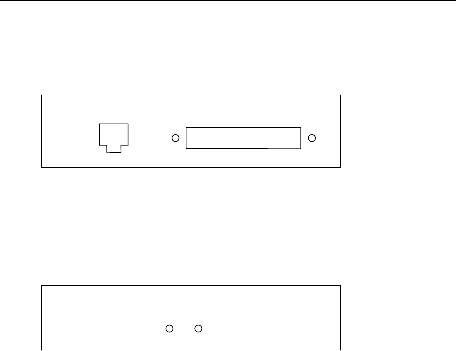
2.3 Displays and control elements BlueRS+C2-MF5 desktop model
For interfacing the module version please refer to the appendix.
At the back of the BlueRS+C2 you will find the connectors for the following devices:
Fig. 2: Back view of the desktop model BlueRS+C2
PWR: external power supply (5V DC)
DTE: V.24 interface for DTE, i.e. a PC
You can control the status of the BlueRS+C2 via two LEDs at the front side.
Fig. 3: Front view of the desktop model BlueRS+C2
Both of the LEDs, L1 (green) and L2 (yellow), show the overall status of the
BlueRS+C2 in coded form. The following list describes the view for an error free
power on sequence of the BlueRS+C2.
Status L1 L2
1. Power-On-Phase, Bootloader, wait Θ Θ (about 2 sec)
2. Power-On-Phase, Initializing, wait Θ O (about 10 sec)
3. Ready, Initialization ok ⊗ O
4. Ready, Initialization ok, power save ∅ O
5. Connected, Bluetooth link established ⊗ ⊗
LED Legend: ⊗ On, O Off
Θ Continuously blinking, ∅ flashing
A complete list you can find in the appendix "LED displays".
DTE
PWR
L1 L2

BlueRS+ manual 1.07work/09.2003
3. Using the BlueRS+C2
6 © Stollmann Entwicklungs- und Vertriebs-GmbH
3 Using the BlueRS+C2
Before using the BlueRS+C2 the address of another Bluetooth device has to be
selected - if not predefined by factory – that shall be the communication partner in
the Bluetooth link.
The compatible devices can be scanned using the configuration command "bdinq".
From that list one Bluetooth device has to selected.
If you are using an automatic connecting mode that Bluetooth address has to be
entered and stored using the configuration command "brad" (see
BlueRS+C2Configurator activation on page 24).
You can select different operation modes for the BlueRS+C2. These operating
modes are used to control Bluetooth links and to configure the BlueRS+C2.
Supported operating modes:
• Automatic connecting deriving from DTR or always connected.
• Automatic accepting of incoming connections.
• Asynchronous mode for devices that need the AT command set.
You can configure the BlueRS+C2 in the following ways:
• by using BlueRS+C2Configuration commands entered by the locally connected
PC.
• by using the AT command set entered by the locally connected PC.
• by using BlueRS+C2Configuration commands entered via the Bluetooth link
(remote configuration).

1.07work/09.2003 BlueRS+ manual
3. Using the BlueRS+C2
© Stollmann Entwicklungs- und Vertriebs-GmbH 7
3.1 Automatic connection establishment
Automatic connection establishment is available in the following modes:
• An automatic connection will be initiated when control line DTR is on.
• An automatic connection will be initiated when transmit data is received from the
DTE device. All data received before the Bluetooth connection is established will
be buffered inside the BlueRS+C2 and automatically sent via the Bluetooth link.
• An Automatic connection will be initiated independent of any status line –
automatically after power up and initialization.
• No connection establishment initiated by this module. Bluetooth connection
requests from other Bluetooth devices will be automatically accepted (if
compatible).
To enable automatic call you have to set BlueRS+C2Configuration parameter "cmds"
to 6, 7, 8 or 13 (see below).
An established connection will be indicated by a status line (default: DCD). See also
configuration commands "cdcd" and "cdtr".
If a connection cannot be established successfully an automatic retry will be started.
The duration of trying to establish the connection and the pause for next retry can be
configured.
The Bluetooth device to be accessed is taken from the parameter "brad", it has to be
set up to the Bluetooth device address of the remote Bluetooth device. Additionally
the server channel has to be set up if not fitting to the default (1), see parameter
brsch.
cmds 6 Automatic connection establishment when DTR is ON.
cmds 7 Automatic connection establishment when transmit data are
received by the BlueRS+C2.
cmds 8 Automatic connection establishment independent of any status
line.
cmds 12 No connection establishment initiated by this module.
cato n call abort of a not successful call after n seconds.
n={3..255}, default: 15 seconds.
capa n call pause for n seconds before next call attempt.
n = 0 : no call retry. n={0..255}, default: 3 seconds.
Hint: The configuration command "idle" can be used, to automatically disconnect
after a predefined time without data transmission.
BlueRS+ manual 1.07work/09.2003
3. Using the BlueRS+C2
8 © Stollmann Entwicklungs- und Vertriebs-GmbH
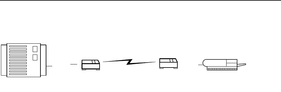
Example:
RS-232 RS-232
BlueRS+
DCE
Bluetooth
BlueRS+
DTE controlled client
DCE Mode
controlling device
DTE Mode
Setting of BlueRS+C2 DCE:
cmds=8
brad= boad of BlueRS+C2DTE
Setting of BlueRS+C2 DTE:
cmds=12
Don't forget to set the baudrate to the correct setting.

1.07work/09.2003 BlueRS+ manual
3. Using the BlueRS+C2
© Stollmann Entwicklungs- und Vertriebs-GmbH 9
3.2 AT command set for BlueRS+C2
All parameter can be changed by using an extended AT command set described in
this chapter.
Please check if the factory setting will fit with your environment. The factory setting is
described (highlighted) in the parameter list below.
If you want another configuration as set in the factory default setting, please do the
following steps:
• Connect the PC's com-port to the DTE interface of the BlueRS+C2.
• Connect the power supply to the mains socket.
• Start a terminal emulation on your PC, please verify that the baudrate setting of
the terminal emulation fits those of the BlueRS+C2.
• Set up the parameter of the BlueRS+C2 from the terminal emulation and save the
parameter using the AT command set.
Example:
To change the access mode to restricted please enter the following
commands:
AT**BRESTR=1<↵> (set restricted mode to ON)
AT&W<↵> (store the new configuration)
• Leave your terminal emulation and start your application program.
With the exception of the command A/ (Repeat command) all commands begin with
the prefix AT and are terminated with <↵>. Corrections in a command line are done
with <BACKSPACE>. A command line has a maximum of 80 characters. The
command line is automatically cancelled by longer input. Blanks are ignored,
capital/small letters are not significant.
The parameter settings of the BlueRS+C2 obtained when using the AT commands
can be permanently stored (AT&W) and are not lost by resetting or by leaving the AT
command mode.
To enter the AT command mode during an active data connection you must use the
following sequence ("Escape sequence"):
at least 1 sec pause <+><+><+> 1 sec pause
The time gap between all three plus signs may not exceed 1 sec.
The escape sequence is transmitted transparent to the remote device.

BlueRS+ manual 1.07work/09.2003
3. Using the BlueRS+C2
10 © Stollmann Entwicklungs- und Vertriebs-GmbH
By using initialization strings to configure the TA which includes more than one
parameter to be configured please follow the examples below:
• Initialization string includes standard AT commands:
AT&F&D2&C1E0&W
By using a special configuration command (at**<cmd>) in the initialization string you
have to set a semicolon <;> in case that additional commands will follow.
• Initialization string includes special AT commands:
AT&F**BR=8;&D2&C1E0&W
Supported commands:
A/ Repeat last command line
This command repeats the commands of the last entered command line.
Note: No prefix AT is required.
A/
A Accept incoming call
Using this command you can accept an incoming call, if automatic call acceptance is
not set (Register S0 = 0). An incoming call is always displayed by the message
“RING“ or the code “2“, also if automatic call acceptance is selected.
Must be the last command in an AT command line.
CONF Enter BlueRS+C2Configurator
Enters directly into the BlueRS+C2Configurator, the configuration prompt "#" will be
displayed. Leave the BlueRS+C2Configurator with the command "quit" (or “exit” or
“go”).
ATCONF
&C DCD control
Selects the behavior of the DCD control line from the BlueRS+C2.
AT&C BlueRS+C2 control line DCD is always ON
AT&C1 DCD ON indicates Bluetooth connection is established (default)
AT&C2 DCD line follows DTR
AT&C4 DCD follows remote DCD
D Initiate Bluetooth link

1.07work/09.2003 BlueRS+ manual
3. Using the BlueRS+C2
© Stollmann Entwicklungs- und Vertriebs-GmbH 11
This command addresses a Bluetooth device directly through it's address or name.
If a connection to a Bluetooth device requiring the restricted mode the pin has to be
set up using command AT**BPIN.
The link request will time out, if the Bluetooth address is not valid (about 6 seconds).
ATD <brad>|dx
brad: called Bluetooth remote device address (12 digits)
dx: references called Bluetooth remote device service
number in bdlist (d1..d9).
This command must be the last command in an AT command line.
Any character input while the RS+ is dialing will cancel the dialing procedure.
Examples:
ATD 0080371443AB Connect to Bluetooth device 0080371443AB
ATD d1 Connect to 1st Bluetooth device in bdlist (server channel
number defined in brsch)
Note:
The remote Bluetooth device has to be determined before issuing this link
request. This can be done in the following ways:
- get it manually by reading from the sticker of the remote Bluetooth device.
- Inquire the address and service by using the commands AT**BDINQ and
AT**BDLIST.
Give the BlueRS+C2 about 10 seconds after Reset to initialize before issuing
the first command.
&D DTR control
Selects the behavior of the BlueRS+C2, when the DTE control line DTR changes
from ON to OFF.
AT&D DTE control line DTR setting is ignored
AT&D2 DTE control line DTR is evaluated: dropping the DTR line by the
DTE will disconnect an existing Bluetooth link.
An incoming call will be accepted only with DTR active.
AT&D4 DTE control line DTR is partly evaluated:
- dropping the DTR line by the DTE will disconnect an existing
Bluetooth link (default).
- An incoming call will be accepted independent of DTR status.
E Local echo

BlueRS+ manual 1.07work/09.2003
3. Using the BlueRS+C2
12 © Stollmann Entwicklungs- und Vertriebs-GmbH
Selects the local echo in command mode.
ATE No local echo
ATE1 Local echo on in command phase (default)
&F Load factory defaults
Factory default will be loaded. (for storing in non volatile memory please use the
command AT&W).
AT&F setup all parameter concerning data port.
AT&F1 setup all parameter including Bluetooth specifics and passwords.
H Disconnect
Disconnects existing Bluetooth connection, after issuing the escape sequence (see
page 9).
ATH
I Display version information
Displays different information about version number and settings:
ATI Returns the "Modem"-type; name of the terminal adapter
(“BlueRS+C2“)
ATI1 Returns "0"
ATI2 Returns "OK"
ATI3 Returns version string: "V1.xyz"
ATI4 Returns manufacturers name: "Stollmann E+V GmbH"
ATI5 Returns "OK"
ATI6 Returns copyright string: "(c) Copyright Stollmann GmbH"
ATI7 Returns "OK"
ATI8 Returns "ERROR"
ATI9 Returns "OK" (Plug&Play ID-Request not supported)
ATI77 Returns Bootloader version string
ATI99 Returns software creation date
&K Flow control
Selects the flow control behavior of the BlueRS+C2 while in data communication
phase.
AT&K No local flow control between the DTE and BlueRS+C2 is used
AT&K3 Local flow control is set to hardware handshake RTS/CTS
(default)

1.07work/09.2003 BlueRS+ manual
3. Using the BlueRS+C2
© Stollmann Entwicklungs- und Vertriebs-GmbH 13
AT&K5 Local flow control is set to hardware handshake RTS/CTS
additionally in AT command phase
O Return to online state
If the BlueRS+C2 is in command mode after issuing an escape sequence out of an
existing connection, ATO brings the BlueRS+C2 back to data phase.
Must be the last command in AT command line.
ATO
Q Suppress results
With this command result codes or messages can be suppressed.
ATQ Returns status - codes after command input (default)
ATQ1 No result codes are returned
&R CTS control
Selects the behavior of the CTS control line from the BlueRS+C2.
AT&R BlueRS+C2 control line CTS is following all changes of RTS
AT&R1 CTS is always ON (default)
AT&R2 BlueRS+C2 control line CTS is following all changes of DTR
AT&R3 BlueRS+C2 control line CTS is following all changes of remote
CTS (set for cable replacement)
S Display and set internal S register
ATSnn? Show actual values (decimal) of selected register nn
ATSnn=xxx Set selected register nn to the decimal value xxx.
See S register definitions on page 21.
&S DSR control
Selects the behavior of the DSR control line from the BlueRS+C2.
AT&S BlueRS+C2 control line DSR is always ON (default)
AT&S1 DSR ON indicates Bluetooth link is established
AT&S2 BlueRS+C2 control line DSR is following all changes of DTR
AT&S3 BlueRS+C2 control line DSR is following all changes of DCD
AT&S4 BlueRS+C2 control line DSR is following all changes of remote
DSR (set for cable replacement)
AT&S5 reserved

BlueRS+ manual 1.07work/09.2003
3. Using the BlueRS+C2
14 © Stollmann Entwicklungs- und Vertriebs-GmbH
V Result format
ATV Result is presented as numbers (followed by <↵>)
ATV1 Result is presented as text (default)
&V Display configuration
AT&V Displays the actual configuration of AT command setting
AT&V1 Displays the actual configuration of extended AT command
setting
W Extended result codes
ATW Result is presented without extended result codes.
ATW1 Result is presented with extended result codes, Result
messages include error causes.
&W Store active configuration
The active configuration will be stored in non volatile memory.
AT&W
Z Load stored settings
The active configuration will be reset to the stored configuration.
Must be the last command in an AT command line.
ATZ
**DBITS Number of data bits x asynchronous chars (7,8)
Number of data bits x for asynchronous character (7,default: 8).
AT**DBITS=x
Note: only valid for br <> 0.
**PRTY Set parity of asynchronous characters
Selects the parity for asynchronous characters.

1.07work/09.2003 BlueRS+ manual
3. Using the BlueRS+C2
© Stollmann Entwicklungs- und Vertriebs-GmbH 15
0: no parity; 1: even parity; 2: odd parity
AT**PRTY=0 No parity (default)
AT**PRTY=1 Odd parity
AT**PRTY=2 Even parity
AT**PRTY=3 Space parity
AT**PRTY=4 Mark parity
Notes: To use other data formats than 10 bit (= (N1, 7E1, 7O1) you have to set br to
fixed speed.
- only valid for br <> 0.

BlueRS+ manual 1.07work/09.2003
3. Using the BlueRS+C2
16 © Stollmann Entwicklungs- und Vertriebs-GmbH
3.2.1 Bluetooth specific AT commands
Setting up special Bluetooth parameter:
**BACCTAB Show pairing information
To show the pairing information (setup due to a successful restricted
connection) within the BlueRS+C2 you have to issue the command
"AT**BACCTAB" .
Example: at**bacctab
Response: 1: used: YES BD: 00803714ECA4 name:
OK
**BDEL Delete pairing information
To delete the pairing information (setup due to a successful restricted
connection) within the BlueRS+C2 you have to issue the command
"AT**BDEL 1" . The paired Bluetooth device can be read out by the command
"AT**BACCTAB".
Example: at**bdel 1
Response: OK
**BDINQ Inquire Bluetooth devices
With this request the automatic scan of all discoverable Bluetooth devices will
be initiated.
As a result the creation of the list bdlist will be initiated. The list can be read
out using the command at**bdlist. If the Inquiry-scan has not been terminated
while issuing the command at**bdlist, the BlueRS+C2 will return "inquiry
active".
The entries contain the Bluetooth device address, the Bluetooth device names
and available services (profiles).
The creation of this list may take up to 20 seconds due to the reaction time of
the accessible Bluetooth devices, a maximum of 9 Bluetooth devices can be
listed.
When issuing the command "at**bdinq 1" the inquiry scan will only request the
Bluetooth addresses, name and service inquiry will not be performed. The
maximum waiting time for responses of the Bluetooth devices is limited by a
time defined with the command "at**binqtim".
Example: at**bdinq request Bluetooth devices with name and service.
Response: OK
at**bdinq 1 request Bluetooth device addresses only

1.07work/09.2003 BlueRS+ manual
3. Using the BlueRS+C2
© Stollmann Entwicklungs- und Vertriebs-GmbH 17
Response: OK
**BDLIST Show inquired Bluetooth devices
With this request the list of found Bluetooth devices will be returned, the
entries show the Bluetooth device address and the Bluetooth device name
requested by the command at**bdinq. For every Bluetooth device in addition
the available services (profiles) will be shown.
These entries can be accessed by the selectors d1 .. dn to address the
Bluetooth device and the selectors s1 .. sn to address the Bluetooth devices
service channel.
Example: at**bdlist
Responses: d1: <bradr1>, <bname1>
s1: <service1>, <server channel>, <bsname1>
s2: <service2>, <server channel>, <bsname2>
d2: <badr2>, <bname2>
s1: <service1>, <server channel>, <bsname3>
OK
or
inquire active ; if the search initiated by at**bdinq
OK ; is still active
or
list empty ; no Bluetooth device found
OK
brad found Bluetooth remote device address (12 digits)
bname found Bluetooth remote device name
service coding of service type
server channel used channel number for service type
**BINQTIM Timeout for Inquiry Scan
With this command the Inquiry Scan time will be limited to the configured
value (default: 8 = 10 seconds). See also command at**bdinq.
Allowed values: 1 to 48 (1,25 sec to 60 sec).
Example: at**binqtim=n set maximum wait time to n * 1.25 seconds
at**binqtim=2 set maximum wait time to 2.5 seconds
**BNAME BlueRS+C2 own device name
Defines the device name. bname is shown on a remote Bluetooth terminal

BlueRS+ manual 1.07work/09.2003
3. Using the BlueRS+C2
18 © Stollmann Entwicklungs- und Vertriebs-GmbH
device during a Service Discovery sequence It is a string constant according
to V.250.
Example: at**bname show own device name
at**bname=<rs+name> set own device name to rs+name
**BRAD Bluetooth Device Remote Address
With this command you can setup the Bluetooth address of the other Bluetooth
device, that should be connected using an automatic link setup.
Example:
AT**BRAD=0080371443AB
**BRNAME Displays connected device name
Displays the device name of the connected Bluetooth device.
This value is can not be changed.
Example: at**brname show connected device name
**BRSCH Set remote Bluetooth server channel
Set up server channel of the remote Bluetooth module, to that the Bluetooth
link shall be established.
The own server channel number is fixed to 1, only used for accepting
Bluetooth links.
Remote management between BlueRS+C2 is achieved using the server
channel 30.
default: 1
Example: at**brsch=1
**BSNAME BlueRS+C2 service name
Defines the service name of the BlueRS+C2. bsname is shown on a remote
Bluetooth terminal device during a Service Discovery sequence.
Example: at**bsname
at**bsname=<rs+srvname> set own device name to rs+srvname

1.07work/09.2003 BlueRS+ manual
3. Using the BlueRS+C2
© Stollmann Entwicklungs- und Vertriebs-GmbH 19
default: "BlueRS+C2 serial port"
Note:
To activate a new name for discoveries you have to make a power off/on
cycle.
**BRESTR Set restricted mode
Control the restricted mode for exchanging the Pin (Passkey). When set to 1
the setting of parameter bpin will be used to verify a pin with the requesting
Bluetooth device.
The pins of two bluetooth devices have to set to the same value, if one of
these devices allows only restricted connections. If a restricted connection has
been established one time between two Bluetooth devices these devices
know each other and are called as "paired" (see command "AT**BACCTAB"
for information about the paired Bluetooth device).
After a pairing has taken place Bluetooth links can be established between
these paired devices independent of the setting of the restricted mode!
To delete the pairing information within the BlueRS+C2 you have to issue the
command "AT**BDEL 1" .
**BPIN Bluetooth device Pin (Passkey)
Set the Pin for establishing a connection in the restricted mode by the
command "AT**BPIN=<old_pin>,<newpin>".
This Pin is always checked if
- the BlueRS+C2 is set to restricted mode
- the BlueRS+C2 is not set to restricted mode and the other Bluetooth
device is set to restricted mode.
The Pin has a fixed length of 4 digits, factory default: 0000.
To reset the Pin to factory default please use the command AT&F1 (all
parameter will be set to factory default.
Example: at**bpin=0000,1234 set Pin to 1234 (old Pin was 0000)
Note: After a pairing has taken place (Pin sucessful exchanged) Bluetooth
links can be established between these paired devices independent of the
setting of the restricted mode and the Pin!
**BOAD Bluetooth Device Own Address
With this command you can read out the own Bluetooth device address.
This value is can not be changed.

BlueRS+ manual 1.07work/09.2003
3. Using the BlueRS+C2
20 © Stollmann Entwicklungs- und Vertriebs-GmbH
Example:
AT**BOAD
**<cmd> Execute configuration command
Executes one configuration command, for definition of commands see page 27.
AT**<cmd>
More than one configuration command have to be separated by a ";".
AT**cmd1;**cmd2

1.07work/09.2003 BlueRS+ manual
3. Using the BlueRS+C2
© Stollmann Entwicklungs- und Vertriebs-GmbH 21
3.2.2 AT command S register set
S0 0: No automatic call acceptance, acceptance of an incoming call is
controlled by the data terminal (command ATA after RING)
1: Immediate call acceptance by the terminal adapter (default)
2..n: Call acceptance through the terminal adapter after n "RING"
messages.
S2 Escape Character (default = 43h)
S3 Carriage Return Character (default = 13)
S4 Line Feed Character (default = 10)
S5 Backspace Character (default = 08)
S7 Wait time for Carrier (sec) (default = 30 sec)
S9 Enable PNP functionality for Windows95 (default=1, enabled)
S91 0: default
1: all unknown AT commands will be answered with OK.
2: Windows 2000 compatibility: some AT commands will be answered
with OK, unknown AT commands will be answered with OK.
3.2.3 AT result codes
Result codes (numerical and verbose):
Code Text Meaning
0 OK Command completed
1 CONNECT <radr> Connection established
2 RING <radr > Indicates an incoming call (Link request
received)
3 NO CARRIER <berr> No synchronization (berr = BT error cause)
4 ERROR Illegal command or error that can not be
indicated otherwise
6 NO DIALTONE <berr > No access to Bluetooth? network (berr = BT
error)
7 BUSY < berr > Number engaged (berr = BT error cause)
8 NO ANSWER < berr > No connection; addressed Bluetooth device can
not be reached (berr = BT error cause)
Error cause display:
< berr > = BT release (error) cause, hexadecimal
Example: NO CARRIER <0104>
In AT command mode, error cause display (does not belong to the AT command
standard) can be turned on by issuing the command ATW1 (default). The shown
error causes use the coding defined by the Bluetooth definition (see page 36).

BlueRS+ manual 1.07work/09.2003
3. Using the BlueRS+C2
22 © Stollmann Entwicklungs- und Vertriebs-GmbH
3.3 Cable replacement
A pair of BlueRS+C2 devices can be used to operate as a RS232 cable
replacement. Typically one BlueRS+C2 has to operate as a DCE interface
("BlueRS+C2DCE", DSU9 female) and the other one as a DTE interface
("BlueRS+C2DTE", DSUB9 male). These devices have to be ordered with the
correct interfaces.
When ordering a pair of BlueRS+C2 both devices will have the correct setting to
operate without changing any parameter. The default behavior is as follows:
- The Bluetooth link is established directly and automatically after powering
on from the BlueRS+C2 operating in DCE mode
- the restricted mode is disabled
- data transfer is transparent set to baudrate 115200 bit/s
- all status lines are transparently transferred to the other device (local
flowcontrol is disabled).
- LED2 shows the Bluetooth connection status (ON = link established)
In detail the following settings differ from the factory default setting:
BlueRS+C2DCE:
cmds 8 Automatic connection establishment independent of any status
line.
cdtr 0 DTR line is not controlling the Bluetooth link
cdsr 4 DSR Output line of BlueRS+C2DCE follows DSR input line of
BlueRS+C2DTE
ccts 3 CTS Output line of BlueRS+C2DCE follows CTS input line of
BlueRS+C2DTE
cdcd 4 DCD Output line of BlueRS+C2DCE follows DCD input line of
BlueRS+C2DTE
cri 1 RI Output line of BlueRS+C2DCE follows RI input line of
BlueRS+C2DTE
flc 0 no hardware flowcontrol
BlueRS+C2DTE:
cmds 12 Only acceptance of incoming Bluetooth link requests.
cdtr 0 DSR line is not controlling the Bluetooth link (DTR is mapped
internally to DSR)
cdsr 4 DTR Output line of BlueRS+C2DTE follows DTR input line of
BlueRS+C2DCE (DTR is mapped internally to DSR)
ccts 3 RTS Output line of BlueRS+C2DTE follows RTS input line of
BlueRS+C2DCE (RTS is mapped internally to CTS)
flc 0 no hardware flowcontrol
1.07work/09.2003 BlueRS+ manual
3. Using the BlueRS+C2
© Stollmann Entwicklungs- und Vertriebs-GmbH 23
Note: to readout the mode of operation of the BlueRS+C2 please use the command
"devmode".
Don't forget to set the baudrate to the correct setting.
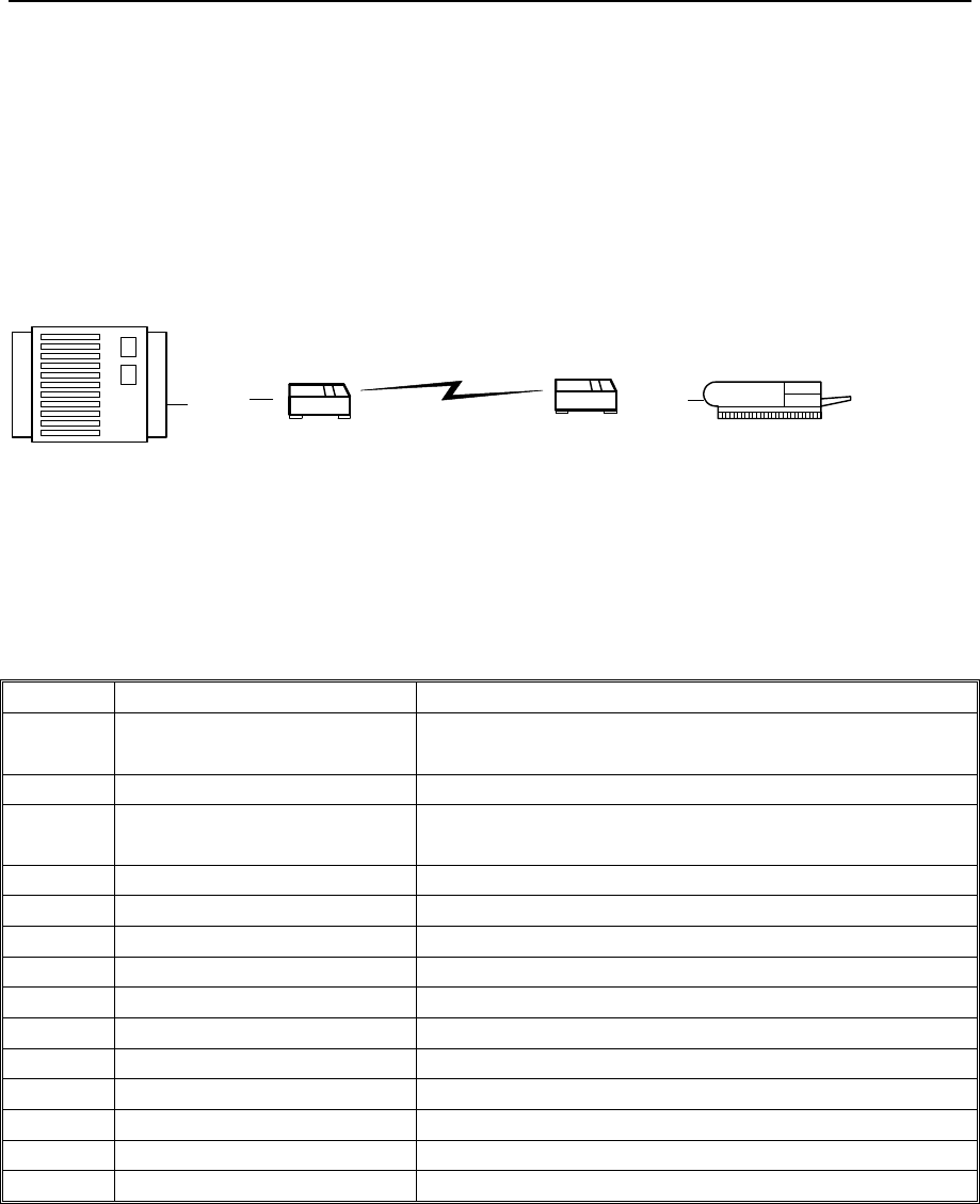
Example:
RS-232 RS-232
BlueRS+
DCE
Bluetooth
BlueRS+
DTE controlled client
DCE Mode
controlling device
DTE Mode
3.4 Table of coding of Bluetooth services
List of Bluetooth services (profiles):
Code Text Meaning
1101 SerialPort Serial port, serial data link without any
restriction
1102 LANAccessUsingPPP Lan Access with PPP protocol
1103 DialupNetworking Dial Up Networking to establish switched
connections to the ISDN or PSTN
1104 IrMCSync
1105 OBEXObjectPush OBEX Object Push
1106 OBEXFileTransfer OBEX Filetransfer
1107 IrMCSyncCommand
1108 Headset Headset access via Bluetooth
1109 Cordless Telephony
1100 Intercom
1111 Fax Fax
1112 HeadsetAudioGateway Headset Gateway for audio signals
1113 WAP
1114 WAP_CLIENT

BlueRS+ manual 1.07work/09.2003
4. BlueRS+C2 Configurator command set
24 © Stollmann Entwicklungs- und Vertriebs-GmbH
4 BlueRS+C2 Configurator command set
The settings of the BlueRS+C2 for the serial interface and the Bluetooth interface are
called configuration. The BlueRS+C2 is delivered with a set of pre-set values. In the
following section it will be shown how, by using the configuration commands, you can
examine the configuration of the BlueRS+C2 and if necessary change it. The values
can be stored in non volatile memory; this means they'll remain unchanged even if
the power supply is disconnected.
You can configure the BlueRS+C2 in the following ways:
• by using BlueRS+C2Configurator commands entered by a locally connected PC.
• by using the AT command set entered by a locally connected PC.
• Seite: 24
by using BlueRS+C2Configurator commands entered via the Bluetooth link
(remote configuration).
The BlueRS+C2Configurator can be entered in the following ways:
• by entering a special escape sequence (default: "!!!") after initialization
independent whether a Bluetooth link is established or not.
• by using a special command from the asynchronous dialup command interface
(AT: “ATCONF”).
• Seite: 24
remote via a Bluetooth connection from another Bluetooth device.
• or escape sequence in power up phase if enabled (rsttim>10, rstmsg=1).
4.1 Configuring the BlueRS+C2 after power on
• Connect the PC's com-port to the DTE interface of the BlueRS+C2.
• Start a terminal emulation program (i.e. Hyper-Terminal) with the following
settings: 9600 Baud, 8 databits, No Parity (8N1)
• Connect the BlueRS+C2 to the mains by the mains plug adaptor
• Wait until LED 2 starts blinking (after about 5 sec, see config cmd “rsttim“) and
the message to enter the config-sequence is displayed:
"+++ Press <CR>,<CR>,<ESC>,<ESC> to enter BlueRS+C2Configurator
+++"
• Type in quickly within 2 seconds after the message appears: <RET> <RET>
<ESC> <ESC>, to call up the BlueRS+C2Configurator.
• The BlueRS+C2Configurator acknowledges by giving a welcome string and a “#“
as the prompt character. Now you can work with the BlueRS+C2Configurator by
using the configuration commands (see page 27).
• Setup the parameter for the BlueRS+C2 from your terminal program and store
them.
Example:

1.07work/09.2003 BlueRS+ manual
4. BlueRS+C2 Configurator command set
© Stollmann Entwicklungs- und Vertriebs-GmbH 25
To set the baudrate to 9600 baud please enter the following commands:
br=4<↵> (set baudrate to 9600 baud)
save<↵> (store the new configuration)
quit<↵> (leave the BlueRS+C2Configurator and activate the new
value settings)
Hint: The active set of parameters can be displayed on screen by the
BlueRS+C2Configurator with the command "show<↵>".
• Leave the terminal program and start your application.
Now you can use the BlueRS+C2 with the new set of parameters by running the
needed PC program.
4.2 Configuring the BlueRS+C2 with AT commands
To execute one BlueRS+C2Configuration command cmd out of the AT command
mode you have to issue the command: “at**cmd” .
To call up the BlueRS+C2Configurator please use the command “atconf”.
You can leave the BlueRS+C2Configurator by the command “quit” (or „exit“ or „go“).
4.3 Remote Configuration using the TA+Configurator commands
The BlueRS+C2 to be configured is referred here as “remote BlueRS+C2”.
The BlueRS+C2 to configure is referred as “local BlueRS+C2”.
Please make sure that the remote BlueRS+C2 to be configured at the other end is
powered up.
• Connect the PC's com-port to the DTE interface of the local BlueRS+C2.
• Connect the power supply to the mains socket.
• Start a terminal emulation program (i.e. Windows-Terminal)
• Configure the local BlueRS+C2 with the special service channel 30
(brsch=30).
• Set up a Bluetooth-Link to the remote BlueRS+C2 to be configured by using
the command: ATD<brad><↵>.
The called BlueRS+C2Configurator acknowledges by requesting the remote
password. Please enter the correct password (default: no password, just
return). Now you can work with the BlueRS+C2Configurator by using the
BlueRS+C2Configurator commands (see page 24).
• Configure the parameter for the remote BlueRS+C2 from your terminal
program and store them (if wanted). (see page 27).
Hint: The active set of parameters can be displayed on screen by the

BlueRS+ manual 1.07work/09.2003
4. BlueRS+C2 Configurator command set
26 © Stollmann Entwicklungs- und Vertriebs-GmbH
BlueRS+C2Configurator with the command "show<↵>".
If necessary the remote BlueRS+C2 can be reset using the command
"reset<↵>".
• Hang up the Bluetooth connection by leaving the BlueRS+C2Configurator
using the command quit.
Leave your terminal program. After the next reset the changes will be active.
• Restore the server channel to the desired value, default to 1 (brsch=1).
Now the configured remote BlueRS+C2 with the new set of parameters can be used
by running the needed PC program.

1.07work/09.2003 BlueRS+ manual
4. BlueRS+C2 Configurator command set
© Stollmann Entwicklungs- und Vertriebs-GmbH 27
4.4 List of BlueRS+C2Configurator commands
The BlueRS+C2Configurator commands typed in must have the correct syntax and
be complete, including all blanks. Capital/small letter use is not important. The entry
is not case sensitive.
The bolded values are factory defaults. The usage is:
[?]<command>[=parameter]
Example to set the baudrate to 9600 baud:
br=4
Example to show the selected baudrate:
br
Example to show all selectable baudrates:
?br
To get an overview about the commands of your BlueRS+C2 some major commands
here as a preview:
show show the usually used parameter
showall show all changeable parameter
quit leave BlueRS+C2Configurator
help show all available commands
defa 1 setup factory default parameter set
save store parameter non volatile
at.sx AT command parameter set
AT command set only:
Handle AT specific settings.
Show and change AT S registers by entering the new value.
at.s0 show setting of S0-Register
at.s0=1 set Register S0 to 1
boad Bluetooth Device Own Address
With this command you can read out the own Bluetooth device address.
(read only)
Example:
boad
bpin Bluetooth device Pin (Passkey)

BlueRS+ manual 1.07work/09.2003
4. BlueRS+C2 Configurator command set
28 © Stollmann Entwicklungs- und Vertriebs-GmbH
Set the Pin for setting up a connection in restricted mode.
br baudrate asynchronous
Selection of the asynchronous baudrate for the DTE interface
1: 1200 bit/s
2: 2400 bit/s
3: 4800 bit/s
4: 9600 bit/s
5: 19200 bit/s
6: 38400 bit/s
7: 57600 bit/s
8: 115200 bit/s (default)
9: 230400 bit/s
20: 300 bit/s
21: 600 bit/s
brad Bluetooth Device Remote Address
With this command you can setup the Bluetooth address of the other Bluetooth
device, that should be connected using an automatic link setup.
Example:
brad=0080371443AB
brestr Set restricted mode
Enable and disable the restricted mode with exchanging the Pin (Passkey).
cato call timeout to abort
Time to abort a call if not successful connected after n seconds.
n = {3..255}, default: 15 seconds.
capa call pause
Automatic call: set a call pause for n seconds before next call attempt.
n = 0 : no call retry, default: 3 seconds.

1.07work/09.2003 BlueRS+ manual
4. BlueRS+C2 Configurator command set
© Stollmann Entwicklungs- und Vertriebs-GmbH 29
ccts CTS control
CTS control
0 : CTS follows RTS
1 : CTS always ON (default)
2 : CTS follows DTR
3 : CTS follows remote CTS line status
cdcd DCD control
DCD control
0 : DCD always ON
1 : DCD indicates a Bluetooth connection (default)
2 : follows DTR
4 : follows remote DCD
cdsr DSR control
DSR control
0 : DSR always ON (default)
1 : DSR indicates a Bluetooth connection
2 : DSR follows DTR line status
3 : DSR follows DCD line status
4 : DSR follows remote DSR line status
cdtr DTR control
Usage of DTR to control a Bluetooth connection
0 : No control:
Incoming calls will be accepted independent of DTR status;
DTR drop does not disconnect an active connection.
2 : DTR off disconnects
Incoming calls will be accepted only when DTR is ON;
DTR drop disconnects an active connection.
4 : DTR ignore and DTR drop disconnects (default)
Incoming calls will be accepted independent of DTR status;
DTR drop disconnects an active connection.

BlueRS+ manual 1.07work/09.2003
4. BlueRS+C2 Configurator command set
30 © Stollmann Entwicklungs- und Vertriebs-GmbH
cmds command set (note 1)
Command set for connection control
0: AT command set (default)
6: Automatic connection establishment when DTR is ON.
7: Automatic connection establishment when transmit data are available.
8: Automatic connection establishment independent of any status line.
12: No connection establishment initiated by this module.
Note: For details see the appropriate chapters.
cpua, cpua2, cpl3 Output pin behavior (BlueRS+C2 module only)
(under development)
Definition of the behavior of the output pins UA UA2 and L3 of BlueRS+C2.
The behavior can be configured by using one of the following setting to the value of
the list below.
The output level can be inverted by adding 128 to the desired value (defines the
output pin to low active).
0: always OFF. Default UA, UA2, L3
1: always ON
29: Bluetooth link established, same as DCD on V.24.
cri RI control
RI control
0 : RI is set with an incoming Bluetooth link request (default)
1 : RI follows remote RI line status
defa default settings
Sets up factory default parameter setting.
defa 0: setup all parameter concerning data port
defa 1: setup all parameter to factory defaults including Bluetooth
parameter.
devmode device mode strapping
Shows the mode of operation of the BlueRS+C2: DTE or DCE mode.

1.07work/09.2003 BlueRS+ manual
4. BlueRS+C2 Configurator command set
© Stollmann Entwicklungs- und Vertriebs-GmbH 31
When selecting DTE mode two additional inputs are evaluated and mapped to
the behavior of DCD (Pin 18) and RI (Pin 11).
0 : DTE mode
1 : DCE mode
Note: If you are working in DCE mode using the plug-on module, please make sure,
that PIN20 of connector P1 is connected to GND.
dbits asynchronous databits
Number of data bits asynchronous chars (default: 8) 7,8
Note: To use other data formats than 10 bit (8N1, 7E1, 7O1) you have to set br to
fixed speed.
flc flowcontrol
Flowcontrol to DTE
0 : No flowcontrol
3 : Hardware flowcontrol RTS/CTS (default)
5 : Hardware flowcontrol RTS/CTS additionally in AT command phase
flash load new firmware
This commands loads new firmware into the BlueRS+C2. The actual firmware
will be overwritten.
The firmware will be stored into the used part of the flash memory. While
uploading the following checks will be performed:
- File transfer protocol is XMODEM1K
- An overall firmware checksum is used.
- The firmware type written in the module header of the firmware must be
compatible to the hardware- and allowed firmware type (stored inside the
Bootloader).
This command is available only via the local serial port.
idle Idle data timeout
Timer to disconnect the Bluetooth link after inactivity on the serial line (sec).
0: inactive (default)
1..n: delay time to disconnect in seconds (1..255).

BlueRS+ manual 1.07work/09.2003
4. BlueRS+C2 Configurator command set
32 © Stollmann Entwicklungs- und Vertriebs-GmbH
load Load stored parameter setting
All parameters stored in non volatile ram will be loaded.
opt option register for AT register
option register representing the setting of some AT commands:
bit 0: 1 = echo on, equals ATE1
bit 1: 1 = quiet, equals ATQ1
bit 2: 1 = numeric response, equals ATV0
prty asynchronous parity
Parity of asynchronous character (default: no parity)
0 : No parity; 1 : Odd parity; 2 : Even parity, 3 : space parity, 4 : mark parity
Note: To use other data formats than 10 bit (8N1, 7E1, 7O1) you have to set br to
fixed speed.
quit, exit, go activate parameter changes
Activates the actual parameter settings and leave the BlueRS+C2Configurator
(without storing the parameter in non volatile memory ).
reset reset BlueRS+C2
Resets the whole functionality of the BlueRS+C2 by a forced hardware reset
(like Power off / on).
Refer also to parameter rsttim.
rsttim startup timer
Startup delay timer after reset. Within this period the configuration can be
entered after reset.
1 .. 255 : reset phase in 100 milliseconds, default: 40 (4 seconds)

1.07work/09.2003 BlueRS+ manual
4. BlueRS+C2 Configurator command set
© Stollmann Entwicklungs- und Vertriebs-GmbH 33
save store parameter changes
Stores the actual set of parameters in non volatile memory
sbits number of stopbits
Number of stopbits of asynchronous character
1 : One stopbit (default); 2 : two stopbit
Note: To use other data formats than 10 bit (8N1, 7E1, 7O1) you have to set br to
fixed speed.
show show parameters
Displays the actual set of parameters
showall show all parameters
Displays the all accessible parameters
trcnnn commands for internal trace
The usage of the commands for internal trace are described in chapter 5.3.
ver show version string
Displays detailed information about the software version and BlueRS+C2
type.
verb show version string of Bootloader
Displays detailed information about the software version of the Bootloader.
<cmd>? more information for one command
Displays the allowed values for one selected command <cmd>
?? help

BlueRS+ manual 1.07work/09.2003
4. BlueRS+C2 Configurator command set
34 © Stollmann Entwicklungs- und Vertriebs-GmbH
Displays help texts for all commands
Notes:

1.07work/09.2003 BlueRS+ manual
4. BlueRS+C2 Configurator command set
© Stollmann Entwicklungs- und Vertriebs-GmbH 35
4.5 Software update
The BlueRS+C2 uses a Flash-EPROM for software updates to store the operational
software. This software can be updated from a local connected PC via the COM port
or via an remote configuration connection. Please fulfill the following steps to update
the BlueRS+C2:
• Get a new software release for the BlueRS+C2 from your supplier or
http://www.stollmann.de/ or ftp://ftp.stollmann.de/ and copy it to your PC.
• Start a terminal emulation on your PC with the capability to run an X-MODEM-1K
file transfer (i.e. HyperTerminal).
• Local update: enter the BlueRS+C2Configurator.
• Enter the BlueRS+C2Configuration command "flash".
• Wait for end of erasing the Flash-EPROM and the prompt to start your X-
MODEM transfer.
• Start the 1k-X-MODEM file transfer (send file or upload) by selecting the Transfer
/ Send File menu point in your terminal emulation and select the new software.
• After completion you will get the information whether the software update ended
successfully or erroneous.
• The loaded new firmware will be activated automatically.
• Due to new functionality the last stored configuration setting may be lost, please
check before using.
For more details refer to the description of the commands flash in the chapter ”List of
BlueRS+C2Configurator commands” on page 27.
Note:
Due to an error it may be that no firmware is active within the BlueRS+C2.
This will be indicated by continuous flashing of the LEDs L1, L2 (Bootloader
active). To store a new firmware correctly you have to enter the command
at**flash and load a firmware using the XMODEM protocol as described
above. This Bootloader supports only AT**cmd with fixed baudrate of 115.200
Baud.

BlueRS+ manual 1.07work/09.2003
5. Diagnostic and error messages
36 © Stollmann Entwicklungs- und Vertriebs-GmbH
5 Diagnostic and error messages
For the diagnostic of erroneous situations the following functionality is supported.
Please check first the behavior of LED displays, if an Bluetooth link can not be
established. Refer to list of LED displays on page 42.
5.1 Error messages from AT command set
When the extended result messages are selected using the command ATW1
Bluetooth error codes are displayed in addition to the standard AT result messages.
Bluetooth error codes are always coded as <xxxx>. The meaning can be taken from
the following tables Bluetooth error codes (see page 36).
5.2 Bluetooth error codes
Note: error codes marked with (i) are internal errors.
Error cause
hexadecimal
Meaning Translation
to AT result
codes
0x0000 no error, no explanation 3
0x0001 driver and application version mismatch 3
0x0002 application id provided is not correct 3
0x0003 unknown message code in message 3
0x0004 not enough resources to complete request (out of
descriptor etc)
3
0x0005 at least one parameter of the message is wrong 3
0x0006 no adapter plugged in 3
0x0007 too much outstanding messages in downstream
direction
6
0x0008 driver is busy, repeat request later 6
0x0009 error in message transport system (driver not correct
installed?)
3
0x0101 (i) HCI_ERR_UNKNOWN_COMMAND 3
0x0102 (i) HCI_ERR_NOCONNECTION 3
0x0103 bluetooth adapter crashed 3
0x0104/260 remote bluetooth device not found (wrong address?,
out of range?)
8
0x0105 authentication error(wrong pin code supplied?) 3
0x0106 (i) HCI_ERR_KEY_MISSING 3
0x0107 (i) HCI_ERR_MEMORY_FULL 3
0x0108/264 lost connection to remote bluetooth device
(
out of 3

1.07work/09.2003 BlueRS+ manual
5. Diagnostic and error messages
© Stollmann Entwicklungs- und Vertriebs-GmbH 37
range)
0x0109 max no of connections exceeded 6
0x010a max no of voice connections exceeded 6
0x010b (i) HCI_ERR_ACL_CONN_ALREADY_EXISTS 3
0x010c (i) HCI_ERR_COMMAND_DISALLOWED 3
0x010d connection attempt by remote side rejected 3
0x010e connection attempt by remote side rejected 3
0x010f connection attempt by remote side rejected 3
0x0110 connection attempt by remote side timed out 8
0x0111 (i) HCI_ERR_UNSUPPORTED_PARAM_VALUE 3
0x0112 (i) HCI_ERR_INVALID_HCI_PARAMETER_VALUE 3
0x0113 connection terminated by remote side 3
0x0114 connection terminated by remote side 3
0x0115 connection terminated by remote side 3
0x0116 connection terminated by local side 3
0x0117 (i) HCI_ERR_REPEATED_ATTEMPTS 3
0x0118 authentication rejected by remote side 3
0x0119 incompatible remote bluetooth adapter 3
0x011a unspecified error 3
0x011b (i) HCI_ERR_UNSUPPORTED_LMP_PARAMETER_VAL 3
0x011c master slave role switch not allowed 3
0x011d connect lost to remote Bluetooth adapter (link
manager)
3
0x011e (i) (HCI_ERR_LMP_ERROR_TRANSACTION_COLLISION 3
0x011f (i) HCI_ERR_LMP_PDU_NOT_ALLOWED 3
0x0120 attempt to enable encryption failed 3
0x0121 information: unit key used 3
0x0122 (i) quality of service not supported. 3
0x0123 (i) HCI_ERR_INSTANT_PASSED 3
0x0124 (i) unit key not supported 3
0x0164 (i) HCI_ERR_ILLEGAL_HANDLE 3
0x0165 initialization of adapter failed (timeout) 6
0x0166 initialization of adapter failed (synchronization) 6
0x0201 (i) connection went to state pending 3
0x0202 protocol not supported by remote side 3
0x0203 connection refused due to security conditions 3
0x0204 out of resources 3
0x02ee remote side timed out 3
0x0301 version of remote SDP entity not compatible 3
0x0302 invalid service record handle 3
0x0303 invalid request syntax 3
0x0304 invalid size of pdu 3
0x0305 continuation state is invalid 3

BlueRS+ manual 1.07work/09.2003
5. Diagnostic and error messages
38 © Stollmann Entwicklungs- und Vertriebs-GmbH
0x0306 not enough resources to complete operation 3
0x0364 client received unhandled SDP opcode 3
0x0365 No answer from server(timeout) 3
0x0366 specified service not found 3
0x0367 Syntax Error in Response from server 3
0x0464 Connection setup was rejected by remote side (DM),
i.e. the Pin exchange has failed in restricted mode
3
0x0465 Connection timed out (no response) 8
0x0466 Non Supported Command received (incompatible
remote side)
3
0x0467 Illegal parameter 3
Note: error codes marked with (i) are internal errors.

1.07work/09.2003 BlueRS+ manual
5. Diagnostic and error messages
© Stollmann Entwicklungs- und Vertriebs-GmbH 39
5.3 Diagnostic using the internal Trace
For more sophisticated debugging an internal trace functionality is implemented. This
logging mechanism allows to write activities of the Bluetooth interfaces and the serial
interface into a wrap around buffer. The type of entries can be selected by a trace
mask.
trcmsk set trace mask
trcmsk par Setup the mask to select the type of data to be written into the trace
buffer.
Default: Bluetooth HCI and Blueface messages, DTE interface lines,
DTE-Data in connection-setup and clearing-phase.
The parameter par has to be setup in the following way, all bytes have
to be entered (default 00 00 00 00 00 00 00 00 04):
par := bl1 bl2 bl3 dl1 dl2 dl3 sl1 app bt1
bl1 reserved (00)
bl2 reserved (00)
bl3 reserved (00)
dl1 reserved (00)
dl2 reserved (00)
dl3 reserved (00)
sl1 Serial line 1; i.e. first V.24 port; default: 00
bit0: control lines after change
bit2: data bytes while connection control (call phase)
app reserved (00)
bt1 Bluetooth; default: 04
bit0: hci interface, commands and events
bit1: hci interface, acl data
bit2: Blueface interface: signaling
bit3: Blueface interface: traffic while DCD off
bit4: Blueface interface: traffic
examples:
trcmsk 000000000000000004 Trace Bluetooth messages and V.24
commands.
trcon start trace write
trcon set trace to active regarding to trace mask

BlueRS+ manual 1.07work/09.2003
5. Diagnostic and error messages
40 © Stollmann Entwicklungs- und Vertriebs-GmbH
trcoff stop trace write
trcoff set trace to OFF independent of trace mask
trcclr clear trace buffer
trcclr clear actual trace buffer contents
trcread read trace buffer
trcread Output of the complete trace buffer in hexadecimal chars (ASCII, max.
line length 72 chars).
Every entry of the trace buffer is output using the following format:
Entry number – Timestamp – Type – Length – Databytes
Entry number Sequence number of entry
Timestamp in units of 10 ms
TypeAndSource Source of traceentry:
bit0-7: type from trace mask
bit8-14: source of trace entry:
bit15: 0xxx : incoming event (from Bluetooth link)
8xxx : outgoing event (to Bluetooth link)
“FFFF“ : Reset for firmware
Length Length of following data bytes
Databytes Data bytes; continued lines are indicated by an “>“.
Coding of trace data bytes dependent of TypeAndSource:
0901/8901: Serial line control line change:
bit0 : 1 = DSR is ON
bit1 : 1 = DCD is ON
bit2 : 1 = CTS is ON
bit3 : 1 = RING is ON
bit4 : 1 = RTS is ON
bit5 : 1 = DTR is ON

1.07work/09.2003 BlueRS+ manual
6. Appendix
© Stollmann Entwicklungs- und Vertriebs-GmbH 41
6 Appendix
A1: Technical data BlueRS+C2
BlueRS+C2 desktop model serial interface:
functional: V.24
electrical: V.28
mechanical: 9 pin DSUB connector (female)
BlueRS+C2 module serial interface:
functional: V.24
electrical: TTL
mechanical: double pin rows P1
Transmission speeds:
DTE: 1200 – 230400 bit/s (asynchronous)
Character representation: 8Bit no Parity, 1 stop bit
7Bit even/odd Parity, 1 stop bit
Character synchronization: asynchronous
Operating mode: half duplex or full duplex
Flowcontrol Hardware (RTS/CTS)
Bluetooth link: RF part: +4 dBm Radio,
20 m (Bluetooth Power Class 2)
Bluetooth Spec: 1.0 B (1.12.1999)
Flowcontrol credit based
Class 1 module: RF part: +20 dBm Radio,
100 m (Bluetooth Power Class 1)
Bluetooth antenna: internal or external via coax SMC connector
Physical dimensions:
BlueRS+C2-Dx: desktop casing: 71 x 22 x 123 mm (WxHxD)
BlueRS+C2-Mx: plug on module: 56 x 56 x 12s mm
(WxHxD)
Power supply:
BlueRS+C2-Dx: external power supply 5V DC.
idle: ca. 75 mA, active: ca. 115 mA.
BlueRS+C2-Mx5: 5V DC, +-5%, via double pin row P2
idle: ca. 30 mA, active: ca. 70 mA.

BlueRS+ manual 1.07work/09.2003
6. Appendix
42 © Stollmann Entwicklungs- und Vertriebs-GmbH
A2: LED displays BlueRS+C2 desktop models
Active states:
L1 L2 Status
Θ Θ (2sec) Power-On-Phase ; Bootloader, Init active, wait
⊗ O Ready, idle ; Initializing ok, no Bluetooth link established
∅ O Ready, power down; Init ok, no Bluetooth link established
⊗ ∅ Connecting ; Bluetooth link will be established
⊗ ⊗ Connected ; Bluetooth link established
Error states:
L1 L2 Status
O O BlueRS+C2 not ok ; Hardware error, BlueRS+C2 repair
necessary
O Θ (nx1s) BlueRS+C2 not ok ; Hardware error, BlueRS+C2 repair
necessary
Θ Θ L1, L2 flashing: Bootloader active, no operational firmware
programmed. Use command at**flash to
download firmware with 115200 Bd ,N81
(see page 35).
LED Legend:
⊗ On
∅ occ short on, long off Cycle 1 to 2 sec
⊕ fl long on, short off Cycle 1 sec
Θ (nxms) continuous blinking: n times every m seconds
O Off
1.07work/09.2003 BlueRS+ manual
6. Appendix
© Stollmann Entwicklungs- und Vertriebs-GmbH 43
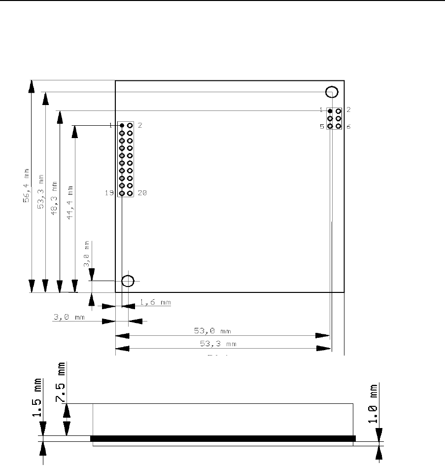
A3: Mechanical dimensions of the BlueRS+C2 module

BlueRS+ manual 1.07work/09.2003
6. Appendix
44 © Stollmann Entwicklungs- und Vertriebs-GmbH
A4: BlueRS+C2 Serial Interface Connector P1
P1-Pin Signal Direction
from
BlueRS+C2
BlueRS+C2 usage External
interfacing
1 GND I 0V-Power 0V Power
supply
2 VCC I +5V-Power +5V Power
supply
3 GND GND GND
4 TXD~ I
5 GND GND GND
6 RXD~ O
7 ID2 O GND NC or READ
8 RTS~ I
9 ID1 O GND NC or READ
10 CTS~ O
11 RESET I RESET active low (OC) NC
12 DTR~ I
13 L3~ (UA0) O (internal 10k Pull up) NC or status
info
14 DCD~ O
15 RI~ O
16 DSR~ O
17 UA~ O User Output 1 NC or status
info
18 UE~ I User Input 1 10k Pull up
19 UA2 O User Output 2 NC or status
info
20 UE2 I User Input 2 GND
Outputs:
UA: default: similar to L1 of BlueRS+C2-Dx
L3: Bluetooth link established
UA2: reserved
Inputs:
UE: reserved
UE2: select DCE/DTE mode. GND=DCE mode.
Inputs and output lines with '~' are low active (i.e. ON has the TTL level 0VDC)

1.07work/09.2003 BlueRS+ manual
6. Appendix
© Stollmann Entwicklungs- und Vertriebs-GmbH 45
A5: BlueRS+C2 Interface Connector P2
If mounted:
P2-Pin Signal Direction
1 NC -
2 NC -
3 NC -
4 NC -
5 NC -
6 NC -
A6: Pinout of the V.24/V.28 interface BlueRS+C2 desktop models (DSUB 9)
Pin
V.24/V.28
I/O
TEXT
ITU
DIN
EIA
1
109
M5
DCD
O
Data carrier detect
2
104
D2
R D
O
Receive data
3
103
D1
T D
I
Transmit data
4
108/1
108/2
S1.1
S1.2
DTR
I
Data terminal ready
5
102
E2
GND
---
Signal ground
6
107
M1
DSR
O
Data set ready
7
105
S2
RTS
I
Request to send
8
106
M2
CTS
O
Clear to send
9
125
M3
RI
O
Ring indicator