Telkonet SS6560 EcoTouch User Manual EcoInsight
Telkonet, Inc. EcoTouch EcoInsight
UserManual.wiki
>
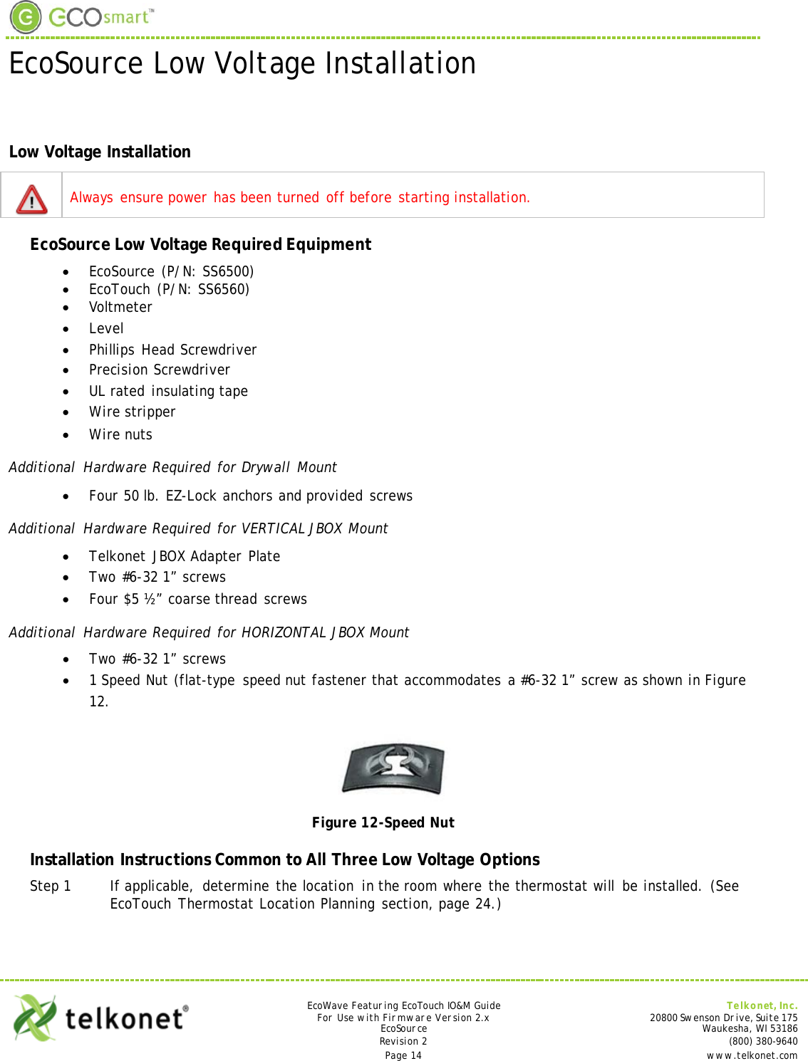
Telkonet
>
SS6560 User Manual
User Manual
Navigation menu
Upload a User Manual
Namespaces
Wiki Guide
HTML
PDF
Info
Views
User Manual
Discussion / Help
Navigation