User Manual
EcoWave Featuring the EcoTouch
Installation, Operation & Maintenance Guide

Table of Contents
Table of Contents ............................................................................................................... i
Introduction...................................................................................................................... 1
Conventions Used in this Guide............................................................................................. 1
The EcoSmart Energy Management System ............................................................................... 2
Regulatory Compliance ...................................................................................................... 2
Overview: EcoWave Remote Thermostat/Controller Package.......................................................... 3
EcoSource ........................................................................................................................ 5
Wiring .......................................................................................................................... 5
High/Low Voltage Options .................................................................................................. 6
High Voltage Installation .................................................................................................... 6
Low Voltage Installation ................................................................................................... 14
Instructions Common to All Three Low Voltage Options .............................................................. 21
EcoTouch ....................................................................................................................... 24
EcoTouch Location Planning .............................................................................................. 24
Installation .................................................................................................................. 26
EcoTouch Guest Screen Controls & User Interface..................................................................... 29
Device Association ............................................................................................................ 31
Pair EcoTouch with EcoSource............................................................................................ 31
EcoTouch Configuration Changes ........................................................................................... 32
Change Channel ............................................................................................................ 32
Unpair EcoTouch............................................................................................................ 32
Activate “Display Mode” Option .......................................................................................... 32
System Status Screen ...................................................................................................... 32
Regular Maintenance ......................................................................................................... 33
Troubleshooting ............................................................................................................... 34
Troubleshooting ............................................................................................................... 35
Troubleshooting ............................................................................................................... 36
Index ......................................................................................................................... 37
Appendix A .................................................................................................................. 39
EcoWave Featuring EcoTouch IO&M Guide Telkonet, Inc.
For Use with Firmware Version 2.x 20800 Swenson Drive, Suite 175
Table of Contents Waukesha, WI 53186
Revision 2 (800) 380-9640
Page i www.telkonet.com

Company Headquarters:
Customer Support:
EcoSmart Sales:
Telkonet, Inc.
(800) 380-9640
(888) 703-9398
20800 Swenson Drive
Email:
Email
Suite 175
ecosmartsupport@telkonet.com
sales@telkonet.com
Waukesha, WI 53186
P (414) 223-0473
F (414) 258-8307
EcoWave Featuring EcoTouch IO&M Guide Telkonet, Inc.
For Use with Firmware Version 2.x 20800 Swenson Drive, Suite 175
Table of Contents Waukesha, WI 53186
Revision 2 (800) 380-9640
Page ii www.telkonet.com
Introduction
Conventions Used in this Guide
This is an informational tip, used to convey
relevant but not necessarily urgent
information.
This is a warning, used to convey important
information.
This is a strong warning, used to convey
urgent and often safety-related information.
Chapter Names
Main chapters in this manual will have headings in large green
font as shown above. Main chapter names also appear in the
footer.
Sub-Chap ter Names
Within the main chapters will be relevant sub-chapters, which
are presented with bold, black headings as shown above.
Footers
Footers contain the document name, chapter name, document
version number and page number, as shown here:
Procedure: Steps Described Here
Procedural Steps are indicated as such in the heading, which
begins with the word, “Procedure:” as shown above. The steps
are outlined as shown in the following example:
Step 1 Navigate to the Config Menu > Alert Setup.
Step 2 Clic k t he Add New Alert Trigger button in
the top left corner of the Alert Setup Screen.
Step 3 Enter a descriptive A lert Name.
Introducing a New Screen
When a screen is introduced, a screen print is provided. Below
the screen print will be its location and an explanation of the
screen’s intended purpose as shown in this example:
Screen and Tab Names
Screen and Tab names are underlined, as shown in this example:
The Thermostat Status Screen shows all rooms and
their status information at a glance.
Field Names
Field names appear in bold font; field explanations appear next
to the field name as shown in this example:
Device Select the device type.
Position The order in which attached devices are
associated.
MAC Address MAC address of the attached device.
Field Selection Choices
Field selection choices are in italics as shown in this example:
Select the Alerting Device Type from the dropdown
menu. Choices are: All Thermostats, All Pipe Sensors,
Single Device and Outdoor Temperature.
The “>” Sy mbol
The ">" symbol is used to describe a menu choice and command
selection. For example:
Configuration Menu > Alert Setup means click on the
Configuration Menu, then click on Alert Setup.
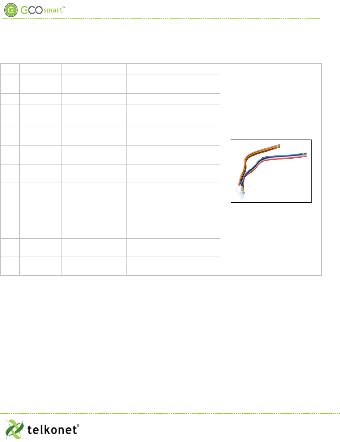
Tables
Tables provide visual presentations of related data such as
hardware components and explanations as shown in this
example:
Pin Label on Backplate Function
1 iaculis Lorem ipsum dolor sit
amet.
2 velit
Fusce pharetra risus eu
nibh consequat volutpat.
3 sagittis Uisque laoreet augue eu
elit dignissim feugiat.
Troubleshooting
Assistance with troubleshooting begins with the red header as
shown above.
EcoWave Featuring EcoTouch IO&M Guide Telkonet, Inc.
For Use with Firmware Version 2.x 20800 Swenson Drive, Suite 175
Introduction Waukesha, WI 53186
Revision 2 (800) 380-9640
Page 1 www.telkonet.com

EcoWave Package Overview
The EcoSmart Energy Management System
The EcoSmart Energy Management System reduces HVAC energy consumption without interfering with occupant
comfort.
EcoSmart thermostats such as the EcoTouch automatically learn and adapt to the heating and cooling patterns
of each room. For example, a room on the east side of a building will receive direct sunlight in the morning and
will either need less HVAC heating or more HVAC cooling. However, as the day progresses, the room will need
more HVAC heating or less HVAC cooling as it moves into the shade. An EcoSmart thermostat will continually
monitor the room, learn its patterns, and adjust its heating and cooling profiles accordingly.
EcoSmart thermostats also learn and adapt to occupant schedules. When a room is unoccupied, the EcoTouch
will enter an energy saving mode, allowing the room to drift away from the desired set point. During this drift
period, the thermostat will operate the HVAC unit less often, reducing energy costs. When the room becomes
occupied again, the RecoveryTime™ technology built into each EcoTouch will return the room to the set point
without occupant interaction.
The EcoWave is available in several configurations to address specific requirements of multiple applications
including hotel, classroom, office, university dormitory, military residence hall, retail, public area, convention
center, and a wide variety of commercial and industrial spaces.
The firmware of standalone EcoWave thermostats is identical to the firmware of networked versions.
Standalone Thermostats can be networked by adding a network module to the base units at any time.
Programming features used during installation, maintenance, and troubleshooting are available in the on-
screen Maintenance Menu.
Regulatory Compliance
FCC ID: XV6SS6560
This device complies with Part 15 of the FCC Rules. Operation is subject to the following two conditions: (1)
this device may not cause harmful interference, and (2) this device must accept any interference received,
including interference that may cause undesired operation.
This equipment has been tested and found to comply with the limits for a class B digital device pursuant to
part 15 of the FCC Rules. These limits are designed to provide reasonable protection against harmful
interference in a residential installation. This equipment generates, uses and can radiate radio frequency
energy and if not installed and used in accordance with the instructions, may cause harmful interference to
radio communications. However, there is no guarantee that interference will not occur in a particular
installation. If the equipment does cause harmful interference to radio or television reception, which can be
determined by turning the equipment off and on, the user is encouraged to try to correct the interference by
one or more of the following measures:
• Reorient or relocate the receiving antenna.
• Increase the separation between the equipment and the receiver.
• Connect the equipment into an outlet on a circuit different from that to which the receiver is
connected.
• Consult the dealer or experienced radio/TV technician for help.
EcoWave Featuring EcoTouch IO&M Guide Telkonet, Inc.
For Use with Firmware Version 2.x 20800 Swenson Drive, Suite 175
Waukesha, WI 53186
Revision 2 (800) 380-9640
Page 2 www.telkonet.com
EcoWave Package Overview
In order to maintain compliance with FCC regulations, shielded cables must be used with this equipment.
Operation with non-approved equipment is likely to result in interference to radio and TV reception. The user
is cautioned that changes and modifications made to the equipment without the approval of the manufacturer
could void the user’s authority to operate the equipment.
To satisfy RF exposure requirements, this device and its antennas must operate with a separation distance of at
least 20 cm from all persons and must not be co-located or operating in conjunction with any other antenna or
transmitter.
Overview: EcoWave Remote Thermostat/Controller Package
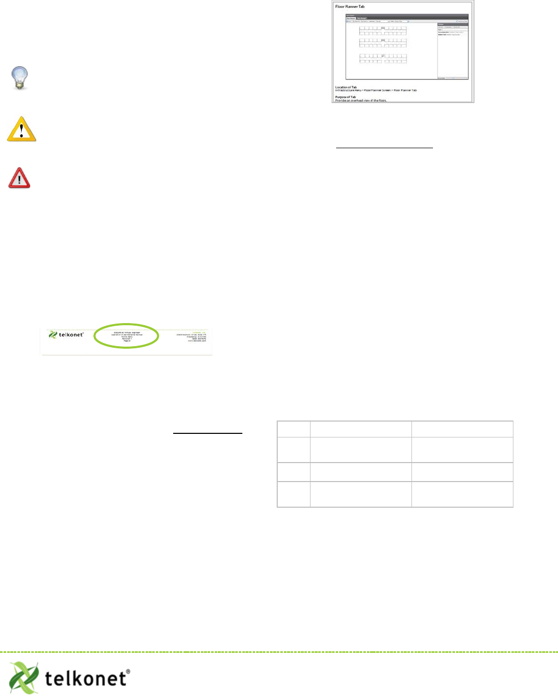
The EcoWave package is comprised of two hardware components as shown below. Together they form a
wireless programmable controllable thermostat. It can be easily installed on packaged terminal air
conditioners, fan coils, heat pumps, split systems, and more. With software-based relay control and fan speed
configuration, programming setup is simple and fast.
EcoTouch
• Display unit
• Place in optimum location for temperature measurement and
ease of occupant use
EcoSource
• HVAC Controller
• Install in or on HVAC unit
• Accepts association with 15 total compatible wireless devices
• Each compatible wireless device can be associated to
multiple EcoSources
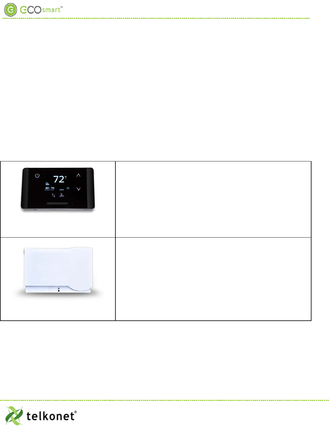
Accomodates a Variety of Configurations
EcoWave Featuring EcoTouch IO&M Guide Telkonet, Inc.
For Use with Firmware Version 2.x 20800 Swenson Drive, Suite 175
Waukesha, WI 53186
Revision 2 (800) 380-9640
Page 3 www.telkonet.com
EcoWave Package Overview
The EcoWave Package can be configured for many different HVAC
scenarios. For example:
One EcoTouch can control multiple HVAC systems, each equipped
with an EcoSource, but all directed by a single EcoTouch display
unit. This type of installation reduces the complexity of running
multiple HVAC units in a single large space and eliminating the
potential of opposing modes forcing equipment to compete
against each other.
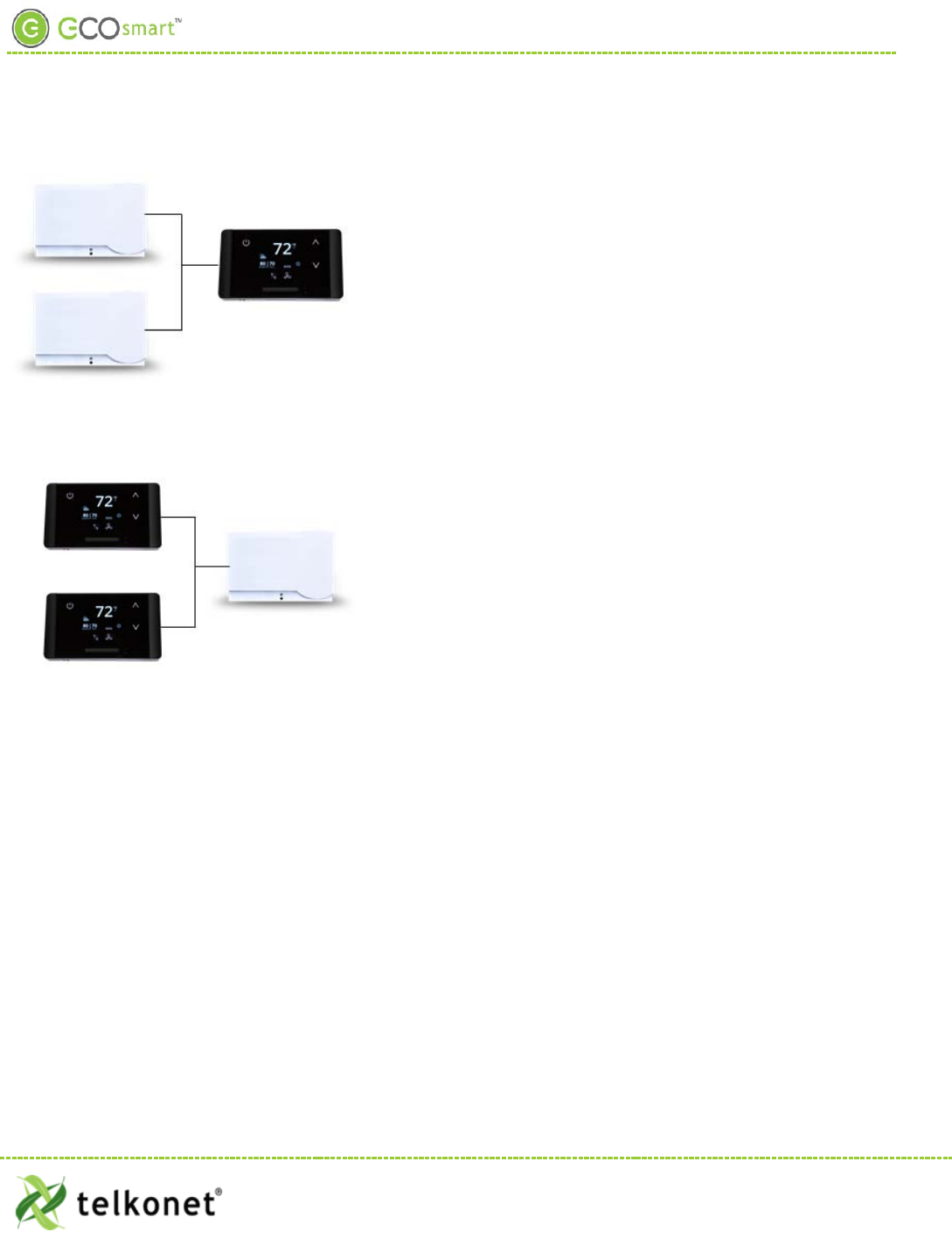
Multiple EcoTouches can control one HVAC system, equipped
with one EcoSource.
The wiring interface conforms to industry standards. Telkonet
can develop specific wiring diagrams, if a complete specification
is provided for the HVAC unit(s) in use at the site.
EcoWave Featuring EcoTouch IO&M Guide Telkonet, Inc.
For Use with Firmware Version 2.x 20800 Swenson Drive, Suite 175
Waukesha, WI 53186
Revision 2 (800) 380-9640
Page 4 www.telkonet.com
EcoSource Installation
EcoSource
Wiring
The EcoSource controller connects to the HVAC system via standard wiring conventions, using 12-277VAC
voltages supplied by the HVAC equipment. The EcoSource can accept three different power sources, which
assist in scenarios where different components (heat, fan) are powered by different voltages. This
simplifies installation on units such as fan coils.
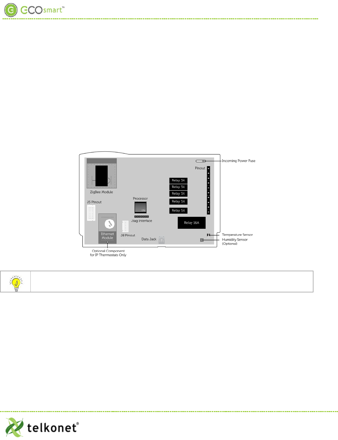
The EcoSource accepts standard thermostat wiring, typically 14-22 AWG. Wiring conventions follow
industry standards; however, it is important to note that the relay configuration is dynamic and can be
modified at the factory or in the field.
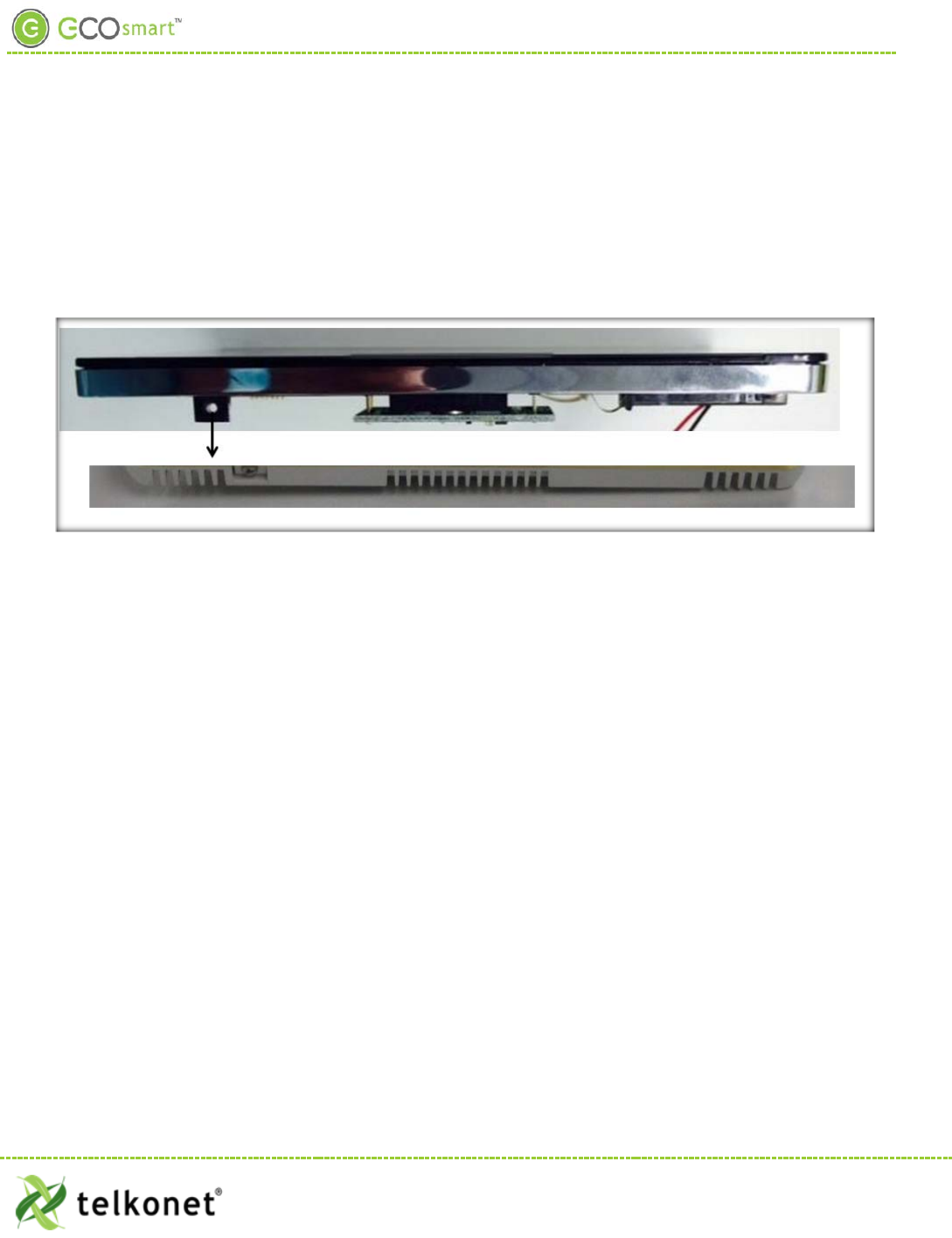
Figure 1: Internal View EcoSource
If the EcoSource will be mounted inside a metal HBSC unit or in a room with a large amount of metallic
equipment that may cause RF interference, an external antenna may be necessary.
EcoWave Featuring EcoTouch IO&M Guide Telkonet, Inc.
For Use with Firmware Version 2.x 20800 Swenson Drive, Suite 175
EcoSour ce Waukesha, WI 53186
Revision 2 (800) 380-9640
Page 5 www.telkonet.com

EcoSource Installation
High/Low Voltage Options
High Voltage Installation Option (page 6)
• High Voltage is defined as 48 volt or
greater.
• There are two installation options:
1) JBOX with Vertical Mud Ring Mount:
requires adapter plate as shown in
Figure 2.
2) Factory HVAC Mount
Low Voltage Installation Options (page 14)
• There are 3 options; select based on code
and desired look:
1) Drywall mount: no conduit required;
no JBOX adapter plate required.
2) JBOX with Vertical Mud Ring Mount:
requires adapter plate as shown in
Figure 2.
3) JBOX with Horizontal Mud Ring
Mount: requires wing nut, hole must
be drilled in backplate; no JBOX
plate required.
High Voltage Installation
(For Low Voltage Installation instructions, see page 14).
Mounting Preparation
The back plate type must be defined as low or high voltage prior to shipment.
EcoWave Featuring EcoTouch IO&M Guide Telkonet, Inc.
For Use with Firmware Version 2.x 20800 Swenson Drive, Suite 175
EcoSour ce Waukesha, WI 53186
Revision 2 (800) 380-9640
Page 6 www.telkonet.com
EcoSource High Voltage Installation
CAUTION!
• Weco terminal on-site wiring for high voltage installation is not allowed. You must use the pre-
shipped 16-guage wired backplate provided by Telkonet.
• High voltage installation should only be performed by a qualified heating & air conditioning
contractor or licensed electrician.
• Failure to understand and follow all instructions carefully before installing or operating this
device could cause personal injury and/or property damage.
• All wiring must conform to local and national electrical ordinances and codes.
• Prevent electrical shock, personal injury, and equipment damage: prior to installation or
service, disconnect system’s electric power at main fuse or circuit breaker box.
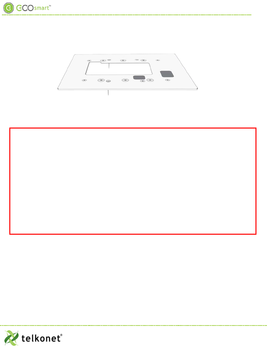
Figure 2: Telkonet JBOX Adapter Plate
For all high voltage installations a single gang mud ring must be mounted VERTICALLY on a JBOX. A Telkonet
JBOX Adapter Plate (see Figure 2) is required for all JBOX installations.
EcoSource High Voltage Required Equipment
• EcoSource (P/N: SS6500)
• EcoTouch (P/N: SS6560)
• High Voltage Backplate
• Telkonet High Voltage JBOX Adapter
• Two #6-32 1” screws
• Four #5 ½” coarse thread screws
• Voltmeter
• Level
• Phillips screwdriver
• UL rated insulating tape
• Wire stripper
• Wire cutter
• Wire nuts
EcoWave Featuring EcoTouch IO&M Guide Telkonet, Inc.
For Use with Firmware Version 2.x 20800 Swenson Drive, Suite 175
EcoSour ce Waukesha, WI 53186
Revision 2 (800) 380-9640
Page 7 www.telkonet.com
EcoSource High Voltage Installation
Installation Steps
Step 1 Ensure the JBOX has been installed with a vertical single gang mud ring. See Figure 3.
Figure 3: Vertical Single Gang Mud Ring
Step 2 Turn off power at EcoSource or mounting location using a disconnect switch or breaker
lockout/tag out on appropriate breaker panel.
Step 3 Test that power is off by using a voltmeter.
Step 4 Strip the LINE wire back 0.25 inches.
Step 5 Cap the LINE wire with a wire nut or electrical tape.
Step 6 Cut the COMMON wire so the copper is flush with the insulation.
Step 7 Strip all wires except for COMMON back 0.25 inches.
Reminder: For all high voltage installations, a single gang mud ring must be mounted
VERTICALLY.
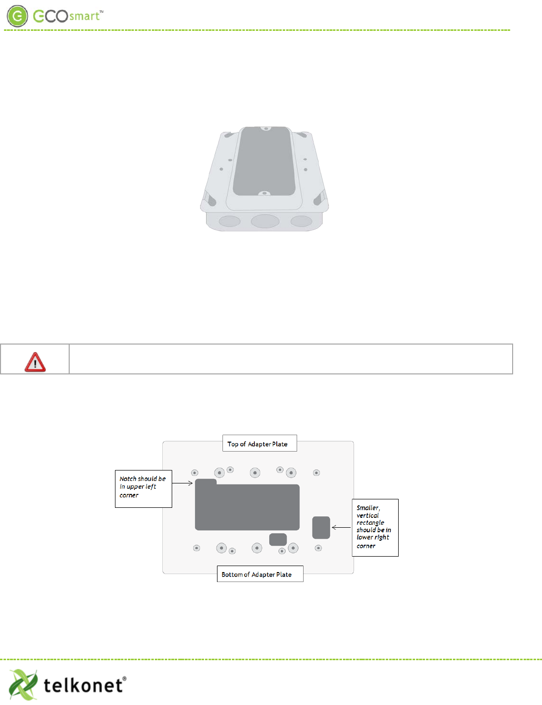
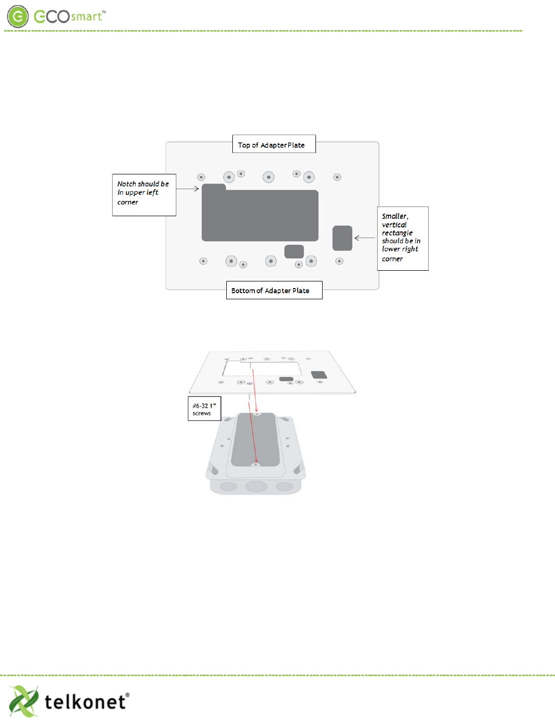
Step 8 Determine which end of the adapter plate should be installed as the top, and which end should
be installed as the bottom. As shown in Figure 4, the notch in the main display should be in the
upper left corner, and the smaller, vertical rectangle should be in the lower right corner.
Figure 4: Determine Top & Bottom of Plate
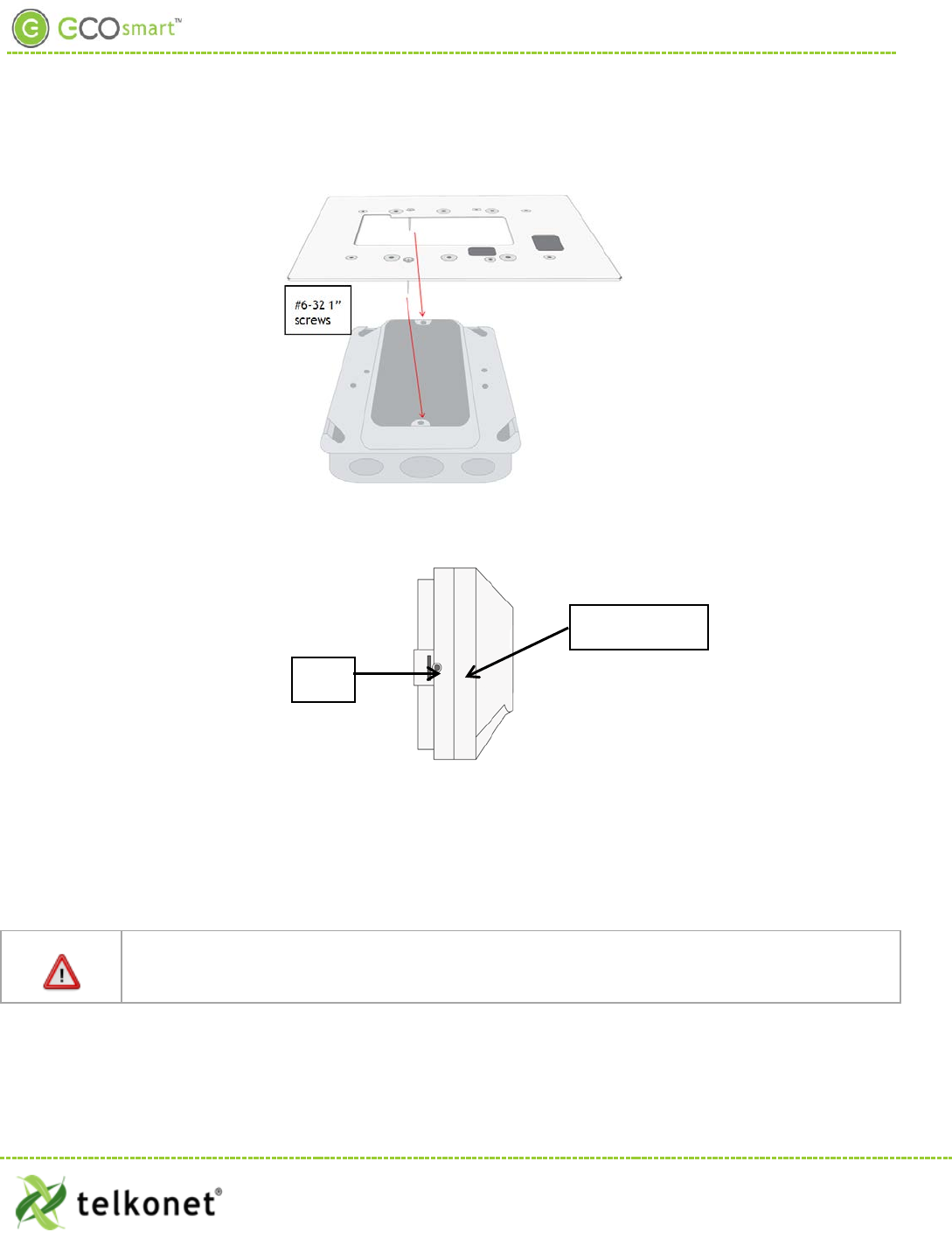
Step 9 Level the high voltage Telkonet JBOX adapter plate and mount to the mud ring with two #6-32
1” screws. See Figure 5.
EcoWave Featuring EcoTouch IO&M Guide Telkonet, Inc.
For Use with Firmware Version 2.x 20800 Swenson Drive, Suite 175
EcoSour ce Waukesha, WI 53186
Revision 2 (800) 380-9640
Page 8 www.telkonet.com
EcoSource High Voltage Installation
Figure 5: JBOX, Mud Ring, Adapter Plate
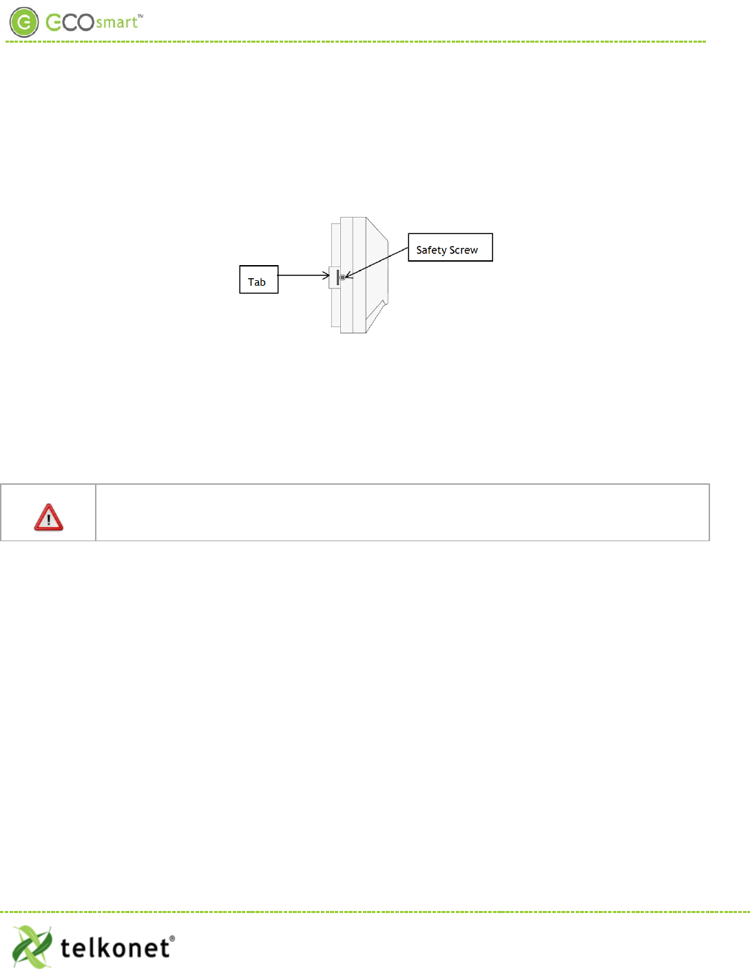
Step 10 Remove the safety screw from the left side of the thermostat using the hex wrench. See Figure
6.
Figure 6: EcoSource Side View
Step 11 Separate the high voltage back plate from the thermostat: Use a flathead screwdriver to
GENTLY press the tab next to the screw hole to allow the thermostat to pop open.
WARNING: Using too much force can break the tab.
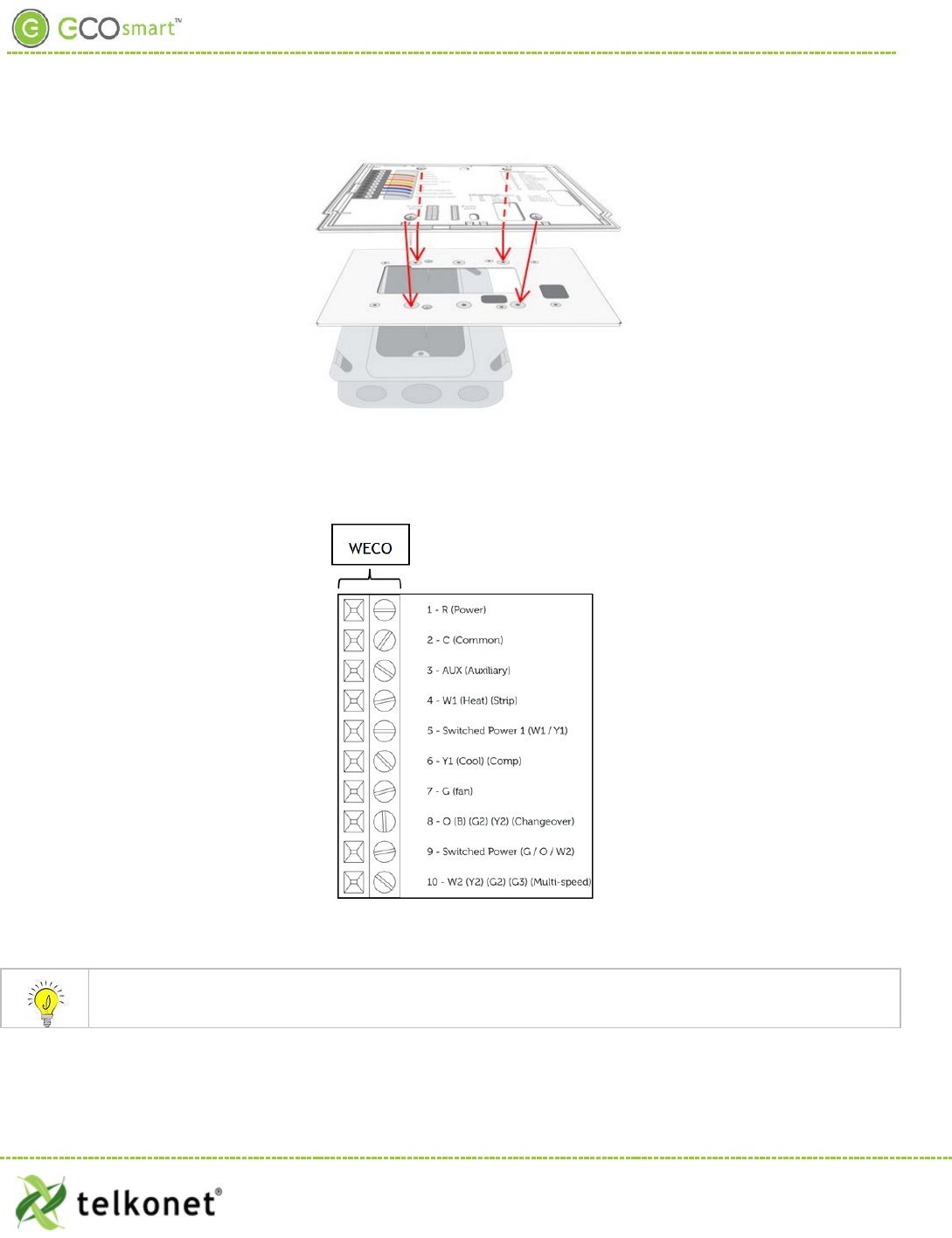
Step 12 Place thermostat backplate against the JBOX adapter plate. The adapter plate and backplate
holes should align if both are correctly oriented.
Thermostat wiring cannot touch or be placed in close proximity to the J7 pins! This can occur if
the wiring enters the thermostat from the J8 hole and is placed diagonally, directly over the J7
pins.
Step 13 Connect each 16-gauge wire (pre-installed on the thermostat’s high-voltage back plate) to the
matching functional wire within the JBOX, using appropriately sized wire nuts or a NEC-
Safety Screw
Tab
EcoWave Featuring EcoTouch IO&M Guide Telkonet, Inc.
For Use with Firmware Version 2.x 20800 Swenson Drive, Suite 175
EcoSour ce Waukesha, WI 53186
Revision 2 (800) 380-9640
Page 9 www.telkonet.com
EcoSource High Voltage Installation
approved electrical connection inside the junction box. If a site-specific wiring diagram was
provided, refer to this for wiring. If no diagram was provided, refer to Figure 7.
. (If controlling proportional valve or ECM fan, see Appendix A.) Any unused wires must be capped according
to NEC standards.1
For variable output connections, see Appendix A on page 39.
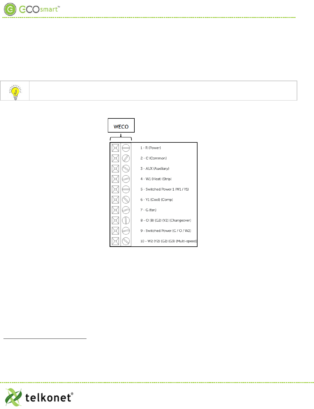
Figure 7: Wiring
1 The High Voltage backplate comes with R, Switched Power 1 and Switched Power 2 jumped together with a Red Wire nut. These can be
connected to the same power source assuming all controlled Fans and Valves will be controlled at the same voltage that will be powering
the thermostat. If a different voltage will be used for any of the Controlled elements of the HVAC then the appropriate power source
should be connected to the Switched Power 1 (W1,Y1) and Switched Power 2 (G,O,W2) terminals.
EcoWave Featuring EcoTouch IO&M Guide Telkonet, Inc.
For Use with Firmware Version 2.x 20800 Swenson Drive, Suite 175
EcoSour ce Waukesha, WI 53186
Revision 2 (800) 380-9640
Page 10 www.telkonet.com
EcoSource High Voltage Installation
Table 1-Wiring:
Pin Label on Backplate Function
1 R (Power) 12-277VAC power from HVAC, used to power the thermostat
2 C (Common) AC Common
3 AUX (Auxiliary) User defined
4 W1 (Heat) (Strip) Heat call or strip heat call (depends on programming)
5 Switched Power 1 (W1/Y1) Provides alternate power for W1 and Y1
6 Y1 (Cool) (Comp) Cool/Compressor call
7 G (Fan) Fan Call - Low speed
8 O (B) (G2) (Y2) (Changeover)
Multi-use - depends on programming and site requirements:
• Changeover
• 2nd Stage Fan
•
2
nd
Stage Cooling
9
Switched Power 2
Provides alternate power for G, O, and W2
10 W2 (Y2) (G2) (G3) (Multi-speed)
Multi-use - depends on programming and site requirements:
• 2nd stage heat
• Electric heat (for HPs with strip heat, etc.)
•
Emergency heat
Step 14 Carefully push the wired connections back into the JBOX.
Step 15 Mount pre-wired 16 gauge SS6000 backplate on top of JBOX adapter, using four #5 ½” coarse
thread screws. See Figure 8.
Figure 8: Backplate on Adapter Plate
Step 16 Ensure no airflow from JBOX or wall cavity is able to seep into the thermostat through the wire
harness. Telkonet recommends the use of UL caulk or UL rated insulating tape as shown in
Figure 9 to avoid false temperature readings.
EcoWave Featuring EcoTouch IO&M Guide Telkonet, Inc.
For Use with Firmware Version 2.x 20800 Swenson Drive, Suite 175
EcoSour ce Waukesha, WI 53186
Revision 2 (800) 380-9640
Page 11 www.telkonet.com
EcoSource High Voltage Installation
Figure 9: Backplate with UL-Rated Insulating Tape
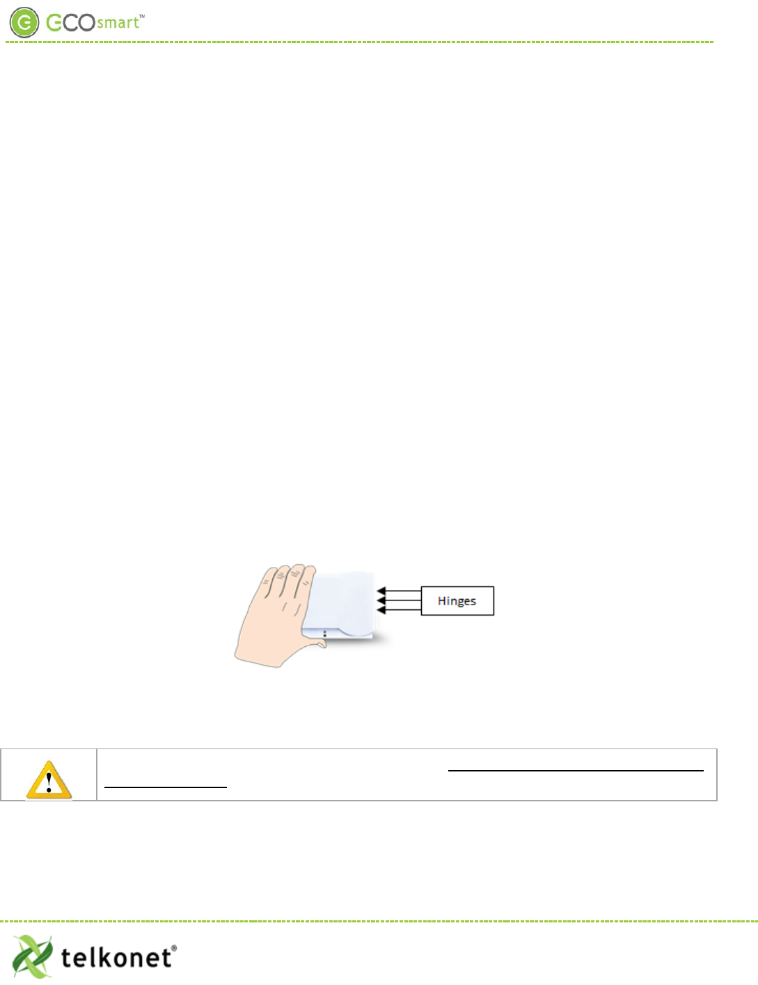
Step 17 Line up the hinges on the thermostat to the notches on the backplate:
Figure 10-Line Up Hinges on Right
Step 18 Press the right side of the thermostat tightly against the back plate.
Step 19 Slowly bring the left side toward the wall. Use care not to force the faceplate closed. If you
encounter resistance, check to make sure no wires are pinched between components.
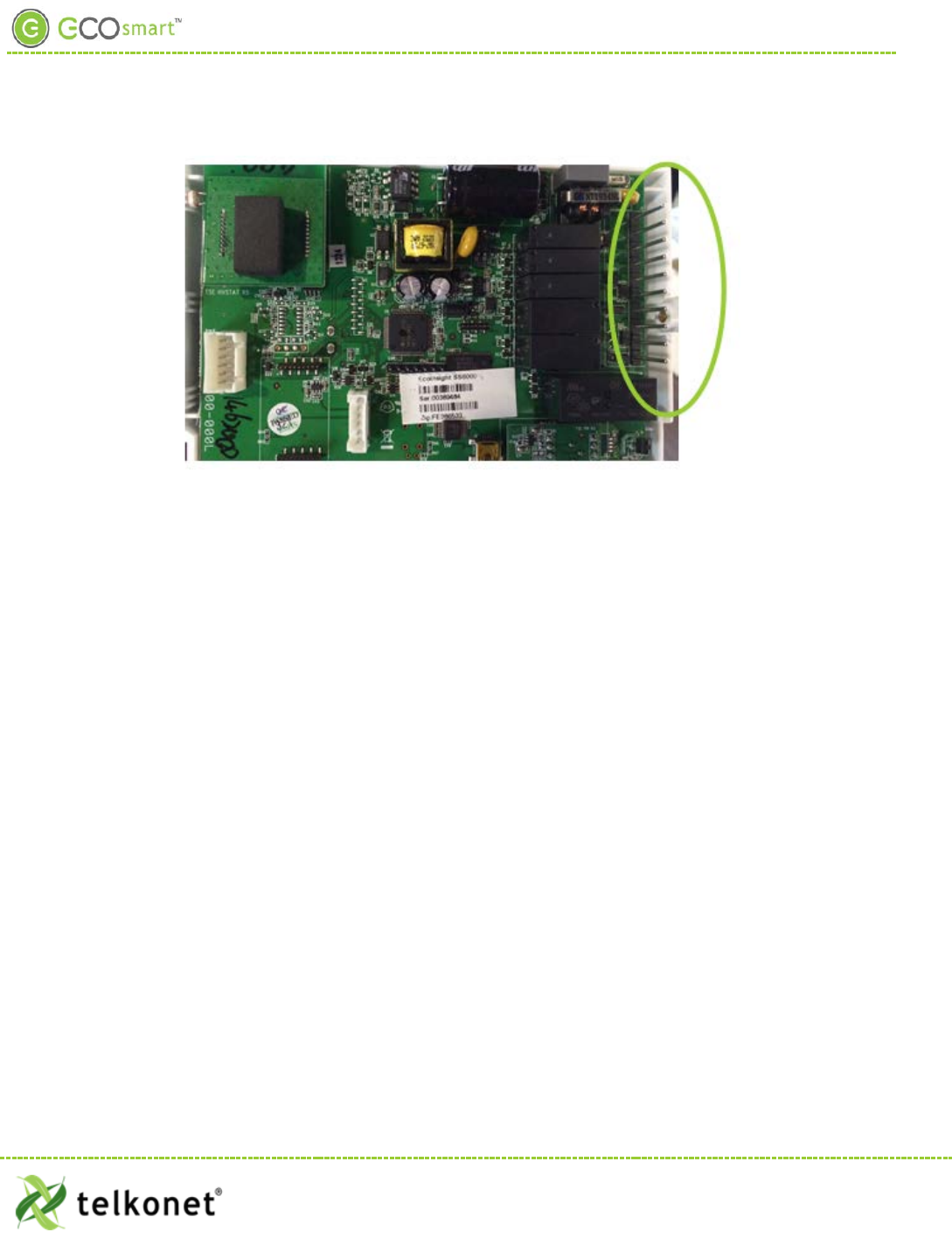
Caution: the metal pins (as shown in Figure 11) can be bent when replacing faceplates if too
much force is used.
EcoWave Featuring EcoTouch IO&M Guide Telkonet, Inc.
For Use with Firmware Version 2.x 20800 Swenson Drive, Suite 175
EcoSour ce Waukesha, WI 53186
Revision 2 (800) 380-9640
Page 12 www.telkonet.com
EcoSource High Voltage Installation
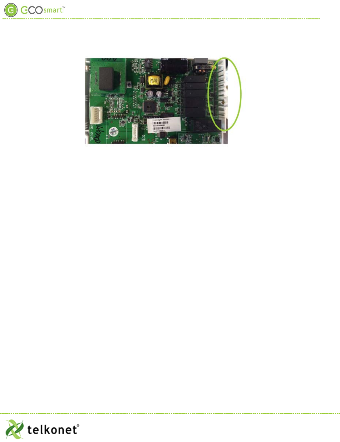
Figure 11: Metal Pins
Step 20 Return the electrical circuit to operation. Remove all lockouts or tags from the circuit breaker
and enable any disconnects.
Step 21 Verify the EcoSource thermostat display is active.
Step 22 Test all components to make sure that you can engage both the heat and air conditioning, and
all supported fan settings (high, low, etc.). Wiring is complete.
Step 23 Once the thermostat has been snapped onto the backplate, use a hex wrench to insert the
safety screw.
EcoWave Featuring EcoTouch IO&M Guide Telkonet, Inc.
For Use with Firmware Version 2.x 20800 Swenson Drive, Suite 175
EcoSour ce Waukesha, WI 53186
Revision 2 (800) 380-9640
Page 13 www.telkonet.com
EcoSource Low Voltage Installation
Low Voltage Installation
Always ensure power has been turned off before starting installation.
EcoSource Low Voltage Required Equipment
• EcoSource (P/N: SS6500)
• EcoTouch (P/N: SS6560)
• Voltmeter
• Level
• Phillips Head Screwdriver
• Precision Screwdriver
• UL rated insulating tape
• Wire stripper
• Wire nuts
Additional Hardware Required for Drywall Mount
• Four 50 lb. EZ-Lock anchors and provided screws
Additional Hardware Required for VERTICAL JBOX Mount
• Telkonet JBOX Adapter Plate
• Two #6-32 1” screws
• Four $5 ½” coarse thread screws
Additional Hardware Required for HORIZONTAL JBOX Mount
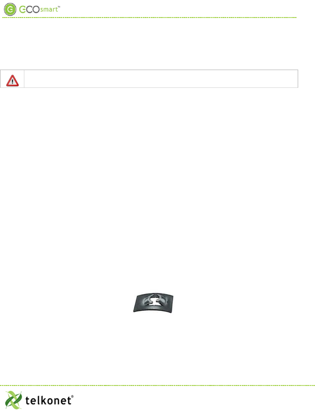
• Two #6-32 1” screws
• 1 Speed Nut (flat-type speed nut fastener that accommodates a #6-32 1” screw as shown in Figure
12.
Figure 12-Speed Nut
Installation Instructions Common to All Three Low Voltage Options
Step 1 If applicable, determine the location in the room where the thermostat will be installed. (See
EcoTouch Thermostat Location Planning section, page 24.)
EcoWave Featuring EcoTouch IO&M Guide Telkonet, Inc.
For Use with Firmware Version 2.x 20800 Swenson Drive, Suite 175
EcoSour ce Waukesha, WI 53186
Revision 2 (800) 380-9640
Page 14 www.telkonet.com
EcoSource Low Voltage Installation
Step 2 Turn off power at EcoSource mounting location using a disconnect switch or breaker lockout/tag
out on appropriate breaker panel.
Step 3 Test that power is off by using a voltmeter.
Step 4 Remove the safety screw from the left side of the thermostat using the hex wrench. See Figure
13.
Figure 13: EcoSource Side View
Step 5 Separate the backplate from the thermostat: Use a flathead screwdriver to GENTLY press the
tab next to the screw hole to allow the thermostat to pop open. WARNING: Using too much
force can break the tab.
Step 6 For drywall mounting instructions, go to Step 7.
For JBOX vertical installation instructions, go to Step 19
For JBOX horizontal installation instructions, go to Step 30
Thermostat wiring cannot touch or be placed in close proximity to the J7 pins! This can occur if
the wiring enters the thermostat from the J8 hole and is placed diagonally, directly over the J7
pins.
Drywall Mounting Instructions
• Requires four 50 lb. EZ-Lock anchors and provided screws
Step 7 Hold backplate against wall at appropriate height. Using a pen, level-mark your 4 holes.
Step 8 Use appropriate drill for anchor and insert anchors into holes.
Step 9 Screw backplate to the wall and into the anchors. Re-check that it is still level.
Step 10 Strip the LINE wire back 0.25 inches.
Step 11 Cap the LINE wire with a wire nut or electrical tape.
Step 12 Cut the COMMON wire so the copper is flush with the insulation.
Step 13 Strip all wires except for COMMON back 0.25 inches.
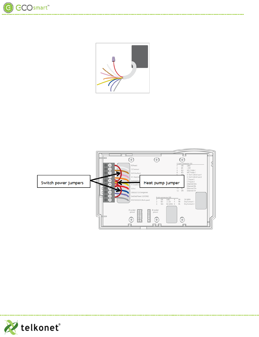
Step 14 Verify the wiring now looks similar to Figure 14.
EcoWave Featuring EcoTouch IO&M Guide Telkonet, Inc.
For Use with Firmware Version 2.x 20800 Swenson Drive, Suite 175
EcoSour ce Waukesha, WI 53186
Revision 2 (800) 380-9640
Page 15 www.telkonet.com
EcoSource Low Voltage Installation
Figure 14-Wiring
Step 15 Starting at the bottom of the terminal block and working up, use a precision screwdriver to
secure each of the wires into the appropriate pins on the terminal block. Low voltage only:
Using 20-18 gauge wire, leave a minimum of 8” of spare wire exposed from the wall for
connection directly to the thermostat’s back plate screw terminals.
Step 16 Low voltage only: Ensure backplate has appropriate jumpers between R, SW1 and SW2. If
installing on a heat pump, ensure there is a jumper between Y1 and W1. See Figure 15.
Figure 15: EcoSource Backplate with Appropriate Jumpers
Step 17 Verify each wire is secure by gently tugging on it.
Step 18 Continue to Step 41
JBOX Using Vertical Mud Ring Instructions
• Requires Telkonet JBOX Adapter Plate and two #6-32 1” screws
Step 19 Strip the LINE wire back 0.25 inches.
Step 20 Cap the LINE wire with a wire nut or electrical tape.
Step 21 Cut the COMMON wire so the copper is flush with the insulation.
Step 22 Strip all wires except for COMMON back 0.25 inches.
EcoWave Featuring EcoTouch IO&M Guide Telkonet, Inc.
For Use with Firmware Version 2.x 20800 Swenson Drive, Suite 175
EcoSour ce Waukesha, WI 53186
Revision 2 (800) 380-9640
Page 16 www.telkonet.com
EcoSource Low Voltage Installation
Step 23 Determine which end of the adapter should be situated on top, and which end should be
situated on the bottom. As shown in Figure 16, the notch in the main display should be in the
upper left corner, and the smaller, vertical rectangle should be in the lower right corner.
Figure 16: Determine Top & Bottom of Plate
Step 24 Mount the Telkonet JBOX adapter plate to the mud ring with two #6-32 1” screws. See Figure
17.
Figure 17: JBOX, Mud Ring & Adapter Plate
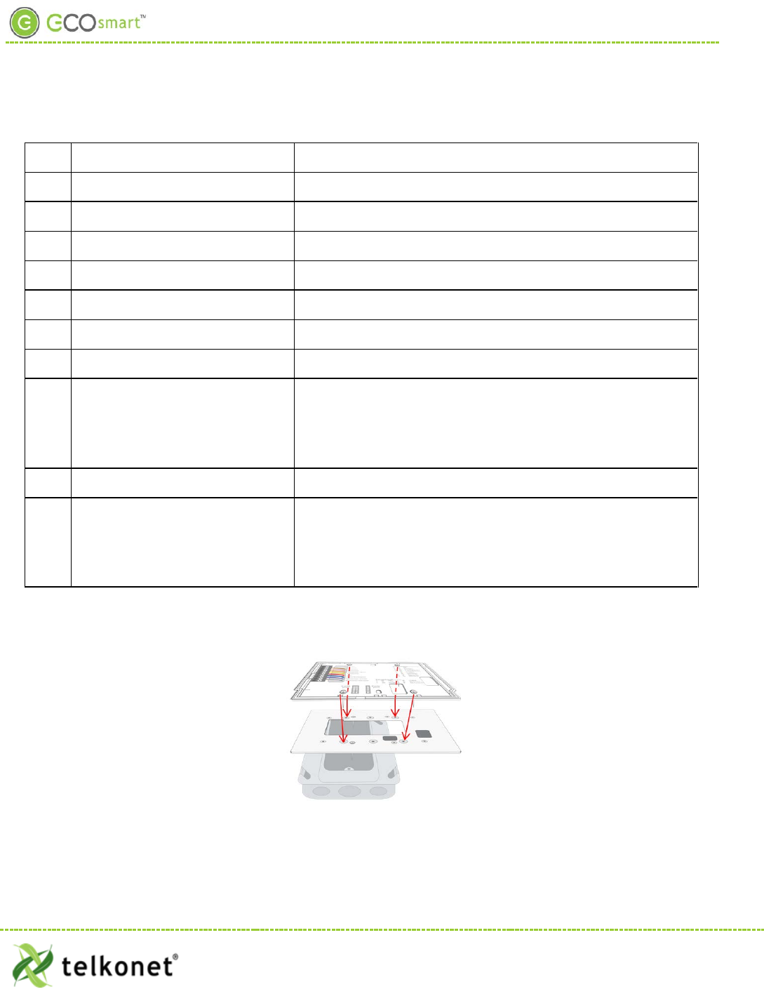
Step 25 Mount SS6000 backplate on top of JBOX adapter, using four #5 ½” coarse thread screws. See
Figure 18.
EcoWave Featuring EcoTouch IO&M Guide Telkonet, Inc.
For Use with Firmware Version 2.x 20800 Swenson Drive, Suite 175
EcoSour ce Waukesha, WI 53186
Revision 2 (800) 380-9640
Page 17 www.telkonet.com
EcoSource Low Voltage Installation
Figure 18: Back Plate on Adapter Plate
Step 26 Connect each WECO terminal to the matching functional wire within the JBOX. Refer to Figure
19 and Table 2. (If controlling proportional valve or ECM fan, see Appendix A.) Any unused wires
must be capped according to NEC standards.
Figure 19: Wiring
For variable output connections, see Appendix A on page 39.
EcoWave Featuring EcoTouch IO&M Guide Telkonet, Inc.
For Use with Firmware Version 2.x 20800 Swenson Drive, Suite 175
EcoSour ce Waukesha, WI 53186
Revision 2 (800) 380-9640
Page 18 www.telkonet.com

EcoSource Low Voltage Installation
Table 2: Wiring
Pin
Label on Backplate
Function
1
R (Power)
12-277VAC power from HVAC, used to power the thermostat
2 C (Common) AC Common
3
AUX (Auxiliary)
User defined
4
W1 (Heat) (Strip)
Heat call or strip heat call (depends on programming)
5 Switched Power 1 (W1/Y1) Provides alternate power for W1 and Y1
6
Y1 (Cool) (Comp)
Cool/Compressor call
7
G (Fan)
Fan Call - Low speed
8 O (B) (G2) (Y2) (Changeover)
Multi-use - depends on programming and site requirements:
• Changeover
• 2nd Stage Fan
• 2nd Stage Cooling
9 Switched Power 2 Provides alternate power for G, O, and W2
10 W2 (Y2) (G2) (G3) (Multi-speed)
Multi-use - depends on programming and site requirements:
• 2nd stage heat
• Electric heat (for HPs with strip heat, etc.)
• Emergency heat
Step 27 Low voltage only: ensure backplate has appropriate jumpers between R, SW1 and SW2. If
installing on a heat pump, ensure there is a jumper between Y1 and W1. See Figure 15 on page
16.
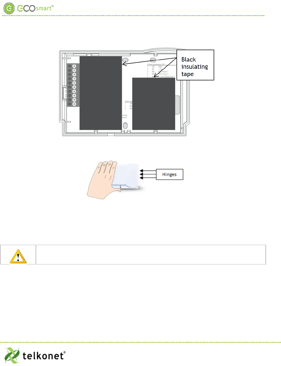
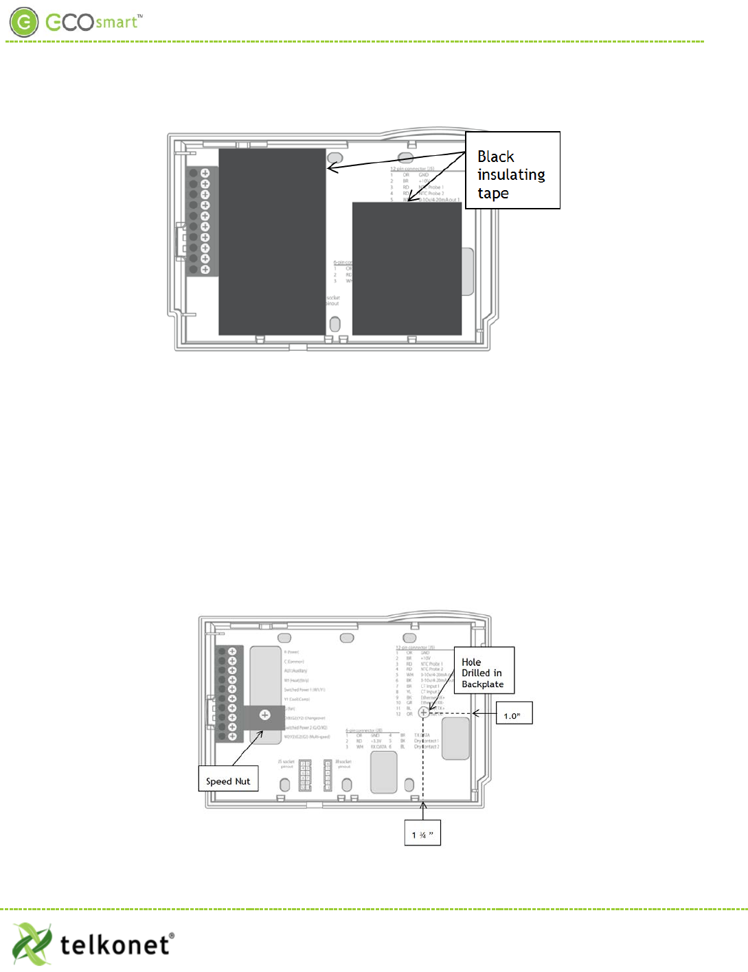
Step 28 Ensure no airflow from the JBOX or wall cavity is able to seep into the thermostat through the
wire harness. Telkonet recommends the use of UL approved caulk or UL rated insulating tape to
avoid false temperature readings. Figure 20 illustrates sections of insulating tape on the
backplate, covering the wall opening.
Step 29 Continue to Step 41
EcoWave Featuring EcoTouch IO&M Guide Telkonet, Inc.
For Use with Firmware Version 2.x 20800 Swenson Drive, Suite 175
EcoSour ce Waukesha, WI 53186
Revision 2 (800) 380-9640
Page 19 www.telkonet.com
EcoSource Low Voltage Installation
Figure 20: EcoSource Backplate with UL-Rated Insulating Tape
JBOX Using Horizontal Mud Ring Instructions
Requires:
• Speed nut that accommodates a #6-32 1” screw.
• two #6-32 1-inch screws
• 1 hole to be drilled into backplate (drilling performed onsite or by Telkonet Production prior to
shipping if requested in advance.)
Step 30 Ensure the JBOX has been installed with a horizontal mud ring.
Step 31 Unless this was done prior to shipping, drill a hole in backplate as shown in Figure 21. The
horizontal distance between the hole and the inner right side of the plate should be 1.0”. The
vertical distance between the hole and the inner right side of the plate should be 1 ¾”. The
hole should accommodate a #6-32 1” screw.
(Preferred method for low voltage new construction)
EcoWave Featuring EcoTouch IO&M Guide Telkonet, Inc.
For Use with Firmware Version 2.x 20800 Swenson Drive, Suite 175
EcoSour ce Waukesha, WI 53186
Revision 2 (800) 380-9640
Page 20 www.telkonet.com
EcoSource Low Voltage Installation
Figure 21: EcoSource Backplate with Speed Nut and Drilled Hole
Step 32 Level the backplate using a pen level across the bottom of the backplate.
Step 33 Place the speed nut on the backplate in the position shown in Figure 21, with the prongs
pointing inward toward the mud ring.
Step 34 Place the screw in the speed nut hole.
Step 35 Drive the screw into the mud ring. Use your fingers to hold the speed nut in place, to prevent it
from turning as the screw is driven. (The curve of the speed nut allows the head of the screw to
be slightly recessed into the backplate.)
Step 36 Mount the other screw in the hole on the right side of the backplate.
Step 37 Starting at the bottom of the terminal block and working up, use a precision screwdriver to
secure each of the wires into the appropriate pins on the terminal block. For low voltage, using
20-18 gauge wire, leave a minimum of 8” of wire exposed from the wall for connection directly
to the thermostat’s backplate WECO terminals.
Step 38 Low voltage only: Ensure backplate has appropriate jumpers between R, SW1 and SW2. If
installing on a heat pump, ensure there is a jumper between Y1 and W1. See Figure 15 on page
16.
Step 39 Verify each wire is secure by gently tugging on it.
Step 40 Ensure no airflow from the JBOX or wall cavity is able to seep into the thermostat through the
wire harness. Telkonet recommends the use of UL caulk or UL rated insulating tape to avoid
false temperature readings. Figure 20 on page 20 illustrates sections of insulating tape on the
backplate, covering the wall opening.
Instructions Common to All Three Low Voltage Options
Step 41 Hook the thermostat to the hinges on the right side of the backplate, as shown Figure 22.
Figure 22-Line Up Hinges on Right
Step 42 Line up the hinges on the thermostat to the notches on the backplate. Press the right side of
the thermostat tightly against the back plate.
Caution: when replacing thermostats, the metal pins (as shown in Figure 23) can be bent if too
much force is used.
EcoWave Featuring EcoTouch IO&M Guide Telkonet, Inc.
For Use with Firmware Version 2.x 20800 Swenson Drive, Suite 175
EcoSour ce Waukesha, WI 53186
Revision 2 (800) 380-9640
Page 21 www.telkonet.com
EcoSource Low Voltage Installation
Figure 23: Metal Pins-Use Care
Step 43 Slowly bring the left side toward the wall as shown. Use care not to force the faceplate closed.
If you encounter resistance, ensure no wires are pinched between components and that no pins
are bent.
Step 44 Once the thermostat has been snapped onto the back plate, use a hex wrench to insert the
safety screw in the location shown in Figure 13 on page 15.
Step 45 Inside the PTAC, verify the GFI (if so equipped) has not been tripped.
Step 46 Verify that the PTAC has been set to Class II (remote thermostat) operation (if applicable).
Consult PTAC manual for proper procedure.
Step 47 Reinsert and tighten the safety screw on the EcoSource.
Step 48 Remove all lockouts or tags from the circuit breaker.
Step 49 Return the electrical circuit to operation.
Step 50 Verify the thermostat display is active.
Step 51 Test all components to make sure that you can engage both the heat and air conditioning, and
all supported fan settings (high, low, etc.). Wiring is complete.
Step 52 Continue to EcoTouch Wireless Installation section.
Relay Configuration
The thermostat comes with a default relay configuration, which sets the functions of each pin. This default can
be changed to one of several alternate relay configurations, which are stored in the memory of the thermostat.
To change your thermostat relay configuration, specifically command #2.
J5 Connector
The functions of the J5 Connector will vary based on the device model.
EcoWave Featuring EcoTouch IO&M Guide Telkonet, Inc.
For Use with Firmware Version 2.x 20800 Swenson Drive, Suite 175
EcoSour ce Waukesha, WI 53186
Revision 2 (800) 380-9640
Page 22 www.telkonet.com
EcoSource Low Voltage Installation
Table 3: J5 Connector Pinout
Pin Wire Color Label on Backplate Function
1 OR GND Thermostat Signal Ground (not
an earth ground)
2 BR +10V 10 Volts DC Output
3 RD NTC Probe 1 Temperature Probe 1
4 RD NTC Probe 1 Temperature Probe 2
5 * WH 0-10v/4-20mA out 1 Analog Output #1 (VO model
only)
6 * BK 0-10v/4-20mA out 2 Analog Output #2 (VO model
only)
7 BR CT Input 1 Current Transformer Input for
Amperage
8 YL CT Input 1 Current Transformer Input for
Amperage
9 † BK CT input 2 Current Transformer Input for
Amperage
10 † GR CT input 2 Current Transformer Input for
Amperage
11 † BL CT input 3 Current Transformer Input for
Amperage
12 † OR CT input 3 Current Transformer Input for
Amperage
EcoWave Featuring EcoTouch IO&M Guide Telkonet, Inc.
For Use with Firmware Version 2.x 20800 Swenson Drive, Suite 175
EcoSour ce Waukesha, WI 53186
Revision 2 (800) 380-9640
Page 23 www.telkonet.com
EcoTouch Installation
EcoTouch
The EcoTouch is a remote thermostat that communicates with the EcoSource via the wireless ZigBee mesh
network. It comes with a built-in temperature sensor and IR occupancy sensor. An optional humidity sensor
may also have been installed into the EcoTouch.
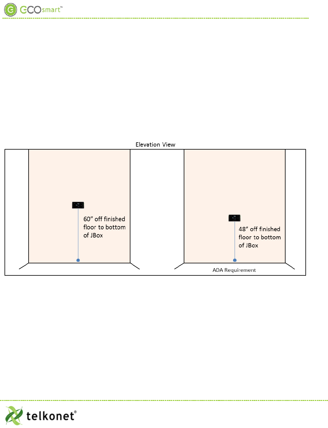
EcoTouch Location Planning
Actual thermostat mounting height can vary between sites depending upon furnishings and aesthetic
considerations. The standard recommended height is approximately 60” from finished floor. Any rooms
designated as ADA should be mounted above 15” and below 48”. See Figure 24.
Figure 24: Mounting Height
EcoWave Featuring EcoTouch IO&M Guide Telkonet, Inc.
For Use with Firmware Version 2.x 20800 Swenson Drive, Suite 175
EcoTouch Waukesha, WI 53186
Revision 2 (800) 380-9640
Page 24 www.telkonet.com

EcoTouch Installation
Table 4: EcoTouch Mounting-Best Practices
Mounting
Considerations
Best Practice
Distance to
Occupant
If the occupants will likely be stationary…
(e.g. sleeping in bed)
Position within 0 – 9 feet of their expected
location.
If the occupants will move occasionally…
(e.g. working at desk)
EcoTouch: within 9-18 feet of their
expected location
If the occupants will move regularly…
(e.g. walking in hall)
EcoTouch: within 18-25 feet of their
expected location
Line of Sight
Should not have its line of sight to the EcoSource partially obstructed by grills, registers, or
spinning fan blades.
EcoTouch has 140° wide horizontal viewing angle
Should point toward main sleeping area
If no door contacts or remote occupancy sensors are used in the guest room then the bed
should always be positioned within a 12’ radius from the front of the thermostat
Other
Considerations
Should be mounted on a wall away from heat or cold sources that could affect its
temperature reading. This includes direct sunlight, outside-facing walls with poor insulation,
walls with hot and cold riser piping, and walls near radiators.
Where possible, mount on an inside wall.
If a suitable location without a heat or cold source is not available, contact a Telkonet
Project Manager.
Should be mounted on the wall, not set into the wall. This will ensure that the backplate
provides proper airflow.
EcoWave Featuring EcoTouch IO&M Guide Telkonet, Inc.
For Use with Firmware Version 2.x 20800 Swenson Drive, Suite 175
EcoTouch Waukesha, WI 53186
Revision 2 (800) 380-9640
Page 25 www.telkonet.com
EcoTouch Installation
Installation
EcoTouch can accept 24VAC or 12-14VDC on J2.
Use wire harnesses with red and black stripped wires and JARD J4021F transformers, both provided
by Telkonet. (Exceptions may apply in certain circumstances.)
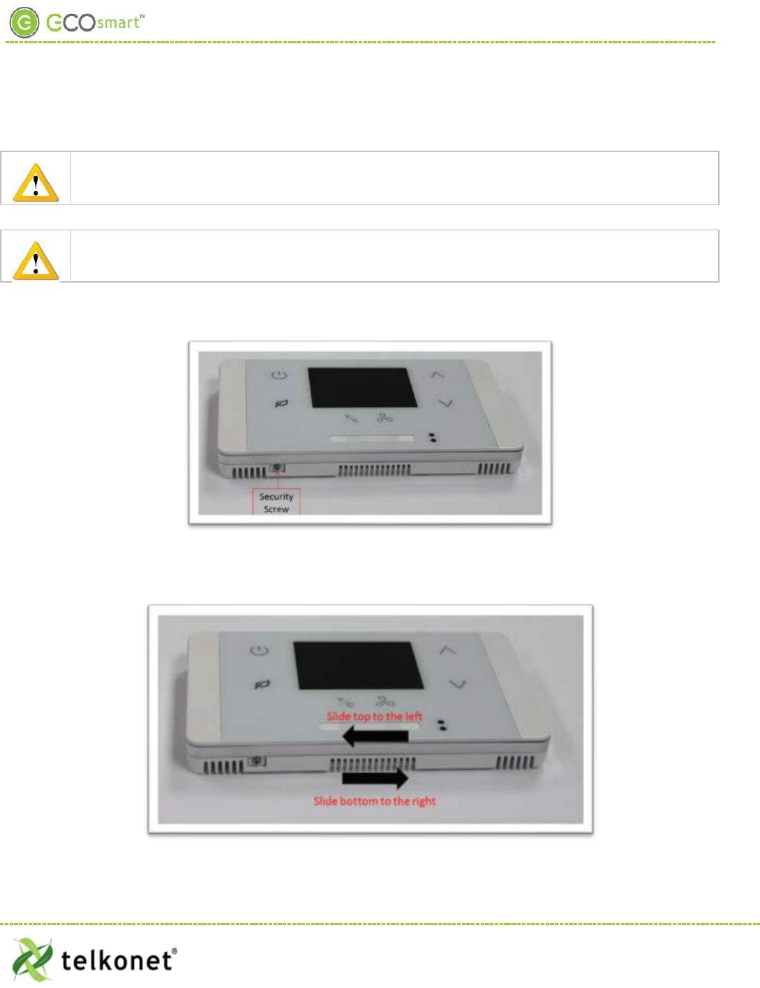
Step 1 Review table on page 25 to determine where the EcoTouch will be mounted.
Step 2 Remove the security screw from the EcoTouch (see Figure 25).
Figure 25-Security Screw
Step 3 Separate the backplate from the EcoTouch by sliding the backplate to the right and the front
plate to the left (approximately ¼ inch), as shown in Figure 26.
Figure 26: Slide Top Left, Bottom Right
EcoWave Featuring EcoTouch IO&M Guide Telkonet, Inc.
For Use with Firmware Version 2.x 20800 Swenson Drive, Suite 175
EcoTouch Waukesha, WI 53186
Revision 2 (800) 380-9640
Page 26 www.telkonet.com
EcoTouch Installation
Step 4 Lift the front plate up and off of the back plate as shown in Figure 27.
Figure 27: Lift Up and Off
Step 5 Level the backplate on the wall.
Step 6 Mark the placement for the mounting screws.
Step 7 Mount the backplate to the wall using the mounting screws.
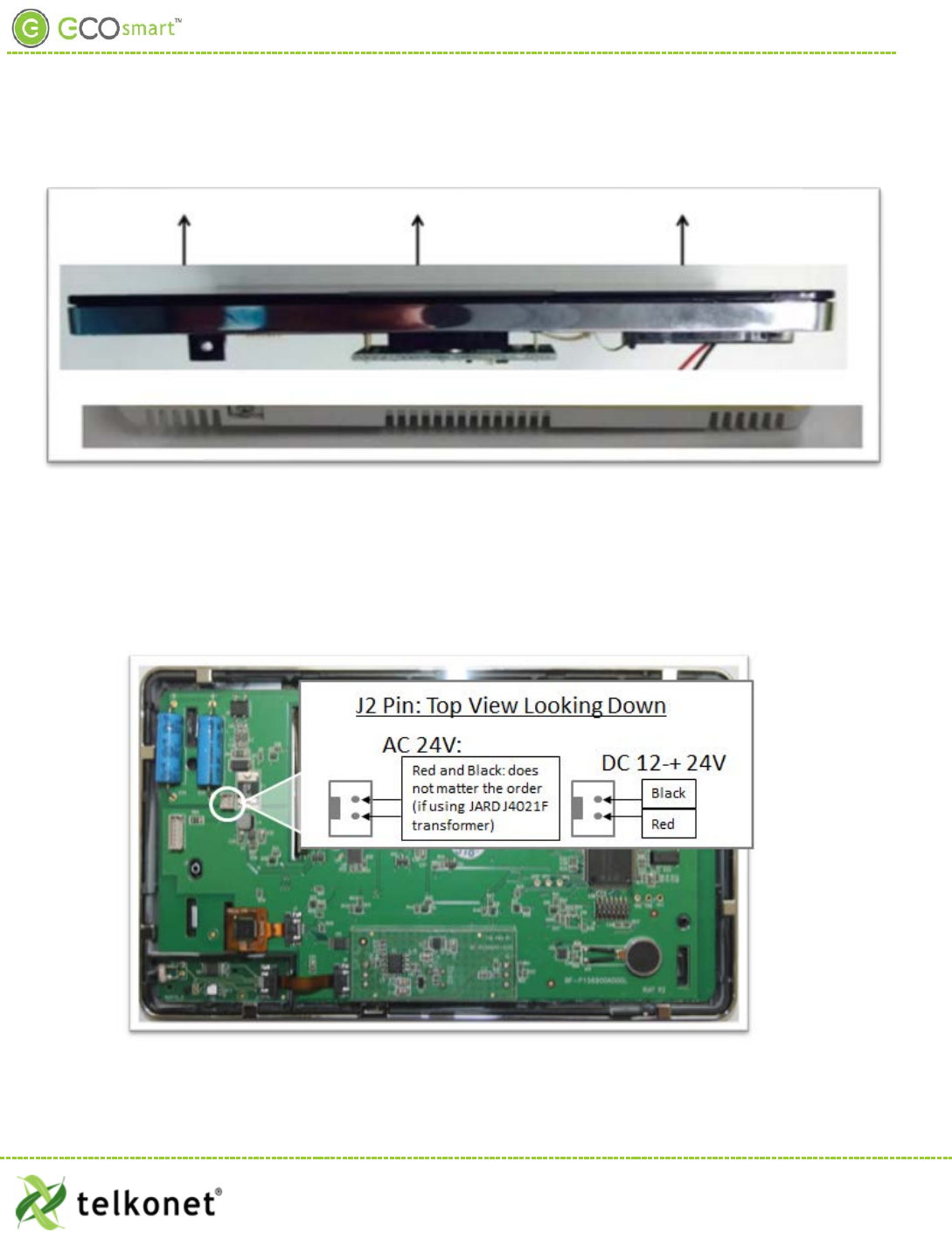
Step 8 Note the J2 pin as shown in Figure 28; this is the pin to which you will connect power.
Step 9 Note the J2 wires coming out from the wall.
Step 10 You will attach the J2 wires to the J2 pin.
Figure 28: J2 Pin
EcoWave Featuring EcoTouch IO&M Guide Telkonet, Inc.
For Use with Firmware Version 2.x 20800 Swenson Drive, Suite 175
EcoTouch Waukesha, WI 53186
Revision 2 (800) 380-9640
Page 27 www.telkonet.com
EcoTouch Installation
-If your power is an AC 24V transformer, then connect the red wire and black wire to the top 2 pins; it does
not matter whether the red wire is on top and the black wire is in the 2nd slot from the top, or
vice versa.
-If your power is a 12-24VDC installation, then connect the black wire to the top pin (this is the “Ground” or
“Common” pin) and connect red wire to the 2nd pin-the pin just below the top pin (this is the “Power” pin).
Step 11 Place the cover over the backplate, about ¼ inch to the left as shown in Figure 29.
Figure 29: Replace Cover
Step 12 Slide the cover to the right to secure it.
Step 13 Screw in the security screw.
Your EcoTouch is now installed.
EcoWave Featuring EcoTouch IO&M Guide Telkonet, Inc.
For Use with Firmware Version 2.x 20800 Swenson Drive, Suite 175
EcoTouch Waukesha, WI 53186
Revision 2 (800) 380-9640
Page 28 www.telkonet.com
EcoTouch Guest Interface
EcoTouch Guest Screen Controls & User Interface
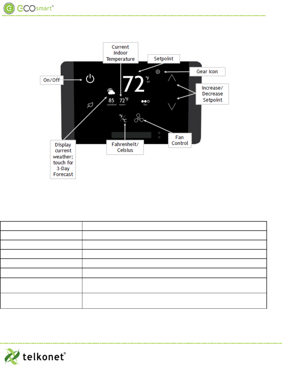
Figure 30: Guest Screen Controls
The EcoTouch front panel controls are shown below. The Administration controls can be locked out of
operation, so they are not visible until a specific unlock sequence is entered. Currently this is the 3-finger tap
as referenced on page 31.
On/Off Turn the system on and off (Optional: On/Heat/Cool/Off)
Current Indoor temperature
Display
Setpoint
Display
Gear Icon
Adjust screen brightness; language selection (see below for details)
Increase/Decrease Setpoint
Press up and down arrows to adjust setpoint within the permitted range
Fan Control Press to cycle through available fan speeds: Low, Medium, High, Auto
Fahrenheit/Celsius Toggle between Fahrenheit and Celsius temperature display (not functional
on 3-day forecast screen)
Current Weather Displays current outdoor weather; touch for 3-day forecast (see below for
details)
EcoWave Featuring EcoTouch IO&M Guide Telkonet, Inc.
For Use with Firmware Version 2.x 20800 Swenson Drive, Suite 175
EcoTouch Waukesha, WI 53186
Revision 2 (800) 380-9640
Page 29 www.telkonet.com

EcoTouch Guest Interface
Weather Forecast
• Provides a three day forecast
• Displays high and low temperature
• Displays weather graphic indicting weather conditions (sunny, cloudy, rainy, etc.)
• Displays day of the week
• Updates daily
Adjust Screen Brightness
Touch Gear icon > Touch Display Dimming > Select Dim at Night or Off at Night > Back Arrow twice to exit
Language Selection
Touch Gear icon > Select Language > Press up/down arrows to select English, Spanish, French or Portuguese >
Back Arrow twice to exit
EcoWave Featuring EcoTouch IO&M Guide Telkonet, Inc.
For Use with Firmware Version 2.x 20800 Swenson Drive, Suite 175
EcoTouch Waukesha, WI 53186
Revision 2 (800) 380-9640
Page 30 www.telkonet.com

EcoTouch Pairing
Device Association
Reminder: associating devices must be done in this order:
1. Set up EcoCommander.
2. Hard wire EcoConnect coordinators to the EcoCommander.
3. Create a network via the EcoConnect coordinator.
4. Join routers (e.g. EcoSources) to the EcoConnect coordinator.
5. Pair EcoTouch to EcoSource (see details below).
6. Pair EcoContact to EcoSource (if applicable).
7. Pair EcoSense to EcoSource (if applicable).
8. Bind routers and end devices (such as Control4, Saflok, etc.) in the room.
Pair EcoTouch with EcoSource
1. On the EcoTouch, “three-finger tap” anywhere on the screen. (“Three-finger tap” means to touch the
screen using 3 fingers, simultaneously; slightly spread out your fingers so all three fingers are
recognized by the screen.)
2. The System Status screen appears.
3. Press the Config button.
4. Enter the password C57A
5. Touch Enter.
6. Touch Pair.
7. On EcoSource, use a paperclip or pen to press the recessed button above the LED light one time (LED
will turn solid red).
8. Touch Search on EcoTouch.
9. EcoTouch will indicate “Searching for a thermostat to pair…”
10. “Success” message will appear: your EcoTouch is now paired to the EcoSource.
11. Back out of the screen by pressing Exit, then Exit, then Exit once again.
If fail, will show message, “ERROR! Failed to pair. No open EcoSource found.”
Typically the cause of the failure is that the EcoSource is not yet enabled for pairing.
Solution: Repeat the above steps, particularly Step 7.
See the Device Association Guide for detailed instructions on associating all devices.
EcoWave Featuring EcoTouch IO&M Guide Telkonet, Inc.
For Use with Firmware Version 2.x 20800 Swenson Drive, Suite 175
Waukesha, WI 53186
Revision 2 (800) 380-9640
Page 31 www.telkonet.com

EcoTouch Configuration Changes
EcoTouch Configuration Changes
Change Channel
1. On the EcoTouch, “three-finger tap” anywhere on the screen.
2. The System Status screen appears.
3. Press the Config button.
4. Enter the password C57A
5. Touch Enter.
6. Touch Reconnect
7. Touch Search
8. When “Success” message appears, press Exit, press Exit on the next screen and Exit on the third
screen.
Unpair EcoTouch
1. On the EcoTouch, “three-finger tap” anywhere on the screen.
2. The System Status screen appears.
3. Touch the Config button.
4. Enter the password C57A
5. Touch Enter.
6. Touch Unpair.
7. Touch Delete.
8. Are you sure you want to delete pairing with EcoSource? Touch Delete
9. When the “No longer Paired” message appears, touch Exit, touch Exit on the next screen and Exit on
the third screen.
Activate “Display Mode” Option
1. On the EcoTouch, “three-finger tap” anywhere on the screen.
2. The System Status screen appears.
3. Press the Config button.
4. Enter the password C57A
5. Touch Enter
6. Touch Display/Config
7. Enable Demo Mode field: touch the pencil icon to select “Y” or “N”
8. Display Style field: touch the pencil icon to select “Detailed” or “Minimal”
9. Touch Exit
FYI, touch the hamburger icon to toggle between Detailed and Minimal display modes.
System Status Screen
(Displays Firmware Version, MAC, EPID, Channel, Address, LQI and Paired status.)
1. On the EcoTouch, “three-finger tap” anywhere on the screen.
2. The System Status screen appears.
3. Touch Exit when done.
EcoWave Featuring EcoTouch IO&M Guide Telkonet, Inc.
For Use with Firmware Version 2.x 20800 Swenson Drive, Suite 175
Waukesha, WI 53186
Revision 2 (800) 380-9640
Page 32 www.telkonet.com

EcoTouch Configuration Changes
Regular Maintenance
Under normal conditions, a correctly deployed EcoSmart series will require no maintenance.
Procedure: Visual Inspection
Step 1 Verify that components have not been tampered with, destroyed or stolen.
Step 2 Verify that the components are securely mounted on their respective surfaces.
Step 3 Verify that the AC power is being supplied to the HVAC system.
Step 4 Verify that the power/data wiring between the EcoSource and the EcoTouch are intact and
connected.
Step 5 Re-associate all sensors.
Procedure: Functional Inspection
Step 1 Observe whether the HVAC system is operating (e.g. drive cycle) after entering the room.
In most cases, entering the room will have initiated an HVAC drive cycle after the Sensor detected
occupancy. Possible exceptions:
-If the temperature in the room is within hysteresis of the HVAC setpoint, a drive cycle may not
commence;
-A delay may have been programmed into the EcoSource thermostat, instructing the unit to wait for
a particular duration before triggering a drive. (Although uncommon, this feature is sometimes
requested by a property. In almost all cases, the delay is less than 3 minutes.)
Step 2 If a drive cycle does not initiate within 5 minutes of entry, force a drive cycle by temporarily
setting the thermostat to some arbitrary high or low temperature (ensure the HVAC mode is set
correctly).
EcoSource thermostats default to Occupied status if communication with the Sensor(s) is lost for any
reason. This permits the units to continue allowing the occupant to control the room temperature.
However, in this state energy savings will be lost. If in doubt whether the sensors are associated, re-
associate all Sensors.
EcoWave Featuring EcoTouch IO&M Guide Telkonet, Inc.
For Use with Firmware Version 2.x 20800 Swenson Drive, Suite 175
Waukesha, WI 53186
Revision 2 (800) 380-9640
Page 33 www.telkonet.com

Troubleshooting
Problem Potential Cause Potential Solution
HVAC unit does not operate.
Main electrical failure to the unit.
Many units operate on 230 or 277VAC
circuits, so although power is available
to the 110VAC plugs in the room, the
branch circuit supplying HVAC power
may be interrupted.
Dispatch maintenance. Verify mains
continuity to the unit.
GFI within the HVAC has tripped. Some
models of HVAC systems (often
PTAC/PTHP units) contain integral GFI
(Ground-Fault Interrupt) systems.
Occasionally, often after a power
outage, inrush current when power
returns can cause GFIs to trip. Most
times, this does not indicate issues
with the unit.
Check and reset units’ GFI systems.
EcoSource has failed.
Replace the EcoSource with a known-
good unit as a comparison-check.
If the replacement unit functions
properly, contact Telkonet and begin
the RMA process.
If the replacement unit does not
function properly, consult a local HVAC
technician to inspect your HVAC unit.
Door contact is not connected. Ensure that all door contacts are
connected.
Window or outside door is open. Ensure that no monitored windows or
patio doors are open.
EcoWave Featuring EcoTouch IO&M Guide Telkonet, Inc.
For Use with Firmware Version 2.x 20800 Swenson Drive, Suite 175
Appendix ATroubleshooting Waukesha, WI 53186
Revision 2 (800) 380-9640
Page 34 www.telkonet.com

Troubleshooting
Problem Potential Cause Potential Solution
Occupant returns to room and finds it
too hot or too cold.
During an Unoccupied period, the
EcoSmart system allows the
temperature in the room to drift away
from the occupants’ setpoint.
Telkonet’s RecoveryTime technology is
enabled to return the room to the
occupants’ setpoint within a time
defined in advance by the property
manager (this varies by property, but it
usually between 8 and 20 minutes).
Advise the occupant to wait 8 – 20
minutes. (This is the typical range of
defined recovery times requested by
customers in most installations.)
“Sensor Down” message appears on
thermostat. One or more sensors have lost
association to the thermostat.
Dispatch Maintenance to the room. Re-
associate all sensors via procedures.
Replace the batteries in all sensors
within the room.
Evaluate the wiring between each
sensor and the thermostat.
Occupant reports HVAC shuts down
while they sleep.
Sensor is not accurately detecting
occupancy. This is typically seen in
deployments where the bed placement
within the room was changed after
installation, such that the pillow area
of the bed(s) is further than 10-15 feet
from the sensor.
Assess the room, sensor placement,
and bed location(s). Verify that the
sensor(s) are deployed in accordance
with the Recommended Best Practices.
Corrective strategies may include:
a. Moving the sensor
b. Adding an additional sensor to
accommodate the new room
layout
c. Changing the room layout
d. Adjusting Sensor settings
(contact Telkonet to discuss
options)
e. Adjusting night delay (contact
Telkonet support for
assistance)
Occupant reports one mode
(heating/cooling) works but the other
does not.
Heat pump jumper is reversed or
changeover signal is backwards, or it
may be that the heat/cool jumpers are
reversed.
Correct jumper or changeover signal as
necessary.
EcoWave Featuring EcoTouch IO&M Guide Telkonet, Inc.
For Use with Firmware Version 2.x 20800 Swenson Drive, Suite 175
Appendix ATroubleshooting Waukesha, WI 53186
Revision 2 (800) 380-9640
Page 35 www.telkonet.com

Troubleshooting
Problem Potential Cause Potential Solution
Room does not achieve setpoint within
RecoveryTime.
The most common cause is that the
EcoSmart system is designed to recover
the temperature within a Comfort
Zone. The Comfort Zone is
programmable by Telkonet, and is
chosen by management before
installation.
The thermostat may be programmed
with settings not appropriate to the
specific deployment scenario.
Contact Telkonet Customer Support.
Telkonet will research the deployment
history, and determine whether a
completed Settings Sheet was provided
to us prior to thermostat shipment.
Note that Professional Services fees
may apply if a reported anomaly is
later determined to have been caused
by default settings when specific
preferences were not communicated to
Telkonet prior to device shipment.
Often an HVAC unit is in need of
servicing. For example, a unit with a
failing compressor or under-charged
refrigerant may not be able to
efficiently return the room to the
occupants’ desired setpoint.
Ensure the PTAC unit is in good working
order.
Service and correct internal thermostat
anomalies per PTAC manufacturer’s
recommended best practices.
There may be a failed control circuit
within the HVAC system
Ensure the PTAC unit is in good working
order.
Service and correct internal
thermostat
anomalies per PTAC manufacturer’s
recommended best practices.
The setpoint cannot be achieved within
the current environmental conditions.
For example, on an extremely hot or
humid day, the HVAC system may not
be able to achieve a setpoint of 60°.
Ensure the PTAC unit is in good working
order.
Service and correct internal thermostat
anomalies per PTAC manufacturer’s
recommended best practices.
EcoWave Featuring EcoTouch IO&M Guide Telkonet, Inc.
For Use with Firmware Version 2.x 20800 Swenson Drive, Suite 175
Appendix ATroubleshooting Waukesha, WI 53186
Revision 2 (800) 380-9640
Page 36 www.telkonet.com

Index
Index
Figure 1: Internal View EcoSource ............................................................................................ 5
Figure 2: Telkonet JBOX Adapter Plate ...................................................................................... 7
Figure 3: Vertical Single Gang Mud Ring ..................................................................................... 8
Figure 4: Determine Top & Bottom of Plate................................................................................. 8
Figure 5: JBOX, Mud Ring, Adapter Plate .................................................................................... 9
Figure 6: EcoSource Side View ................................................................................................ 9
Figure 7: Wiring ............................................................................................................... 10
Figure 8: Backplate on Adapter Plate ...................................................................................... 11
Figure 9: Backplate with UL-Rated Insulating Tape ...................................................................... 12
Figure 10-Line Up Hinges on Right .......................................................................................... 12
Figure 11: Metal Pins ......................................................................................................... 13
Figure 12-Speed Nut .......................................................................................................... 14
Figure 13: EcoSource Side View ............................................................................................. 15
Figure 14-Wiring............................................................................................................... 16
Figure 15: EcoSource Backplate with Appropriate Jumpers ............................................................. 16
Figure 16: Determine Top & Bottom of Plate ............................................................................. 17
Figure 17: JBOX, Mud Ring & Adapter Plate ............................................................................... 17
Figure 18: Back Plate on Adapter Plate .................................................................................... 18
Figure 19: Wiring .............................................................................................................. 18
Figure 20: EcoSource Backplate with UL-Rated Insulating Tape ........................................................ 20
Figure 21: EcoSource Backplate with Speed Nut and Drilled Hole ..................................................... 21
Figure 22-Line Up Hinges on Right .......................................................................................... 21
Figure 23: Metal Pins-Use Care.............................................................................................. 22
Figure 24: Mounting Height .................................................................................................. 24
Figure 25-Security Screw..................................................................................................... 26
Figure 26: Slide Top Left, Bottom Right ................................................................................... 26
Figure 27: Lift Up and Off ................................................................................................... 27
Figure 28: J2 Pin .............................................................................................................. 27
Figure 29: Replace Cover .................................................................................................... 28
EcoWave Featuring EcoTouch IO&M Guide Telkonet, Inc.
For Use with Firmware Version 2.x 20800 Swenson Drive, Suite 175
Appendix ATroubleshooting Waukesha, WI 53186
Revision 2 (800) 380-9640
Page 37 www.telkonet.com

Index
Figure 30: Guest Screen Controls ........................................................................................... 29
Figure 31-Before Connecting ................................................................................................ 39
Figure 32-After Connecting .................................................................................................. 39
Table 1-Wiring: ................................................................................................................ 11
Table 2: Wiring ................................................................................................................ 19
Table 3: J5 Connector Pinout ............................................................................................... 23
Table 4: EcoTouch Mounting-Best Practices............................................................................... 25
EcoWave Featuring EcoTouch IO&M Guide Telkonet, Inc.
For Use with Firmware Version 2.x 20800 Swenson Drive, Suite 175
Appendix ATroubleshooting Waukesha, WI 53186
Revision 2 (800) 380-9640
Page 38 www.telkonet.com
Appendix A
Appendix A
Proportional Valve Control
Applies only to the SS6000-VO model of thermostat
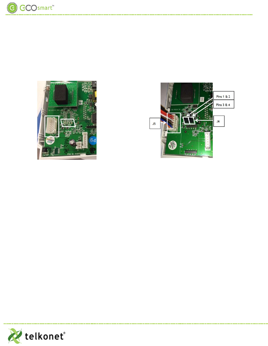
Figure 31-Before Connecting
Figure 32-After Connecting
Connecting Pins
Controlling the Cooling Valve with a 0-10 Volt Signal
1. Using the J5 Molex connector, connect Pin 5 to the Valve 0-10v input line.
2. Connect pin 1 (GND) to the Common line on the valve.
Note: You must also jumper pin 1 to the 24v COMM if the valve is referencing 24v Common.
Controlling Heating Valve with a 0-10 Volt Signal
1. Using the J5 Molex connector, connect Pin 6 to the Valve 0-10v input line.
2. Connect pin 1 (GND) to the Common line on the valve.
Note: You must also jumper pin 1 to the 24v COMM if the valve is referencing 24v Common.
Controlling an ECM Fan Motor
(Firmware must be pre-setup to provide this output.)
• Using the J5 Molex connector, connect Pin 6 to the ECM Motor 0-10v input line.
• Connect pin 1 (GND) to the Common line on the ECM Motor control board.
Note: You must also connect the 24v COMM if the valve is referencing 24v Common.
Adding Jumpers
Place 2 jumpers side-by side on connector J6. (J6 is located below the radio board. See Figure 31.
• Place one jumper on pins 1 -> 2, as shown in Figure 32. Jumper 1->2 is for 0-10V; no jumper 4-20mA.
• Place the other jumper on pins 3 -> 4. Jumper 3->4 is for 0-10V; no Jumper 4-20mA.
EcoWave Featuring EcoTouch IO&M Guide Telkonet, Inc.
For Use with Firmware Version 2.x 20800 Swenson Drive, Suite 175
Appendix ATroubleshooting Waukesha, WI 53186
Revision 2 (800) 380-9640
Page 39 www.telkonet.com

Appendix A
Calibrate the Analog Output to 5.0V
Equipment Needed: Voltmeter
• Set voltmeter to DC Voltage.
• On J5, measure between Pin 1 (Orange) and Pin 5 (White).
• Change thermostat mode to OFF.
• Enter Advanced Command 35 01 and press ON/OFF.
• Enter Advanced Command 36 36 and press ON/OFF.
• This should cause your reading to go close to 5.0V.
• Change the value of 36 36 up or down a few values so it reads close to 5.0V. If you have to raise it
more than 36 50 or lower than 36 25, then there is an issue. Contact engineering
• Enter Advanced Command 35 00
• Verify that in the OFF mode, output is approx. 0.0V.
EcoWave Featuring EcoTouch IO&M Guide Telkonet, Inc.
For Use with Firmware Version 2.x 20800 Swenson Drive, Suite 175
Appendix A Waukesha, WI 53186
Revision 2 (800) 380-9640
Page 40 www.telkonet.com