Telular 00701 Phonecell SX4E PCS Fixed Wireless Terminal User Manual 56021902
Telular Corporation Phonecell SX4E PCS Fixed Wireless Terminal 56021902
Telular >
Contents
- 1. Users Manual
- 2. amended page with 1521 statement
- 3. revised page 4
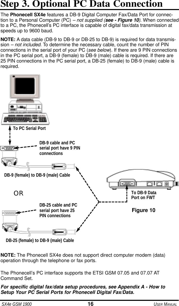
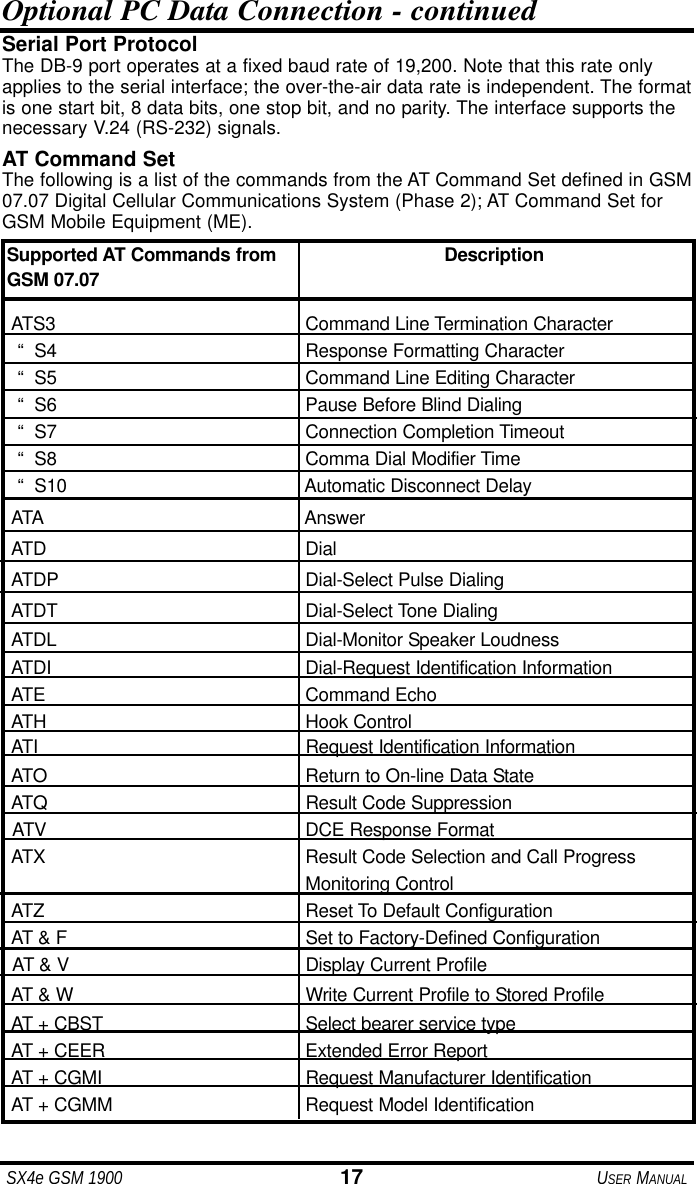
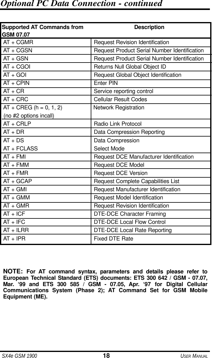
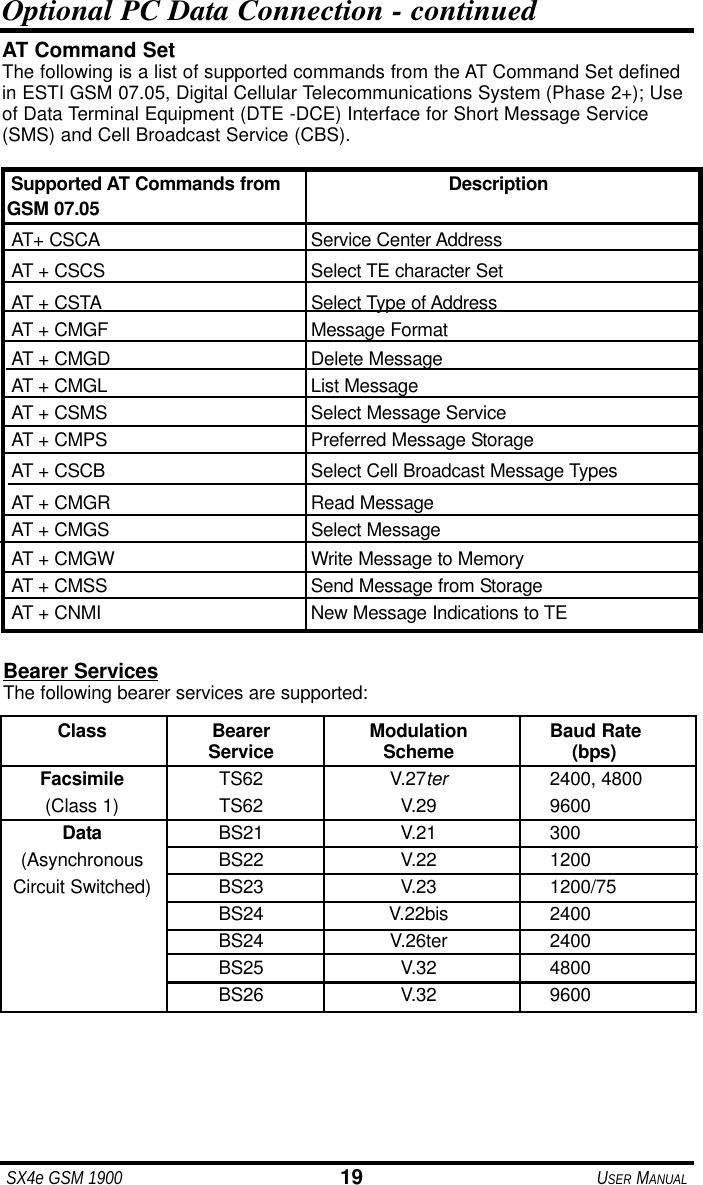
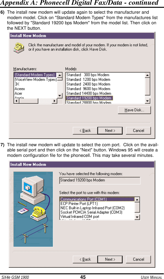
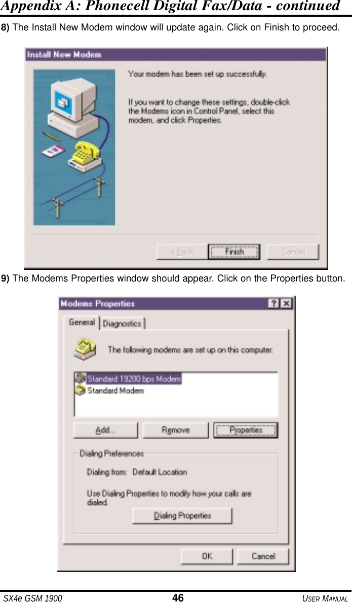
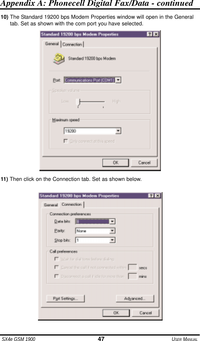
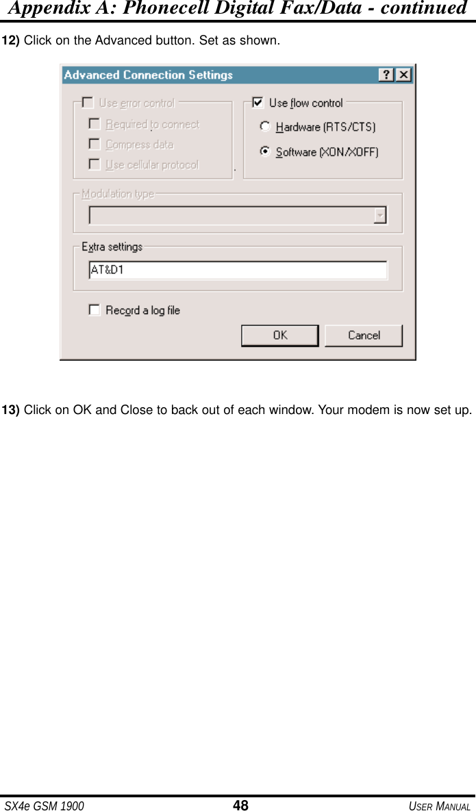
Users Manual