Telular 00701 Phonecell SX4E PCS Fixed Wireless Terminal User Manual 56021902
Telular Corporation Phonecell SX4E PCS Fixed Wireless Terminal 56021902
Telular >
Contents
- 1. Users Manual
- 2. amended page with 1521 statement
- 3. revised page 4
Users Manual
PHONECELL®SX4e GSM
1900 MHZVOICE/FAX/PC MODEL
USER MANUAL
Digital call clarity and privacy at your fingertips
07/25/01 Part No. 56021902

PHONECELL®SX4e GSM
1900 MHZVOICE/FAX/PC MODEL
USER MANUAL
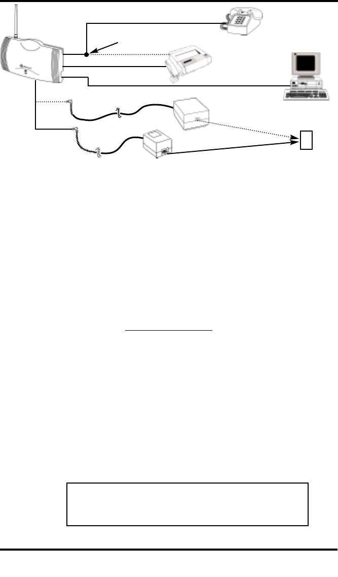
Computer
Fax
Machine
Fax Port
Serial Port
or
Thank you for choosing the Phonecell®SX4e Fixed Wireless Terminal (FWT) from
Telular. This innovative product lets you connect up to five pieces of standard telephone
equipment into a cellular network for total communications flexibility.
Please follow this guide to unpack, set up and operate your new
Phonecell SX4e FWT safely and properly.
Telular is proud to welcome you as a valued customer.
Your satisfaction is our most important concern.
Telular Corporation
Corporate Headquarters
647 North Lakeview Parkway
Vernon Hills, Illinois 60061, USA
TECHNICAL SUPPORT
Tel: 847-247-9400 · Fax: 847-247-0021
E-mail: mainoffice@telular.com · http://www.telular.com
Patents: Telular Corporation products are protected and manufactured under
one or more of the following U.S. patents and related
international patents and patents pending relating thereto:
4,658,096; 4,737,975; 4,775,997; 4,868,519; 4,922,517; 5,134,651;
5,361,297; 5,469,494; 5,046,085; 5,715,296; 5,812,637; 5,859,894;
5,946,616; 5,966,428; 6,035,220.
Trademarks: Telular Corporation owns the following registered trademarks:
TELULAR, TELULAR plus design, CELJACK, PCSone, TELCEL,
HEXAGON LOGO, PHONECELL, CELSERV, TELGUARD, and CPX.
Part No. 56021902 ©2001 Telular Corporation, all rights reserved.
PLEASE SEE PAGES 7 and 8 FOR IMPORTANT
RESTRICTIONS ON USE, AS WELL AS, WARRANTY
AND INDEMNIFICATION
Optional connection
with Single Jack
AC Power
●
●
SX4e GSM 1900 2USER MANUAL
Power
Supply
Battery Backup
Unit (optional)
Phone Port Phone(s)
Introduction

Table of Contents
Introduction.............................................................................................. 2
Technical Support.................................................................................. 2
Safety Information................................................................................... 4
Important Notices ...................................................................................... 7
Getting Started......................................................................................... 9
Unpacking Your Phonecell SX4e........................................................... 9
Pre-Installation Checklist....................................................................... 9
Installation Summary ............................................................................ 10
Step 1. Antenna Location and Setup................................................... 11
Antenna Setup..................................................................................... 11
Antenna Location Tips......................................................................... 12
Connect the Power.............................................................................. 13
Step 2. Plug in Your Telephone............................................................ 14
Connect Your Telephone ..................................................................... 14
Dual Jack Operation............................................................................ 14
Single Jack Operation ......................................................................... 14
Place a Call – Adjust Your FWT.......................................................... 15
Adding More Phones or Fax Machines............................................... 15
Step 3. Optional PC Data Connection ................................................. 16
Step 4. SIM Card Installation & Setup ................................................. 20
How to Install the Mini-SIM Card......................................................... 20
SIM PIN Programming......................................................................... 21
Step 5. Wall-Mount Installation ............................................................ 24
Phonecell SX4e Operation.................................................................... 25
How to Use the LED Status Indicators................................................ 25
How to Place a Call............................................................................. 26
How to Receive a Call......................................................................... 26
How to End a Call ............................................................................... 26
Hookflash Function.............................................................................. 26
Important Tones and Alerts.................................................................. 26
How to Use Call-Dependent Supplementary Services........................ 27
How to Adjust the Volume Level ......................................................... 28
Variable Dial Time (Auto SEND Delay) Option.................................... 28
Data After SEND (In-Call DTMF Signaling) Option............................. 28
Zero Dial Delay for Frequently Called Numbers ................................. 28
Caller ID Format.................................................................................. 29
Mobile Equipment Personalization...................................................... 30
Using Standard Supplementary Services............................................ 30
How to Make an Analog Fax Call......................................................... 34
How to Make Analog Fax Calls ........................................................... 34
How to Send Fax Calls........................................................................ 34
How to Receive Fax Calls................................................................... 34
How to Set Up Analog Fax By-Pass String......................................... 34
Dual/Single Jack Operation................................................................. 35
How to Set a Single Jack Option .........................................................35
How to Set In-Bound Fax Port Option................................................. 35
Phonecell SX4e Troubleshooting ........................................................ 36
Phonecell SX4e Programming ............................................................. 37
Phonecell SX4e User-Programming Commands................................ 37
How to Enter the User Programming Mode........................................ 37
Phonecell SX4e Technician-Programming Commands....................... 39
Appendix A: How to Setup PC Serial Ports for Phonecell
Computer Digital Fax/Data................................................................ 43
SX4e GSM 1900 3USER MANUAL
SX4e GSM 1900 4USER MANUAL
Safety Information
Your Phonecell SX4e FWT (Fixed Wireless Terminal) functions as both a radio
transmitter and receiver. When it is ON, the FWT receives and sends out radio
frequency (RF) energy. The SX4e GSM 1900 operates between 1850 MHz
and 1990 MHz. It employs the commonly used phase/frequency modulation
techniques. When you use your Phonecell SX4e, the cellular system handling
your call controls the power level at which your unit transmits. Nominal power
for the GSM 1900 unit is 1 watt.
Exposure to RF (Radio Frequency) Energy
In 1991, the Institute of Electrical and Electronics Engineers (IEEE), and in 1992, the
American National Standards Institute (ANSI), updated the 1982 ANSI Standard for
safety levels with respect to human exposure to RF energy. After reviewing the
available body of research, more than 120 scientists, engineers and physicians from
universities, government health agencies and industry developed this updated
Standard. In March, 1993, the U.S. Federal Communications Commission (FCC)
proposed the adoption of this updated Standard.
The design of your Telular Phonecell SX4e FWT (Fixed Wireless Terminal) complies
with the requirements of EN 55022, 47 CFR Part 15, Class B, and ICES-003 for con-
ducted and radiated emissions. Of course, if you want to limit RF exposure even fur-
ther than the updated ANSI Standard, you may choose to control the duration of your
calls and operate your phone in the most power-efficient manner.
Safe Operation Requirement
Do not operate your Phonecell when any person is within 1 inch (2,5 cm) of the antenna.
Protective Earth (Safety Ground) Terminal
A protective earth (safety ground) terminal (screw) marked with the
protective earth symbol is provided on the back of the SX4 Phonecell unit.
This terminal must have a permanent connection to a good earth ground
(i.e. a cold water pipe) by means of an 18 gauge or heavier insulated wire.
The wire insulation should be green with a yellow stripe to indicate that this is a
protective earth (safety ground) connection.
WARNING: The protective earth is to be installed by a qualified electrician.
Temperature Environment
Operating Temperature:: From -10°C (14°F) to +50°C (122°F);
Up to 95% relative humidity (non-condensing)
Storage Temperature: From -20°C (-4°F) to +60°C (140°F);
Up to 95% relative humidity (non-condensing)
WARNING!
Your Phonecell must be placed or mounted on a flat surface to allow proper
ventilation. Do not block the air vents or the space beneath your Phonecell as
this could cause the unit to overheat and fail.
!
IMPORTANT!
To ensure safe and efficient operation, please read the following information
and observe these guidelines whenever using your Phonecell FWT.
SX4e GSM 1900 5USER MANUAL
Safety Information - continued
Driving
Check the laws and regulations on the use of cellular products
in the areas where you drive. Some jurisdictions prohibit your
using a cellular device while driving a vehicle. Even if your
jurisdiction does not have such a law, we strongly suggest that, for safety rea-
sons, the driver use extreme caution when operating the cellular device while the
vehicle is in motion. Always obey the law.
Electronic Devices
Most modern electronic equipment is shielded from RF energy. However, RF
energy from cellular devices may affect inadequately shielded electronic
equipment.
RF energy may affect improperly installed or inadequately shielded electronic
operating and entertainment systems in motor vehicles. Check with the
manufacturer or its representative to determine if these systems are adequately
shielded from external RF energy. You should also check with the manufacturer of
any equipment that has been added to your vehicle.
Consult the manufacturer of any personal medical devices (such as pacemakers,
hearing aids, etc.) to determine if they are adequately shielded from external RF
energy.
Turn your Phonecell FWT OFF in health care facilities when any regulations
posted in the areas instruct you to do so. Hospitals or health care facilities may be
using equipment that could be sensitive to external RF energy.
Aircraft Turn OFF your Phonecell before boarding any aircraft.
•• Use it on the ground only with crew permission.
•• Do not use it in the air.
To prevent possible interference with aircraft systems, U.S. Federal Aviation
Administration (FAA) regulations require you to have permission from a crew
member to use your cellular phone (or any other cellular product) while the plane
is on the ground. To prevent interference with aircraft systems, FCC regulations
prohibit using your cellular FWT while the plane is in the air.
Children
Do not allow children to play with your Phonecell to prevent damage to the unit.
Blasting Areas
Construction crews often use remote control RF devices to set off explosives.
Therefore, to avoid interfering with blasting operations, turn your Phonecell OFF
when in a "blasting area" or in areas posted: "Turn off two-way radio."
Antenna Care and Replacement
Do not use the FWT with a damaged antenna. If a damaged antenna comes
into contact with the skin, a minor burn may result. Have your antenna replaced
by a qualified technician immediately. Use only a manufacturer-approved anten-
na. Unauthorized antennas, modifications, or attachments could damage the
FWT (Fixed Wireless Terminal) and will void the Grant of Type Acceptance.

SX4e GSM 1900 6USER MANUAL
Safety Information - continued
Potentially Explosive Atmospheres
Turn your Phonecell OFF when in any area with a potentially
explosive atmosphere. It is rare, but your Phonecell or its acces-
sories could generate sparks. Sparks in such areas could cause an
explosion or fire resulting in bodily injury or even death.
Areas with a potentially explosive atmosphere are often, but not
always, clearly marked. They include fueling areas such as gas
stations; below deck on boats; fuel or chemical transfer or storage facilities; areas
where the air contains chemicals or particles, such as grain, dust, or metal pow-
ders; and any other area where you would normally be advised to turn off your
vehicle engine.
Do not transport or store flammable gas, liquid or explosives in the area of your
Phonecell or accessories.
Vehicles using liquefied petroleum gas (such as propane or butane) must comply
with the National Fire Protection Standard (FPA-58). For a copy of this standard,
contact the National Fire Protection Association, One Batterymarch Park, Quincy,
MA 02269, Attn: Publications Sales Division.
FCC Part 15 Class B Compliance
This Phonecell SX4e model has been tested and found to comply with the limits
for a Class B digital device, pursuant to Part 15 of the FCC rules. These limits are
designed to provide reasonable protection against harmful interference in a
residential installation. This equipment generates, uses and can radiate radio
frequency energy and, if not installed and used in accordance with the
instructions, may cause harmful interference to radio communications. However,
there is no guarantee that interference will not occur in a particular installation. If
this equipment does cause harmful interference to radio or television reception,
which can be determined by turning the equipment OFF and ON, the user is
encouraged to try to correct the interference by one or more of the following
measures:
•• Reorient or relocate the antenna.
•• Increase the separation between the equipment and the terminal.
•• Connect the equipment into an outlet on a circuit different from that to which the
terminal is connected.
•• Consult your Authorized Telular Distributor or an experienced radio/TV
technician for help.
GSM Type Acceptance
The Phonecell SX4e GSM 1900 model utilizes a Telular-designed mobile terminal
integrated onto the main board. The Phonecell SX4e GSM 1900 model complies
with the TIA/EIA J-STD-007 PCS 1900 Air Interface Standard.

TERMS AND CONDITIONS FOR USE OF PHONECELL® PRODUCTS ("Product")
These Terms and Conditions are a legal contract between you and Telular Corporation for the title to and use of
the Product. BY RETAINING AND USING THE PRODUCTAFTER RECEIPT OF IT, YOU AGREE TO THE TERMS
AND CONDITIONS INCLUDING WARRANTY DISCLAIMERS, LIMITATIONS OF LIABILITYAND INDEMNIFICA-
TION PROVISIONS BELOW. IF YOU DO NOTAGREE TO THE TERMS AND CONDITIONS, DO NOT USE THE
PRODUCTAND IMMEDIATELY RETURN THE UNUSED PRODUCT FOR ACOMPLETE REFUND. You agree to
accept sole responsibility for any misuse of the Product by you; and, in addition, any negligent or illegal act or omis-
sion of your or your agents, contractors, servants, employees, or other users of the Product so long as the Product
was obtained from you, in the use and operation of the Product.
INDEMNIFICATION OF TELULAR CORPORATION ("TELULAR")
YOU SHALL INDEMNIFY, DEFEND AND HOLD HARMLESS TELULAR FOR ANY OF THE COST, INCLUDING
REASONABLE ATTORNEYS' FEES, AND FROM CLAIMS ARISING OUT OF YOU, YOUR CLIENTS' OR
OTHER THIRD PARTIES' USE OR OPERATION OF THE PRODUCT: (i) FOR MISUSE OR IN A MANNER NOT
CONTEMPLATED BY YOU AND TELULAR OR INCONSISTENT WITH THE PROVISIONS OF THIS MANUAL;
(ii) IN AN ILLEGAL MANNER OR AGAINST PUBLIC POLICY; (iii) IN A MANNER SPECIFICALLY UNAUTHO-
RIZED IN THIS MANUAL; (iv) IN A MANNER HARMFUL OR DANGEROUS TO THIRD PARTIES; (v) FROM
CLAIMS BY ANYONE RESPECTING PROBLEMS, ERRORS OR MISTAKES OF THE PRODUCT; OR (vi) COM-
BINATION OF THE PRODUCT WITH MATERIAL, MODIFICATION OF THE PRODUCT OR USE OF THE PROD-
UCT IN AN ENVIRONMENT NOT PROVIDED, OR PERMITTED, BY TELULAR IN WRITING. THE PARTIES
SHALL GIVE EACH OTHER PROMPT NOTICE OF ANY SUCH COST OR CLAIMS AND COOPERATE, EACH
WITH THE OTHER, TO EFFECTUATE THIS INDEMNIFICATION, DEFENSE AND HOLD HARMLESS.
WARRANTY
I. WHAT THIS WARRANTY COVERS AND FOR HOW LONG:
TELULAR CORPORATION ('Telular") warrants to a distributor Buyer, or to a customer only if the customer is a
Buyer directly from Telular, that the Products (including accessories) shall comply with the applicable Specifications
and shall be free from defects in material and workmanship under normal use and service for a period of fifteen
(15) months from date of shipment from Telular. Telular, at its option, shall at no charge either repair, replace or
refund the purchase price of the Product during the warranty period, provided it is returned by Buyer in accordance
with the terms of this warranty to the Telular designated repair center. Repair or replacement, at Telular's option,
may include the replacement of parts, boards or Products with functionally equivalent reconditioned items.
Repaired and replacement items are warranted for the balance of the original warranty period. All replaced items
shall become the property of Telular. SUCH ACTION ON THE PART OF TELULAR SHALL BE THE FULL
EXTENT OF TELULAR'S LIABILITY HEREUNDER, AND BUYERS EXCLUSIVE REMEDY. Buyer shall be
responsible for all costs and expenses incurred by Buyer including without limitation any handling, labor or trans-
portation charges. OTHER THAN AFORESAID, THIS EXPRESS WARRANTY IS EXTENDED BY TELULAR TO
BUYER ONLY AND NOT TO BUYER'S CUSTOMERS OR USERS OF BUYER'S PRODUCTS.
II. HOW TO OBTAIN WARRANTY SERVICE
Product covered under this warranty shall only be accepted from and returned to Buyer's designated repair cen-
ter. Buyer's dealers, distributors, agents, and end users cannot submit items to Telular under this warranty. To
receive warranty service an RMA number must first be obtained from Telular Technical Support. The defective or
non-compliant Product should be sent by Buyer freight pre-paid to: Telular Corporation, 647 North Lakeview
Parkway, Vernon Hills, IL60061, USA or other designated location. The product must be packaged in the original
carton and packing material or an equivalent package and must have the assigned RMA number clearly marked
on the carton. Returned Product received without an RMA number will be returned to the sender.
III. WARRANTY CONDITIONS:
This is the complete warranty for the Products manufactured by Telular and sold to Buyer. Telular assumes no
obligation or liability for additions or modifications to this warranty unless made in writing and signed by an officer
of Telular. Unless made in separate written agreement between Telular and Buyer, Telular does not warrant the
installation, field maintenance or service of the Products or parts.
Important Notices
SX4e GSM 1900 7USER MANUAL

TELULAR CANNOT BE RESPONSIBLE IN ANY WAY FOR ANY ANCILLARY EQUIPMENT NOT FURNISHED
BY TELULAR WHICH IS ATTACHED TO OR USED IN CONNECTION WITH THE PRODUCTS OR FOR OPER-
ATION OF THE PRODUCTS WITH ANY ANCILLARY EQUIPMENT AND ALL SUCH EQUIPMENT IS
EXPRESSLY EXCLUDED FROM THIS WARRANTY. FURTHERMORE, TELULAR CANNOT BE RESPONSI-
BLE FOR ANY DAMAGE TO THE PRODUCTS RESULTING FROM THE USE OF ANCILLARY EQUIPMENT
NOT FURNISHED BY TELULAR FOR USE WITH THE PRODUCTS.
WHEN THE PRODUCT IS USED IN CONJUNCTION WITH ANCILLARY OR PERIPHERAL EQUIPMENT NOT
MANUFACTURED BY TELULAR, TELULAR DOES NOT WARRANT THE OPERATION OF THE
PRODUCT/PERIPHERAL COMBINATION, AND TELULAR SHALL HONOR NO WARRANTY CLAIM WHERE
THE PRODUCT IS USED IN SUCH A COMBINATION AND IT IS DETERMINED BY TELULAR THAT THERE IS
NO FAULT WITH THE PRODUCT. TELULAR DISCLAIMS LIABILITY FOR RANGE, COVERAGE, AVAILABIL-
ITY, OR OPERATION OF THE CELLULAR SYSTEM WHICH IS PROVIDED BY THE CARRIER.
IV. WHAT THIS WARRANTY DOES NOT COVER:
(a) Subsequent upgrades and enhancements to the Product. (b) Defects, non-compliance or damage resulting
from use of the Product in other than its normal and customary manner or environment. (c) Defects, noncompli-
ance or damage from misuse, lightening, accident or neglect. (d) Defects, noncompliance or damage from improp-
er testing, operation, maintenance, installation, adjustment, or any alteration or modification of any kind. (e)
Product disassembled or repaired in such a manner as to adversely affect performance or prevent adequate
inspection and testing to verify any warranty claim. (f) Product which has had the serial number removed or made
illegible. (g) Defects, non-compliance or damage due to spills of food or liquid. (h) All plastic surfaces and all other
externally exposed parts that are scratched or damaged due to customer normal use. (i) Costs and expenses,
including without limitation handling, labor and transportation, incurred in returning Product for warranty service to
Telular's Repair Center. (j) Repair, programming or servicing by someone other than Telular.
V. GENERAL PROVISIONS:
THIS WARRANTY IS GIVEN IN LIEU OF ALL OTHER EXPRESS OR STATUTORY WARRANTIES. IMPLIED
WARRANTIES, INCLUDING WITHOUT LIMITATION IMPLIED WARRANTIES OF MERCHANTABILITY, FIT-
NESS FOR A PARTICULAR PURPOSE, TITLE, INFRINGEMENT, DELIVERY, NEGLIGENCE AND PERSON-
AL INJURY, ARE DISCLAIMED. FURTHER, AS THE CELLULAR CARRIER IS NOT CONTROLLED BY TELU-
LAR, NO WARRANTY IS MADE AS TO COVERAGE, AVAILABILITY OR GRADE OF SERVICE PROVIDED BY
THE CELLULAR CARRIER. IN NO EVENT SHALL TELULAR BE LIABLE FOR DAMAGES IN EXCESS OF THE
PURCHASE PRICE OF THE PRODUCT, FOR ANY LOSS OF USE, LOSS OF TIME, INCONVENIENCE, COM-
MERCIAL LOSS, LOST PROFITS OR SAVINGS OR OTHER INCIDENTAL, SPECIAL OR CONSEQUENTIAL
DAMAGES ARISING OUT OF THE USE OR INABILITY TO USE SUCH PRODUCT TO THE FULL EXTENT
SUCH MAY BE DISCLAIMED BY LAW. SOME JURISDICTIONS DO NOT ALLOW THE EXCLUSION OR LIM-
ITATIONS OF INCIDENTAL OR CONSEQUENTIAL DAMAGES OR LIMITATION ON HOW LONG AN IMPLIED
WARRANTY LASTS.
VI. SOFTWARE PROVISIONS:
Laws in the United States and other countries preserve for Telular certain exclusive rights for copyrighted Telular
software such as the exclusive rights to reproduce in copies and distribute copies of such Telular software. Telular
software may be copied into, used in and redistributed with only the Product associated with such Telular software.
No other use, including without limitation, disassembly of such Telular software or exercise of exclusive rights in
such Telular software is permitted and Telular reserves all rights not expressly granted in this Limited Commercial
Warranty.
Important Notices - continued
SX4e GSM 1900 8USER MANUAL
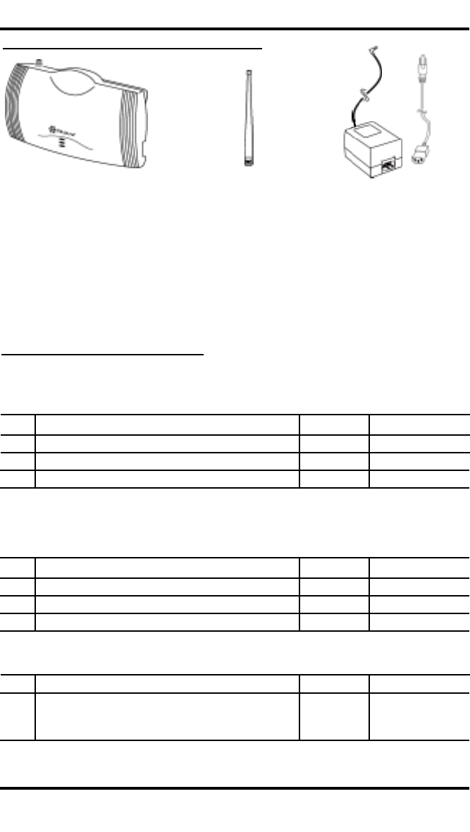
The Phonecell SX4e comes with the following:
➊Phonecell SX4e Fixed Wireless Terminal (FWT)
➋Dipole antenna
➌3-Wire, Linear Power Supply with 6 kV Lightning and Surge Protection, and
AC Line Cord
Carefully remove the unit from the shipping carton and check for evidence of
shipping damage. If damage is found, contact your Authorized Telular
Distributor or shipping agent immediately.
Getting Started...
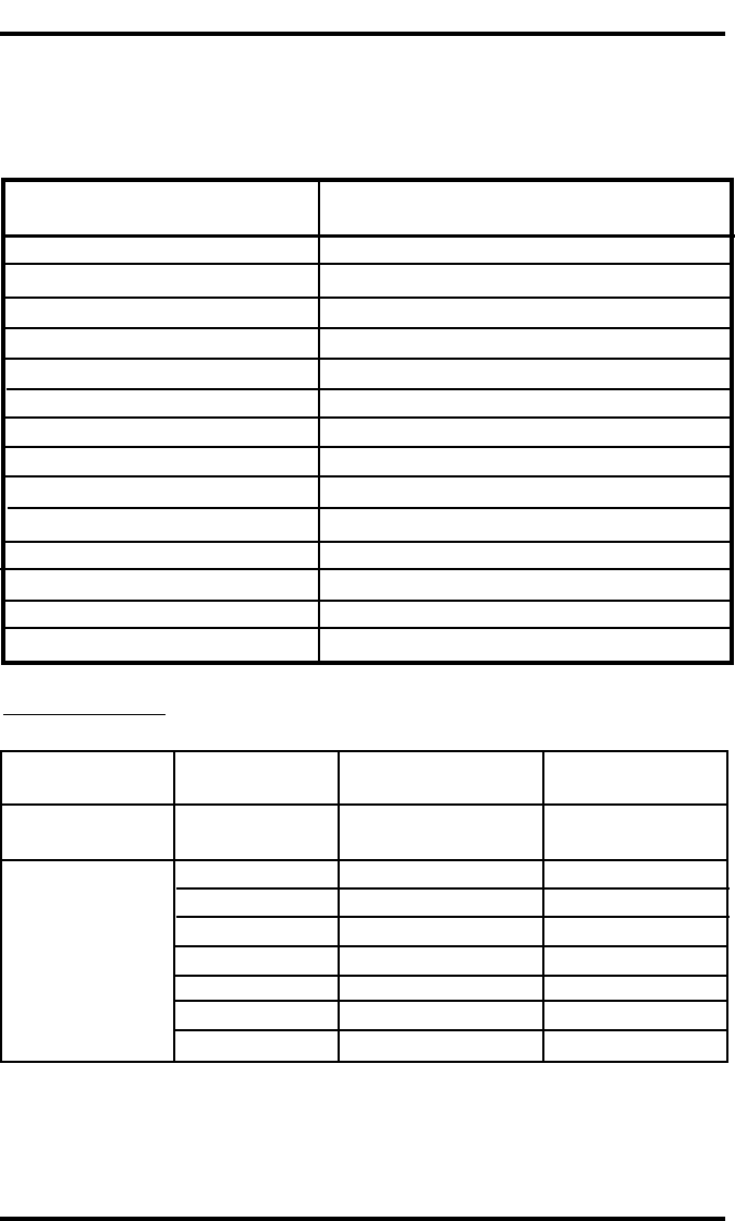
Pre-Installation Checklist
Before attempting Phonecell SX4e installation, make sure you have the following
components, tools and materials.
Qty. Description Supplied Not Supplied
1 Mini-SIM (Subscriber ID Module) Card* ✔
1 RJ-11 Modular Phone Cord ✔
1
Data Cable - for Digital Fax/Data Transmission**
✔
* Supplied by your Network Service Provider
** See “Step 3: Optional PC Data Connection” section of this manual.
Additional Components Needed
Qty. Description Supplied Not Supplied
Phone Line Splitter –if you plan to connect ✔
more than one telephone to the FWT
Optional Components
Tools & Materials Needed – for Wall-Mount Installation Only
Qty. Description Supplied Not Supplied
1 Drill & Drill Bit ✔
1 Screwdriver ✔
21
1/2-inch (3.75 cm) Mounting Screws ✔
➊➌
➋
Unpacking Your Phonecell SX4e
SX4e GSM 1900 9USER MANUAL
Installation Summary
There are five steps to installing the Phonecell SX4e FWT properly. These steps
are summarized below and explained in detail in the remainder of this manual.
Step 1. Choose an Antenna Location (pages 11 - 13)
••Choose an antenna location.
••Connect the antenna.
••Connect the FWT to a good earth ground.
••Connect power to the FWT. Allow time for the unit to find service
and stabilize.
••Then, check the cellular signal strength and move the antenna
until you achieve the best signal possible.
Step 2. Plug In Your Telephone (pages 14 - 15)
••Once the antenna is connected, hook up a phone.
••Then, make a test call to verify proper operation.
Adjust the antenna location accordingly.
NOTE:If your Phonecell SX4e did not come
with a pre-installed mini-SIM (Subscriber Identity
Module) card, you need to perform the SIM Card
Installation and Setup procedure in Step 4. Then,
return to this step (2).
••Choose Single or Dual jack option (Dual jack allows
you to connect a separate fax line)- see the
Connect Your Telephone section of this manual.
••You may plug in additional phones via a Line Splitter
(not supplied) if desired.
Step 3. Optional PC Data Connection (pages 16 - 19)
••Now that the Phonecell is functioning properly,
plug in your computer for computer digital
fax/data transmission, using a DB-9 cable
(not supplied).
Step 4. SIM Card Installation & Setup (pages 20 - 23)
••If your Phonecell did not come with a pre-
installed mini-SIM card, you need to perform the
SIM Card Installation and SIM PIN Setup.
••Otherwise, continue to Step 5.
Step 5. Wall-Mount Installation (pages 24)
••After you’ve selected a location and made all the
necessary connections and adjustments, your
Phonecell SX4e is ready for wall-mounting.
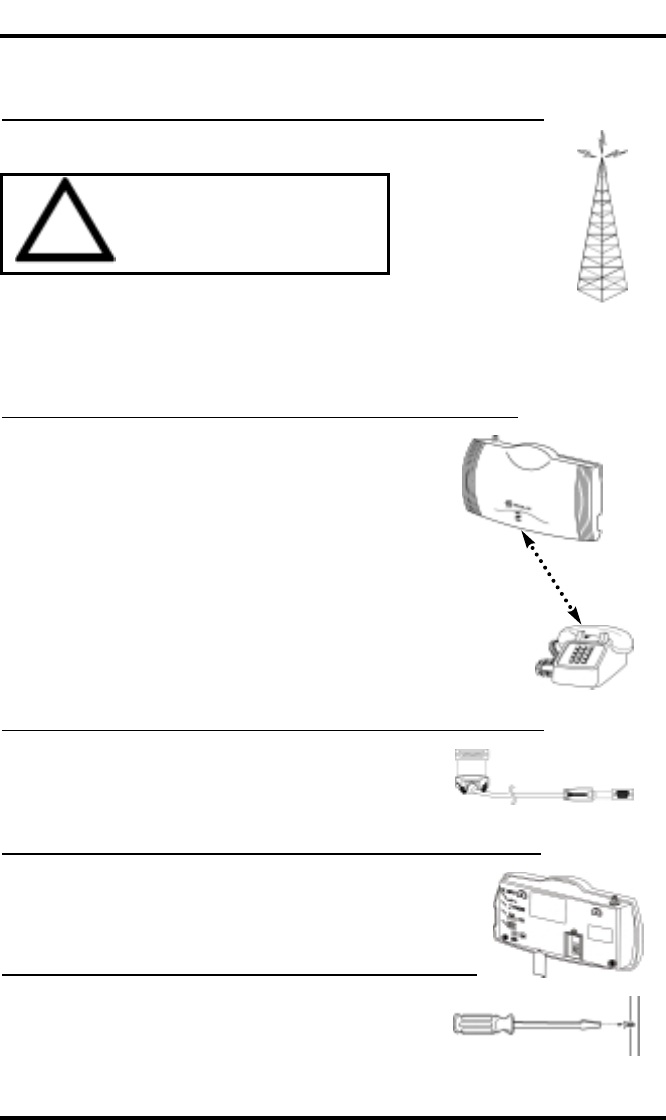
WARNING!
DO NOT power unit antenna is
connected, as it may burn out the
radio transmitter.
!
SX4e GSM 1900 10 USER MANUAL
SX4e GSM 1900 11 USER MANUAL
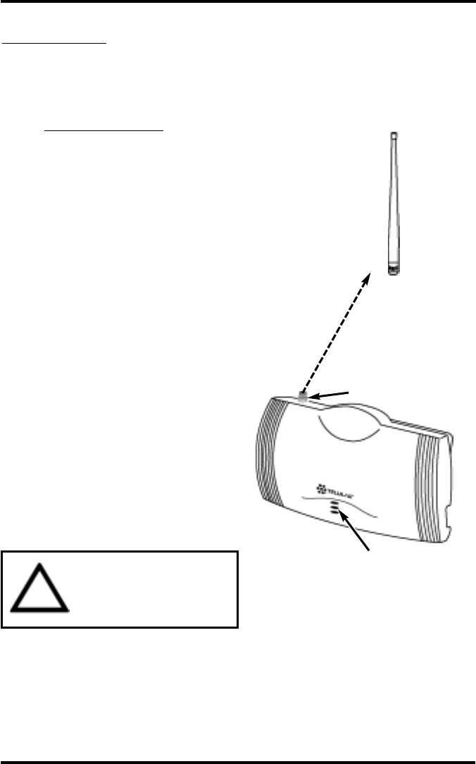
Step 1. Antenna Location and Setup
The Phonecell SX4e comes with a dipole antenna.
Antenna Setup:
1) Connect the antenna to the TNC
antenna connector on top of the
FWT - see Figure 1.
2) Connect power to the FWT - see
the Connect the Power section
of this manual. Wait for the unit to
acquire service.
3) Check the LED cellular status
indicator (middle LED) on
the front of your Phonecell:
•• RED Continuous = No Service
••RED Flashing = SIM Problem
••GREEN Continuous = Good signal.
••GREEN Flashing = Poor signal.
4) Move the antenna from one
location to another until you
achieve the best signal
strength possible (GREEN).
5) When you’re getting a strong
(GREEN) signal, you’re ready for
the next step - connecting a phone
and making a call.
NOTE: If you’re still receiving a
Continuous RED “no-service”
signal, contact your service
provider to make sure cellular
service is activated.
If the LED is flashing RED, there’s
a SIM card problem - see Step 5.
WARNING!
Never operate your Phonecell
when any person is within 1
inch (2,5 cm) of the antenna.
!
Female TNC
Antenna
Connector
Standard
Dipole
Antenna
Figure 1 LED Cellular
Status Indicator
Antenna Location & Setup - continued
SX4e GSM 1900 12 USER MANUAL
Your Phonecell receives operating commands from the cellular network
and relies upon signal strength for proper operation. Therefore, finding an
antenna location with good signal strength is critical for optimal call clarity.
After you choose a good location, connect the antenna, test the signal
strength and adjust the location accordingly.
A
NTENNA
L
OCATION
T
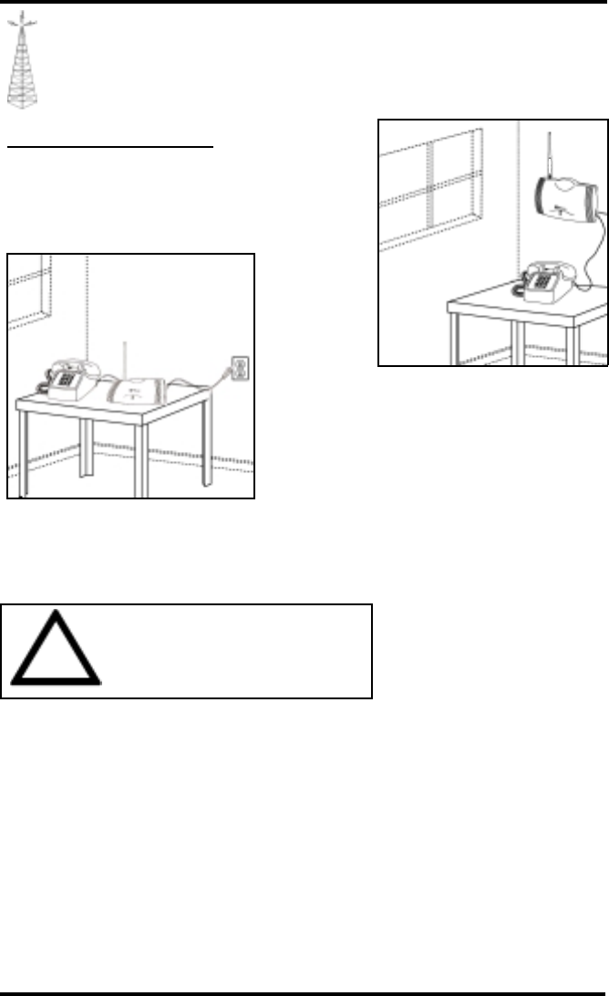
IPS
••Locate the antenna above ground and as close
to windows (or exterior walls) as possible - see
Figure 2 and Figure 3.
WARNING!
DO NOT install antenna close to
telephones, as the RF emissions will
cause interference.
!
Figure 2– Wall-mount with
antenna pointed upward and located
near a window for optimum signal
strength.
Figure 3– Table-mount with antenna
pointed upward and located near a
window for optimum signal strength.
SX4e GSM 1900 13 USER MANUAL
LED
Power
Indicator
Figure 6
Protective earth (safety
ground) terminal screw
Figure 4
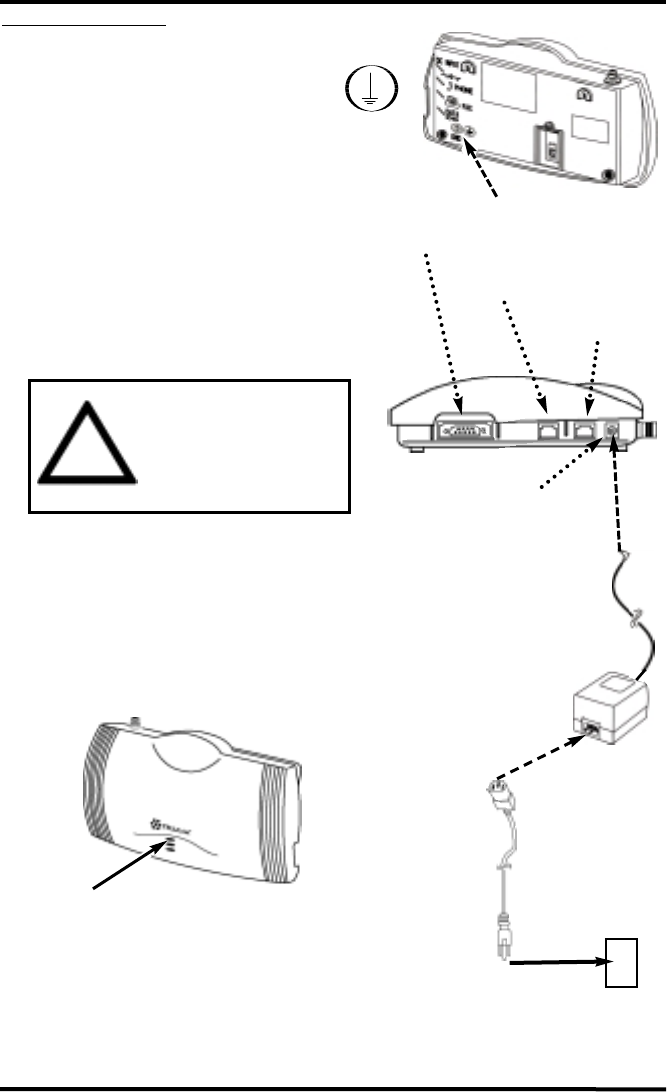
Connect the Power
1) A protective earth (safety ground) terminal
(screw) marked with this protective earth
symbol is provided on the back of the
SX4e Phonecell unit - see Figure 4.
2) Connect this terminal to a good earth ground
(i.e. a cold water pipe) by means of an 18
gauge or heavier insulated wire. The wire
insulation should be green with a yellow stripe
to indicate that this is a protective earth (safe-
ty ground) connection.
WARNING: The protective earth is to be
installed by a qualified electrician.
3) Connect the Line Cord from the AC power
source to the Power Supply.
4) Connect the barrel plug on the Power Supply
to the Power Input port on the side of the
Phonecell.
5) The LED Power Status indicator (located on
the front of the FWT) will turn green immedi-
ately upon connecting to power - see Figure 6.
WARNING!
The mounting bracket and
protective earth/ground wire
must be installed on the
Phonecell before power is
applied.
!
Figure 5
Antenna Location & Setup - continued
Fax Port
Serial Port
Phone Port
Power Input Port
AC Power
Line Cord
●
●
Power
Supply
Step 2. Plug In Your Telephone
SX4e GSM 1900 14 USER MANUAL
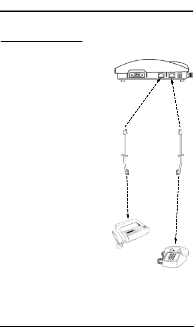
Phone Cord
To Fax Port
To Phone Port
Figure 7: Dual Port
To Fax Machine
To Phone(s)
Phone Cord
The Phonecell SX4e lets you connect up to a 5 REN telephone load into a
cellular network. Follow the steps below for quick installation.
Connect Your Telephone
Dual-Jack Operation
The Phonecell SX4e may be operated in either
dual-jack or single-jack mode. The factory default
is the dual- jack mode. In dual-jack operation, for
outgoing calls, the first jack to seize the line (go
off-hook) will disconnect the other jack. The other
jack will remain disconnected until the first jack
goes back on-hook. For incoming calls, voice
calls will be routed to the Phone voice jack and
fax calls will be routed to the Fax jack. See How
to Set A Single Jack Option, to change program-
ming to single jack operation.
1) Locate the modular line port on your
phone and plug in one end of a standard
phone cord.
2) Connect the other end of the cord to the
telephone port (marked PHONE) on the side
of your Phonecell SX4e - see Figure 7.
NOTE: An RJ-11 connector will fit into the
Phone port.
NOTE: The Phonecell SX4e does not
support direct computer modem (data)
operation through the Phone port or Fax
port. It also does not support the phone
through the fax port.
3) Locate the modular line port on
your fax machine and plug in one end of a
standard phone cord.
4) Connect the other end of the cord
to the fax port (To the Left of the Phone
port) on the side of your Phonecell SX4e.
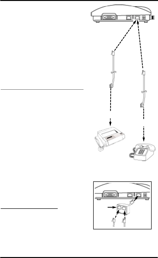
Single-Jack Operation
The analog fax jack can be disabled leaving
only the telephone jack operational (single-jack
operation). In single-jack operation, voice calls
can be placed and received normally if a tele-
phone is connected. If a fax is connected,
incoming analog fax calls can be received
normally, but to place outbound fax calls using
the voice jack, a bypass sequence must be
used as a prefix in the dialed telephone number.
SX4e GSM 1900 15 USER MANUAL
Line
Splitter Phone
Port
Phone
Cords
Figure 9 – An optional Line Splitter
lets you connect additional phones
to your Phonecell SX4e.
Phone Cord
To Phone Port
Figure 8: Single Port
Phone Cord
To Fax Machine
To Phone(s)
OR
1) Locate the modular line port on your fax
machine or phone and plug in one end of
a standard phone cord.
2) Connect the other end of the cord to the
phone port (marked PHONE) on the side
of your Phonecell SX4e - see Figure 8.
NOTE: An RJ-11 connector will fit into the
Phone port.
NOTE: To place outbound fax calls using the
voice jack, see the How to Set up an Analog
Fax Bypass String section of this manual. For
single jack programming, see the How to Set
A Single Jack Option section of this manual.
Place a Call - Adjust Your FWT
1) Pick up the phone receiver and listen for
dial tone.
2) If you hear dial tone, make a call.
3) While you’re talking with the other party,
listen for buzz and echo. If you hear either,
move the antenna and/or POTS phone
until you find the location where voice
conversation is strong, and buzz and echo
are minimized.
NOTE: If you are unsuccessful in
dialing out, verify the following:
••The antenna location needs to be
adjusted - see Figure 2.
••The SIM card needs to be installed and/or
set up - see Step 4.
••Your cellular phone number has not been
activated - contact your cellular
service provider.
Adding More Phones
Plug in a line splitter (not supplied) to connect
additional phones to your FWT- see Figure 9.
NOTE: The FWT will only let you make one
phone call at a time.
PBX/KSU Systems - NOTE: PABX
installation should only be performed by
experienced telephone technicians.
Plug In Your Telephone - continued
The Phonecell’s PC interface supports the ETSI GSM 07.05 and 07.07 AT
Command Set.
For specific digital fax/data setup procedures, see Appendix A - How to
Setup Your PC Serial Ports for Phonecell Digital Fax/Data.
SX4e GSM 1900 16 USER MANUAL
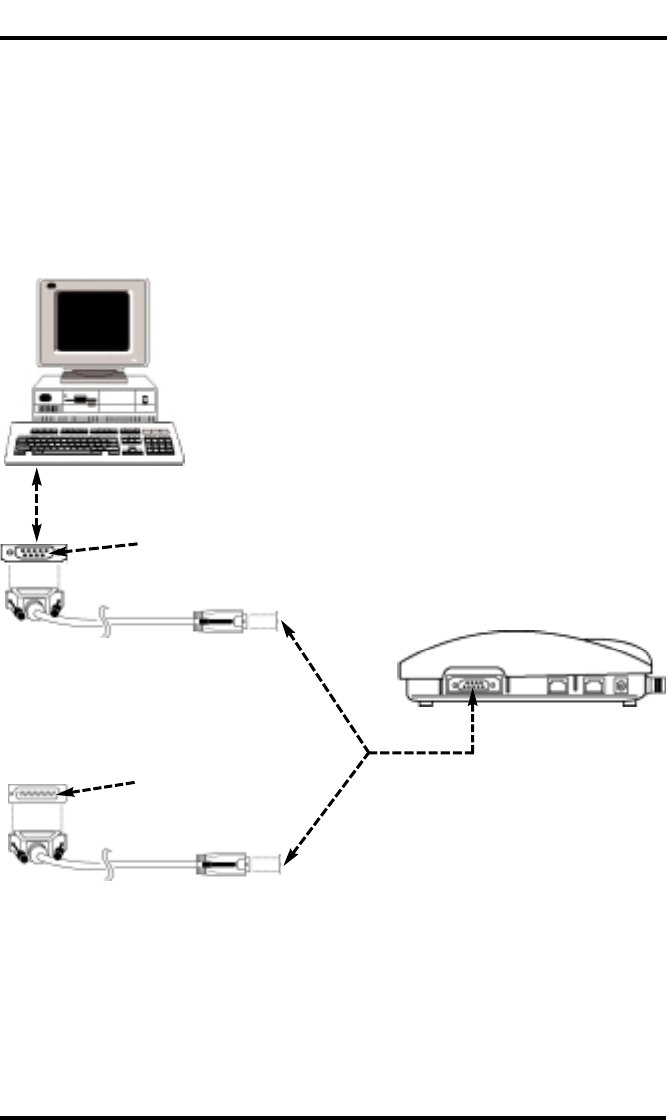
Step 3. Optional PC Data Connection
The Phonecell SX4e features a DB-9 Digital Computer Fax/Data Port for connec-
tion to a Personal Computer (PC) – not supplied (see - Figure 10). When connected
to a PC, the Phonecell’s PC interface is capable of digital fax/data transmission at
speeds up to 9600 baud.
NOTE: A data cable (DB-9 to DB-9 or DB-25 to DB-9) is required for data transmis-
sion – not included. To determine the necessary cable, count the number of PIN
connections in the serial port of your PC (see below). If there are 9 PIN connections
in the PC serial port, a DB-9 (female) to DB-9 (male) cable is required. If there are
25 PIN connections in the PC serial port, a DB-25 (female) to DB-9 (male) cable is
required.
To PC Serial Port
To DB-9 Data
Port on FWT
DB-25 (female) to DB-9 (male) Cable
DB-25 cable and PC
serial port have 25
PIN connections
DB-9 (female) to DB-9 (male) Cable
DB-9 cable and PC
serial port have 9 PIN
connections
OR
Figure 10
NOTE: The Phonecell SX4e does not support direct computer modem (data)
operation through the telephone or fax ports.

SX4e GSM 1900 17 USER MANUAL
Optional PC Data Connection - continued
Serial Port Protocol
The DB-9 port operates at a fixed baud rate of 19,200. Note that this rate only
applies to the serial interface; the over-the-air data rate is independent. The format
is one start bit, 8 data bits, one stop bit, and no parity. The interface supports the
necessary V.24 (RS-232) signals.
AT Command Set
The following is a list of the commands from the AT Command Set defined in GSM
07.07 Digital Cellular Communications System (Phase 2); AT Command Set for
GSM Mobile Equipment (ME).
Supported AT Commands from Description
GSM 07.07
ATS3 Command Line Termination Character
“ S4 Response Formatting Character
“ S5 Command Line Editing Character
“ S6 Pause Before Blind Dialing
“ S7 Connection Completion Timeout
“ S8 Comma Dial Modifier Time
“ S10 Automatic Disconnect Delay
ATA Answer
ATD Dial
ATDP Dial-Select Pulse Dialing
ATDT Dial-Select Tone Dialing
ATDL Dial-Monitor Speaker Loudness
ATDI Dial-Request Identification Information
ATE Command Echo
ATH Hook Control
ATI Request Identification Information
ATO Return to On-line Data State
ATQ Result Code Suppression
ATV DCE Response Format
ATX Result Code Selection and Call Progress
Monitoring Control
ATZ Reset To Default Configuration
AT & F Set to Factory-Defined Configuration
AT & V Display Current Profile
AT & W Write Current Profile to Stored Profile
AT + CBST Select bearer service type
AT + CEER Extended Error Report
AT + CGMI Request Manufacturer Identification
AT + CGMM Request Model Identification

Optional PC Data Connection - continued
SX4e GSM 1900 18 USER MANUAL
Supported AT Commands from Description
GSM 07.07
AT + CGMR Request Revision Identification
AT + CGSN Request Product Serial Number Identification
AT + GSN Request Product Serial Number Identification
AT + CGOI Returns Null Global Object ID
AT + GOI Request Global Object Identification
AT + CPIN Enter PIN
AT + CR Service reporting control
AT + CRC Cellular Result Codes
AT + CREG (h = 0, 1, 2) Network Registration
(no #2 options incall)
AT + CRLP Radio Link Protocol
AT + DR Data Compression Reporting
AT + DS Data Compression
AT + FCLASS Select Mode
AT + FMI Request DCE Manufacturer Identification
AT + FMM Request DCE Model
AT + FMR Request DCE Version
AT + GCAP Request Complete Capabilities List
AT + GMI Request Manufacturer Identification
AT + GMM Request Model Identification
AT + GMR Request Revision Identification
AT + ICF DTE-DCE Character Framing
AT + IFC DTE-DCE Local Flow Control
AT + ILRR DTE-DCE Local Rate Reporting
AT + IPR Fixed DTE Rate
NOTE: For AT command syntax, parameters and details please refer to
European Technical Standard (ETS) documents: ETS 300 642 / GSM - 07.07,
Mar. ‘99 and ETS 300 585 / GSM - 07.05, Apr. ‘97 for Digital Cellular
Communications System (Phase 2); AT Command Set for GSM Mobile
Equipment (ME).
SX4e GSM 1900 19 USER MANUAL
Class Bearer Modulation Baud Rate
Service Scheme (bps)
Facsimile TS62 V.27ter 2400, 4800
(Class 1) TS62 V.29 9600
Data BS21 V.21 300
(Asynchronous BS22 V.22 1200
Circuit Switched) BS23 V.23 1200/75
BS24 V.22bis 2400
BS24 V.26ter 2400
BS25 V.32 4800
BS26 V.32 9600
Bearer Services
The following bearer services are supported:
AT Command Set
The following is a list of supported commands from the AT Command Set defined
in ESTI GSM 07.05, Digital Cellular Telecommunications System (Phase 2+); Use
of Data Terminal Equipment (DTE -DCE) Interface for Short Message Service
(SMS) and Cell Broadcast Service (CBS).
Supported AT Commands from Description
GSM 07.05
AT+ CSCA Service Center Address
AT + CSCS Select TE character Set
AT + CSTA Select Type of Address
AT + CMGF Message Format
AT + CMGD Delete Message
AT + CMGL List Message
AT + CSMS Select Message Service
AT + CMPS Preferred Message Storage
AT + CSCB Select Cell Broadcast Message Types
AT + CMGR Read Message
AT + CMGS Select Message
AT + CMGW Write Message to Memory
AT + CMSS Send Message from Storage
AT + CNMI New Message Indications to TE
Optional PC Data Connection - continued
SX4e GSM 1900 20 USER MANUAL
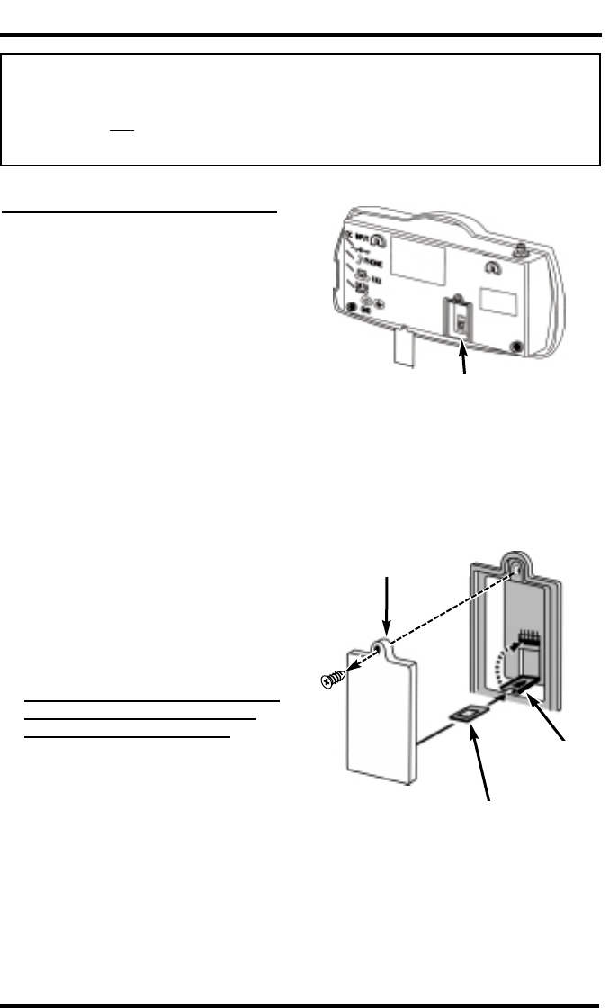
Step 4. SIM Card Installation & Setup
How to Install the Mini-SIM Card
The GSM module within the Phonecell
requires a Subscriber Identification
Module (SIM) for normal operation. The
service provider supplies a SIM card,
which carries the account information
needed to operate the Phonecell. The
mini-SIM compartment is on the back of
the Phonecell - see Figure 11.
NOTE: If your mini-SIM card is already
installed, skip to the SIM PIN
Programming section of this manual.
If you don’t have a mini-SIM card,
contact your network service provider.
1) Disconnect DC power.
2) Remove the SIM compartment cover
by removing the screw.
3) Open the SIM card holder.
4) Line up the mini-SIM card with the
arrow on the SIM card holder.
5) Gently insert the mini-SIM card in the
slot of the SIM card holder - See
Figure 12.
6) Close the SIM card holder.
NOTE: If you insert the SIM card
improperly, the holder will not
close. Do not force it shut. Make
sure the SIM card is aligned properly
with the directional arrow on the hold-
er.
7) Reattach the SIM compartment cover
with the screw.
8) Reconnect DC power.
9) Proceed with SIM PIN Programming.
IMPORTANT!
If your Phonecell did NOT come with a pre-installed mini-SIM (Subscriber Identity
Module) card, OR if you’re experiencing SIM card-related problems, follow the
steps below. Otherwise, continue with STEP 5.
Figure 11
Figure 12 - Mini-SIM Card Installation
Mini-SIM Card
SIM Compartment
Cover
Mini-SIM
Card Holder
Mini-SIM
Compartment

SX4e GSM 1900 21 USER MANUAL
SIM PIN Programming
The mini-SIM may require entry of a Personal Identification Number (PIN). The PIN
is a four- to eight-digit number provided with the SIM card. If the service provider has
set the SIM to require PIN entry, the Phonecell will request the PIN each time it is
powered ON or the SIM is removed and replaced. The PIN can be stored within the
Phonecell for automatic entry when required. To use the automatic PIN entry feature,
the PIN must be correctly programmed and automatic PIN entry must be enabled.
If PIN entry is requested while automatic PIN entry is disabled, the Phonecell emits
a SIM Inactive tone. The SIM PIN can be manually entered at that time by dialing
the PIN and pressing #. If entry is successful, the SIM Inactive tone will be replaced
by service dial tone.
How to Enable/Disable the Automatic PIN Entry Feature
1) Using a POTS (Plain Old Telephone Set) phone connected to the telephone port,
lift up the handset (take off-hook).
NOTE: You must have tone-dial (DTMF) capability to enable/disable the
Automatic PIN Entry Feature.
2) Enter the Programming mode:
Press: #*0*1 2 3 4 5 6 7 8 #
The dial tone will cease upon entry of the first digit. If you enter the access code
correctly, the dial tone should change to a different, steady Programming tone
and the bottom LED indicator on the front of the Phonecell will blink alternately
RED and GREEN to indicate that you’re in the programming mode.
3). Once in Programming mode:
Press: # *65 *< auto_PIN> *<PIN> #
• To disable automatic PIN entry, set the "auto PIN" value to 0.
• To enable automatic PIN entry, set the "auto PIN" value to 1.
You must enter either 0or 1, otherwise, the FWT will not update or store this
value and the existing stored parameter will remain. The factory default value is
0 (disabled). The factory default PIN setting within the FWT’s non-volatile
memory is "1234."
4) Correct entry will be confirmed by the return of the programming tone, which
signifies that the unit is ready to accept the next entry. Incorrect entry will result in
a short, three tone sequence of rising frequencies, followed by the return of the
programming tone, which again signifies that the unit is ready to accept the
corrected entry.
5) Hang up the telephone handset (place on-hook).
For Example: To enable automatic PIN entry for PIN "1234,"
dial: # *65 *1 *1234 #
IMPORTANT!
Automatic PIN entry must be disabled before the SIM is changed (including
initial entry) so that the PIN for the new SIM card can be entered correctly
before the GSM module requests the PIN.
Continued...

SX4e GSM 1900 22 USER MANUAL
SIM PIN Programming - continued
How to Change the PIN Value Entered by the Automatic PIN Entry Feature
REMINDER: Automatic PIN entry must be disabled - before and while the automatic
PIN entry value is changed - until programming of the new PIN and Auto PIN Entry
completed.
1) Using a tone-dial (DTMF) POTS telephone connected to the Phone port, lift up
the handset(take off-hook).
2) Enter the Programming mode:
Press: #*0*1 2 3 4 5 6 7 8 #
The dial tone will cease upon entry of the first digit. If you enter the access code
correctly, the dial tone should change to a different, steady “Programming” tone
and the bottom LED indicator on the front of the Phonecell will blink alternately
RED and GREEN to indicate that you’re in the programming mode.
3) Press: # *64 *< old_PIN> *<new PIN> *<new PIN> #
The new SIM PIN will be supplied by the service provider with a new SIM.
If the SIM card is changed, the PIN must be reprogrammed using the above
command with the correct new PIN for the new SIM.
NOTE: The factory default PIN setting within the FWT’s non-volatile memory is
"1234."
4) Correct entry will be confirmed by the return of the programming tone, which
signifies that the unit is ready to accept the next entry. Incorrect entry will result in
a short, three tone sequence of rising frequencies, followed by the return of the
programming tone, which again signifies that the unit is ready to accept the
corrected entry.
5) Hang up the telephone handset (place on-hook).
For Example: To set up a new SIM with PIN "5678,"
dial: # *64 *1 2 3 4 *5 6 7 8 *5 6 7 8 #
NOTE: This procedure will not change the PIN encoded on the SIM. It will only
change the PIN stored in the FWT for automatic entry of the PIN when requested
by the GSM module.
If the SIM card in use has SIM PIN Entry enabled, it is strongly recommended
that Automatic PIN Entry be selected.
IMPORTANT!
You must enter the PIN correctly. After three attempts to load an incorrect PIN, the
SIM will be blocked and the SIM card will have to be unblocked. If you do not
have the unblocking key, the SIM will have to be returned to the service provider
for reactivation. See How to Unblock a SIM PIN to unblock a SIM card.

SIM PIN Programming - continued
SX4e GSM 1900 23 USER MANUAL
How to Set a New PIN in the SIM
REMINDER: Automatic PIN entry must be disabled - before and while the SIM PIN
is changed - until programming of the new PIN and Auto PIN Entry (see previous
page) is completed.
1) Using a tone-dial (DTMF) POTS telephone connected to the Phone port, lift up
the handset (take off-hook).
2) Press: **04 *< old_PIN> *<new_PIN> *<new_PIN> #
NOTE: You must know the old PIN to change it and the new PIN must be 4 to 8
digits (0 −9) in length.
3) Incorrect entry of the old PIN will be indicated by a short, three tone sequence of
rising frequencies. Hang up the telephone handset and start over at step 1 with the
correct old PIN.
Incorrect length (less than 4 or more than 8 digits) of the new PIN or not entering
the same value in both new PIN entries will result in silence. Hang up the tele-
phone handset and start over at step1.
Correct entry will be confirmed by a short beep. Hang up the telephone handset.
For Example: To set up a new SIM with PIN "5678," where the old PIN is
“1234,” dial: ** 04 *1 2 3 4 *5 6 7 8 *5 6 7 8 #
NOTE: In case of PIN2, substitute the following step 2:
2) Press: **042 *<old_PIN2> *<new_PIN2> *<new_PIN2> #
NOTE: You must know the old PIN2 to change it and the new PIN2 must be 4 to
8 digits (0 −9) in length.
For Example: To set up a new SIM with PIN2 "5678," where the old PIN2 is
“1234,” dial: ** 042 *1 2 3 4 *5 6 7 8 *5 6 7 8 #
NOTE: This procedure will change the PIN encoded on the SIM. It will not
change the PIN stored in the FWT for automatic entry of the PIN when request-
ed by the GSM module. (See previous page for instructions on how to enter the
auto-entry PIN value).
How to Unblock a SIM PIN
Use the following key sequence to unblock a SIM card:
1) Press: ** 05 *<PIN_unblocking key> *<new_PIN *<new PIN> #
2) Press: **052 *<PIN2_unblocking key> *<new_PIN2 *<new PIN2> #
NOTE: This procedure will change the PIN encoded on the SIM. It will not
change the PIN stored in the FWT for automatic entry of the PIN when request-
ed by the GSM module. (See previous page for instructions on how to enter the
auto-entry PIN value).
SX4e GSM 1900 24 USER MANUAL
Step 5. Wall-Mount Installation
After you’ve selected a location and made all the necessary connections,
your Phonecell SX4e is ready for wall-mounting.
PRE-INSTALLATION TIPS:
•Make sure the location is dry, away from
overhead water pipes, and protected
from weather conditions.
•The area should be free of airborne
contaminants.
•The Phonecell SX4e power supply
should be located within 2 meters (6
feet) of an AC power outlet.
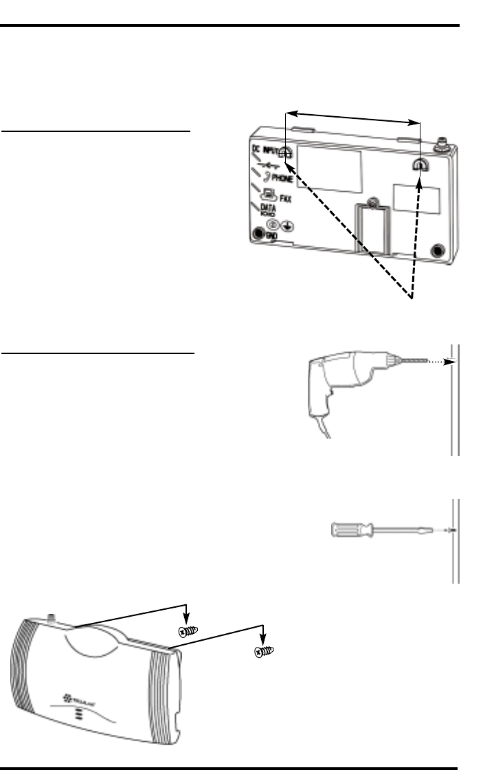
Wall-Mount Instructions:
1) To mount the FWT on a wall, mark
two hole locations 166 mm (6-17/32
inch) apart. These hole locations
match the mounting hooks on the
back of unit -see Figure 13.
2) Install the screws (not supplied), leav-
ing a gap (approximately 3mm (1/8
inches)) between screw head and wall
- see Figures 14 and 15.
3) Mount the FWT onto the screws - see
Figure 16.
Figure 16
Figure 14
Figure 15
Mounting Hooks
166 mm (6-17/32 inches)
Figure 13
SX4e GSM 1900 25 USER MANUAL
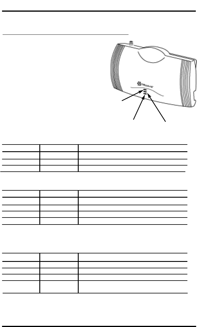
Phonecell SX4e Operation
1) Plug in the power supply.
2) Wait approximately 10 seconds for
the unit to initialize.
3) The three LED indicators on the
front of your Phonecell will turn ON.
The Tables below describe the
modes and operation of the three
indicators - see Figure 17.
Once your Phonecell SX4e is installed and tested, it’s ready for operation.
How to Use the LED Status Indicators
LED 1 – Power Status
LED 3 – FWT Status
LED 1 – Power Status Indicator
LED Color LED Activity Description
GREEN Continuous FWT Power ON
YELLOW Continuous Low-Voltage Detection
NONE (Dark) None No FWT Power
LED 2 – Cellular Status Indicator
LED Color LED Activity Description
GREEN Continuous Good Cellular Signal Strength
GREEN Flashing Poor Cellular Signal Strength
RED Continuous No cellular service*
RED Flashing SIM Card Problem
LED 3 – FWT Status Indicator
LED Color LED Activity Description
GREEN Continuous Normal Operation
GREEN/RED Alternating Programming Mode
RED Continuous FWT Failure**
RED Flashing Phone or Fax Interface Failure, Check
external wiring to telephone
LED 2 – Cellular
Status
*Contact your service provider to verify that cellular service is activated.
**Contact your Authorized Telular Service Representative
Figure 17

SX4e GSM 1900 26 USER MANUAL
Phonecell Operation - continued
How to Place a Call
1) Pick up your telephone handset (your phone is now “off-hook”).
2) Listen for dial tone (If service is not available, a No-Service tone is
produced. Hang-up the phone and try again. If the No-Service tone continues,
contact your service provider to make sure cellular service is activated.).
3) Dial the phone number.
How to Receive a Call
••When your telephone rings, pick up the handset and begin talking.
How to End a Call
••Hang-up the phone (place the handset back onto the telephone cradle).
The Hookflash Function
When you initiate the Hookflash function, it automatically lets you:
••Speed up the connection after you dial a phone number.
••Answer an incoming call that occurs when you’re dialing a phone number.
••Use special (supplementary) cellular services which may be available in your
cellular service area (see the Using Standard Supplementary Services section
of this manual).
How to Use the Hookflash Function
Depending upon your phone, there are two ways to initiate the Hookflash function:
••Press the dedicated “HOOKFLASH” or “FLASH” key on your telephone.
••Press the hang-up or switch-hook mechanism on your phone once quickly
(approximately 1/2-second).
Important Tones and Alerts
No-Service Tone – When cellular service is not available, the receiver emits a
No-Service (fast-beeping) tone instead of the normal (steady) dial tone.
ROH (Receiver Off-Hook) Tone – If the telephone equipment remains off-hook
(off its cradle) with no dialing activity for 45 seconds, the receiver emits an ROH
tone for 60 seconds.
Incoming Call Alert – If you’re dialing a number and an incoming call occurs,
the receiver will emit an audible ring. To answer the incoming call:
••Press the “HOOKFLASH” button once. This will connect the incoming call.
••OR hang-up immediately. This will cause the phone to start ringing.
Supplementary Service Dial Tone – When supplementary services are
enabled and active, the receiver may emit a special dial tone to indicate that
one or more services are active.
Roam Dial Tone – When cellular service is available, but the Phonecell is in a
Roam area, the receiver may emit a different dial tone to indicate the roaming
condition. However, unless the FWT is re-programmed in the field, the factory
default tone is set the same as normal service dial tone.
Non-Registered Service Tone – When the SIM Card is inactive, missing from
the Phonecell, or installed but requires PIN entry, the receiver emits a
non-registered service tone instead of the normal (steady) dial tone.

SX4e GSM 1900 27 USER MANUAL
Phonecell Operation - continued
How to Use Call-Dependent Supplementary Services
Call-dependent supplementary services are those services handled within an
active call. These features are network-dependent. Check with your cellular
provider to determine available features.
Use the following commands to activate the call-dependent supplementary services:
NOTE: <send> is provided by the hookflash function (See the Hookflash
Function section of this manual).
To Release All Held Calls or Set User Determined User Busy For a Waiting Call:
Press: 0 <send>.
To Release All Active Calls and Accept the Held/Waiting Call:
Press: 1 <send>.
To Release a Specific Active Call x:
Press: 1 x <send> (xrepresents the call ID 1-7).
To Place All Active Calls on Hold and Accept the Held/Waiting Call:
Press: 2 <send>.
To Place All Active Calls on Hold Except Call x:
Press: 2 x <send> (xrepresents the call ID 1-7).
To Add a Held Call to the Conversation:
Press: 3 <send>.
To Place All Active Calls on Hold and Make the Call to the Specified Phone
Number:
Press: PhoneNo <send>.
NOTE: When both a held and a waiting call exist in a conflicting situation, the
above procedures apply to the waiting call.
Call Waiting:
Permits a subscriber to be notified of an incoming call while the subscriber is
engaged in an active or held call. The subscriber can either accept, reject, or
ignore the incoming call.
Activate: *43 #
Deactivate: # 43 #
Interrogate: *# 43 #
Call Hold:
Allows a served subscriber, who is provisioned with this supplementary service, to
interrupt communication on an existing active call and then subsequently, if
desired, re-establish communication. The traffic channel remains assigned to the
subscriber after the communication is interrupted to allow origination or possible
termination of other calls.

Phonecell Operation - continued
How to Adjust the Volume Level
If the volume level on your phone is too high or too low, you can adjust the levels
using the keypad on your telephone. Note: your telephone must be in Tone-
Dial (DTMF) mode to adjust the levels.
To Increase Audio Level - Increase the audio level in steps by pressing:
# *8(also known as #*Up)
Continue to press #*8until the desired level is reached.
To Decrease Audio Level - Decrease the audio level in steps by pressing:
# *3(also known as #*Down)
Continue to press #*3until the desired level is reached.
NOTE: The default setting lets you adjust the audio up to three (3) steps from
the default volume in either direction (Up or Down). The volume setting
remains in effect for future calls until changed manually, even if the telephone
is on-hooked. If the Phonecell power is cycled (turned OFF/ON), the default
mid-range volume setting will be restored.
Variable Dial Time (Auto SEND Delay) Option
When you place a call, your Phonecell SX4e automatically sends the phone
number over the cellular network after you dial the last digit – just like a landline
phone. However, to make sure you have enough time to dial the last digit, a 3-sec-
ond Auto SEND Delay is programmed into the unit at the factory. To change the
Auto SEND Delay setting, see the How To Set the Auto SEND Delay section of this
manual.
Data After SEND (In-Call DTMF Signaling) Option
Depending upon your cellular provider, the Data After SEND option may need to be
Enabled or Disabled to use special cellular features such as call waiting, three-way
conference calls, voice mail, etc. Please consult your service provider for the
required Data After Send/In-Call DTMF Signaling configuration.
The factory default setting is 0 (In-Band Signaling only). To change the Data After
SEND setting, see the How To Set Data After SEND (In-Call DTMF Signaling) sec-
tion of this manual.
Zero Dial Delay for Frequently Called Numbers
A new patented feature enables the Phonecell to recognize your frequently called
phone numbers and send them immediately–without the 3-second Auto SEND
Delay. The Phonecell stores a list of up to 50 numbers in its memory. This list con-
tains any number that you’ve called at least twice successfully.
NOTE: Cycling (turning OFF/ON) the power will erase the current list. A new list will
be started when power is re-applied. To enable or disable this feature,
see the
Enable/Disable Zero Dial Delay for Frequently Called Numbers
section of this manual.
SX4e GSM 1900 28 USER MANUAL

SX4e GSM 1900 29 USER MANUAL
Phonecell Operation - continued
Caller ID Format
The Phonecell SX4e GSM 1900 FWT will support Caller ID device operation. The
FWT factory default format is designed to work for most Caller ID devices. If the
Caller ID device does not respond, then change the FWT Caller ID format using
the programming command below. The Phonecell can be programmed with an
ordinary touch-tone telephone.
NOTE: The User Programming mode is not accessible during a call. Refer to
the Phonecell SX4e Programming section of this manual to enter the
Programming Mode.
Enter Caller ID Format
The following key sequence is used to select the Caller ID format:
Press # *84 *<CID format> #
The Caller ID Format factory default value will work for most Caller ID devices. If
the Caller ID device does not respond, program a value of 1in the "CID Format"
field. If the Caller ID device still does not respond, then program a value of 2. If
the value is not in the range 0 to 2, it is considered invalid and the FWT will not
update or store this value; the currently stored value will remain. The factory
default value is 0.
When the FWT is programmed to Format 0, date and time information is not pro-
vided by the FWT. When the FWT is programmed to Format 1 or Format 2, the
FWT provides "January 1, Midnight" as generic time and date information. The
actual display of this generic date and time ("January 1, Midnight") will vary as it
is determined by the Caller ID device.
For Caller ID Devices with Date and Time Display
When the Caller ID device is first powered, the date and time information will
begin from "January 1, Midnight." The user cannot change the date and time
through the FWT.
When the Caller ID format is set to factory default 0, date and time will continue
to advance. Each incoming call will not affect the date and time.
When the Caller ID format is set to either 1 or 2, the date and time will be reset to
"January 1, Midnight" for each incoming call.

SX4e GSM 1900 30 USER MANUAL
Mobile Equipment Personalization
The terminal will support all five lock type features of GSM 02.02 Personalization
features check information stored in the terminal which limits the SIMs with which
the terminal will operate.Factory default is all lock types set to be deactivated.
Please contact Telular Corporation if you need more information on this feature.
Using Standard Supplementary Services
Your Phonecell SX4e is compatible with a variety of special services, including:
••Call Forwarding
••Call Barring
••Call Waiting
••Three-Way Calling
••Caller ID
••Voice Mail
and more...
Depending upon your cellular provider, these services may be available on a
subscription basis. However, certain dialing sequences must be entered. Please
consult your service provider for the dialing instructions for your system.
Standard supplementary services are defined as those supplementary services
handled while not in a call. Depending on the supplementary service, several
commands may be available. The command list is defined below:
Registration - The programming by the user of information to enable subsequent
operation of a service. This action involves input of specific supplementary infor-
mation. For example, when call-forwarding registration is initiated by the user, a
forwarding number must be supplied.
Erasure - The deletion of information stored against a particular service by a pre-
vious registration.
Activation - An action taken by the FWT user to enable a previously registered
process to run.
Deactivation - An action taken by the FWT user to terminate the process started
at activation.
Depending on the supplementary service, additional parameters may be required
to successfully complete an operation, such as phone number or password. Some
supplementary services have optional parameters, such as Teleservice and/or
Delay settings. Delay is the amount of time to wait before completing performance
of a service that has a condition controlling its activity; for example, call forward
on no answer waits an amount of time equal to the "delay" for the phone to be
answered before declaring no answer and forwarding the call.
Teleservice:10 = All Teleservices, 11 = Speech, 12 = Data, 13 = Fax, 16 = SMS,
19 = All Teleservices except SMS.
Delay: 5-30 seconds
PhoneNo: Up to 20 digits (0-9)
NOTE: <send> is provided by the hookflash function (See the Hookflash
Function section of this manual).
Phonecell Operation - continued

SX4e GSM 1900 31 USER MANUAL
Call Forwarding Unconditional:
Allows a called subscriber to have the network send immediately all incoming calls, or just
those associated with a specific teleservice, addressed to the called subscriber's directory
number to another directory number.
Register: ** 21 *Ph No *Teleservice # <Send>
or
*21 *Ph No *Teleservice # <Send>
Erase: # # 21 *Teleservice # <Send>
Activate: *21 * Teleservice # <Send>
Deactivate: # 21 *Teleservice # <Send>
Call Forwarding on Mobile Subscriber Busy:
Allows a called subscriber to have the network send immediately all incoming calls, or just
those associated with a specific basic service group, addressed to the called subscriber's
directory number and which meet "subscriber busy" to another directory number.
Register: ** 67 *Ph No *Teleservice # <Send>
or
*67 *Ph No *Teleservice # <Send>
Erase: # # 67 *Teleservice # <Send>
Activate: *67 *Teleservice # <Send>
Deactivate: # 67 *Teleservice # <Send>
Call Forwarding on No Reply:
Allows a called subscriber to have the network send all incoming calls, or just those associated
with a specific basic service group, addressed to the called subscriber's directory number and
which meet "no reply" for a specific amount of time to another directory number.
Register: ** 61 *Ph No *Teleservice *Delay # <Send>
Erase: # # 61 *Teleservice # <Send>
Activate: *61 *Teleservice # <Send>
Deactivate: # 61 *Teleservice # <Send>
Call Forwarding on Mobile Subscriber Not Reachable:
Allows a called subscriber to have the network send all incoming calls, or just
those associated with a specific Teleservice group, addressed to the called mobile
subscriber's directory number, but which is determined to be "not reachable", to
another directory number.
Register: ** 62 *Ph No *Teleservice # <Send>
Erase: # # 62 *Teleservice # <Send>
Activate: *62 *Teleservice # <Send>
Deactivate: # 62 *Teleservice # <Send>
Call Forwarding All Call Forwarding:
Allows a called subscriber to have the network send-after the stated delay-all
incoming calls, or just those associated with a specific teleservice, addressed to
the called subscriber's directory number to another directory number.
Register: ** 002 *Ph No *Teleservice *Delay #
<Send>
Erase: # # 002 *Teleservice # <Send>
Activate:*002 *Teleservice # <Send>
Deactivate: # 002 *Teleservice # <Send>
Phonecell Operation - continued

SX4e GSM 1900 32 USER MANUAL
Call Forwarding Conditional Call Forwarding:
Register: ** 004 *Ph No *Teleservice *Delay #
<Send>
Erase: # # 004 *Teleservice # <Send>
Activate: *004 *Teleservice # <Send>
Deactivate: # 004 *Teleservice # <Send>
Calling Line Identification Restriction:
If subscribed to in temporary mode, enable the calling party to countermand the
subscribed-to presentation of its line identity to the called party for a specific call
(i.e., the next call) only. (If subscribed to in permanent mode, the network will pre-
vent presentation of the calling party’s line identity to the calling party for every
outgoing call.)
If subscribed to in temporary mode with default value “presentation restricted,”
the user may suppress CLIR, for the specific call only:
Register: *31 # Call Phone Number <Send>
If subscribed to in temporary mode with default value “presentation not
restricted,” the user may invoke CLIR, for the specific call only:
Register: # 31 # Call Phone Number <Send>
Barring of All Outgoing Calls:
Allows a subscriber to have barring of certain categories of outgoing calls accord-
ing to a barring program which is selected from a set of one or more barring pro-
grams chosen at provision time and is valid for all outgoing calls, or just those
associated with a specific Teleservice.
Activate: *33 *Password *TeleService # <Send>
Deactivate: # 33 *Password *TeleService # <Send>
Barring of Outgoing International Calls:
Outgoing call setup possibilities exist only to subscribers of the PLMN(s) and the
fixed network(s) of the country where the mobile subscriber is presently located.
Activate: * 331 *Password *TeleService # <Send>
Deactivate: # 331 *Password *TeleService # <Send>
Barring of Outgoing International Calls Except Those Directed to the Home
PLMN Country:
Outgoing call setup possibilities exist only to subscribers of the PLMN(s) and the
fixed network(s) of the country where the subscriber is presently located or to sub-
scribers of the home PLMN country of the served subscriber and to subscribers of
the fixed network(s) in the home PLMN country.
Activate: *332 *Password *TeleService # <Send>
Deactivate: # 332 *Password *TeleService # <Send>
Phonecell Operation - continued

SX4e GSM 1900 33 USER MANUAL
Barring of All Incoming Calls:
Allows a subscriber to have barring of certain categories of incoming calls accord-
ing to a barring program which is selected from a set of one or more barring pro-
grams chosen at provision time and is valid for all incoming calls, or just those
associated with a specific basic service group.
Activate:*35 *Password *TeleService # <Send>
Deactivate: # 35 *Password *TeleService # <Send>
Barring of Incoming Calls when Roaming Outside the Home PLMN Country:
Calls which are terminated for the served subscriber is barred if the subscriber is
roaming outside the home PLMN country.
Activate: *351 *Password *TeleService # <Send>
Deactivate: # 351 *Password *TeleService # <Send>
All Call Barring:
On activation all calls is barred; on deactivation all call barring is disabled.
Activate: *330 *Password *TeleService # <Send>
Deactivate: # 330 *Password *TeleService # <Send>
All Outgoing Call Barring:
On activation all outgoing calls is barred; on deactivation all outgoing call barring
is disabled.
Activate: *333 *Password *TeleService # <Send>
Deactivate: # 333 *Password *TeleService # <Send>
All Incoming Call Barring:
On activation all incoming calls is barred; on deactivation all incoming call barring
is disabled.
Activate: *353 *Password *TeleService # <Send>
Deactivate: # 353 *Password *TeleService # <Send>
Enter Caller ID Format Selection:
The following key sequence is used to enter the Caller ID format selection.
# *84 *<CID format> #
The CID format value is set to 0to select a CID Multiple Data Message Format
(MDMF) with no date of time information; set to 1to select a CID MDMF with date
and time information fixed at midnight, January 1; set 2to select a CID Single
Data Message Format (SDMF) with the date and time information at midnight,
January 1. If the CID format is greater than 2, it is considered invalid. The factory
default is 0.
Unstructured Supplementary Services:
Allows a user and a PLMN operator-defined application to communicate in a way
which is transparent to the terminal and to intermediate network entities.
"any characters, from GSM 3.08 default alphabet" # <Send>
or
"1 or 2 characters, from GSM 3.08 default alphabet" <Send>
Phonecell Operation - continued

SX4e GSM 1900 34 USER MANUAL
How to Make an Analog Fax Call
How To Make Analog Fax Calls
Analog (i.e. normal fax from fax machine) fax calls (CCITT Group 3, Bearer
Service TS 62) can be made from phone and fax jacks, depending on the option
set.
How to Send Fax Calls
Step by Step Fax Instructions
1. Set up your fax machine just as you would for a wired telephone.
2. Outgoing fax calls at the fax jack are processed directly. Outgoing fax
calls at the phone jack always require the analog fax bypass string,
since the default for this jack is voice calls. See the User Programming
Commands section of this manual for analog fax setup.
NOTE: Make sure the fax machine is properly connected as shown in Figure 7.
How to Receive Fax Calls
By factory default, you do not have to do anything to receive a fax, provided you
have set-up your fax machine as shown in Figure 7. However, the user can have
options to receive a fax through the phone port. Refer to the User Programming
section of this addendum for instructions on programming of the single jack option
and in-bound fax port option.
How to Set Up Analog Fax Bypass String
NOTE: The analog fax bypass string can only be used in single jack operation.
This feature allows the phone jack to process the next outgoing call as an analog
fax call. After this call, the phone jack automatically returns to the default voice
protocol. The user enters this string prior to dialing the telephone number. The ter-
minal interprets the string and properly sets up the call. Refer to the following
examples.
To Send a Fax on a Fax Machine Connected to the Phone Jack:
1. Lift up the handset (take off-hook).
2. Dial # *19 *1 #, followed by the fax number to be called.
3. Press START on the fax machine.
NOTE: If the fax machine does not have a handset, enter # *19 *1 #, followed by
the remote fax number to be called. Press START.
If the fax machine has the capability to store telephone numbers for speed dialing,
the # *19 *1 # command string may be programmed into the machine as a pre-
fix to the telephone number. With some machines, it may also be possible to store
the command string as a speed dial number and dial the remote fax machine tele-
phone number manually.

SX4e GSM 1900 35 USER MANUAL
How to Make an Analog Fax Call
- continued
Dual/Single Jack Operation
Dual-Jack Operation
The Phonecell SX4e may be operated in either dual-jack or single-jack mode.
The factory default is dual-jack mode. In dual-jack operation, for outgoing calls,
the first jack to seize the line (go off-hook) will disconnect the other jack. The
other jack will remain disconnected until the first jack goes back on-hook. For
incoming calls, voice calls will be routed to the phone voice jack and fax calls will
be routed to the fax jack.
Single-Jack Operation
The analog fax jack can be disabled leaving only the voice phone jack opera-
tional (single-jack operation). In single-jack operation, voice calls can be placed
and received normally if a telephone is connected. If a fax is connected, incoming
analog fax calls can be received normally, but to place outbound fax calls using
the voice jack, a bypass sequence must be used as a prefix in the dialed tele-
phone number. The analog fax jack will not generate dial tone nor ring signal if it
is disabled.
How to Set ASingle - Jack Option
The following key sequence is used to enable or disable fax jack operation in
favor of single jack operation (all telephone calls through phone jack):
# *63 *<single jack> #
The single jack value is set to 0for single fax jack operation; 1for both voice and
fax jacks. If the single jack value is neither 0nor 1, it is considered invalid. The
factory default is 1.
How to Set In-Bound Fax Port Option
The following key sequence is used to enter the inbound fax port option:
# *67 *<fax_port> #
The fax port value is set to 1 incoming fax calls to the fax port (dual port opera-
tion), or phone port (single port operation), and 3to send incoming fax calls to
the DB - 9 PC port. If the fax port value is neither 1nor 3, it is considered invalid.
The factory default is 1.
NOTE: If the single jack option above is set to single, all incoming analog calls will
always go to the phone port.
SX4e GSM 1900 36 USER MANUAL
Phonecell SX4e Troubleshooting
Telephone Service is Not Working
If the telephone service is not working, first check the operation of the telephone
equipment and wiring connected to your Phonecell. Test the equipment on a different
service or piece of equipment to ensure proper operation, or connect a known good
telephone device to the phone port on the Phonecell unit. This will verify the condition
of the telephone equipment and the internal wiring of the telephone service to ensure
that it’s working properly. If the telephone system or wiring is not working properly,
replace or repair the equipment as required. Otherwise, contact your cellular provider
or your authorized Telular distributor.
Unable to Receive Incoming Calls
If more than one telephone or telephone device is connected to your Phonecell,
make sure that all devices are “on-hook” (hung up). If one extension is “off-hook”
(off its cradle), none of the extensions on your phone line will ring when an
incoming call occurs.
Moisture or Ventilation Problems
Visually inspect your Phonecell’s unit enclosure. Moisture can damage the equipment.
Ventilation is also very important. If there are moisture or ventilation problems, move
your Phonecell to correct as necessary, see the Temperature Environment section of
this manual.
No Power
The top LED lamp on the front of your Phonecell SX4e indicates the unit’s power
condition. If the LED is YELLOW or GREEN, your Phonecell is receiving power. If
the power cord is connected and the LED lamp is not lit, the Phonecell is not
receiving power. Verify that the AC power source and its corresponding circuit
breaker are functioning properly.
Battery Backup Failure
If you’re using the optional Inline Battery Backup Unit, the unit must be connected to
AC power for at least 24 hours to fully charge the batteries before they’ll provide back-
up power to your Phonecell. Verify that the batteries have been charged for at least 24
hours and that the power source and its corresponding circuit breaker are functioning
properly. Then, examine the batteries for physical damage and corrosion. Replace the
batteries if necessary.
WARNING!
Only Authorized Service Personnel should remove the cover of your
Phonecell. For further assistance, contact your Authorized Telular
Representative. Please have your units model and serial number ready.
!

SX4e GSM 1900 37 USER MANUAL
Phonecell SX4e Programming
Phonecell SX4e User-Programming Commands
The Phonecell can be programmed on location with an ordinary telephone, which
is sometimes referred to as a POTS (Plain Old Telephone Set) phone. NOTE: the
User Programming mode is not accessible while you’re in a call.
In the following sections, an <entered value> is comprised of the digits 0through
9. The digits '*' and '#' are considered invalid when used inside an <entered
value>, and will cause that command/value to be rejected.
When you enter the programming mode, a timer is started. If there are no key
entries within any 2-minute period, the FWT will revert to its normal mode.
Going on-hook (hanging up the phone) will exit the programming mode.
Correct entry of the commands below will be confirmed by the return of the pro-
gramming tone, which signifies that the unit is ready to accept the next entry.
Incorrect entry will result in a short, three tone sequence of rising frequencies, fol-
lowed by the return of the programming tone, which again signifies that the unit is
ready to accept the corrected entry.
How to Enter the User Programming Mode
Use the following access code to enter the User Programming mode:
Press: #*0*1 2 3 4 5 6 7 8 #
The access code is 8 digits. If the access code is not 8 digits or does
not match the access code, the Programming mode cannot be
entered. This code is pre-programmed during production and cannot
be changed in the field.
If you enter the access code correctly, the dial tone should change to a
different, steady “Programming” tone and the bottom LED indicator on
the front of the Phonecell will blink alternately RED and GREEN to
indicate that you’re in the programming mode.
User Programming Commands
How To Set Data After SEND (In-Call DTMF Signaling)
Use the following key sequence to select the type of in-call DTMF sig-
naling:
Press: # *10 *<in-call DTMF signaling> #
The < > brackets represents the 1-digit in-call DTMF signaling option:
enter 0for In-Band Signaling;
enter 1for Out-of-Band Signaling;
enter 2for both In-Band and Out-of-Band signaling;
enter 3for neither.
The in-call DTMF signaling value is set to 0for in-band signaling; 1for out-
of-band signaling, 2for both in-band and out-of-band, and 3for neither. If
the in-call DTMF signaling value is greater than 3, it is considered invalid.
The factory default is 1(In-band signaling).

SX4e GSM 1900 38 USER MANUAL
User Programming Commands - continued
How To Set the Auto SEND Delay
Use the following key sequence to set the Auto SEND Delay:
Press: #*11 *<delay> #
The < > brackets represent the Auto SEND Delay. You must enter a
value between 2and 20 seconds, otherwise the FWT will not update or
store this value; the existing stored parameter will remain. (For
instance, to enter a 5-second delay, press: # *11 *5.) The factory
default setting is 3seconds.
How to Set the Pulse Dial Option
Use the following key sequence to set the Pulse Dial option:
Press: #*12 *<pulse-dial> #
The < > brackets represent the 1-digit Pulse Dial option:
enter: 0to disable pulse dialing capability
enter: 1to enable pulse dialing capability.
You must enter either 0or 1, otherwise the FWT will not update or
store this value; the existing stored parameter will remain. The factory
default setting is 1.
Enable/Disable Zero Dial Delay for Frequently Called Numbers
Use the following key sequence to set the Zero Dial Delay option:
Press: #*21 *<zero-delay dial> #
The < > brackets represent the 1-digit Zero Dial Delay option:
enter: 0to disable Zero Dial Delay option
enter: 1to enable Zero Dial Delay option
You must enter either 0or 1, otherwise the FWT will not update or
store this value; the existing stored parameter will remain. The factory
default setting is 1.
Output Level Option
Use the following key sequence to program the nominal audio output
level:
Press: # *69 *<output level> #
The output level value is set to 0for low (-20dBm), 1for normal (-14dBm)
and 2for high (-8dBm). If the output level value is greater than 2, it will be
considered invalid. The factory default is 1.

SX4e GSM 1900 39 USER MANUAL
Phonecell SX4e Technician-Programming Commands
The following commands are to used by trained field technicians to set up the
Phonecell SX4e for operation in the network. Since these commands can directly
affect the proper operation of the unit, there is an additional level of security to
prevent casual access.
How to Enter Technician-Programming Mode
Use the following access code to enter the Technician-Programming mode:
Press: # *0 *1 2 3 4 4 3 2 1 #
The access code is 8 digits. If the access code is not 8 digits or does
not match the access code, the Programming mode cannot be entered.
This code is pre-programmed during production and cannot be
changed in the field.
If you enter the access code correctly, the dial tone should change to a
different, steady “Programming” tone and the bottom LED indicator on
the front of the Phonecell will blink alternately RED and GREEN to indi-
cate that you are in the Programming mode.
Technician Programming Commands
Enter Dial Tone After Remote On-Hook Option
Use the following key sequence to enter the dial tone after remote on-
hook option:
Press: # *8 *<dial tone option> #
The dial tone value is set to 0for no tone after a remote on-hook; 1to
enable dial tone after remote on hook. If the value is neither 0 nor 1, it
is considered invalid. The factory default is 0.
Enter Post Receiver Off-Hook Option
Use the following key sequence to enter the post receiver off-hook
option:
Press: # *9 *<post ROH option> #
The post ROH value is set to 0for continuous ROH tone; 1to disable
ROH tone and periodically check for an on-hook condition. If the post
ROH value is neither 0 nor 1, it is considered invalid. The factory
default is 1.
Phonecell SX4e Programming - continued
IMPORTANT!
The following commands may be used by a trained service technician to change
the configuration of the Phonecell SX4e. WARNING: These commands are
intended for use by trained service technicians only. Untrained users could dam-
age the Phonecell SX4e, violate local regulations and breach the service agree-
ment with the cellular provider. For further assistance, please contact your
Authorized Telular Representative.
!
Enter Call-Answered Supervision Pulse Option
Use the following key sequence to enable or disable the call-answered
supervision pulse, select its frequency, and program its duration:
Press: # *18 *<cas_pls_enable> *<cas_pls_freq> *
<cas_pls_duration> *<cas_pls_level> #
The cas_pls_enable value is set to 0to disable the pulse, 1to enable
the pulse. If the value is neither 0 nor 1, it will be considered invalid.
The cas_pls_frequency value is set to 0for 12 kHz, 1for 16 kHz. If the
value is neither 0 nor 1, it will be considered invalid. The cas_pls_
duration value is programmed in 1 ms increments from 10 to 65535
(10 - 65,535 ms). If the value is not between 10 and 65535, inclusive, it
will be considered invalid. The cas_pls_level can be programmed to
any of the values shown in the table below. If the cas_pls_level is not
between 0 and 6, inclusive, it will be considered invalid. The factory
default is 0, 0, 100, 3.
<cas_pls_level> Power (dBm)
0 0 ± 3
1 3 ± 3
2 -6 ± 3
3 -9 ± 3
4 -12 ± 3
5 -15 ± 3
6 -18 ± 3
Enter Line-Reversal Outgoing Option
Use the following key sequence to enable or disable line (tip/ring)
reversal for outgoing calls:
Press: # *22 *<line_reversal_outgoing> #
The line-reversal outgoing value is set to 0to disable line reversal, 1to
enable line reversal. If the value is neither 0 nor 1, it is considered
invalid. The factory default is 0.
Enter Line-Reversal Incoming Option
Use the following key sequence to enable or disable line (tip/ring)
reversal for incoming calls:
Press: # *23 *<line_reversal_incoming> #
The line-reversal outgoing value is set to 0to disable line reversal, 1to
enable line reversal. If the value is neither 0 nor 1, it is considered
invalid. The factory default is 0.
SX4e GSM 1900 40 USER MANUAL
Phonecell SX4e Programming - continued

Phonecell SX4e Programming - continued
SX4e GSM 1900 41 USER MANUAL
Enter On-Hook Call Alert Cadence Option
Use the following key sequence to program the on-hook call alert ring
cadence:
Press: # *30 *<on-time> *<off-time> #
Both the on-time and off-time durations are programmed in 100 ms
increments from 1to 255 (0.1 - 25.5 seconds). If the value is not
between 1 and 255, inclusive, it will be considered invalid. The factory
default is 20 and 40, respectively.
Enter On-Hook Call Alert Frequency Option
Use the following key sequence to program the on-hook call alert ring
frequency:
Press: # *32 *<frequency> #
The frequency value is set to 0for 20 Hz, 1for 25 Hz, and 2for 50 Hz.
If the frequency value is greater than 2, it will be considered invalid.
The factory default is 0.
Enter Audio Input Impedance Option
Use the following key sequence to select the audio input impedance:
Press: # *68 *<audio Z> #
The audio Z value is set to 0for 600 ohms, 1for 900 ohms. If the
value is neither 0 nor 1, it is considered invalid. The factory default is 0.
Enter Ring Back Request
Use the following key sequence to request immediate ring back:
Press: # *13 *#
There is no ring back value to be set; the command activates when the
phone is placed back on-hook.
Enter Restore Factory Defaults Request
Use the following key sequence to request restoration of all factory set
default values (including the SIM PIN auto entry value):
Press: # *15 *#
There is no restore defaults value to be entered; the command
activates immediately. If a value is entered, it is considered invalid and
the Phonecell will not restore the factory defaults.
Enter Periodic Self Test Option
Use the following key sequence to program periodic self test:
Press: # *76 *<self-test interval> #
The self-test interval is programmed in 1 minute increments from 1 to
65,535. A value of 0disables periodic self test. If the value is not
between 0and 65,535, inclusive, it will be considered invalid. The
factory default is 180.

Phonecell SX4e Programming - continued
SX4e GSM 1900 42 USER MANUAL
Enter Disconnect Pulse Option
Use the following key sequence to enter the disconnect pulse option:
Press: # *79 *<disconnect pulse> #
The disconnect pulse value is programmed in 1 millisecond increments
from 10 to 65,535. A value of 0disables the disconnect pulse. If the
value is not 0 or between 10 and 65,535, inclusive, it will be considered
invalid and the FWT will not update or store this value; the currently
stored value will remain. The factory default is 0.
Enter Dial Tone Frequency Selection Option
Use the following key sequence to select the dial tone frequency
option:
Press: # *80 *<dial tone frequency> #
The dial tone frequency value is set to 0to select the North American
dial tone frequency pair (350 + 440 Hz) ; set to 1to select European
dial tone frequency (425 Hz). If the dial tone frequency selection option
value is neither 0 nor 1, it is considered invalid and the FWT will not
update or store this value; the currently stored value will remain. The
factory default is 0.
Enter Mobile Equipment Personalization Option
Use the following key sequence to enter the Mobile Equipment
Personalization (MEP) options:
Press: # *37 *<MEP lock type> *<MEP Operation>
*<MEP Password> #
The MEP lock type value is set to 0 for SIM personalization; 1for
Network personalization; 2for Network subset personalization, 3for
Service Provider personalization, 4for Corporate personalization. If the
MEP lock type value is not in the range 0 to 4, it is considered invalid.
The MEP operation value is set to 0 to activate personalization; 1to
deactivate personalization; 2to disable personalization; 3is reserved
for future use. If the MEP operation value is not in the range 0 to 3, it
is considered invalid. The MEP password is a special value available
only to authorized personnel. Factory default is all lock types set to
deactivated.
Operation and Maintenance Center Terminate Number
Use the following key sequence to program the operations and mainte-
nance center telephone number that the FWT receives calls from:
Press: # *83 *< number> #
If the number length is greater than 16 numeric digits, it will be considered
invalid. If no number is entered, the stored value is null. The factory default
is null.
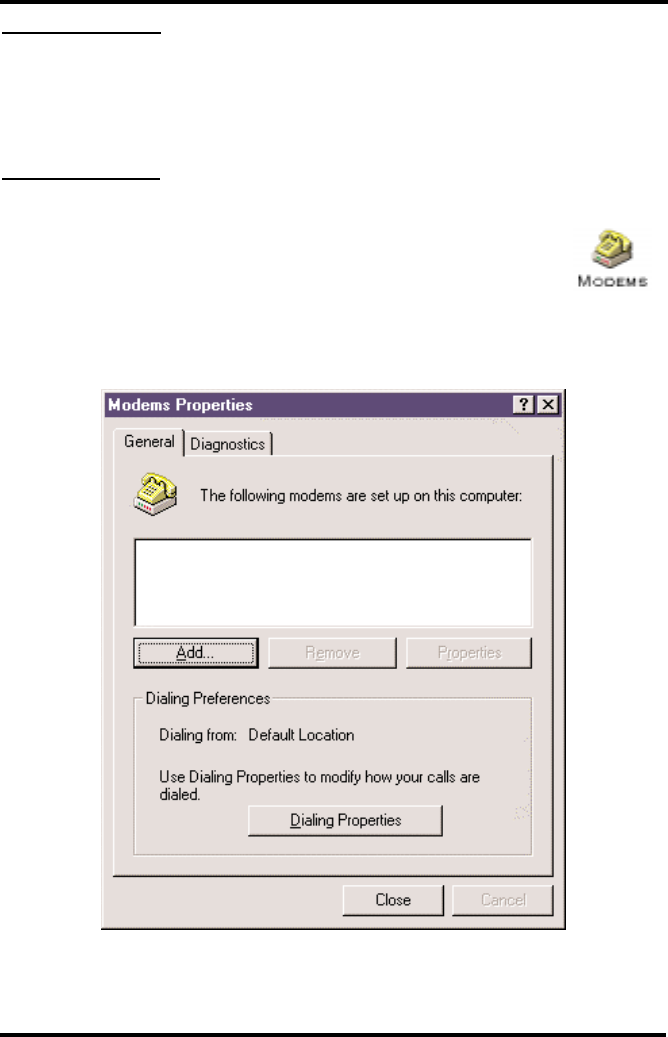
Requirements
•• GSM account with your network service provider including a Data/Fax facility.
••PC/Laptop/ Notebook with Com Port.
••Windows 95
NOTE: When all of the above have been satisfied, you may proceed.
Modem Setup
1) Power on your PC/laptop and start Windows 95.
2) Using the PC pointing device, press the "START" button, select
"SETTINGS" and then "CONTROL PANEL". Once the Control Panel
window appears double click the MODEMS icon button. The modem
properties window will appear.
NOTE: A data card modem device may appear in the list of installed modems.
3) Click the ADD button to install a new modem device for the phonecell.
Appendix A: How to Setup PC Serial Ports
for Phonecell Digital Fax/Data
SX4e GSM 1900 43 USER MANUAL
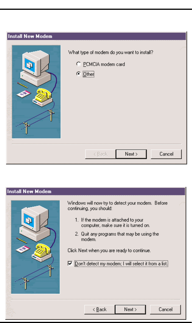
Appendix A: Phonecell Digital Fax/Data - continued
SX4e GSM 1900 44 USER MANUAL
4) The install new modem window may appear asking for the type of modem to
install. Click on "Other" followed by clicking the NEXT button. If this window
does not appear, go to Step 5.
5) The install new modem window will appear. Then, click on the "Don't detect my
modem option" followed by clicking the NEXT button.
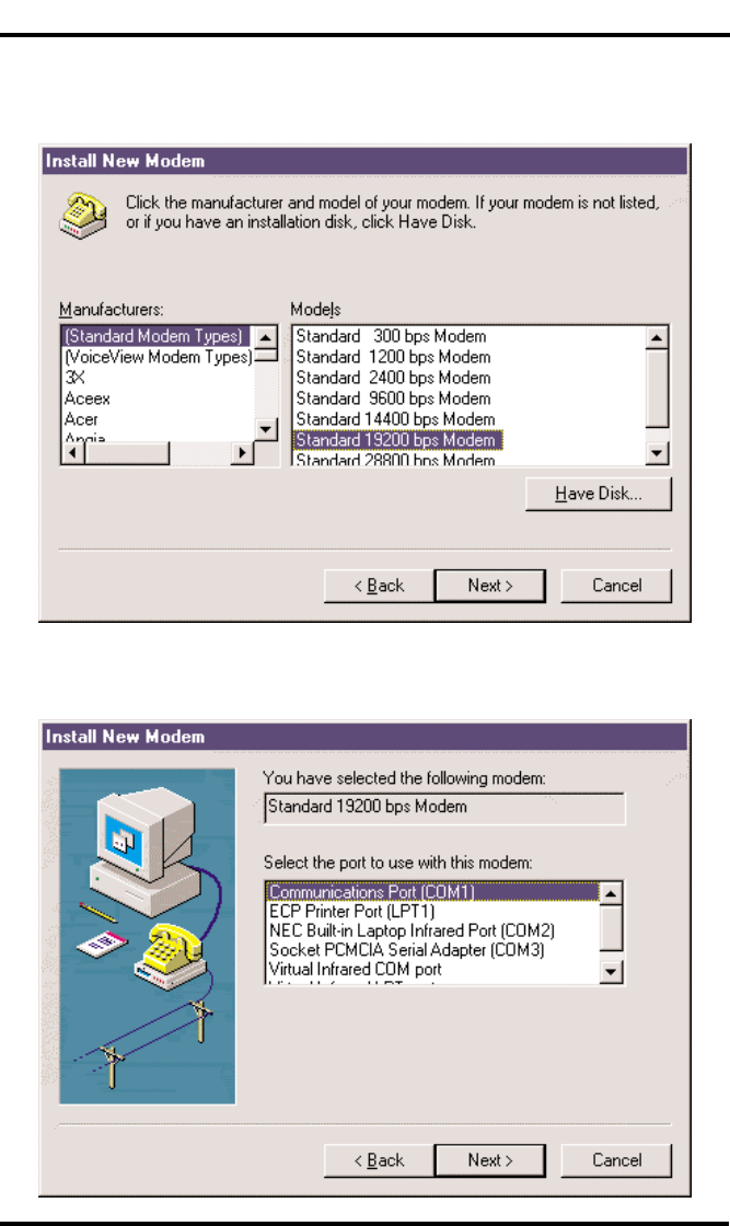
6) The install new modem will update again to select the manufacturer and
modem model. Click on "Standard Modem Types" from the manufactures list
followed by "Standard 19200 bps Modem" from the model list. Then click on
the NEXT button.
7) The install new modem will update to select the com port. Click on the avail-
able serial port and then click on the "Next" button. Windows 95 will create a
modem configuration file for the phonecell. This may take several minutes.
Appendix A: Phonecell Digital Fax/Data - continued
SX4e GSM 1900 45 USER MANUAL
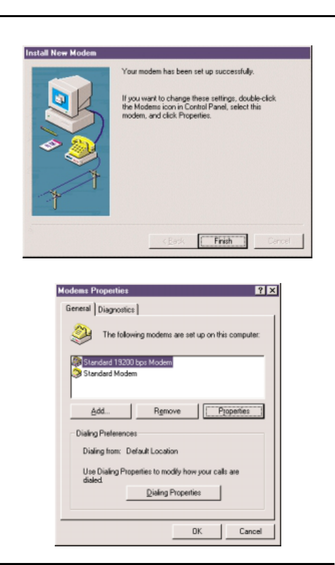
8) The Install New Modem window will update again. Click on Finish to proceed.
9) The Modems Properties window should appear. Click on the Properties button.
Appendix A: Phonecell Digital Fax/Data - continued
SX4e GSM 1900 46 USER MANUAL
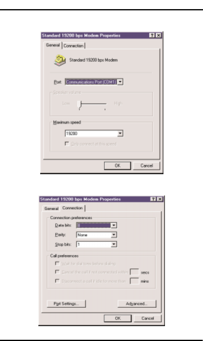
10) The Standard 19200 bps Modem Properties window will open in the General
tab. Set as shown with the com port you have selected.
11) Then click on the Connection tab. Set as shown below.
Appendix A: Phonecell Digital Fax/Data - continued
SX4e GSM 1900 47 USER MANUAL
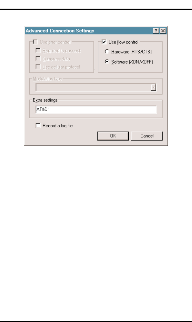
12) Click on the Advanced button. Set as shown.
13) Click on OK and Close to back out of each window. Your modem is now set up.
Appendix A: Phonecell Digital Fax/Data - continued
SX4e GSM 1900 48 USER MANUAL

©2001 TELULAR CORPORATION
56021902