Temco Tool Dv5200Mb Users Manual 78674 DV5200MBN
2015-02-03
: Temco-Tool Temco-Tool-Dv5200Mb-Users-Manual-461333 temco-tool-dv5200mb-users-manual-461333 temco-tool pdf
Open the PDF directly: View PDF ![]() .
.
Page Count: 40
INSTALLER / CONSUMER
SAFETY INFORMATION
PLEASE READ THIS MANUAL
BEFORE INSTALLING AND
USING APPLIANCE
WARNING!
IF THE INFORMATION IN THIS
MANUAL IS NOT FOLLOWED
EXACTLY, A FIRE OR EXPLO-
SION MAY RESULT CAUSING
PROPERTY DAMAGE, PERSON-
AL INJURY OR LOSS OF LIFE.
FOR YOUR SAFETY
Installation and service must
be performed by a qualified
installer, service agency or the
gas supplier.
WHAT TO DO IF YOU SMELL GAS:
• Do not try to light any appliance.
• Do not touch any electric switch; do not
use any phone in your building.
• Immediately call your gas supplier from
your neighbor’s phone. Follow the gas
suppliers instructions.
• If you cannot reach your gas supplier
call the fire department.
DO NOT STORE OR USE GASO-
LINE OR OTHER FLAMMABLE
VAPORS AND LIQUIDS IN THE
VICINITY OF THIS OR ANY OTH-
ER APPLIANCE.
WARNING: Improper installation, ad-
justment, alteration, service or main-
tenance can cause injury or property
damage. Refer to this manual. For
assistance or additional information,
consult a qualified installer, service
agency or the gas supplier.
Direct Vent Zero Clearance
Gas Fireplace Heater
Model: DV5200MB
78674
DV5200
cover
6/05 djt
Homeowner’s Installation and
Operating Manual
U.S. Patents: 5,669,374; 5,562,088; 6,138,667;
Can. Patent: 2,139,684
78674 5/08 Rev. 10
INSTALLER: Leave this manual with the appliance.
CONSUMER: Retain this manual for future reference.

2
Temco DV5200 Series
78674
Table of Contents
PLEASE READ THE INSTALLATION & OPERATING INSTRUCTIONS BEFORE USING APPLIANCE.
Thank you and congratulations on your purchase of a Temco Fireplace Products fireplace.
While we have written these instructions as accurately and thoroughly as possible, they may not cover every system, variation or
contingency. Also, questions of interpretation may arise. For more information, solutions to particular problems or clarifications,
contact your local distributor or the manufacturer. See the unit rating plate for whom to contact.
IMPORTANT: Read all instructions and warnings carefully before starting installation. Failure to follow these instructions
may result in a possible fire hazard and will void the warranty.
Installation & Operating Instructions
General Information, Cautions, Warnings ............................................................. 3
Requirements for the Commonwealth of Massachusetts ...................................... 4
Fireplace Dimensions ............................................................................................ 5
Locating the Fireplace ........................................................................................... 6
Framing & Finishing .............................................................................................. 6
Clearance to Combustibles ................................................................................... 7
Combustible Sidewall Clearance .......................................................................... 7
Mantels .................................................................................................................. 7
Surround Material .................................................................................................. 7
Gas Specifications................................................................................................. 8
Gas Inlet and Manifold Pressures ......................................................................... 8
Gas Line Installation .............................................................................................. 8
General Venting Information
General Venting .................................................................................................... 9
General Venting Information - Termination Location ........................................... 10
Termination Clearances .......................................................................................11
Sidewall (General)Venting Information ................................................................ 12
Flex Venting......................................................................................................... 12
Sidewall (Horizontal) Venting .............................................................................. 13
Flex Vent Offsets ................................................................................................. 13
Flex Vent Through the Roof (Vertical) Applications ............................................. 15
VSK7MH Vertical Flex Vent Kit Installation ......................................................... 15
TDV Series Direct Vent System Installation ........................................................ 16
Sidewall (Horizontal) Venting, General ............................................................... 16
Through the Roof (Vertical) Venting .................................................................... 17
Elbows & Offsets - General ................................................................................ 17
Sidewall (Horizontal) Venting Information ........................................................... 17
Venting Components ........................................................................................... 19
Operating Instructions
Glass Door Removal Procedure ......................................................................... 20
Glass Cleaning .................................................................................................... 20
Louvre Installation ............................................................................................... 20
Optional Extended Face Panel Kit Installation .................................................... 21
Log Installation .................................................................................................... 21
Thermostatic Fan Kit - Optional........................................................................... 22
Electrical Services ............................................................................................... 22
Speed Control Switch .......................................................................................... 22
Millivolt System .................................................................................................... 22
Burner ON/OFF ................................................................................................... 23
Managing Heat Output ........................................................................................ 23
Fan Operation ..................................................................................................... 23
Flame Characteristics .......................................................................................... 23
Lighting & Operating Instructions ........................................................................ 24
Troubleshooting ................................................................................................... 25
Fuel Conversion .................................................................................................. 29
Maintenance
Unit Adjustment ................................................................................................... 32
Maintenance ........................................................................................................ 32
Replacement Parts ........................................................................................................ 34
Servicing .............................................................................................................. 35
Warranty .......................................................................................................................... 36
Installation and Startup Checklist ................................................................................. 37
Warranty Registration ................................................................................................... 39
3
Temco DV5200 Series
78674
Installation & Operating Instructions
A manufactured (mobile) home OEM installation must
conform with the Manufactured Home Construction and
Safety Standard, Title 24CFR, Part 3280, or, when such
a standard is not applicable, the Standard for Manufac-
tured HOme Installations, ANSI/NCSBCS A225.1, or
Standard for Gas Equipped Recreational Vehicles and
Mobile Housing, CSA Z240.4.
This gas appliance must be installed by a qualified
installer in accordance with local building codes or, in
the absence of local codes, with the current CSA B149.1
Installation Code (in Canada) or the current National Fuel
Gas Code Z223.1/NFPA 54 when installed in the United
States.
This appliance, when installed, must be elecrically con-
nected and grounded in accordance with local codes
or, in the absence of local codes, with the current CSA
C22.1 Canadian Electrical Code: ANSI NFPA 70-1987
when installed in the United States.
FOR SAFE INSTALLATION AND OPERATION PLEASE
NOTE THE FOLLOWING:
1 . This appliance gives off high temperatures and should be
located out of high traffic areas and away from furniture and
draperies.
2. Children and adults should be alerted to the hazards of the
high surface temperatures of this appliance and should stay
away to avoid burns or ignition of clothing.
3. CAUTION: Due to high glass surface temperature, chil-
dren should be carefully supervised when in the same
room as your appliance.
This appliance may be installed as an OEM instal-
lation in a manufactured (mobile) home and must
be installed in accordance with the manufacturer’s
instructions and the Manufactured Home Con-
struction And Safety Standard, Title 24 CFR, Part
3280 or Standard for Installation in Mobile Homes,
CAN/CSA Z240MH.
This appliance is only for use with the type of gas
indicated on the rating plate. A conversion kit is
supplied with the appliance.
IMPORTANT:
PLEASE READ THE FOLLOWING CAREFULLY
Remove any plastic from trim parts before turning the
fireplace ON.
It is normal for fireplaces fabricated of steel to give off
some expansion and/or contraction noises during the
start up or cool down cycle. Similar noises are found
with your furnace heat exchanger or car engine. It
is not unusual for your gas fireplace to give off some
odor the first time it is burned. This is due to the
manufacturing process.
Please ensure that your room is well ventilated
-open all windows.
It is recommended that you burn your fireplace for at
least four (4) hours the first time you use it. If the op-
tional fan kit has been installed, place the fan switch
in the “OFF” position during this time.
WARNING: Check with your electronics manufac-
turer before installing a television or other electronic
device above this fireplace.
�
4. Under no circumstances should this appliance be modified.
Parts removed for servicing should be replaced prior to
operating this appliance again.
5. Installation and any repairs to this appliance must be
performed by a qualified installer, service agency or gas
supplier. A professional service person should be contacted
to inspect this appliance annually.
6. Control compartments, burners and air passages in this ap-
pliance should be kept clean and free of dust and lint. Make
sure the gas valve and pilot light are turned off before you
attempt to clean this appliance.
7. The venting system (chimney) of this appliance should be
checked at least once a year and if needed your venting
system should be cleaned.
8. Keep the area around your appliance clear of combustible
materials, gasoline and other flammable vapor and liquids.
This appliance should not be used as a drying rack for cloth-
ing, nor should Christmas stocking or decorations be hung
in the area of it.
9. Under no circumstances should any solid fuels (wood, coal,
paper or cardboard etc.) be used in this appliance.
DV5200
Certified To
ANSI Z21.88-2005 / CSA 2.33-2005 / UL 307B
Vented Gas Fireplace Heater
10. For safe operation, the glass door must be closed.
11. Do not use this heater if any part has been under water.
Immediately call a qualified service technician to inspect the
heater and to replace any part of the control system and any
gas control which has been under water.
12. Do not operate appliance unless completely installed as per
installation instructions.
13. This appliance may be used in a bedroom installation. Install
in accordance with local building codes and regulations.
14. Never use your appliance as a cooking device.
Proposition 65 Warning: Fuels used in gas, wood-
burning or oil fired appliances, and the products of
combustion of such fuels, contain chemicals known to
the State of California to cause cancer, birth defects
and other reproductive harm.
California Health & Safety Code Sec. 25249.6

4
Temco DV5200 Series
78674
Installation & Operating Instructions
Requirements for the Commonwealth of
Massachusetts
All gas fitting and installation of this heater shall only be
done by a licensed gas fitter or licensed plumber.
For all side wall horizontally vented gas fueled
equipment installed in every dwelling, building or
structure used in whole or in part for residential
purposes, including those owned or operated by the
Commonwealth and where the side wall exhaust vent
termination is less than seven (7) feet above finished
grade in the area of the venting, including but not limited
to decks and porches, the following requirements shall
be satisfied:
Installation of Carbon Monoxide Detectors
At the time of installation of the side wall horizontal
vented gas fueled equipment, the installing plumber
or gas fitter shall observe that a hard wired carbon
monoxide detector with an alarm is installed on each
additional level of the dwelling, building or structure
served by the side wall horizontally vented gas fueled
equipment. It shall be the responsibility of the property
owner to secure the services of qualified licensed
professionals for the installation of hard wired carbon
monoxide detectors.
In the event that the side wall horizontally vented gas
fueled equipment is installed in a crawl space or an
attic, the hard wired carbon monoxide detector with
alarm and battery back-up may be installed on the next
adjacent floor level.
In the event that the requirements of this subdivision
can not be met at the time of completion of installation,
the owner shall have a period of thirty (30) days
to comply with the above requirements; provided,
however, that during said thirty (30) day period, a
battery operated carbon monoxide detector with an
alarm shall be installed.
Approved Carbon Monoxide Detectors
Each carbon monoxide detector as required in
accordance with the above provisions shall comply with
NFPA 720 and ANSI/UL 2034 listed and IAS certified.
Signage
A metal or plastic identification plate shall be
permanently mounted to the exterior of the building at
a minimum height of eight (8) feet above grade directly
in line with the exhaust vent terminal for the horizontally
vented gas fueled heating appliance or equipment. The
sign shall read, in print size no less than one-half (1/2)
inch in size, “GAS VENT DIRECTLY BELOW, KEEP
CLEAR OF ALL OBSTRUCTIONS”.
Inspection
The state or local gas inspector of the side wall
horizontally vented gas fueled equipment shall not
approve the installation unless, upon inspection, the
inspector observes carbon monoxide detectors and
signage installed in accordance with the provisions of
248 CMR 5.08(2)(a)1 through 4.
Exemptions
The following equipment is exempt from 248 CMR
5.08(2)(a)1 through 4:
• The equipment listed in Chapter 10 entitled
“Equipment Not Required To Be Vented” in the most
current edition of NFPA 54 as adopted by the Board;
and
• Product Approved side wall horizontally vented gas
fueled equipment installed in a room or structure
separate from the dwelling, building or structure
used in whole or in part for residential purposes.
MANUFACTURER REQUIREMENTS
Gas Equipment Venting System Provided
When the manufacturer of Product Approved side
wall horizontally vented gas equipment provides a
venting system design or venting system components
with the equipment, the instructions provided by the
manufacturer for installation of the equipment and the
venting system shall include:
• Detailed instructions for the installation of the venting
system design or the venting system components;
and
• A complete parts list for the venting system design or
venting system.
Gas Equipment Venting System NOT Provided
When the manufacturer of a Product Approved side
wall horizontally vented gas fueled equipment does
not provide the parts for venting the flue gases, but
identifies “special venting systems”, the following
requirements shall be satisfied by the manufacturer:
• The referenced “special venting system” instructions
shall be included with the appliance or equipment
installation instructions; and
• The “special venting systems” shall be Product
Approved by the Board, and the instructions for
that system shall include a parts list and detailed
installation instructions.
A copy of all installation instructions for all Product
Approved side wall horizontally vented gas fueled
equipment, all venting instructions, all parts lists
for venting instructions, and/or all venting design
instructions shall remain with the appliance or
equipment at the completion of the installation.
5
Temco DV5200 Series
78674
S - Min. Rough Opening Width
Min.
Rough
Opening
Height
Min.
Rough
Opening
Depth
A
C
L
4" (102 mm) Dia.
7" (178 mm) Dia.
1/2" (13 mm)
Q
Q
P
TI
J
R
B
K
L
M
N
C
H
E
F
G
K
LM
N
76657
DV1000
DV1200
DV1400
specs
12/3/03 djt
O
D
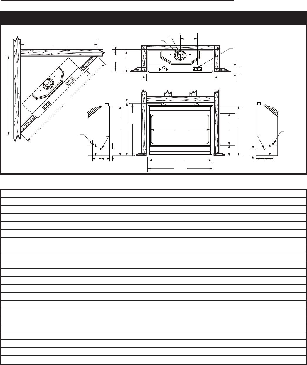
Fireplace Dimensions
Fig. 1 Fireplace specifications and framing dimensions.
NOTE: Flex pipe dimaeters are
4” for inner pipe and 7” for outer
pipe.
Bottom Gas Line Access
Gas
Line
Access
Gas Line
Access J Box
Access
J Box
Access
Ref. DV5200MBN
A 35³⁄₄” (908 mm)
B 33” (838 mm)
C 32³⁄₄” (832 mm)
D 34¹⁄₂” (876 mm)
E 21³⁄₈” (543 mm)
F 6¹⁄₄” (159 mm)
G 33” (838 mm)
H 34¹⁄₄” (870 mm)
I 19¹⁄₄” (489 mm)
J 13³⁄₈” (340 mm)
K 1⁵⁄₈” (16 mm)
L 5⁵⁄₈” (143 mm)
M 5¹⁄₂” (140 mm)
N 4¹⁄₂” (114 mm)
O 3” (76 mm)
P 73¹⁄₂” (1867 mm)
Q 51³⁄₄” (1315 mm)
Framing Dimensions
R 34³⁄₄” (883 mm)
S 36” (914 mm)
T 19¹⁄₂” (495 mm)

6
Temco DV5200 Series
78674
X
T175
rough opening
depth
vertical vent
12/3/03 djt
1” (25 mm)
Minimum Air Space
Clearance to Com-
bustible Materials
Vent System “X”
TEMCO 4/7 Flex 23¹⁄₂”
(597 mm)
TEMCO 4/7 Rigid 24¹⁄₂”
(622 mm)
DuraVent 4/6-5/8 GS 23¹⁄₂”
(597 mm)
T175
Fig. 2 Minimum framing depths with vertical takeoff.
10"
(273 mm)
Min.
T176
rough opening
depth horizontal
6/05 djt
35”
(911 mm)
Ref. Flue
Outlet
”
(781 mm)
41”
(1054 mm)
21”
(546 mm)
Firestop/Wall Sleeve
Combustible
Construction
Allowed
VEF (Vinyl Siding)
or BEF (Brick)
Extension flange
Vent Terminal
Standoff
T176 2 x 4 or 2 x 6 Framing
Fig. 3 Minimum framing dimensions with horizontal venting.
2. When the appliance is installed directly on carpeting,
tile or other combustible material other than wood
flooring, the appliance shall be installed on a metal
or wood platform.
3. Pull out the nail tabs which are located on each side
of the fireplace. Move the fireplace into position and
secure to the floor with screws or nails through the
holes provided in the bottom flanges of the side cas-
ing. After checking unit for squareness, secure top of
fireplace to the framing with screws or nails using the
nailing tabs provided.
4. Cold climate installation recommendation: when
installing this fireplace against a non-insulated exte-
rior wall or chase, it is recommended that the outer
walls be insulated to conform to applicable insulation
codes. Drywall should be installed around the unit to
prevent insulation from contacting the body.
Note: Never allow the vapor barrier to contact
the outer case of this fireplace or venting.
5. Drywall can be extended flush on the bottom, top
and to the outermost part of the sides of the fire-
place.
6. If you are installing the top vent unit with a 90° elbow
installed, the minimum clearance to combustibles
directly above the 90° elbow is 2” (51 mm).
7. Noncombustible materials such as brick and tile
can be extended across the face of the fireplace. If
brass trim kit is going to be installed, brick and tile
will have to be installed flush with the front of this ap-
pliance.
Locating the Fireplace
Y
EAB
C
D
F
YB
X
LU584-T
Locating unit
12/18/02 djt
X
Fig. 4 Locate gas fireplace.
A) Flat on wall B) Cross Corner C) As an Island
D) As a room divider E) Flat on wall corner F) Exterior wall
Island installation is possible as long as the horizontal portion of the
vent system does not exceed maximum recommended horizontal run
as outlined in the venting chart on Page 10. When you install your
fireplace as in position ‘B’, ‘D’ or ‘E’, (Fig. 1) a minimum of 1” (25mm)
clearance must be maintained from the perpendicular wall and the
front of the appliance.
Framing and Finishing
1. Choose a fireplace location and frame in accordance
with the fireplace dimensions specified on Page 4 of
this manual. When using a surround, the fireplace
must be flush to the wall. Also, allowances must
be made for drywall, tile or any other facing used
around the unit.
7
Temco DV5200 Series
78674
Clearance to Combustibles
Top of unit to ceiling* ................................36” (914 mm)
Front of unit to combustibles ....................36” (914 mm)
Appliance
Top (from standoffs) ................................0” (0 mm)
Bottom .....................................................0” (0 mm)
Side (from standoffs) ................................0” (0 mm)
Back (from standoffs) ...............................0” (0 mm)
Top of Elbow ..........................................2” (51 mm)
* Ceiling height is the minimum height of the room ceiling in front of
the fireplace measured from the top front edge of the fireplace.
Combustible Sidewall Clearance
The perpendicular combustible sidewall or mantel sup-
port leg (surround) clearance is 1³⁄₄” (45 mm) from the
edge of the recessed door opening.
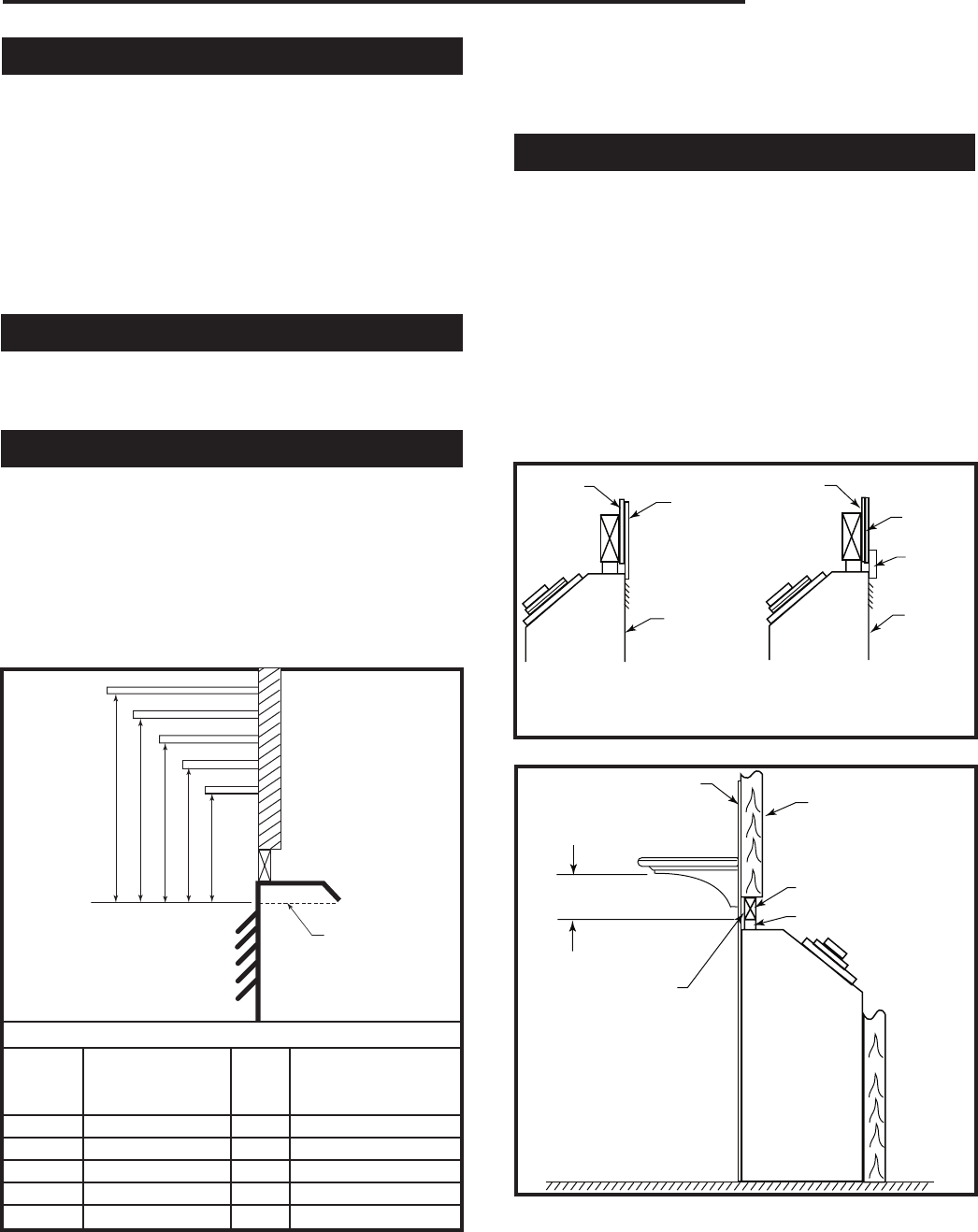
Mantels
The height that a combustible mantel is fitted above the
fireplace is dependent on the depth of the mantel.
For the correct mounting height and widths, refer to
Figure 5.
Noncombustible mantels and legs may be installed at
any height and width around the appliance. When using
paint or lacquer, it must be heat resistant to prevent
discoloration.
A B C D E
V
W
X
Y
Z
Fireplace
T177
Temco DV Mantel
Chart
12/3/03 djt
Top of Louvre
Opening
Mantel Chart
Mantel Shelf Mantel from Top
Ref. or Breast Plate Ref. of Louvre Opening
Depth
V 10” (254 mm) A 12” (305 mm)
W 8” (203 mm) B 10¹⁄₂” (267 mm)
X 6” (152 mm) C 9” (229 mm)
Y 4” (101 mm) D 7¹⁄₂” (191 mm)
Z 2” (51 mm) E 5” (127 mm)
T177
Fig. 5 Combustible mantel minimum installation.
WARNING: Combustible objects must not be placed
on a noncombustible mantel unless the noncombustible
mantel meets the minimum height and width require-
ments for a combustible mantel.
Surround Material
When using materials around the face of the fireplace,
these materials must be suitable to withstand the tem-
peratures which they will encounter. Also these materi-
als must not extend out in front of the face of the unit, in
effect recessing the unit.
If the material used for surround is not flush with the
face of the unit, then the optional surround kits will not
fit properly.
It is recommended that any material used to surround
the face of the fireplace be noncombustible (i.e. ceram-
ic tile, brick, natural stone, etc.). Combustible materials
such as drywall, are permissible.
T178
surround material
12/3/03 djt
Drywall
Tile, Marble, etc.
Drywall
Fireplace
Front
Tile,
Marble,
etc.
Optional
Surround
Kits
Fireplace
Front
Noncombustible Facing
Material Overlap of Front Face
Flush Face Installation
(Recommended when
installing optional trim
surround kits) T178
Fig. 6 Surround material options.
T179
firplace installation
12/3/03 djt
Combustible Material
2 x 4 Stud
2 x 4 Header
Standoff
Minimum Height from
Top Opening to Mantel
Combustible Material
Above Standoff
Optional Hearth T179
Fig. 7 Gas fireplace installation.
Materials such as cultured marble or other synthetic
materials are not recommended as they may discolor,
warp or create odor as a result of exposure to the tem-
peratures of the front of the fireplace.
8
Temco DV5200 Series
78674
Materials such as cultured marble or other synthetic
materials are not recommended as they may discolor,
warp or create odor as a result of exposure to the tem-
peratures of the front of the fireplace.
Gas Specifications
Max. Min.
Gas Input Input
Model Fuel Control BTU/h BTU/h
DV5200MBN Natural Hi/Lo 25,000 17,000
DV5200MBP Propane Hi/Lo 25,000 17,500
Gas Line Installation
This gas appliance should be installed by a qualified in-
staller in accordance with local building codes and with
current CSA-B149.1 installation codes for Gas Burning
Appliances and Equipment in Canada and the National
Fuel Gas Code ANSI Z223.1/NFPA 54 in the U.S.A.*
1. The gas pipeline can be brought in through the bot-
tom or the right or the left side of the appliance. A
hole is provided at all locations to allow for the gas
pipe installation and testing of any gas connection.
2. The gas control inlet is 3/8” NPT. Typical installation
layout for rigid pipe is shown on Page 8.
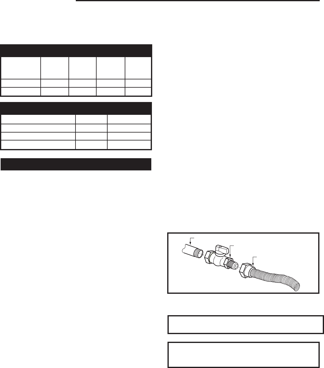
NOTE: All models are equipped with a flex tube
with a shut off valve having a 1/2” NPT inlet. The
flex line with shut off is shipped in the con-
trol valve compartment. Using two wrenches,
tighten the flexible tube at the shut off valve and
at the gas control.
3. When using a flex connector,* use only approved
fittings. When a union is installed, provide easy
access in it’s placement for servicing. Refer to gas
specification for pressure details and ratings.
4. When a vertical section of gas pipe is required for
the installation, a condensation trap is needed. In
Canada see CSA - B149.1 for code details. See the
National Fuel Gas Code ANSI Z223.1/NFPA 54 in
the USA.
5. For natural gas, a minimum of 3/8” iron pipe with
a gas supply pressure of 4.5” w.c. (from the gas
meter). Consult with local gas utility and ANSI223.1/
NFPA 54 if any questions arise concerning pipe
sizes.
6. Turn the gas supply to ‘ON’ and check for leaks. DO
NOT USE OPEN FLAME FOR THIS PURPOSE.
Use an approved leak testing solution.
7. The appliance and its appliance main gas valve
must be disconnected from the gas supply piping
system during any pressure testing of that system at
test pressures in excess of 1/2psig (3.5 KPa).
8. The appliance must be isolated from the gas sup-
ply piping system by closing its equipment shut off
valve during any pressure testing of the gas supply
piping system at test pressures equal to or less than
1/2psig (3.5KPa).
NOTE: The gas line connection may be made of 3/8”
minimum rigid pipe, 3/8” minimum copper pipe or an ap-
proved flex connector. Since some municipalities have
additional local codes, it is always best to consult your
local authorities and the current CSA-B149.1 installa-
tion code in Canada or National Fuel Gas Code ANSI
Z223.1/NFPA 54 in the U.S.A.
*Adhere to the following installation requirements in the State of Mas-
sachusetts:
• The installer must be a licensed plumber or gas fitter.
• Flex connectors must be Massachusetts approved, cannot
exceed 36” (914 mm) in length, must be a minimum 1/2” dia., and
may not penetrate a wall.
FP297A
INSTA VENT FREE
UVHB26 GAS SUPPLY
7/1/98
1/2” Gas Supply
1/2” NPT x 1/2” Flare Shut-off Valve
1/2” Flex Line
(from valve)
FP297a
Fig. 8 Typical gas supply installation.
IMPORTANT: Always check for gas leaks with a
soap and water solution. Do not use open flame
for leak testing.
Gas Inlet and Manifold Pressures
Natural LP (Propane)
Minimum Inlet Pressure 4.5” w.c. 10.8” w.c.
Maximum Inlet Pressure 14.0” w.c. 14.0” w.c.
Manifold Pressure 3.5” w.c. 10.0” w.c.
WARNING: When purging the gas line, the glass
front must be removed.

9
Temco DV5200 Series
78674
General Venting
When locating the vent termination, the minimum vent
clearances must be observed. (Page 9, Fig. 10)
NOTE: Local codes may require different clearances.
It is recommended that the termination not be located
within 24” (305 mm) of garden sheds, fences, decks,
utility buildings or other obstructions.
Do not locate termination cap where excessive snow or
ice build up may occur. Be sure to check vent termina-
tion area after snow falls and clear to prevent accidental
blockage of venting system. When using snow blowers,
make sure snow is not directed towards vent termina-
tion area.
This appliance has a “special vent system”. Check
with local codes or in the absence of same, with CSA
B149.1 installation codes in Canada, or the current
National Fuel Gas Code ANSI Z223.1/NFPA 54 in the
USA, regarding special vent termination clearances.
These fireplaces are certified for use with four types of
venting systems
1. Temco 4” x 7” dia. flex vent.
2. Temco TDV series 4” x 7” dia. rigid vent.
3. Simpson Dura-Vent GS series 4” x 6⁵⁄₈” dia. vent.
Review general venting information in this manual, and
information packed with the venting prior to starting the
installation of the fireplace.
• Termination shall not be recessed into a wall or sid-
ing.
• Horizontal sections must maintain a minimum 1/4”
rise per linear foot of horizontal run.
• Combustible clearances from any horizontal vent
pipe area must be 2” (51 mm) from top of vent, and
1” (25 mm) from sides and bottom.
• Clearance to combustibles from vertical pipe surface
is 1” (25 mm).
10
Temco DV5200 Series
78674
V
V
V
V
V
V
V
X
X
X
D
E
B
B
B
C
BM
B
A
J
K
F
L
VENT TERMINATION AIR SUPPLY INLET AREA WHERE TERMINAL IS NOT PERMITTED
H
I
Fixed
Closed
Fixed
Closed
Operable
Operable Fixed
Closed
V
B
CFM145a
DV Termin Location
5/01/01 Rev. 12/05/01
sta
INSIDE
CORNER DETAIL
V
A
G
V
NN
V
V
G
G
A
CFM145a
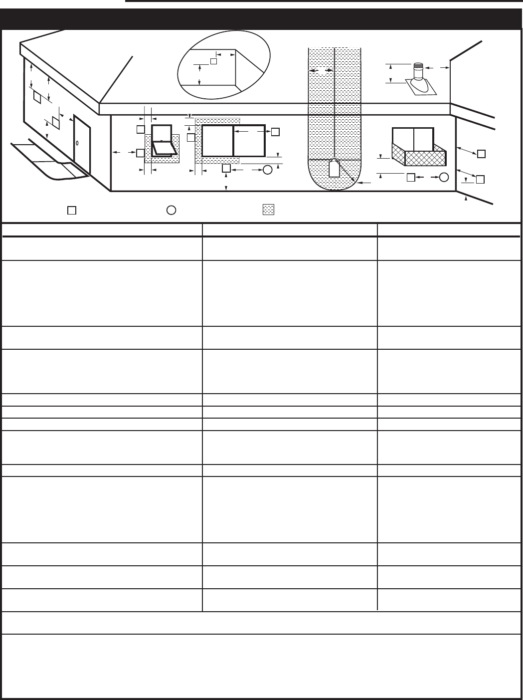
General Venting Information - Termination Location
A = Clearance above grade, veranda, porch, 12” (30 cm) 12” (30 cm)
deck, or balcony
B = Clearance to window or door that may be 6” (15 cm) for appliances 6” (15 cm) for appliances
opened < 10,000 Btuh (3kW), 12” (30 cm) < 10,000 Btuh (3kW), 9”
for appliances > 10,000 Btuh (3kW) and (23 cm) for appliances > 10,000
< 100,000 Btuh (30kW), 36” (91 cm) Btuh (3kW) and < 50,000 Btuh
for appliances > 100,000 Btuh (30kW) (15kW), 12” (30 cm) for
appliances > 50,000 Btuh (15kW)
C = Clearance to permanently closed window 12” (305 mm) recommended to 12” (305 mm) recommended to
prevent window condensation prevent window condensation
D = Vertical clearance to ventilated soffit located
above the terminal within a horizontal 18” (457 mm) 18” (457 mm)
distance of 2 feet (610mm) from the center
line of the terminal
E = Clearance to unventilated soffit 12” (305 mm) 12” (305 mm)
F = Clearance to outside corner see next page see next page
G = Clearance to inside corner (see next page) see next page see next page
H = Clearance to each inside of center line 3’ (91 cm) within a height of 15’ (4.6 m) 3’ (91 cm) within a height of 15’
extended above meter/regulator assembly above the meter/regulator assembly (4.6 m) above the meter/regulator
assy
I = Clearance to service regulator vent outlet 3’ (91 cm) 3’ (91 cm)
J = Clearance to nonmechanical air supply inlet 6” (15 cm) for appliances < 10,000 6” (15 cm) for appliances
to building or the combustion air inlet to any Btuh (3kW), 12” (30 cm) for < 10,000 Btuh (3kW), 9”
other appliances appliances > 10,000 Btuh (3kW) and < (23 cm) for appliances > 10,000
100,000 Btuh (30kW), 36” (91 cm) Btuh (3kW) and < 50,000 Btuh
for appliances > 100,000 Btuh (30kW) (15kW), 12” (30 cm) for
appliances > 50,000 Btuh (15kW)
K = Clearance to a mechanical air supply inlet 6’ (1.83 m) 3’ (91 cm) above if within 10’
(3 m) horizontally
L = Clearance above paved sidewalk or paved 7’ (2.13 m)† 7’ (2.13 m)†
driveway located on public property
M = Clearance under veranda, porch, deck or 12” (30 cm)‡ 12” (30 cm)‡
balcony
N = Clearance above a roof shall extend a minimum of 24” (610 mm) above the highest point when it passes through the roof
surface, and any other obstruction within a horizontal distance of 18” (457 mm).
1 In accordance with the current CSA-B149 Installation Codes
2 In accordance with the current ANSI Z223.1/NFPA 54 National Fuel Gas Codes
† A vent shall not terminate directly above a sidewalk or paved driveway which is located between two single family dwellings and serves both dwell ings
‡ only permitted if veranda, porch, deck or balcony is fully open on a minimum 2 sides beneath the floor:
NOTE: 1. Local codes or regulations may require different clearances.
2. The special venting system used on Direct Vent Fireplaces are certified as part of the appliance, with clearances tested and approved by the
listing agency.
Canadian Installations1 US Installations2
Fig. 9 Vent termination clearances.
11
Temco DV5200 Series
78674
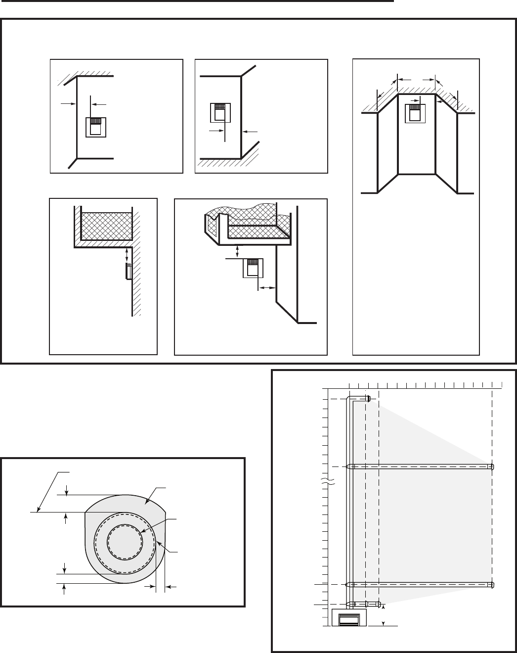
Outside Corner
Inside Corner
Termination Clearances
Termination clearances for buildings with combustible and noncombustible exteriors.
A =
Combustible
6"(152mm)
Noncombustible
2"(50mm)
B =
Combustible
6"(152mm)
Noncombustible
2"(50mm)
A
Balcony -
with no side wall
G =
Combustible &
Noncombustible
12"(305mm)
G
Balcony -
with perpendicular side wall
H = 24"(610mm)
J = 20"(508mm)
H
J
B
Recessed Location
C = Maximum depth of 48"
(1219mm) for recessed
location.
D = Minimum width for back wall
of a recessed location.
Combustible 38"(965mm)
Noncombustible 24"(610mm)
E = Clearance from corner in
recessed location.
Combustible 6"(152mm)
Noncombustible 2"(50mm)
C
D
C
E
V
V
Combustible &
Noncombustible
V
V
V
584-15
Fig. 10 Termination clearances.
NOTE: Use only venting systems and components
as certified with the appliance. Use of uncertified vent
systems or components will void the warranty and may
compromise the operation of the fireplace, its systems,
and components as certified with the appliance.
2" (51mm)
1" (25mm)
1"
(25mm)
T181
vent clearances
12/3/03 djt
Top of Vent
Combustibles
NOT Allowed in
Shaded Area
4” Dia. Flue
7” Dia. Intake
Vent
T181
Fig. 11 Vent clearances.
0
5'
46"
(1168mm)
33¹⁄₂"
(851mm)
10'
15'
25'
30'
32'
0 3'5' 10' 15'
T180
DV vent graph
12/3/03 djt
*
A vent guard should be
used whenever the termina-
tion is lower than the speci-
fied minimum or as per local
codes
* Min. Refer to Chart on Page 6
T180
Fig. 12 Venting graph.
12
Temco DV5200 Series
78674
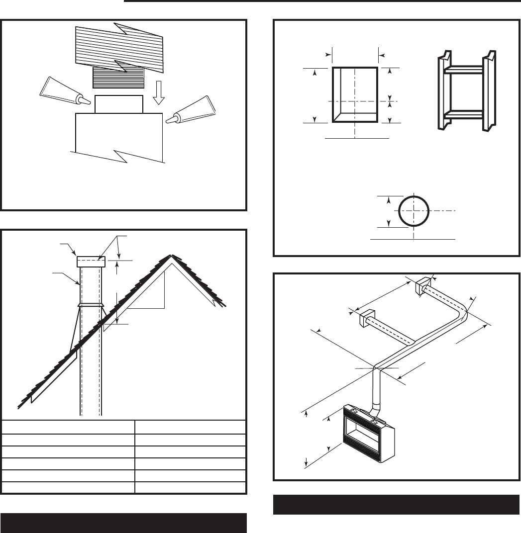
T182
sealant
12/3/03 djt
MILL-PAC
MILL-PAC
NOTE: Apply sealant “Mill-Pac” to inner pipe and “Mill-Pac” or high
temperature silicone sealant to outer pipe. Sealant should be ap-
plied at every joint in the vent system including at the fireplace and
at the vent terminal. T182
Fig. 13 Apply sealant at every joint in vent system.
H
12
x
T183
typical straight up
installation
12/3/03 djt
Gas Vent
Vent Cap Lowest Discharge Opening
Roof Pitch X/12
H (Min.) - Minimum height
from roof to lowest discharge
opening
T183
Roof Pitch H (Min.)
Flat to 6/12 12” (305 mm)
6/12 to 7/12 15” (381 mm)
Over 7/12 to 8/12 18” (457 mm)
Over 8/12 to 16/12 24” (610 mm)
Over 16/12 to 21/12 36” (914 mm)
Fig. 14 Vertical termination location.
Sidewall (General) Venting Information
Figures 15 and 16 show examples of horizontal termi-
nation arrangements using two 90° elbows (Rigid Vent).
NOTE:
1. A maximum of two 90° elbows are permitted.
2. A minimum of 10’ (3 m) vertical from base of unit is
required if two 90° elbows are used.
3. Minimum distance between elbows is 2’ (610 mm).
4. Determine the permitted range of horizontal ter-
mination arrangement by using chart above and
deducting 3’ (914 mm) from the maximum horizontal
distance for the second 90° elbow.
VO584-100
Vent Opening
2/99 djt
Vent Opening for Combustible Wall
9³⁄₄”
(248 mm)
10³⁄₄”
(273 mm)
5⁷⁄₈”
(149 mm)
4⁷⁄₈”
(124 mm)
Fireplace Hearth Framing Detail
Opening for Noncombustible Wall
Rnd.
8” Dia.
(203 mm)
Min.
Fireplace Hearth VO584-100
Fig. 15 Locate vent opening on wall.
33"
(838 mm)
Minimum
53" (1346 mm)
Maximum
28' (8.5 m)
2' (610 mm)
Minimum
B
12" (305 mm)
Minimum
If length "B" is increased,
length "A" must be decreased
by a corresponding amount
T184
sidewall venting
12/3/03 djt
A
10’ (3 m)
Maximum
A vent guard should be used
whenever the termination is
lower than the specified mini-
mum or as per local codes.
T184
Fig. 16 Horizontal vent run.
Flex Venting
• Flex vent shall use the spacer springs as included
every foot to ensure proper vent operation.
• The 4” x 7” flex system may be used for all sidewall
applications and vertical venting up to 35’ (10.7 m).
• Flex shall be properly supported so there are no
sags in the system. Supports must be used at least
every 24” (610 mm) on horizontal section and every
36” (914 mm) on vertical. Wire or metal stripping
may be used to support the venting.
• For 4” x 7” flex, the 7” flex has an outside diameter
of 7¹⁄₂” (191 mm) and if installed in a chase the in-
side diameter of the chase should be 9¹⁄₂” (241 mm)
minimum.
13
Temco DV5200 Series
78674
• Lengths of co-axial flex may be joined together using
a flex connector kit (GFPVCK) only, maximum 1 kit
per installation.
An extension collar is included with side wall cap kits to
simplify the connection of the flex pipe to the fireplace.
Refer to Page 13, Figure 22.
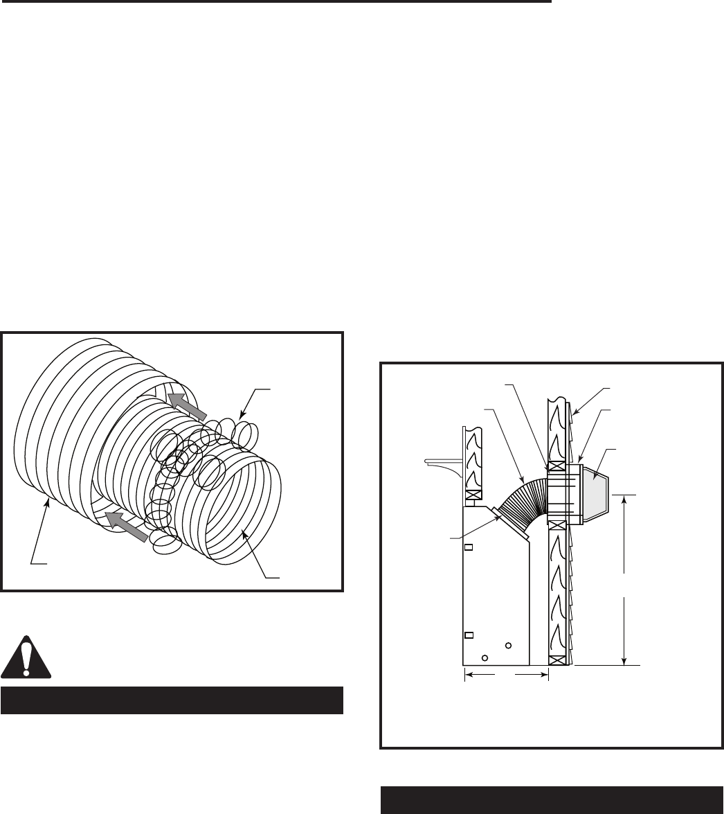
ATTENTION: Spacer springs must be installed when
installing flexible venting systems.
Wrap spacer spring around flex flue pipe and overlap
spring ends approximately 2” (610 mm). Tie one end
over the other like a shoelace tie, then reverse direc-
tion of spring ends. Lift up hooped spring and slide both
spring ends underneath hooped spring. Spring spacers
should be spaced at approximately 12” (305 mm) inter-
vals for the length of pipe system. Once the springs are
placed around the flue pipe, slide the flue section with
spacer springs into the outer flex pipe.
◆ HFTK (Trapezoid Termination Cap)
The vent starter kit contains the following:
• Horizontal termination
• Wall thimble
• Extension collar
NOTE: HIGH WIND AREAS All termination caps are
tested and certified for wind conditions up to 40 mph
(64 k/h).
A Vinyl Extension Frame Kit No. VEF is required for all
installations where vinyl siding is used with the HFTK
Kit or HSQ47 Horizontal Vent Termination. If a Vinyl
Extension Frame Kit No. VEF is used, measure to out-
side surface of wall without siding and add 2 additional
inches (51mm) to the venting length.
A brick extension kit No. BEF is available to extend the
horizontal vent terminal HSQ47 or HFTK kit terminal
beyond the brick surface. If the BEF extension is used,
measure to the outside surface of the framed wall and
add 4 additional inches to the venting length.
T185
spacer springs
12/3/03 djt
Flex Outer Vent
Spacer
Springs
Flex Flue
T185
Fig. 17 Wrap spacer spring around flex flue pipe, overlapping
ends.
CAUTION: Care must be taken when tight-
ening clamps so the flex does not tear at
clamp location.
Sidewall (Horizontal) Venting
For side wall (Horizontal) venting, this appliance is ap-
proved for use with a 7” x 4” flexible venting system with
spacers.
Clearance to combustible material from the pipe is 1”
(25 mm). Sides and bottom, 2” clearance from the top.
NOTE: O.D. of pipe is 7¹⁄₂” (191 mm).
Horizontal Vent Kits
◆ CDV-HSK (Round Termination Cap)
The vent starter kit contains the following:
• Horizontal termination
• Wall thimble
• 36” of 7” x 4” flex with spacers and clamps.
• Extension collar
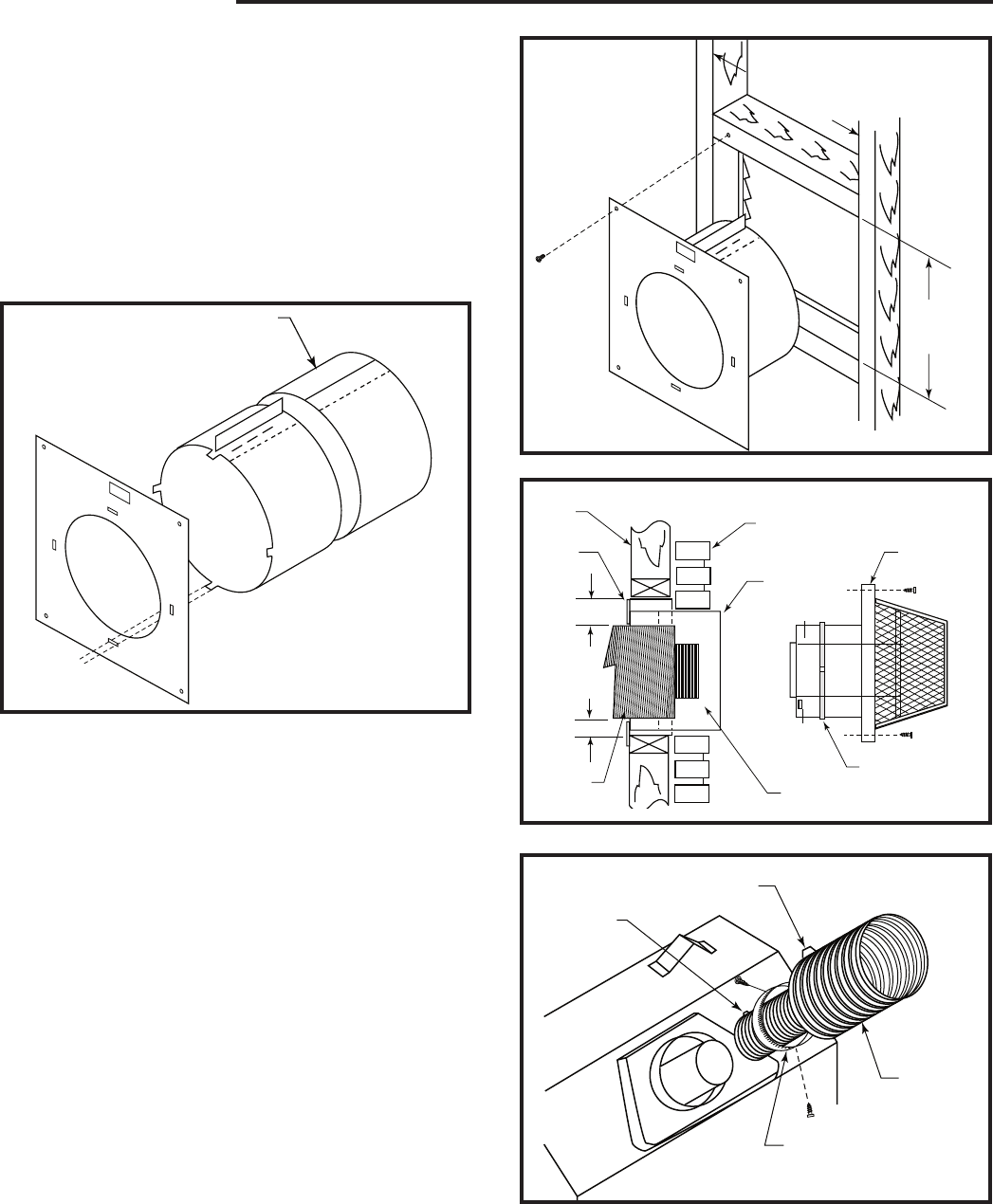
A
B
T176a
horizontal venting
mins
12/4/03 djt
Firestop/Wall Sleeve
(included with HFTK)
GFP74FV3
(3’ (914 mm) Flex
Pipe 4” x 7” Dia.)
Exterior Wall
VEF (or BEF) Vinyl
(or Brick) Extension
Flange
HFTK Vent
Termination Kit
Vent Clamp
(Included
with HFTK)
NOTE: Typical terminal height “B” is 60” (1.5 m) for model
DV5200 with dimension “A” up to 36” (914 mm). Please
refer to minimum framing dimensions with horizontal venting
chart on Page 5.
T176a
Fig. 18 Typical direct vent gas fireplace with horizontal vent-
ing.
Flex Vent Offsets
Each installation assumes the use of (1) 45° (bend)
starting off top of unit.
To determine the amount or length of flex vent you need
for a given installation, add the total offset dimension to
the total rise needed. Then add 1 ft. (305 mm) for every
45° bend and/or 2’ (610 mm) for each 90° bend.
14
Temco DV5200 Series
78674
No more than (4) 90° and (2) 45° offsets are to be used
per installation. Vent terminal cap location should be in
accordance with the Venting Graph chart and the Verti-
cal Termination Location information.
1. Measure the total wall thickness. Determine whether
or not the thimble extension is needed. If the com-
bustible wall depth is over 5” (127 mm), the exten-
sion should be used. (Fig. 19)
2. Assemble wall thimble with thimble extension flange
to top. Mate thimble to wall plate with the four tabs
provided. Bend tabs over to secure. (Fig. 19)
T186
Telescope extension
12/4/03 djt
Telescope Extension
T186
Fig. 19 The telescope extension must be used if wall thick-
ness is over 5” (127 mm).
3. Install the wall thimble assembly through the framed
opening so the firestop plate is on the interior wall.
(Fig. 20) Telescope section should extend all the way
through wall.
4. Step 1: Apply Mill-Pac to 4” flue inner pipe on cap.
Step 2: Connect 4” flex flue to flue on cap with
band clamp.
Step 3: Apply silicone sealant to 7” outer pipe on
cap.
Step 4: Slide 7” outer flex over inlet and secure with
band clamp.
5. Secure vent cap terminal to exterior wall with screw
type fasteners as needed. (Fig. 21)
6. Connect corrugated side of the extension collar (7”
dia.) into the 7” dia. flex pipe. (Fig. 22) Place a small
bead of silicone around the collar approximately 1/4”
from the leading edge of the corrugation. Insert the
collar firmly into the flex pipe and secure with the
provided (7” dia.) band clamp.
7. Place a small mill-pac bead around the top edge of
the fireplace flue collar. Then, attach the flex tube
over the flue collar with a 4” dia. band clamp.
9¹⁄₂" (241mm)
10¹⁄₂"
(267mm)
T187
wall thimble
12/5/03 djt
T187
Fig. 20 Install wall thimble with firestop on interior wall.
2" (51mm)
1" (25mm)
T188
vent cap terminal
12/5/03 djt
Inside
Wall
Wall
shield
Flex
Duct
Exterior Wall
Flange at
Top
Thimble Extension
Band Clamp
Terminal
Cap
Assembly
T188
Fig. 21 Secure vent cap terminal to exterior wall.
T189
extension collar
into flex vent
12/5/03 djt
7” (178 mm)
Band Collar
4” (102 mm)
Band Clamp
and Flex Flue
7”
(178 mm)
Flex Vent
Extension Collar
T189
Fig. 22 Insert collar into flex pipe and secure with band clamp.
ATTENTION: Spacer springs must be installed when install-
ing flexible venting system.
15
Temco DV5200 Series
78674
8. To finish connections, place a small bead of silicone
to the outside of the fireplace inlet flange. Then, slide
the extension collar over the inlet flange and secure
with the three (3) screws provided.
NOTE: We recommend driving in two (2) sheet metal
screws at 180° adjacent to the gear clamp at each joint.
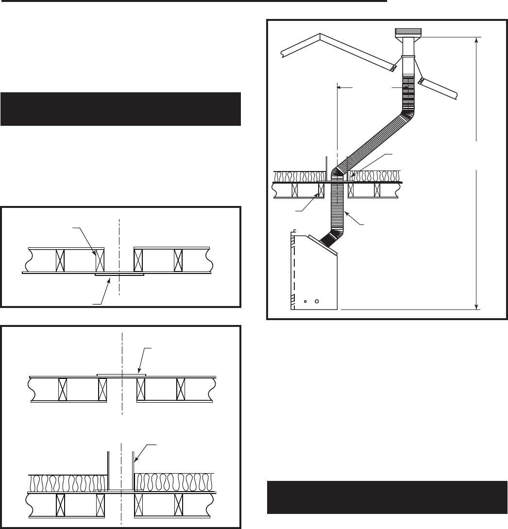
Flex Vent Through the Roof
(Vertical) Applications
All models are approved for:
1. Vertical venting up to 35’ (10.7 m) with 7” x 4” flex.
2. Multiple bends allowed. See section on General
Venting.
3. With each vertical installation, a VSK7MH-2 kit may
be used.
T190
ceiling install
12/5/03 djt
Room Above
Ceiling Level
Ceiling Joist
Firestop T190
Fig. 23 Firestop at ceiling level.
T190
ceiling install
12/5/03 djt
Firestop
Attic Above Ceiling
(Uninsulated)
Attic Above Ceiling
(Insulated) Attic Insulation
Shield
T190
Fig. 24 Attic insulation shield.
6' (1.8m)
Maximum
35' (10.7m)
Maximum
T191
thru the roof
installation
12/5/03 djt
Roof
Attic Insulation
Shield
7” (178 mm) Dia.
Joists
T191
Fig. 25 Typical through-the-roof installation.
The VSK7MH-2 Kit contains:
• Vertical Termination Cap and Storm Collar
• 4”/7” dia. x 24” Rigid Pipe (unitized)
• 7” dia. Roof Support Components
• 10’ Length of 4” x 7” Aluminum Flex Vent w/Clamps
• Adjustable Firestop Thimble Assembly
• 0/12-5/12 Flashing with Storm Collar
• Tube High Temp Sealant
• 7” dia. Inlet Ext. Collar
• Firestop
• Hardware Pack
• Instruction
VSK7MH-2 Vertical Flex
Vent Kit Installation
1. Locate the fireplace.
2. Mark ceiling above unit where flex will come through.
*-REFER TO VERTICAL TERMINATION LOCATION
CHART
3. Ceiling opening should be a minimum of 9¹⁄₂” x 9¹⁄₂”
(241 x 241 mm) and framed to that size.
4. Mark opening in roof and cut a hole minimum 9¹⁄₂” x
9¹⁄₂” (241 x 241 mm) and frame to that size.
5. Place fireplace in proper location and secure to the
floor.
6. Install the firestop thimble assembly at the ceiling
level.
16
Temco DV5200 Series
78674
7. If an attic space (insulated or not) is located above
the ceiling, the firestop should be installed to the
underside of the ceiling. The firestop maintains the
proper air-space clearance from the vent to insula-
tion and building materials. An attic insulation shield
(AS7-8) may be used above the firestop to keep attic
insulation spaced away from the vent system.
8. Rigid pipe section included with vertical termination
must be used in conjunction with the roof support so
that the termination is secure in winds. All vent kit
components can be assembled on the ground first,
then lift complete assembly onto the roof and feed
flex vent down thru the roof opening and firestop
thimble assembly. Then trim off unneeded flex at unit
and make the connection at the fireplace flue and in-
let collars. Make sure vent cap will be in accordance
with the vertical termination location chart. Install the
roof flashing below the shingles across the top half,
and above the shingles on the lower half.
9. Install storm collar and caulk around the pipe.
TDV Series Direct Vent System Installation
• The TDV series vent system is specifically approved
only for Temco Direct-Vent fireplace models with a 4”
(102 mm) diameter flue and a 7” (178 mm) diameter
inlet vent system. The use of uncertified venting will
void warranties and may compromise the operation
and safety of the appliance.
• Termination shall not be recessed into a wall or sid-
ing.
• The vent system shall be properly supported so
there are no sags in the system. Supports must be
used at least every 3’ (914mm) on horizontal section
and every 6’ (1.8m) on vertical.
• Horizontal sections must maintain a minimum 1/4”
rise per linear foot of horizontal run.
• Combustible clearances from any horizontal vent
pipe area must be 2” (51mm) from top of vent, and
1” (25mm) from sides and bottom.
• Clearance to combustibles from vertical pipe surface
is 1” (25mm).
• Prior to securing each vent component, make sure
the sections are pushed together firmly to maintain
vent integrity.
Sidewall (Horizontal) Venting, General
When locating the vent termination, the minimum vent
clearances must be observed.
NOTE: Local codes may require different clearances.
It is recommended that the temination not be located
within 24” (610 mm) of garden sheds, fences, decks,
utility buildings or other obstructions.
Review the “vent termination” section in the appliance
installation instructions.
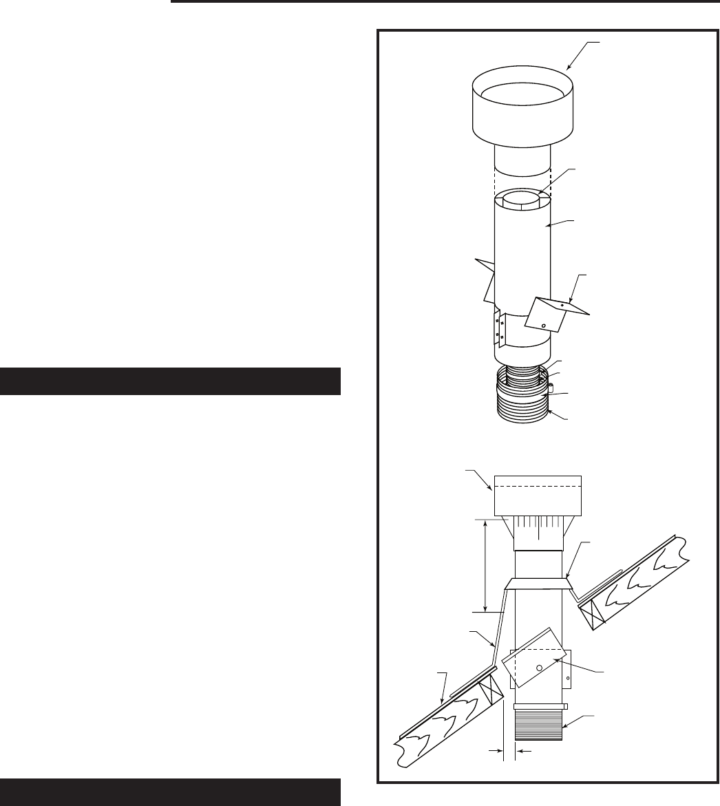
1" (25mm)
Minimum
T192
vertical cap
12/5/03 djt
VT47 Vertical
Vent Cap
4” (102 mm) Dia.
7” (178 mm) Dia.
Vent Pipe Assembly
(VSK7MH-S)
(VSK7)
Vent System Roof
Support / Clamp
Assembly
Band Clamp
4” (102 mm) Dia. Flex Flue
Band Clamp
7” (178 mm) Dia.
Flex Vent
Vent Cap
8: (203 mm)
Dia. Pipe
Must Extend
Through Roof
Flashing
Roof Flashing
Roof
Exterior
Storm Collar
Roof Support
Assembly
7” (178 mm) Dia.
Flex Vent
Clearance to Combustibles T192
Fig. 26 Through the roof installation.
NOTE: If offset is required, the upper 45° bend (elbow)
must be supported with an offset support. Support flex
every 3’ (914 mm) when vertical venting.
17
Temco DV5200 Series
78674
Do not locate vent terminal where excessive snow or
ice build up may occur. Be sure to check vent termina-
tion area after snow falls and clear to prevent accidental
blockage of venting system. When using snow blowers,
make sure snow is not directed towards vent termina-
tion area.
The TDV series is considered a “special vent system”.
Check with local codes or in the absence of same, with
CSA B149.1 installation codes regarding special vent
termination clearances.
NOTE: Flexible and rigid vent system components are
not interchangable unless otherwise specified in the
venting instructions.
NOTE: Additional venting information regarding clear-
ances, terminal locations, and safety information is
contained in the installation and operationg instructions
packaged with the appliance.
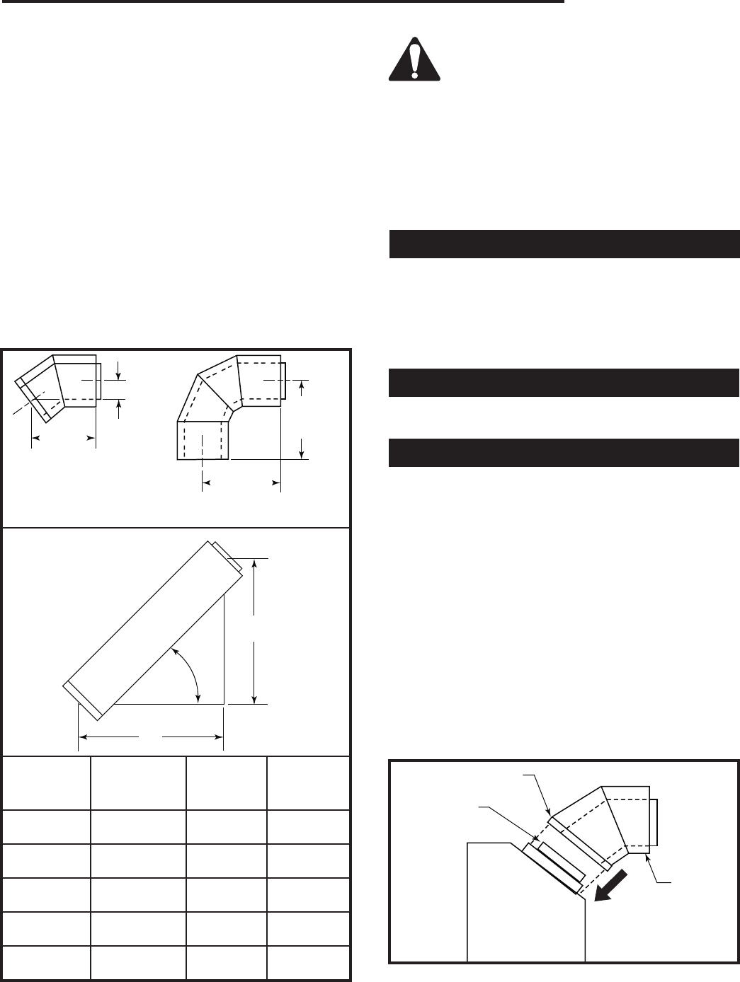
3³⁄₈" (86mm)
7⁷⁄₈"
(200mm)
8"
(203mm)
9¹⁄₈"
(232mm)
T193
offset and rise elbows
12/5/03 djt
TDV45S 45°
Elbow 90° Elbow
B
A
T194
vent offset
12/5/03 djt
Vent Offset @ 45°
T193
45°
Installed
Vent Pipe True Length “A” “B”
Component Gain Rise Run
TDV6 4” 2¹¹⁄₁₆” 2¹¹⁄₁₆”
(102 mm) (68 mm) (68 mm)
TDV12 10” 7¹⁄₁₆” 7¹⁄₁₆”
(254 mm) (179 mm) (179 mm)
TDV18 16” 11⁵⁄₁₆” 11⁵⁄₁₆”
(406 mm) (287 mm) (287 mm)
TDV36 34” 24¹⁄₁₆” 24¹⁄₁₆”
(864 mm) (611 mm) (611 mm)
TDV48 46” 32¹⁄₂” 32¹⁄₂”
(1168 mm) (826 mm) (826 mm)
T194
IMPORTANT: Do not mix vent system compo-
nents with components for other vent systems.
NOTE: Use only venting systems and components
as certified with the appliance. Use of uncertified vent
systems or components will void the warranty and may
compromise the operation of the fireplace, its systems,
and components as certified with the appliance. Use
of uncertified vent systems or components will void the
warranty and may compromise the operation of the
fireplace.
Through the Roof (Vertical) Venting
When the venting penetrates a roof, the system must
be insalled in accordance with the current CSA B149.1
installation code (in Canada) or the current National
Fuel Gas Code, ANSI Z223.1/NFPA 54 (in U.S.A.).
SEE CHART FOR VERTICAL TERMINATION LOCA-
TION.
Elbows & Offsets - General
Each installation assures the use of one 45° elbow hori-
zontal or vertical (off top of unit).
Sidewall (Horizontal) Venting Information
1. Make sure fireplace location and termination location
are consistent with requirements for terminations
and vent runs.
2. Secure unit to the floor.
3. Locate vent opening in wall. Maintain 2” (51 mm)
clearance to top of vent from combustibles. Install
wall thimble per instructions supplied with Horizontal
Vent Kit. Refer to Pages 12 & 13, Figures 19 and 20
for wall thimble installation.
4. Attach vent components beginning with a TDV45S
elbow. Apply high temperature sealant to the out-
side leading edge of the fireplace flue pipe, then
install the TDV45S starter elbow and secure it to the
fireplace with the three (3) screws (provided) through
the outer pipe flange and into the fireplace 7” (178 mm)
dia. starter flange.
T196
Horizontal takeoff
12/5/03 djt
Screw Location
Apply Sealant
to Flue Pipe
Horizontal
Take Off
Illustrated
T196
Fig. 27 Apply high temperature sealant to outside of the flue
pipe.
18
Temco DV5200 Series
78674
5. Align the flue and inlet pipes of each vent section
to the mating component, then slide the sections
together. Before a joint in the system is secured,
push the vent components together using moderate
force to ensure joint overlap of approximately 1¹⁄₂”
(38 mm).
6. Secure vent components with a minimum of three (3)
screws at each joint (pipe joint to pipe, joint sealants
are not required). Never use screws in vent systems
longer than 1” (25 mm).
7. Vent sections and elbows may be rotated 360° prior
to securement to obtain the desired direction of vent
run, and provide flexibility.
8. Make sure all horizontal sections have no sags and
maintain a minimum 1/4” (6mm) rise per linear foot.
9. Using the high temperature sealant provided, apply
a small bead of sealant to both the flue and inlet pipe
extensions on the vent terminal (cap) and install the
horizontal vent terminal to side of building with four
(4) screws provided.
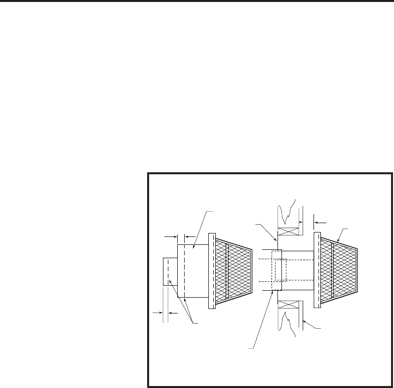
10. If the last section of vent pipe does not allow the
vent terminal to seat against the outside wall, it will
be necessary to replace the last vent section with a
shorter vent section. In addition, you may also mea-
sure the distance between the wall and back flanges
of the terminal base plate. Next, trim off the terminal
flue and inlet pipes to the dimension measured and
reinstall the vent terminal.
A
A
A
T197
short vent terminal
12/8/03 djt
Inlet Pipe
Wall Thimble HSQ47
Vent
Terminal
Cut Lines
Push vent terminal in as
far as vent system will
allow. Use Dimension “A”
as the dimensin needed
to trim off the terminal flue
and inlet pipe.
Exterior Wall
T197
The flue pipe and inlet pipe of the vent terminal may be
cut back equal amounts as illustrated by Dimension “A”.
Fig. 28 Cut the terminal flue and inlet pipes to shorten the
vent section.
ATTENTION: Vent terminal flue and inlet pipes must
overlap last vent section a minimum of 1” (25 mm).
If the horizontal termination is located in an accessible
area below 7” (178 mm), an HTG guard is to be in-
stalled over terminal.
A Vinyl Extension Frame Kit No. VEF is required for all
installations where vinyl siding is used with the HFTK
Kit or HSQ47 Horizontal Vent Termination. If a Vinyl Ex-
tension Frame Kit No. VEF is used, measure to outside
surface of wall without siding and add an additional 2”
(51 mm) to the venting length.
19
Temco DV5200 Series
78674
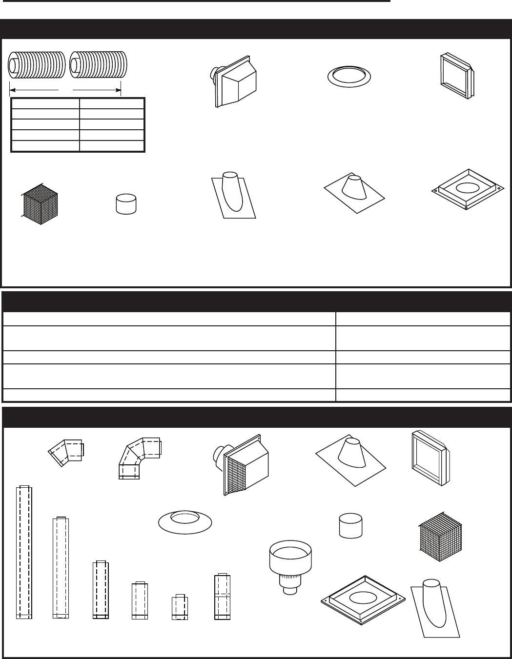
A
T199
Flex vent components
12/9/03
Vent Kit A
GFP74FV3 3’ (914 mm)
GFP74FV10 10’ (3 m)
GFP74FV20 20’ (6 m)
GFP74FV30 30’ (9 m)
HFTK
Horizontal Flex
Terminal Kit
(76478)
SC7
Storm Collar
(Used with 7” dia.
pipe system only)
(760505)
VEF
Vinyl Extension
Frame Kit
(For use with HFTK)
GFP7FS
Firestop Spacer
RF705
Roof Flashing
(0/12 to 5/12)
(Used with 7” dia. pipe
system only)
(76048)
RF7612
Roof Flashing
(6/12 to 12/12)
(Used with 7” dia.
pipe system only)
(76049)
AS7-8
Attic Insulation
Shield (76093)
HTG
Horizontal Terminal
Guard Kit
(75783)
Flexible Venting Individual System Components
Temco Flex Vent Termination Kits Available
Square Horizontal Cap (uses 7/4 Flex) HFTK
Round Hor. Term. Cap (High Wind)
(Includes 7/4 Flex x 3 ft. long) CDV-HSK
Round Hor. Term. Cap (uses 7/4 Flex) RN47
Vertical Vent Kit
(Includes 7/4 flex x 10 ft. long, Firestop Thimble Assy) VSK7MH-2
Vertical Vent Kit (uses 7/4 Flex) VSK7
T199
T204
TDV
venting components
12/03
TDV Series Direct-Vent System Installation
TDV45S
Elbow TDV90
Elbow HSQ47
Horizontal Vent terminal
(Includes Wall thiumble)
(75915)
SC7
Storm Collar
(76050)
RF705
Roof Flashing
0/12 to 5/12
(76048)
VEF Vinyl
Extension
Frame for
use with
HSQ47
AS7-8
Attic Insula-
tion Shield
(76093)
HTG
Horizontal
Terminal
Guard Kit
(75783)
RF7612
Roof Flash-
ing
(6/12 to
12/12)
(76049)
FS7
Firestop Spacer
(7604)
VT47
Vertical Vent
Terminal
(75909)
TDV48 TDV36 TDV18 TDV12 TDV5 TDV1218
Adjustable
Vent T204
NOTE: Flexible and rigid vent system components are NOT interchangeable unless otherwise specified in the venting
instructions.
20
Temco DV5200 Series
78674
Operating Instructions
Only glass approved by CFM Corporation
should be used on this fireplace.
• The use of any non-approved replace-
ment glass will void all product warranties.
• Care must be taken to avoid breakage of the glass.
• Do not operate appliance with glass front re-
moved, cracked or broken.
• Replacement glass (complete with gasket) is
available through your Temco dealer and should
only be installed by a licensed qualified service
person.
• Do not remove the glass door when unit is hot to
the touch.
• NOTE: Inspect the door gasket. The braided door
seal gasket has a small overlap area near corner of
the top black extrusion. Identify this area and install
the door with this area at the top.
Glass Door Removal Procedure
1. Remove upper and lower louvre assemblies and set
aside. Refer to louvre installation instructions.
2. Using gloves, carefully unlatch the latches (3) along
the bottom edge of the glass door. Then as the top
latches are unlatched, continue to place gentle pres-
sure to the glass door to reduce the chances of the
door being dropped accidentally.
3. Once all latches have been secured, pull the door
(4) outward from the face of the fire chamber.
4. Take care during handling and cleaning of the glass
door so that it is not dropped or accidentally broken.
5. Cleaning of the glass should only be done when the
glass door is cool. Refer to Glass Cleaning section.
6. To reinstall glass door, carefully center the door
onto the face of the fireplace (left to right), sec-
ond, shift the door assembly upwards slightly, then
secure door with the throw-over latches above and
below the firechamber. By shifting the door upwards
before latching, the upper door latches will be less
visible once the upper louvre is installed.
7. Reinstall the upper and lower louvre assemblies.
Refer to louvre installation.
Glass Cleaning
It will be necessary to clean the glass periodically. Dur-
ing start-up, condensation - which is normal - forms on
the inside of the glass and causes dust, lint, etc. to cling
to the glass surface. Also, initial paint curing can de-
posit a slight film on the glass. In some geographic ar-
eas, a white film may be deposited on the glass due to
combustion of some of the constituents of natural gas.
It is therefore recommended that initially the glass be
cleaned two or three times with non-abrasive common
household cleansers and warm water. After that, the
glass should be cleaned two or three times a season
depending on the amount that the fireplace is used.
To remove, simply unlatch the top and bottom door
latches and carefully pull door forward. Use of gloves
recommended.
Do not clean when the glass is hot.
Do not strike or abuse glass.
Do not place glass door on edge after
removal.
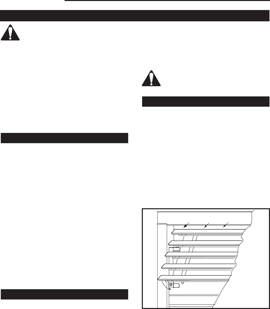
Louvre Installation
The fireplace is shipped without the louvre assemblies
installed. Various styles and finishes are available as
options. Contact your nearest Temco dealer/distributor
for information on the Louvre Kits available.
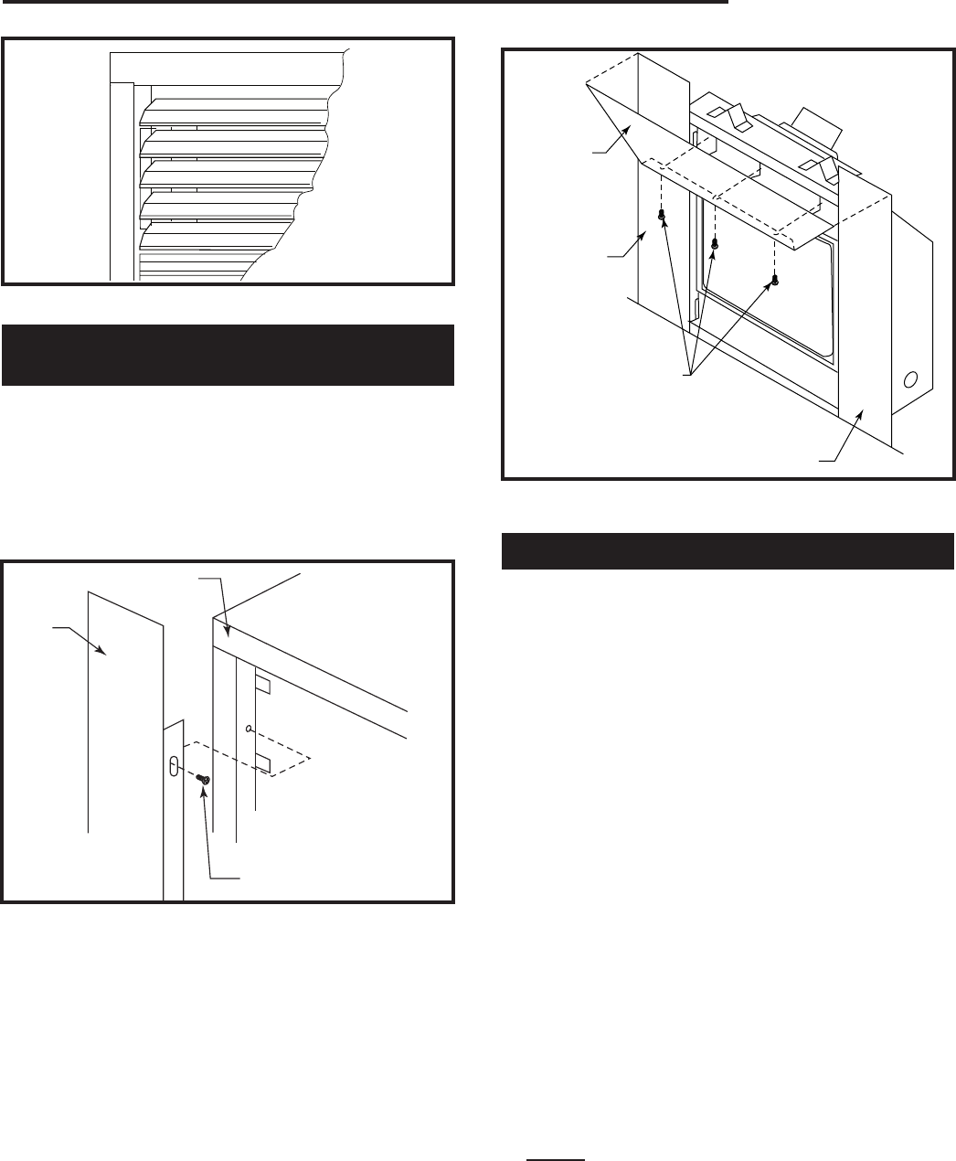
1. To install the upper louvre assembly, the second lou-
vre blade from the top on each louvre assembly will
hook onto the top tabs of the louvre brackets. (Fig.
29)
2. Once the second louvre blade has engaged the top
tab of the end brackets, swing the bottom of the lou-
vre assembly inward so the louvre hangs flush with
the fireplace face.
3. To install the bottom louvre assembly, hook the top
louvre blade ends over the top hang tabs located at
the left and right ends of the panel opening.
T201
Louvre install
12/10/03
T201
Fig. 29 Hook second louvre blade onto top tabs of louvre
brackets.
21
Temco DV5200 Series
78674
T202
Louvre in place
12/10/03 djt
T202
Fig. 30 Louvre in place.
Optional Extended Face Panel Kit
Installation
Model 36SB
1. Place side panel as shown in Figure 31.
2. Install screws at tab locations to install side exten-
sion panels. NOTE: If pilot holes are not provided
in the fireplace, mark and drill 3/32” diameter pilot
holes using the slotted tabs in the side extension
panels as a guide.
Side
Panel
Fireplace
Screw (Provided)
Fig. 31 Place side panel and secure with three (3) screws.
FP1825
3. Place top surround panel over the side surround
extension panels. Center left to right, then secure
with three (3) screws provided. Screw pilot holes
are located at the inside top opening of the fireplace
directly above the top. (Fig. 32)
Top Face
Panel
Side Panel
Screws
(Provided)
Side Panel
FP1826
Fig. 32 Place top panel over side panels and secure with
three (3) screws.
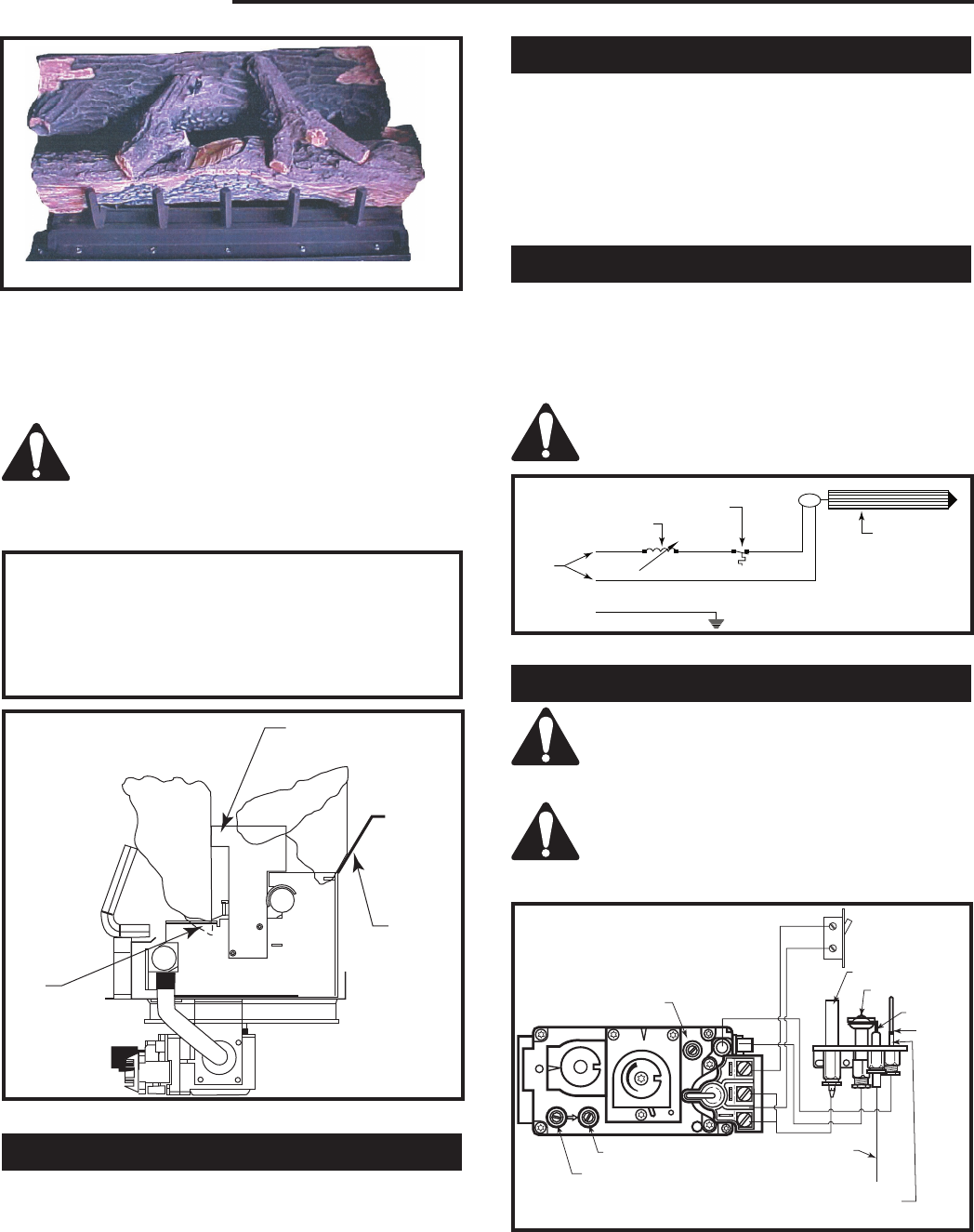
Log Installation
Attention: Glass door should be removed when install-
ing logset and prior to lighting the unit.
1. Remove glass door (Refer to “Glass Door Removal
Procedure”)
2. Remove logs from carton and inspect.
3. Rear log should be installed onto rear log supports.
Match up slots on rear of log with the vertical log
bracket tabs.
4. The front log should be placed on the center log sup-
ports, slots aligned with tabs, and log placed rear-
ward.
5. Top twigs can then be placed in their designated po-
sitions provided with pins on back logs, and grooves
on the center log. (Fig. 33)
6. Unpack steel wool and cut off a 1” x 3” (25 x 76 mm)
strip. Save the remainder of the steel wool for future
use. Carefully stretch the strip out the full length of
the burner’s ported area and then place it on the
ember tray allowing the steel wool to hang over the
burner. Place the rock wool loosely on top of the
steel wool and top edge of the ember retainer along
entire length of ported area of front burner. Use indi-
vidual pieces of rock wool about the size of quarter.
Rock wool should be fluffed up and not compressed.
Rock wool must be held up by ember retainer tray.
Do not allow embers to fall on burner and cover
burner ports.
7. Ember tray ends beyond burner port area and area
in front of grate may be covered with lava rock to suit
individual appearance preferences.
22
Temco DV5200 Series
78674
Electrical Services
All fan kits are equipped with a 120V, 60Hz blower, less
than 12 amps.
NOTE: All electric connections are to be made in ac-
cordance with CSA Standard C22.1 - Canadian Electri-
cal Code part 1 or with the National Electrical Code,
ANSI/NFPA 70 (latest addition) and/or in accordance
with local codes.
Speed Control Switch
1. The blower combination on/off switch and electronic
speed control is supplied loose to allow mounting in
a conveniently located wall mounted electrical box.
2. Wire speed control into black (hot) side of 120V,
60Hz line as shown in blower wiring diagram.
CAUTION: Should this fan require servic-
ing, the power supply must be discon-
nected.
TL131
Fig. 33 Correct log placement for the DV52MBN.
Bracket
Log
Support
Slot
TL132
Fig. 34 DV5200 log placement side view.
M
White
Black
T173
blower wiring
11/14/03 djt
GGreen
120
Volt
Speed Control
Switch
Temperature
Sensor
Fan
T173
Fig. 35 Fan wiring diagram.
FP387
SIT Valve and pilot
H
I
L
O
O
F
F
O
N
O
F
F
P
I
L
O
T
O
F
F
EA
P
I
L
O
T
THTP TP TH
Pilot Screw
Wall Switch
(not supplied)
Thermopile
Pilot
Ignitor
To Piezo
Thermocouple
Manifold Pressure
Supply Pressure
IN OUT
FP387
Fig. 36 Pilot and valve wiring.
8. Purge lines and test pilot operation.
9. Replace glass door. The door must be installed be-
fore operating the fireplace. (Refer to Page 20)
10. Flame should not impinge (touch) on logs.
WARNING: Do not place rock wool, lava rock
or any other materials on the burner. Use only
certified material supplied with this fireplace.
Using non-certified materials will void the war-
ranty.
The embers supplied with your fireplace are
made from a high grade rock wool and should
be handled carefully. Wash your hands imme-
diately after touching to avoid irritation. The
embers must be placed correctly in order to
function properly.
Thermostatic Fan Kit
(Kit # GDVTFK)
Millivolt System
CAUTION: At installation and/or after any
service work or repairs glass door must be
removed before proceeding to lighting instruc-
tions.
CAUTION: At installation and/or after any
service work or repairs glass door must be
removed before proceeding to lighting instruc-
tions.
23
Temco DV5200 Series
78674
Recommended Maximum Lead Length
(Double Wire)
When Using Wall Switch or Thermostat
Wire Size Max. Length
14 ga. 50’ (15.2 m)
16 ga. 32’ (9.8 m)
18 ga. 20’ (6 m)
20 ga. 15’ (4.6 m)
22 ga. 10’ (3 m)
NOTE: Some Models are supplied with 15’ (4.6 m) of
double wire for use with a wall switch.
CAUTION: Do not wire 120V power to millivolt
switches or thermostats.
Managing Heat Output
The heat output from the appliance may be controlled
by adjusting the main gas valve. Reference lighting
instructions on Page 24 and chart on Page 33 showing
inputs at all the settings.
The main gas valve may be adjusted anywhere be-
tween high and low to give the desired combination of
flame aesthetics and heat output.
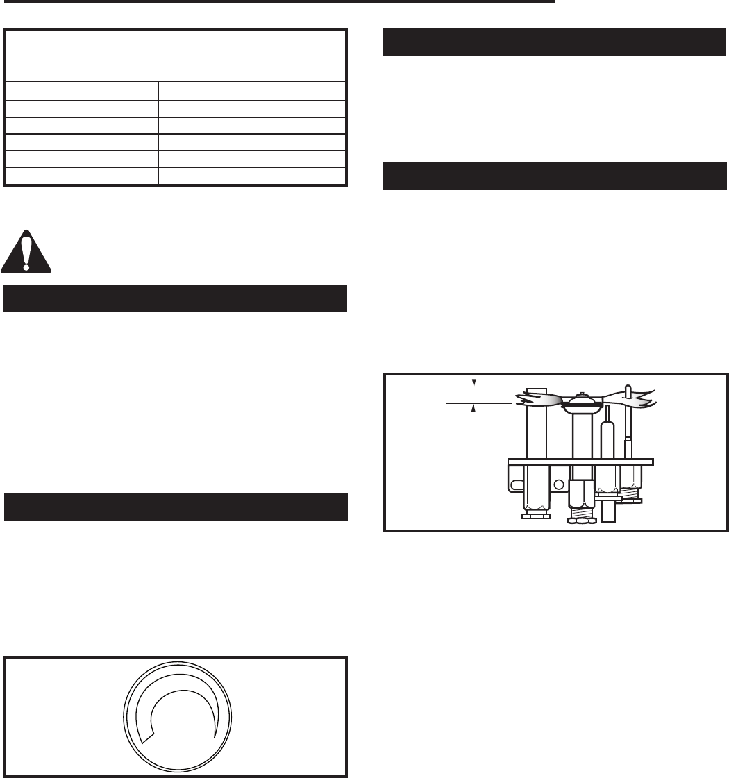
HI
LO
T155
PS24
hi/lo knob
11/10/03 djt
Turn knob clockwise
to increase flame
Turn knob
counterclockwise
to decrease flame
Fig. 37 Flame adjustment knob.
Fan Operation
The fan operates automatically - turn the knob on the
speed control to adjust to the desired speed. The fan
will turn on as the fireplace comes up to operating tem-
perature. After the unit has been turned off and the unit
cooled to below a useful heat output range the fan will
shut off automatically.
Flame Characteristics
It is important to periodically perform a visual check of
the pilot and burner flames. Compare them to Figure
38.
If the flame patterns appear abnormal, contact a quali-
fied service provider for service and adjustment.
Pilot Burner Adjustment
1. Adjust pilot screw to provide proper sized flame.
2. Leak test.
F584-703
Honeywell
& PSE
pilot flames
3/8” - 1/2”
(10 - 13 mm)
F584-703
Fig. 38 Correct flame appearance.
Burner On/Off Control
All models may be used with an optional wall switch
that turns the main burner on or off. Optional millivolt
thermostats (GFPMT) and remote control may be sub-
stituted for the wall switch (For installation of these op-
tions, detail instructions are provided with optional kits).
CAUTION: If the remote receiver is located in the gas
control area (under the firebox), clearance should be
below the firebox at least 2” (51 mm) to avoid high tem-
peratures (receiver should not be exposed to tempera-
tures exceeding 130°F).
24
Temco DV5200 Series
78674
Lighting and Operating Instructions
FOR YOUR SAFETY READ BEFORE LIGHTING
WARNING: If you do not follow these instructions exactly, a fire or explosion may result caus-
ing property damage, personal injury or loss of life.
Before Lighting
A. Smell all around the appliance area for gas. Be
sure to smell next to the floor because some gas is
heavier than air and will settle on the floor.
WHAT TO DO IF YOU SMELL GAS
• Do not try to light any appliance
• Do not touch any electrical switch; do not use any
phone in your building.
• Immediately call your gas supplier from a neigh-
bor’s phone. Follow the gas supplier’s instructions.
• If you cannot reach your gas supplier, call the fire
department.
B. Use only your hand to push or turn the gas control
knob. Never use tools. If the knob will not push in
or turn by hand, do not try to repair it. Call a service
technician. Force or attempted repair may result in
a fire or explosion.
C. Do not use this appliance if any part has been un-
der water. Immediately call a qualified technician to
inspect the appliance and to replace any part of the
control system which has been under water.
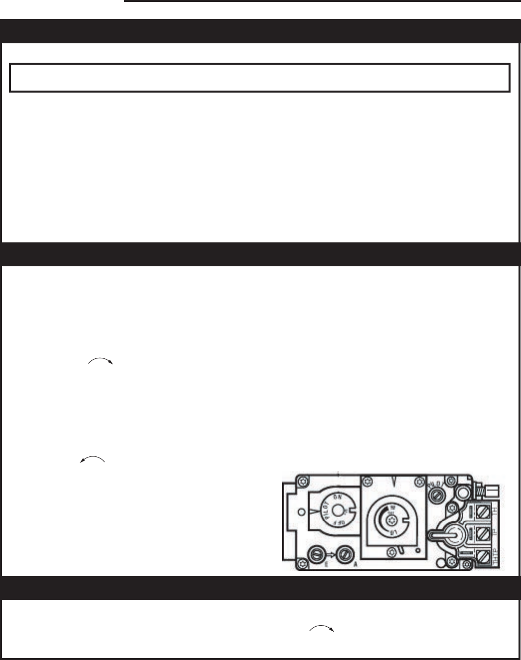
Lighting Instructions
1. Stop! Read the safety information above.
2. Turn off all electrical power to the appliance.
3. Open the access door located at the bottom of the
appliance to expose the controls.
4. If the control knob is not already in the “OFF” posi-
tion, then push in the gas control knob slightly and
turn clockwise to “OFF”. NOTE: The knob
cannot be turned from “PILOT” to “OFF” unless
the knob is pushed in slightly. Do not use force.
5. Wait five (5) minutes to clear out any gas. If you
smell gas, STOP! Follow “B” in safety information
above. If you do not smell gas, then go on to the
next step.
6. Push in the control knob slightly and turn it coun-
terclockwise to the “PILOT” position.
7. Push in the control knob all the way and hold it.
With the other hand, push in the red indicator but-
ton until you hear a click. Now observe closely the
pilot burner located on the rear right hand side of
the main burner. If a flame has appeared, ten con-
tinue to depress the control knob for 20 seconds. If
the flame did not appear, then continue to depress
the red indicator button every 5 seconds until a
flame is established. NOTE: If after 30 seconds a
flame has not yet been established, then turn the
control knob back to the “OFF” position and repeat
Steps 7 and 8.
8. Once the pilot flame has been established, hold
the control knob in the depressed position approxi-
mately 20 seconds before releasing. If the flame
goes out, repeat Steps 7 and 8.
9. Now turn the control knob to the “ON” position.
The burner will not light unless the wall switch,
thermostat, or remote control is turned on or, in the
case of a thermostat, there is a call for heat.
10. Close the access door and turn all electric power
back to the appliance.
Turn Off the Appliance
1. Turn off all electrical power to the appliance if
service is to be performed.
2. Open the control access door.
3. Push in the gas control knob slightly and turn clock-
wise to the “OFF” position. DO NOT FORCE!
4. Close the control access door.
25
Temco DV5200 Series
78674
Troubleshooting
SIT Millivolt Valve
NOTE: Before troubleshooting the gas control system, be sure external shut off is in the “ON” position.
WARNING: Before doing any gas control service work, remove glass front!
Table 1
Valve Type Main Operator Safety Magnet
NOVA MV Plus Minimum Voltage 145mV Hold-in Current Less than 285mA
Coil Resistance 2.25Ω ± 0.5Ω Drop-out Current Greater than 125mA
Coil Resistance 0.108Ω ± 0.003Ω
Problem Possible Cause Solution
Unit fails to operate Batteries weak in remote unit Replace batteries in both receiver and hand held
control
Pilot will not light. Air in gas lines. Bleed all air from gas lines.
Defective spill switch Check for continuity across spill switch leads. Re-
place spill switch if excessive resistance is present,
or if circuit is electrically open.
Wrong inlet pressure. With the main burner functioning, adjust the inlet
pressure regulator to supply gas to the appliance
within the design parameters of the appliance manu-
facturer. (Typically 7”NG, 11”LPG).
Defective spark electrode. Replace piezo wire if insulation is cracked or the tip
is corroded.
Verify that the spark gap between the pilot and the
electrode is correct.
Defective piezo wire. Replace piezo wire if insulation is damaged, or the
wire is broken or corroded.
Safety interlock function Allow thermocouple to cool until the mv drops below
engaged. the hold-in requirements of the safety magnet, (30
seconds or less). Re-light pilot.
Pilot will not hold. Wrong inlet pressure. With the main burner functioning, adjust the inlet
pressure regulator to supply gas to the appliance
within design parameters of the appliance manufac
turer. (Typically 7”NG, 11”LPG)
Pilot adjustment screw not After the pilot has been lit for approximately three
properly adjusted. minutes, and only the thermo-generator wire con-
nected to the main operator head, measure the volt-
age across TPTH and TP. This open circuit volt
age should be between 500mv and 750mv. Tune
the pilot adjustment screw until the mv reading
falls within these parameters. (Counter-clockwise
increases mv reading, clockwise decreases).
Thermocouple or Make certain that the thermocouple and thermo-
thermo-generator not generator are fully inserted and tightened into their
properly inserted into the pilot receptacles in the pilot head. The thermocouple
housing should be threaded into the valve hand-tight, plus
1/4 turn with wrench.
System Checks
26
Temco DV5200 Series
78674
Pilot will not hold Thermocouple or With the thermocouple and thermo-generator tips
thermo-generator has film cool, clean the upper 3/8” with a very fine emery
continued... build-up on tip. cloth.
Electrical resistance too high. Using a very fine emery cloth, clean thermo-genera-
tor and thermocouple connections at valve. Tighten
thermocouple into valve hand-tight, plus 1/4 turn
with a wrench.
Defective thermocouple. Verify that thermocouple is not kinked or damaged.
(mv Plus systems) Check open circuit voltage of thermocouple. Voltage
should be between 18mv and 28mv. If voltage is
less than 14mv, replace thermocouple.
Defective thermo-generator. After the pilot has been lit for approximately three
(Millivolt system) minutes, and only the thermo-generator wire con-
nected to the main operator head, measure the volt-
age across TPTH and TP. This open circuit voltage
should be between 500mv and 750mv. Tune the
pilot adjustment screw until the mv reading falls
within these parameters. (Counter-clockwise
increases mv reading, clockwise decreases)
Defective safety magnet. Verify operation of safety magnet in the following
(mv Plus systems) manner.
(A) Depress and hold pilot button.
(B) Verify open-circuit thermocouple voltage as de-
scribed in previous step.
(C) Reconnect thermocouple to valve.
(D) Measure the Millivoltage between the solder
button on the base of the safety magnet, and the
valve body. If the mv reading is above 6mv for
vented appliances, or 8.5 mv for un-vented
appliances, and the safety magnet does not hold,
replace the valve.
(E) If closed circuit mv reading is the same as the
open circuit reading, the coil is electrically open.
Replace the valve.
Defective Safety Magnet Verify operation of safety magnet in the following
(Millivolt system) manner.
(A) Remove all wires from the terminals of the main
operator.
(B) Measure the electrical voltage between the term-
inals TPTH and TP. If the voltage is above 110mV
and the safety magnet does not hold, replace the
valve.
Pilot orifice blocked. Replace orifice with a new orifice of the exact size
and type.
Pilot drops out. Wrong pilot orifice. Replace the orifice with a new orifice supplied
specifically for the appliance and gas type in
question.
No gas to main burner Low gas pressure to appliance. With the main burner functioning, adjust the inlet
pressure regulator to supply gas to the appliance
within the design parameters of the appliance manu-
facturer. (Typically 7”NG, 11”LPG).
Problem Possible Cause Solution
System Checks (continued)
27
Temco DV5200 Series
78674
Problem Possible Cause Solution
System Checks (continued)
Pilot not lit. Light pilot and wait for thermo-generator to heat up
sufficiently to power the main operator. If pilot fails
to light, or hold, refer to above sections.
Control knob not in ON Rotate OFF/PILOT/ON control knob to the ON posi-
position. tion.
Thermostat/wall switch Thermostat not in ON position. Turn thermostat ON, and adjust temperature control
will not cycle main to call for heat.
burner.
Thermo-generator output After the pilot has been lit for approximately three
voltage not within design minutes, and only the thermo-generator wire con-
parameters. nected to the main operator head, measure the
voltage acrossTPTH and TP. This open circuit volt-
age should be between 500mv and 750mv. Tune the
pilot adjustment screw until the mv reding falls with-
in these parameters. (Counterclockwise increases
mv reading, clockwise decreases) If unable to meet
minimum requirements, repalce thermo-generator.
Defective thermostat or (A) With the pilot adjusted properly, ( After the pilot
thermostat wiring has been lit for approximately three minutes, and
only the thermo-generator wire connected to the
main operator head, measure the voltage across
TPTH and TP. This open circuit voltage should be
between 500mv and 750mv. Tune the pilot adjust-
ment screw until the mv reading falls within these
parameters. Counterclockwise increases mv read-
ing, clockwise decreases), place a jumper wire be-
tween TPTH and TH. Take a mv reading across the
TPTH and TP terminals on the valve. This closed
circuit voltage should not fall below 300mv. Record
reading.
(B) Remove jumper wire form the TPTH and TH
connections, and reconnect the thermostat wires to
the same terminals. Take the closed circuit voltage
as described in the previous step. If the mv reading
drops below 150mvm, excessive resistance exists
in the thermostat circuit, and must be isolated and
eliminated.
Thermostat/wall switch Defective wall switch. Repeat the above troubleshooting items covered
will not cycle mian under “Defective thermostat or thermostat wiring”,
burner. except substitute the words “wall switch” where the
word “thermostat” appears in the instructions.
Excessive wire resistance. Make certain that all mv connections are made us-
ing wire of the proper size. (Reference Page 23).
Valve wired wrong. Thermo-generator leads must be connected to the
TPTH and TP connections of the main operator.
Thermostat wires must be connected to the TPTH ,
and TH terminals of the valve.
28
Temco DV5200 Series
78674
Problem Possible Cause Solution
System Checks (continued)
Main burner lights in Main operator coil defective. Verify electrical resistance of main operator coil in
the PILOT position. the following manner.
(A) Remove all wires from operator head.
With an Ohm meter, measure electrical resistance
between TP and TH terminals. If the resistance
does not fall within specification, replace valve.
(See table 1).
Debris on seat of main valve. Replace valve.
Main seat blown out as a Replace valve.
result of exposing LPG gas
valve to unregulated line
pressure in excess of 15 PSI.
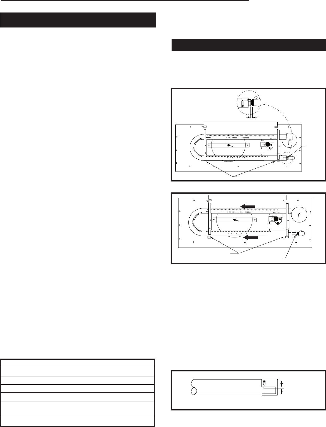
29
Temco DV5200 Series
78674
Fuel Conversion
WARNING: This Hi/Lo conversion kit must ONLY be
applied as part of a conversion kit supplied by the
appliance manufacturer for the specific appliance
and type of gas being converted.
The conversion shall be carried out in accordance
with the requirements of the provincial authori-
ties having jurisdiction and in accordance with the
requirements of the CSA B149.2 installation code
(Canada) and with the requirements of the Na-
tional Fuel Gas Code ANSI Z223.1/NFPA 54 (United
States).
WARNING: This conversion kit shall be installed
by a qualified service agency in accordance with
the manufacturer’s instructions and all applicable
codes and requirements of the authority having
jurisdiction. If the information in this instruction is
not followed exactly, a fire, explosion or production
of carbon monoxide may result causing property
damage, personal injury or loss of life. The qualified
service agency is responsible for the proper instal-
lation of this kit. The installation is not proper and
complete until the operation of the converted appli-
ance is checked as specified in the manufacturer’s
instructions supplied with the kit.
Installer Notice: Using an ink pen, fill out the re-
quired information on the conversion label. Remove
the backing from the label and stick the label in a
visible position on the bottom of the fireplace close
to the gas valve.
Installer Notice: These instructions must be left
with the appliance.
Instructions for converting your fireplace from Natural
gas to Propane/LP gas.
All fireplaces are shipped from the factory equipped to
operate on Natural gas. To convert the fireplace to op-
erate on Propane/LP gas, follow the instructions below.
Please see the appropriate parts list for your model for
parts included with the fireplace.
Check the items in the kit with the parts list. Notify the
supplier of any items that are missing before installing
the conversion kit.
T205
Dv burner
fuel conversion
1/8/04 djt
1/8” When Gas Tight
Burner
Orifice
Holding Tabs T205
Fig. 39 Bend holding tabs down and forward.
T206
Dv burner
bend tabs
1/8/04 djt
Bend Down Tabs Remove Burner Orifice T206
Fig. 40 Move burner tube to replace orifice.
1. Turn off the gas supply.
2. Turn off the electrical supply to the appliance if so
equipped.
To Replace Burner Orifice
1. Remove lava rock to expose screws and remove
grate assembly.
2. Use screwdriver and bend holding tabs down and
forward. (Fig. 39 & 40)
T207
air shutter
setting
1/8/04 djt
7/16” (11 mm)
T207
Fig. 41 Air shutter settings for propane/LP gas.
Conversion Parts Inluded with Fireplace
Description Part Number
Orifice 1.45 mm (Main Burner)-LP PCOA070H37
Label, Conversion 77740
Pilot, Orifice - LP 76263
Conversion Pressure
Regulator Assy - LP 74655
Label SIT Valve --
3. Move the burner to the left and off the burner orifice.
(Fig. 40)
4. Using a suitable tool, replace natural orifice #44 with
propane orifice 1.45 mm furnished with conversion
kit. Tighten orifice with suitable tool until gas tight.
(Fig. 39)
5. Move burner back to original position tight to orifice
and bend tabs back up.
6. Set the air shutter opening for the corresponding
gas used. (Fig. 41 and Chart on Page 33)
7. Replace grate assembly.
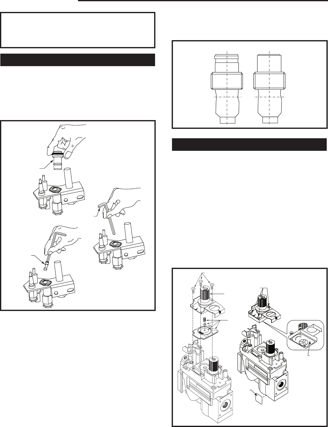
30
Temco DV5200 Series
78674
WARNING: Failure to position the parts in accor-
dance with these diagrams or failure to use only
parts specifically approved with this heater may
result in property damage or personal injury.
Replace Pilot Orifice
1. The pilot hood is held in place by spring pressure.
Remove the hood by pulling it directly up from the
pilot bracket. (Fig. 42)
2. Insert a 3/32” (4 mm) Allen wrench into the hexago-
nal keyway of the injector and rotate it counterclock-
wise until it is free of the injector journal. (Fig. 42)
T207
remove pilot hood
1/8/04 djt
Pilot Hood
Allen
Wrench
Conversion
Pilot
T207
Fig. 42 Remove pilot hood and orifice. Insert conversion
orifice.
3. Verify the new injector is proper for the applica-
tion. The injector size is stamped on the side of the
injector near the top. LPG injectors have a groove
machined around their circumference near the top,
while the NG injectors do not have a groove. (Fig.
43) Install the conversion orifice furnished with unit
(Conversion Kit).
4. Insert the Allen wrench into the end of the injector.
Insert the injector into injector journal, and rotate
the injector clockwise until a torque of 9 in/lbs. Is
achieved. Replace the pilot hood by aligning the tab
n the base of the hood with the slot in the side of the
pilot journal. Push the hood down, directly onto the
pilot bracket. (Fig. 43) The hood must sit squarely on
the bracket for proper operation. Check to insure the
hood is properly seated onto the pilot bracket.
T208
conversion
injectors
1/8/04 djt
LPG NG
T208
Fig. 43 Injectors.
Convert Valve to LP
1. Using a Torx T20 bit or slotted screwdriver, remove
and discard the three (3) pressure regulator mount-
ing screws (A), pressure regulator tower (B) and
diaphragm (C). (Fig. 44)
2. Insure the rubber gasket (D) is properly positioned
and install the new HI/LO pressure regulator assem-
bly to the valve using the new screws (E) supplied
with the kit. Tighten screws securely. (Fig. 44)
3. Install the enclosed installation label (F) to the valve
body where it can easily be seen.
4. Apply gas to system and relight appliance according
to manufacturer’s instructions.
5. With the main burner “ON”, test the new pressure
regulator assembly for leaks using a soap solution.
FC107
SIT820
valve conversion
10/03
A
B
C
O
F
F
P
I
L
O
T
O
N
D
E
F
FC108
SIT
regulator
conversion
10/03
O
F
F
P
I
L
O
T
O
N
FC1007/108
Fig. 44 Remove mounting screws, pressure regulator tower
and diaphragm assebly, discard. Replace regulator.
31
Temco DV5200 Series
78674
6. Relight the main burner in both the HI and LO posi-
tions, and verify proper burner ignition and opera-
tion.
7. Check inlet and manifold pressures. Loosen screw
in test port 1/2 turn to measure pressure. Tighten
screw when measurement is complete.
Pressure ranges are:
Gas Supply Pressure (inches w.c.)
Minimum Normal Maximum
LP (Propane) 10.8 11.0 14.0
Manifold Pressure (inches w.c.)
Normal (Hi) Normal (Low)
LP (Propane) 10.0” 6.3”
Manifold pressure can be measured by using a 5/16”
I.D. hose in the right hand side of the valve and con-
necting a manometer. Two test gauge ports are acces-
sible for test gauge connection:
1. Tap on the left side of the valve will give inlet supply
pressure.
2. Tap on the right side of the valve will give manifold
pressure.
Min. Input Max. Input
DV5200MBP 17,500 25,000
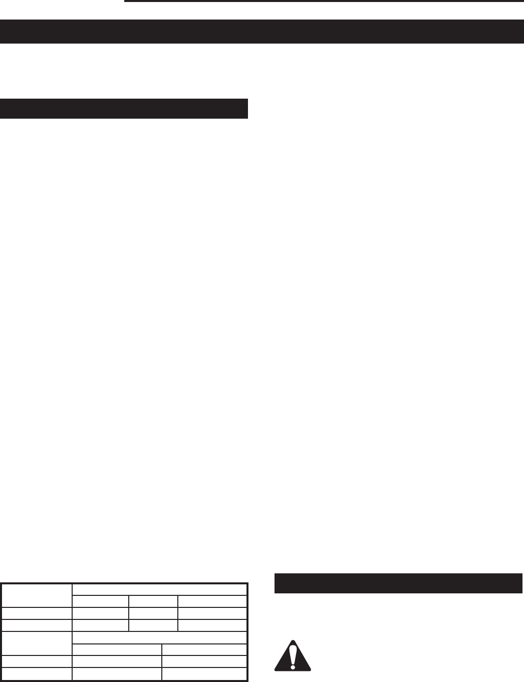
32
Temco DV5200 Series
78674
Maintenance
Once installed, the unit should be operated at least
three (3) times to ensure that all is in working order.
NOTE: Manufacturing oils will smoke during initial firing
of appliance. Open windows for ventilation.
Unit Adjustment
Before leaving, the installer should make the following
checks:
Btu Input/Gas Pressure
The fireplace input is marked on the Rating Plate. The
gas inlet pressure specified in Table 1 is the pressure
where the field-installed gas line connects to the gas
control. This is measured at the inlet test port on the
gas valve in the appliance. Ensure that pressure is as
shown in Table 1.
The manifold pressure is controlled by a regulator
built into the gas control and should be checked at the
pressure outlet test port located on the body of the gas
valve.
The pressure should be checked with the appliance
burning on high (highest setting) and all other gas ap-
pliances turned on. One must then read the manometer
and if pressures are not as specified in Table 1, then the
inlet pressure must be adjusted.
The appliance and its individual shut-off valve must be
disconnected from the gas supply piping system during
any pressure testing of the system at test pressures in
excess of 1/2 psig (3.5 KPa).
Manifold pressure can be measured by using a 5/16”
I.D. hose or tubing. Using a small blade screwdriver,
back out the pressure screw for one full turn. Next, slip
the tubing over the pressure tap extension to check
the pressure with a manometer. Inlet and outlet pres-
sure taps are located on the front (lower left side) of the
valve body.
1. Tap on the left side of the valve will give inlet supply
pressure.
2. Tap on the right side of the valve will give manifold
pressure.
Pressure ranges are as listed below:
Table 1
Gas Supply Pressure (inches w.c.)
Minimum Normal Maximum
Natural Gas 4.5” 7.0” 14.0”
LP (Propane) 10.8” 11.0” 14.0”
Manifold Pressure (inches w.c.)
Normal (HI) Normal (Low)
Natural Gas 3.5” 1.6”
LP (Propane) 10.0” 6.3”
High Altitude
When installing this fireplace at an elevation between
0 and 2000 feet (0 - 610m) in the USA and 0 and 4500
feet (0 - 1370m) in Canada the input rating does not
need to be reduced.
When installing this fireplace at an elevation above
2,000 feet (in the United States), it may be necessary to
decrease the input rating by changing the existing burn-
er orifice to a smaller size. Input should be reduced
four percent (4%) for each 1,000 feet above sea level,
unless the heating value of the gas has been reduced,
in which case this general rule will not apply. To identify
the proper orifice size, check with the local gas utility.
When installing this fireplace at an elevation above
4,500 feet (in Canada), check with local authorities.
Consult your local gas utility for assistance in determin-
ing the proper orifice for your location.
Main Burner/Pilot
The pilot flame size is factory set. The pilot flame
should be at least 1¹⁄₂” (38 mm) long. The flame should
be impinging on the pilot generator. Pilot size can be
adjusted through the pilot adjust screw. If the pilot flame
is too small and can not be adjusted through the pilot
adjust screw then there is the possibility of dirt in the
pilot orifice in which case the pilot orifice should be
cleaned or replaced.
The main burner should be allowed to operate for 15 to
20 minutes before making any adjustment to the burner.
The air shutter on the right front of the main burner
should be adjusted so that there are no orange/red
flames with dark sooty looking tips. A luminous yellow
flame with blue base is what is acceptable.
For burner air shutter settings see Air Shutter Settings
chart. (Page 33)
If there is too much primary air then the flame will be
very blue with yellow tips and smaller flame height.
If there is too little primary air then the flame will be yel-
low with orange/red tips on the back flames with dark
sooty elongated tips. In this condition the glass and logs
could show signs of soot accumulation within 10 to 20
minutes.
Maintenance
Motor and Blower for Fan Kit (optional)
This motor has been factory oiled and under normal
operating conditions should not require oiling.
WARNING: Ensure the power is turned off to
the fireplace before servicing.
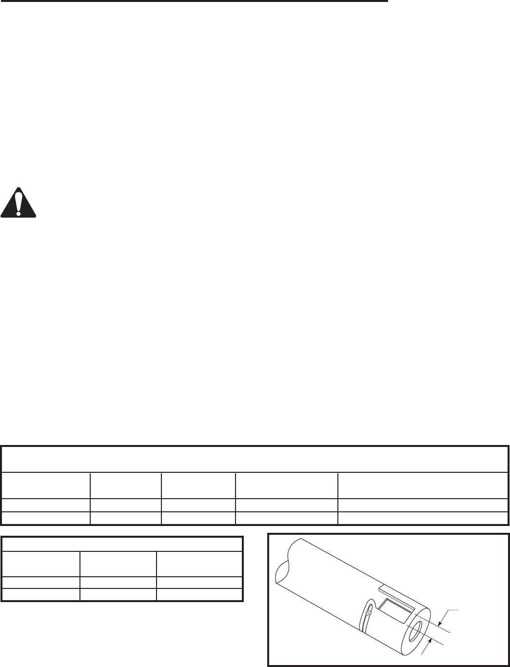
33
Temco DV5200 Series
78674
Cleaning
This unit should be cleaned and serviced by a Qualified
Gas Technician at least annually. More frequent clean-
ing may be necessary if pet hair accumulates, dust and
lint are present, or if the unit is located in a high traffic
area. A Qualified Agency is defined in the Gas Code.
Cleaning should include burner tubes, orifice/injectors
(refer to section B.3 National Fuel Gas Code), logs,
ceramic base, and pilot assembly. It is recommended
that the sediment trap in the gas line be emptied and
cleaned at this time. (See Section 3.7.2 National Fuel
Gas Code)
Burner, Pilot, Firebox and Logs
CAUTION: Before cleaning or moving logs or
other parts of the unit, be sure to read the sec-
tion on important safeguards.
Cleaning should be done before the logs are used each
year and after long periods of non-use. All cleaning
should be carried out when the appliance is cold.
Cleaning will be required under normal use. Dusting the
front grate or the control knob panel may be required
occasionally. Do not use any cleaning fluids to clean the
logs or any other part of the appliance.
If the flames show any unusual shapes or behavior, or if
the burners fail to ignite properly, then the burner holes
may require cleaning. If this occurs, contact your near-
est dealer to get the appliance serviced.
Alternatively, the appliance can be cleaned by removing
all the logs. Handle the logs gently so as not to damage
them. Always lift each log by holding it carefully at each
end.
After the logs are removed allowing access to the burn-
er area, use a vacuum cleaner to carefully remove dust
and loose particles from the base, logs and from around
the burners. Gloves are recommended to prevent the
ceramic fibers that compose the logs from pricking your
skin. If the skin is pricked, wash gently with soap and
water. Use extreme caution in cleaning around the pilot.
The pilot should not be moved or altered from the origi-
nal factory setting (Pilot to burner preset location). The
burner should be placed back into its original locked
and secure position after cleaning and servicing(proper
location of burners are critical). NOTE: All replacements
and repairs should be performed by a qualified techni-
cian (contact your nearest dealer). After cleaning and/or
repairs, follow instructions for positioning of logs as
illustrated on Page 21.
Glass
It will be necessary to clean the glass periodically. Dur-
ing startup it is normal for condensation to form on the
glass and cause dirt, lint, etc., to adhere to the inner
surface of the glass. There also will be a film deposited
on the glass during the initial use of the fireplace due
to initial curing of the paint. It is recommended that
the glass be cleaned with a non-abrasive household
cleaner and warm water. Be sure to rinse and dry the
glass well as not to leave any marks. It will be neces-
sary to clean the glass up to 3 times a season depend-
ing on use of the fireplace.
Louvres/Trim/Surround
All gold, platinum, black anodized and painted surfaces
should only be wiped off with a soft non-abrasive damp
cloth (a mild dish soap can be used if necessary).
DO NOT use brass or other metal polishes, glass clean-
ers or any abrasive cleaners as this will mark and dam-
age brass or painted surfaces.
Normal and High
Direct Vent Units - Inputs - Orifice Size - Altitude
BTU/Hr BTU/Hr Manifold Pressure Orifice 0 - 2000ft. Altitude in USA
Model Min. Input Max. Input @ Max. Orifice 0-4500ft Altitude in Canada
DV5200MBN 17,000 25,000 3.5”w.c. #44 DMS
DV5200MBP* 17,500 25,000 10.0” w.c. 1.45 mm
Air Shutter Settings
Opening Opening
Model “A” (inches) “A” (mm)
DV5200MBN 1/16” 1.6 mm
DV5200MBP* 7/16” 11.0 mm
NOTE: These are minimum settings. Air shutter open-
ings may be increased to prevent flame sooting.
T203
Air shutter
12/12/03 djt
Opening
“A”
T203
Fig. 45 Air shutter opening.
* NOTE: Model number after field conversion.
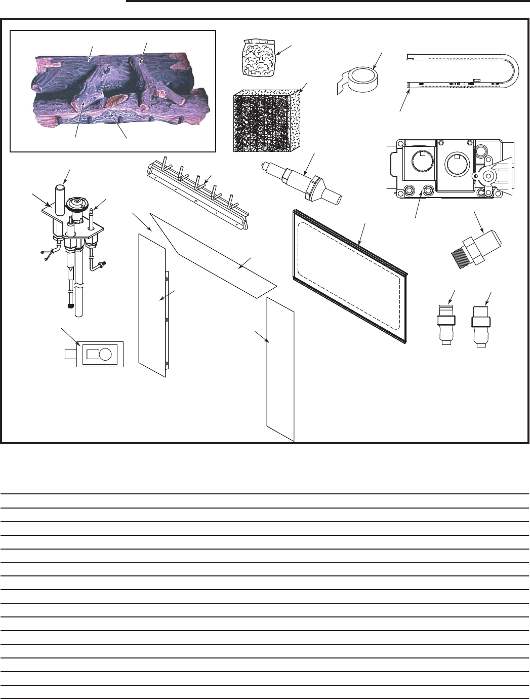
34
Temco DV5200 Series
78674
Ref. Description DV5200MB
1. Log Set 78369
1a. Log, Front 76895
1b. Log, Back 78016
1c. Log, Right Twig 75318
1d. Log, Left Twig 75319
2. Rock Wool (Bag) 76675
3. Stainless Steel Wool (3” x 3” x 3”) 77661
4. Gasket Tape 5/8” Wide 75448
5. Burner 77440
6a. Gas Valve SIT - LP 76448
6b. Gas Valve SIT - Natural 76449
7a. Burner Orifice - LP/Propane PCOA070H37
7b. Burner Orifice - Natural PCOA070H06
8. Piezo 65180
1 5200MB
1a
1b 1c
1d
3
4
6a,b
8
9a,b
13
12
15
2
5
16
10a
10b
7a,b
17
17a
17b
17c
CFM Corporation reserves the right to make changes in design, materials, specifications, prices and discontinue colors and products at any time,
without notice.
DV5200MB

35
Temco DV5200 Series
78674
DV5200MB (continued)
Always include correct name, part number, valve
manufacturer, model number and serial number of the
appliance when ordering service parts.
If you desire to communicate with the factory, write to
Customer Service at:
CFM Corporation
2695 Meadowvale Blvd.
Mississauga, Ontario
Canada L5N 8A3
Servicing
Repair and replacement work should only be done by a
qualified service person.
Always shut off the gas supply and make sure the appli-
ance is cool before beginning any service operation.
Always check for gas leaks after servicing.
9a. Pilot, SIT - Natural 76261
9b. Pilot, SIT - LP 76335
10a. Pilot Orifice - Natural 76262
10b. Pilot Orifice - LP 76263
11a. Rep. Reg. Assembly - LP Hi/Lo 82979 (not shown) 74655
11b. Rep. Reg. Assembly - Natural Hi/Lo 86354 (not shown) 74654
12. Thermocouple PCOA075
13. Thermopile (Pilot Generator) PCOB021
14. Glass Door Assembly 78054
15. Grate Assembly 76485
16. Door Switch 75520
17. Optional Extended Face Panels 76114 (36SB)
17a. Top Surround 76105
17b. Left Side Surround 76107
17c. Right Side Surround 76106
18. Black Anodized Aluminum Grille Panels (Optional) (not shown) GBL5200
19. Gold Colored Anodized Aluminum Grille Panels (Optional) (not shown) GPB5200
20. Platinum Colored Anodized Aluminum Grille Panels (Optional) (not shown) GPT5200
21. Black Painted Steel Grille Panels (Standard) (not shown) GST5200
Ref. Description DV5200MB

36
Temco DV5200 Series
78674
Limited Warranty
TEMCO Fireplace Products Direct Vent Gas Fireplaces
This warranty is limited to TEMCO Fireplace Products
Direct Vent Gas Fireplaces (henceforth, Product) manu-
factured by CFM Corporation (henceforth, CFM).
ONE YEAR WARRANTY
CFM warrants all components of the Product to be free
of defects in materials and workmanship for a period of
one year from the date of installation, with the exception
of the warranty on logs and ember base. If, by the sole
determination of CFM, any component covered under
this warranty is found to be defective, CFM will, at its
option, repair or replace the defective component at
no charge and will pay labor cost incurred as specified
in the current CFM Labor Allowance Schedule, 71313.
If CFM determines replacement or repair is not eco-
nomically practical, CFM will, at its option, refund the
purchase price of the Product. Date of installation and
purchase price must be verified by acceptable proof of
purchase.
This warranty covers only parts and labor as provided
above. In no case shall CFM be responsible for materi-
als, components or construction which are not manu-
factured or supplied by CFM, or the labor necessary to
install, repair or remove such materials, components or
construction.
NOTE: If allegedly defective components need to be
returned by CFM in connection with the above warran-
ties, frieght or postage charges must be prepaid.
QUALIFICATIONS
For the above warranties to apply:
The Product must be installed by a qualified in-
staller; strictly in accordance with CFM installation
instructions, and in compliance with local codes
and ordinances. The logs must be placed strictly in ac-
cordance with the arrangement described in the instal-
lation instructions.
The Product must be operated and maintained ac-
cording to the instructions furnished. Alteration of the
Product in any way is prohibited and voids any and
all warranties. Removal of the data plate alters the
Product and voids the warranty.
The installer must have completed the installation
and Startup Checklist, a copy of which must be
submitted along with proof of purchase, to obtain
prior approval for warranty repair or replacement
and to affect a warranty claim. The Checklist is
found on Pages 20 and 21 of this manual.
The limited warranty applies only to the original owner
of the Product or the original owner of the dwelling in
which the Product was installed. Use of any parts other
than genuine factory provided replacement parts shall
void this warranty.
Limitations
CFM is not responsible for any incidental or consequen-
tial damages caused by possible defects in the Prod-
uct. The duration of any implied warranty with respect
to the Product is limited to the duration of the foregoing
warranties.
CFM is not responsible for any warranty repair (material
or labor) for defects created by improper field conver-
sions.
Some states and provinces do not allow exclusion of
incidental or consequential damages or limits on the
duration of implied warranties, so these limitations may
not apply to you.
Warranty Fulfillment
Claims require specific agreement and consent
from CFM Technical Services prior to performing
any warranty repair or replacement. CFM reserves
the right to investigate any and all warranty claims.
The appliance must not be removed prior to such inves-
tigation other than on direction from CFM.
Please provide the following information when com-
municating with CFM Technical Services, its Dealers or
Distributors regarding service under this warranty.
CFM reserves the right to decide on the method of
settlement (if any). This limited warranty is given in lieu
of any other expressed or implied warranty, and super-
sedes all other CFM Product warranties.
Model Number: ____________________
Serial Number: _____________________
Date of Installation: ____/____/____
Purchased From: ___________________

37
Temco DV5200 Series
78674
TEMCO FIREPLACE PRODUCTS DIRECT VENT FIREPLACES
INSTALLATION AND STARTUP CHECKLIST
Customer Copy
NOTE: TEMCO Fireplace Products gas logs and fireplaces require installation by a qualified gas appliance installer.
A copy of this checklist must be submitted, along with proof of purchase, when applying to Technical Services for prior
written approval of warranty repair or replacement.
❑ Read and understand installation instructions before attempting installation.
Verify CORRECT FUEL TYPE
❑ Check carton model number.
❑ Check fireplace label. Models ending in N are for natural gas; those ending in P are for propane (LP gas).
WARNING: Using the incorrect fuel can create a serious fire hazard and will void the warranties. Install in
accordance with local and/or natonal codes and ordinances. Follow the TEMCO installation instruc-
tions.
❑ Supply service shutoff valve upstream of gas fireplace.
❑ Gas line size adequate for input rating (BTU’s per hour) of fireplace, per National Fuel Gas Code (NFPA54)
in the case of USA installations or Installation Code CAN 1-149 in the case of Canadian installations.
Make following checks:
❑ Gas line integrity at supply line connection.
❑ Glass front panel position.
❑ Correct gas pressure. Inlet Pressure __________(inches w.c.) Manifold Pressure __________(inchesw.c.)
❑ Piezo ignitor function (millivolt control models only).
❑ Pilot ignition.
❑ Main burner ignition.
❑ Proper flame pattern and color.
❑ Positioning of logs (in accordance with instructions).
❑ Clearances to combustibles (vent, framing, mantels, etc.).
❑ Vent system in compliance with instructions. All joints and connections sealed.
❑ Wall switch operation. Do not connect millivolt wiring, wall switch or valve to 120v line voltage unless units is
specifically DSI equipped.
❑ Demonstrated proper operating procedure to homeowner.
❑ Explained the need for proper cleaning and maintenance.
❑ Check all fittings and connections for gas leaks, correct if necessary.
Please sign below that checklist has been completed and understood. DATE INSTALLED ____/____/____
Installer Phone Consumer Phone

38
Temco DV5200 Series
78674
TEMCO FIREPLACE PRODUCTS DIRECT VENT FIREPLACES
INSTALLATION AND STARTUP CHECKLIST
Installer’s Copy
NOTE: TEMCO Fireplace Products gas logs and fireplaces require installation by a qualified gas appliance installer.
A copy of this checklist must be submitted, along with proof of purchase, when applying to Technical Services for prior
written approval of warranty repair or replacement.
❑ Read and understand installation instructions before installing.
Verify CORRECT FUEL TYPE
❑ Check carton model number.
❑ Check fireplace label. Models ending in N are for natural gas; those ending in P are for propane (LP gas).
WARNING: Using the incorrect fuel can create a serious fire hazard and will void the warranties. Install in
accordance with local and/or national codes and ordinances. Follow the TEMCO installation instruc-
tions.
❑ Supply service shutoff valve upstream of gas fireplace.
❑ Gas line size adequate for input rating (BTU’s per hour) of fireplace, per National Fuel Gas Code (NFPA54) in
the case of USA installations or Installation Code CAN 1-149 in the case of Canadian installations.
Make following checks:
❑ Gas line integrity at supply line connection.
❑ Glass front panel position.
❑ Correct gas pressure. Inlet Pressure __________(inches WC) Manifold Pressure __________(inchesWC)
❑ Piezo ignitor function (millivolt control models only).
❑ Pilot ignition.
❑ Main burner ignition.
❑ Proper flame pattern and color.
❑ Positioning of logs (in accordance with instructions).
❑ Clearances to combustibles (vent, framing, mantels, etc.).
❑ Vent system in compliance with instructions. All joints and connections sealed.
❑ Wall switch operation. Do not connect millivolt wiring, wall switch or valve to 120v line voltage unless units is
specifically DSI equipped.
❑ Demonstrated proper operating procedure to homeowner.
❑ Explained the need for proper cleaning and maintenance.
❑ Check all fittings and connections for gas leaks, correct if necessary.
Please sign below that checklist has been completed and understood. DATE INSTALLED ____/____/____
Installer Phone Consumer Phone
39
Temco DV5200 Series
78674
Customer Copy
Model # ______________________________________
I certify that I have followed all codes and regulations and adhered to the TEMCO Fireplace Products installation
instructions. I have completed the proper installation and startup checklist.
Installer’s Signature Print Installer’s Name
Purchaser _____________________________________
Address ______________________________________
_____________________________________________
Phone ________________________________________
Retailer _______________________________________
Address ______________________________________
_____________________________________________
Phone ________________________________________
Date of Purchase _______________________________
WARRANTY REGISTRATION
Please answer the following questions (Check Box):
1. Type of Home Single Family Duplex Apt.
Mobile Home Cabin/Vacation
2. Installed in(Room) Living Family Great
Rec Bedroom Other
3. Other Choices Considered Vented Decora-
tive Gas Log/Fireplace Woodburning Fireplace
Gas Insert Woodburning Insert Direct-Vent
Gas Fireplace/Logs
4. Why did you choose Direct Vent? (Rank in order of
importance: 1-6)
___ Appearance ___ Location Flexibility
___ Builder Decided ___ Other
Please cut along dotted line
To register your warranty, please provide the information indicated on this form and mail it to:
CFM Corporation
Attn: Warranty Registration
2695 Meadowvale Blvd.
Mississauga, Ontario Canada L5N 8A3
Model # ______________________________________
I certify that I have followed all codes and regulations and adhered to the TEMCO installation instructions. I have
completed the proper installation and startup checklist.
Installer’s Signature Print Installer’s Name
Purchaser _____________________________________
Address ______________________________________
_____________________________________________
Phone ________________________________________
Retailer _______________________________________
Address ______________________________________
_____________________________________________
Phone ________________________________________
Date of Purchase _______________________________
WARRANTY REGISTRATION
Please answer the following questions (Check Box):
1. Type of Home Single Family Duplex Apt.
Mobile Home Cabin/Vacation
2. Installed in(Room) Living Family Great
Rec Bedroom Other
3. Other Choices Considered Vented Decora-
tive Gas Log/Fireplace Woodburning Fireplace
Gas Insert Woodburning Insert Direct-Vent
Gas Fireplace/Logs
4. Why did you choose Vent-free? (Rank in order of
importance: 1-6)
___ Appearance ___ Location Flexibility
___ Builder Decided ___ Other
Serial # ______________________________________
Serial # ______________________________________
2695 Meadowvale Blvd. • Mississauga, Ontario, Canada L5N 8A3
800-668-5323 • www.cfmcorp.com
CFM Corporation
