Ten Tec 599 SCANNING RECEIVER User Manual 599 MANUAL
Ten Tec Inc SCANNING RECEIVER 599 MANUAL
UserManual.wiki
>
Ten Tec
>
599 User Manual
Users Manual
Navigation menu
Upload a User Manual
Namespaces
Wiki Guide
HTML
PDF
Info
Views
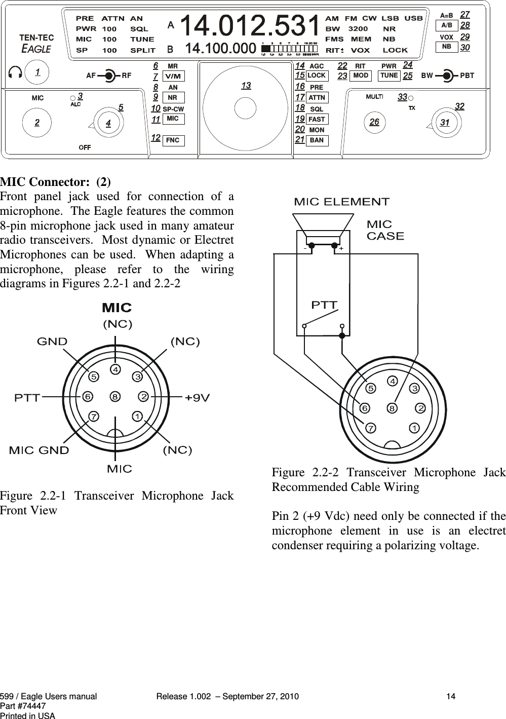
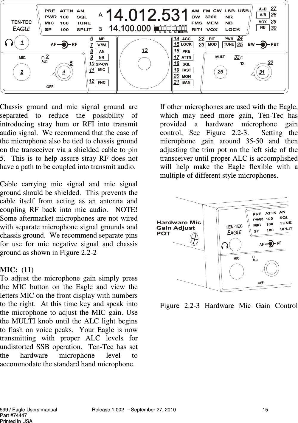
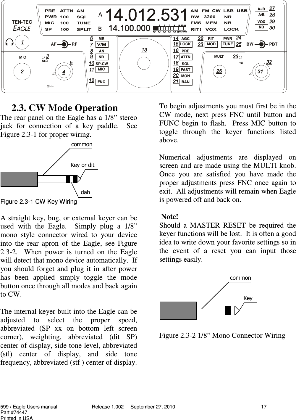
User Manual
Discussion / Help
Navigation