Tera Tron GX120 Inductive System User Manual Annex No 5
Tera Tron GmbH Inductive System Annex No 5
Manual
Annex No.5
Page 1 of 7
User Manual
Hilti GX 120
Technical description
RFID-Reader GX120 Von / From: RHE
Datum / Date: 03.08.07
Seite / Page: 1 / 6
Dokumenten-Nr. 2.0
Projekt Hilti GX 120
Dokumentenversion 1.0 Erstelldatum : 03.08.2007
Autor Name Tel. Fax E-Mail
V1.0 Rainer Helberg +49-2261-8082-233 -833 rainer.helberg@teratron.de
Dokumentenstatus released
Vertraulichkeit Strictly confidential
Verteiler Organisation Name
Querverweise
Technical description
RFID-Reader GX120 Von / From: RHE
Datum / Date: 03.08.07
Seite / Page: 2 / 6
1. TECHNICAL DESCRIPTION.......................................................................................2
2. BLOCK DIAGRAM......................................................................................................4
3. GEOMETRY OF PCB..................................................................................................5
4. IMPORTANT REQUEST:............................................................................................5
5. LABEL:........................................................................................................................6
1. Technical Description
The reader is used in a gas can driven direct fastener tool for metal nails.
It is mounted inside of the tool and communicate with special transponders which are fitted at the
gas cans.
It controls the use of the correct gas can for the tool and also it show the user the remaining gas
level inside the can by 5 LED’s. This is possible, by writing the actual needed gas consumption into
the transponder during working after each shot.
The reader is working together with a second electronic which controls the gas growd and generate
the ignition puls for the spark plug.
The communication to the transponder is working with a 125kHz field.
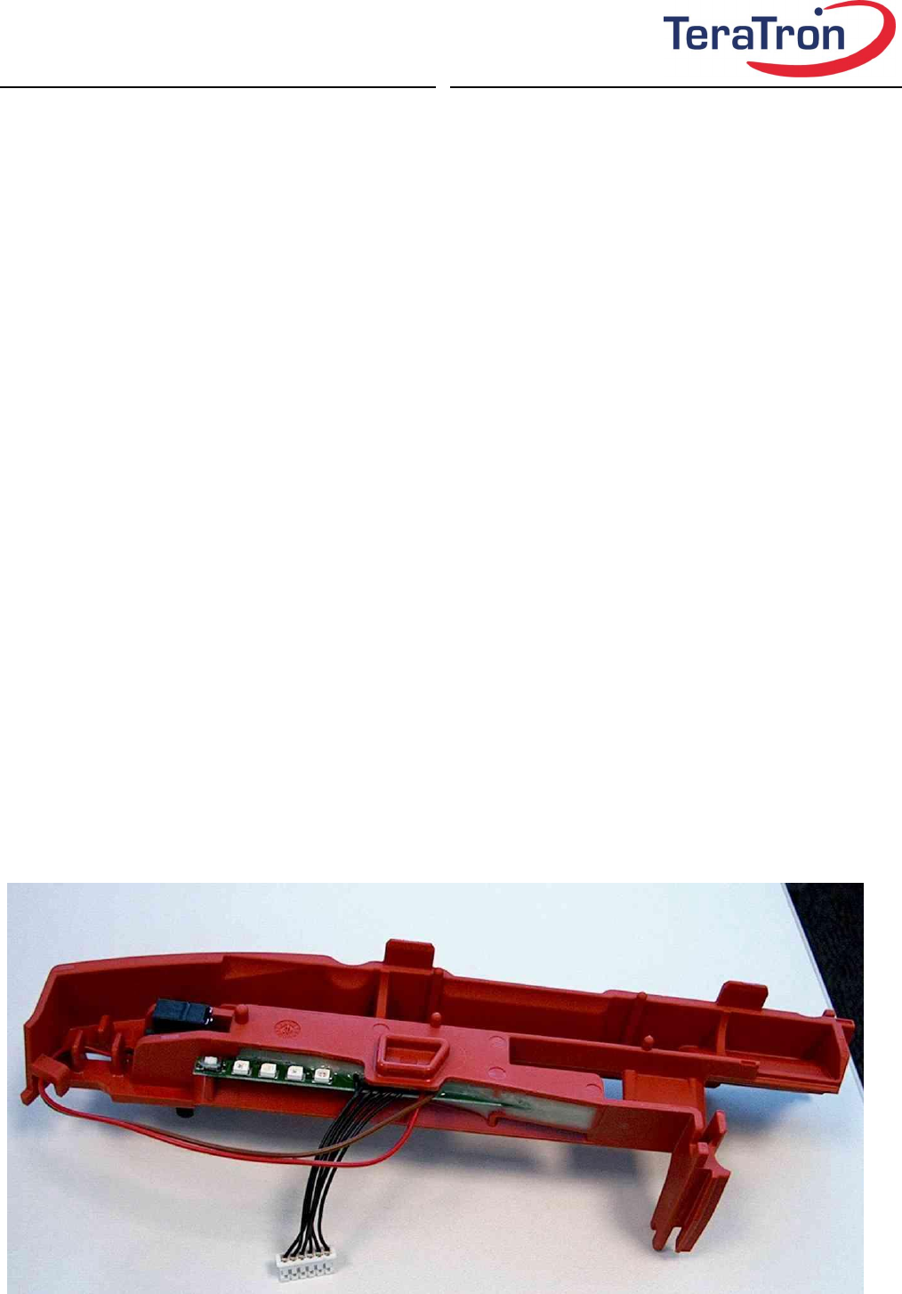
Here you can see the the RFID reader fitted in it’s housing:
Technical description
RFID-Reader GX120 Von / From: RHE
Datum / Date: 03.08.07
Seite / Page: 3 / 6
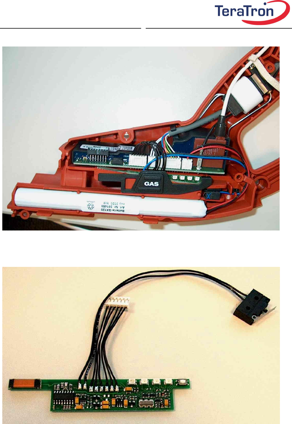
The following picture shows the opened tool with the electronics and the battery:
This picture shows the RFID reader PCB alone. In the left you will see the coil for the 125 kHz
communication with the transponder:
Technical description
RFID-Reader GX120 Von / From: RHE
Datum / Date: 03.08.07
Seite / Page: 4 / 6
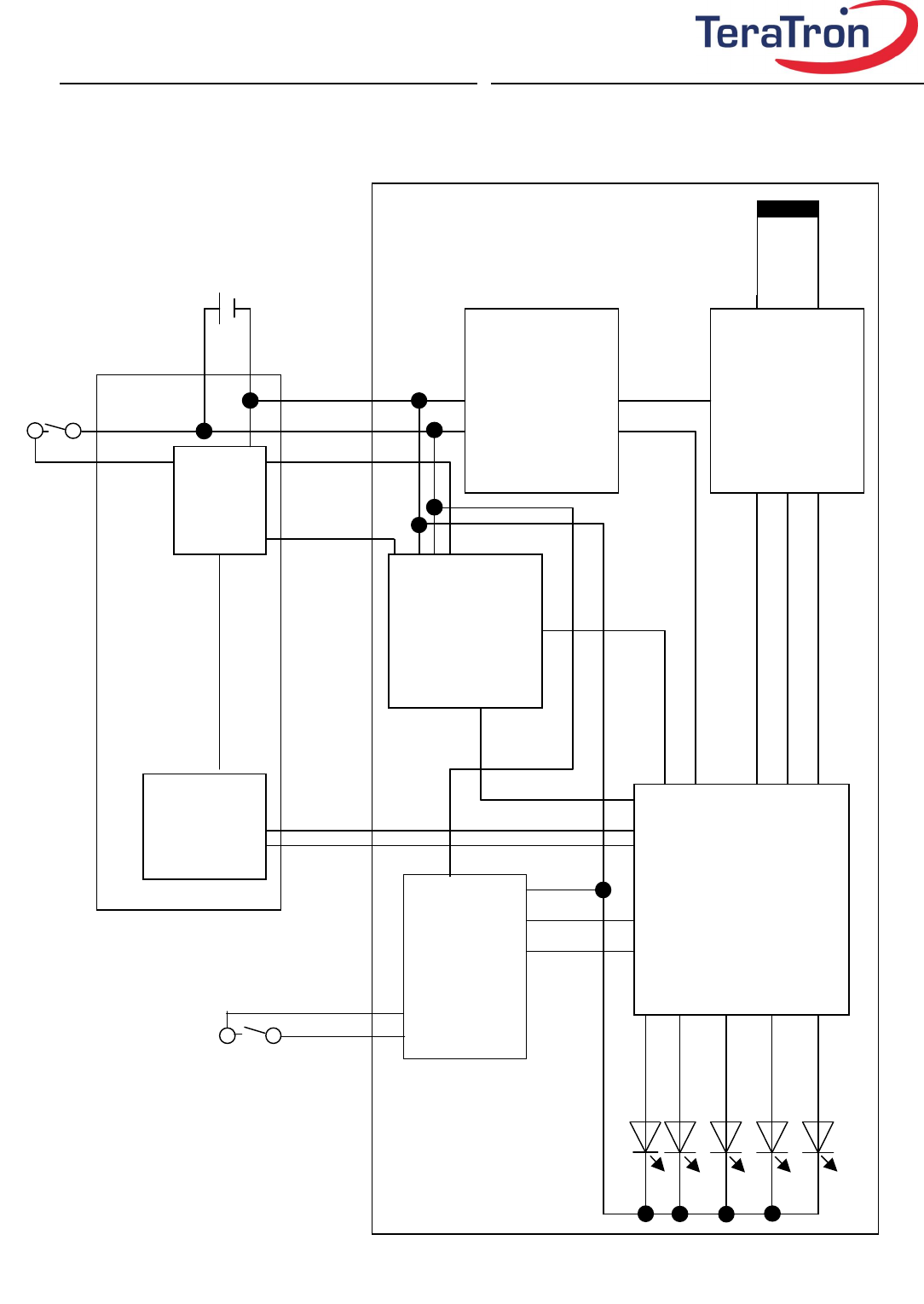
2. Block diagram
LED for gas consumption level
battery
switch-
info
reader-
circuit
power
converter
processor
processor
power
control
logic
nose-
switch
antenna coil for
transponder
communication
gas
can switch
switch
control
logic
communi-
cation lines
communi-
cation lines
Technical description
RFID-Reader GX120 Von / From: RHE
Datum / Date: 03.08.07
Seite / Page: 5 / 6
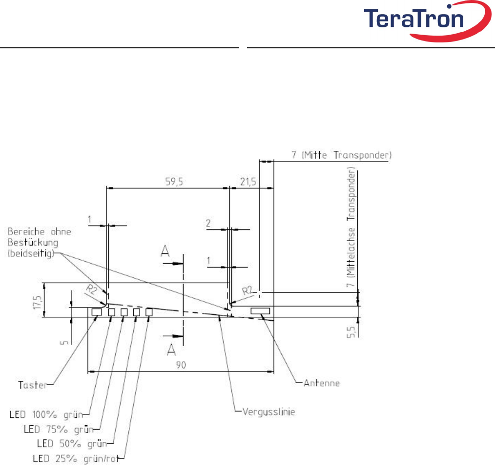
3. Geometry of PCB
The picture shows the size of the PCB:
4. Important request:
This device complies with Part 15 of the FCC Rules. Operation is subject to the following two
conditions:
(1) this device may not cause interference, and
(2) this device must accept any interference received, including interference that may cause
undesired operation of the device."
Any changes or modifications not expressly approved by the party responsible for compliance could
void the user's authority to operate this equipment"
Technical description
RFID-Reader GX120 Von / From: RHE
Datum / Date: 03.08.07
Seite / Page: 6 / 6
5. Label:
The following label will be fixed on each module:
Tested to comply with
FCC Standards
Model: GX120 – Reader
IC: 4430A-GX120
FCC ID: QLXGX120