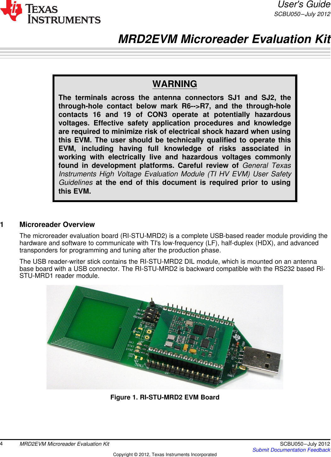
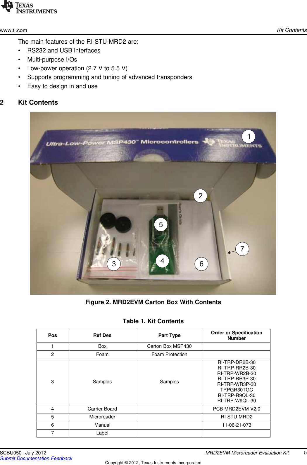
Texas Instruments Deutschland MRD2EVM RFID Reader User Manual MRD2EVM Microreader Evaluation Kit
Texas Instruments Deutschland GmbH RFID Reader MRD2EVM Microreader Evaluation Kit
UserManual.wiki
>
Texas Instruments Deutschland
>
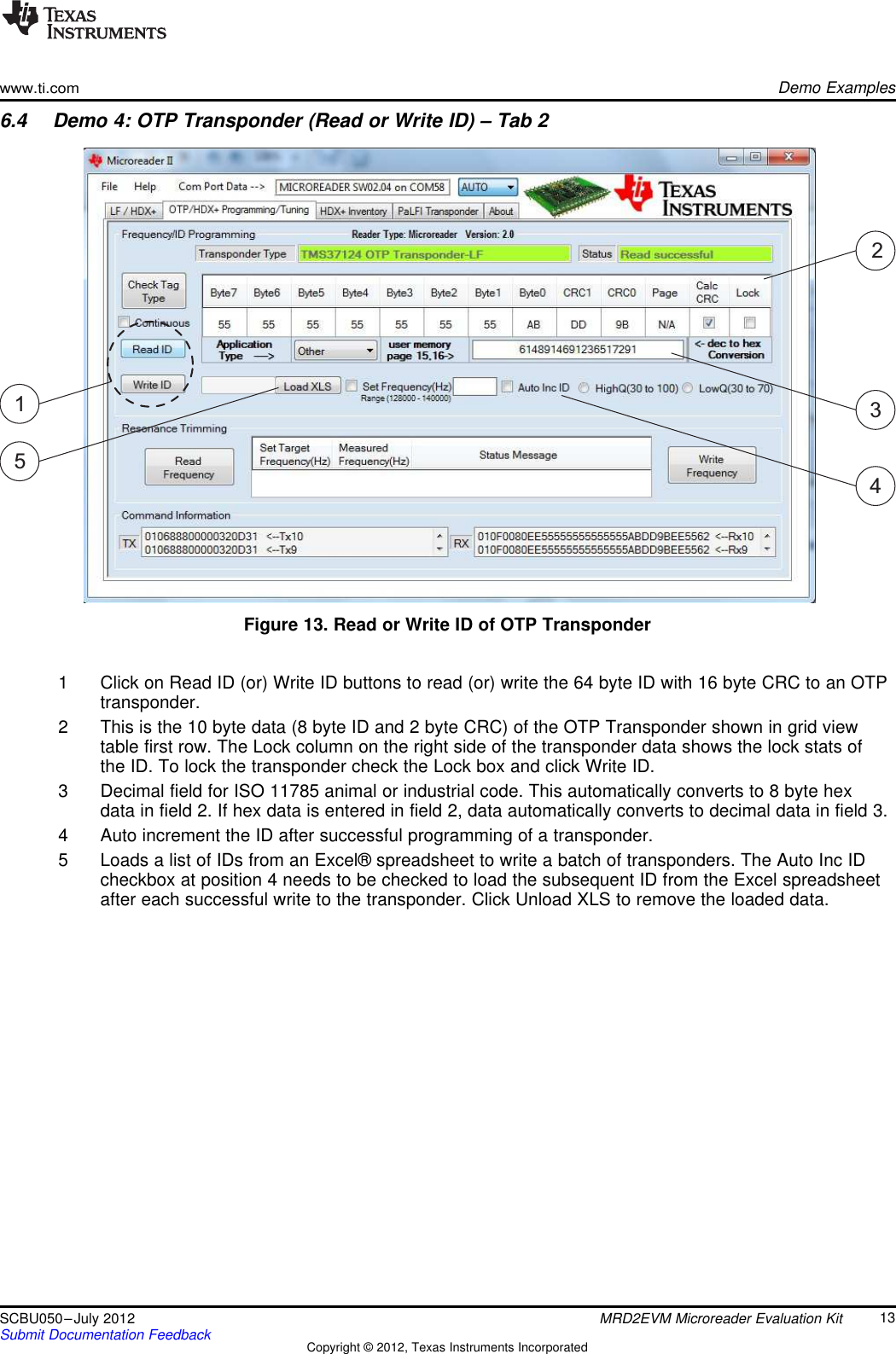
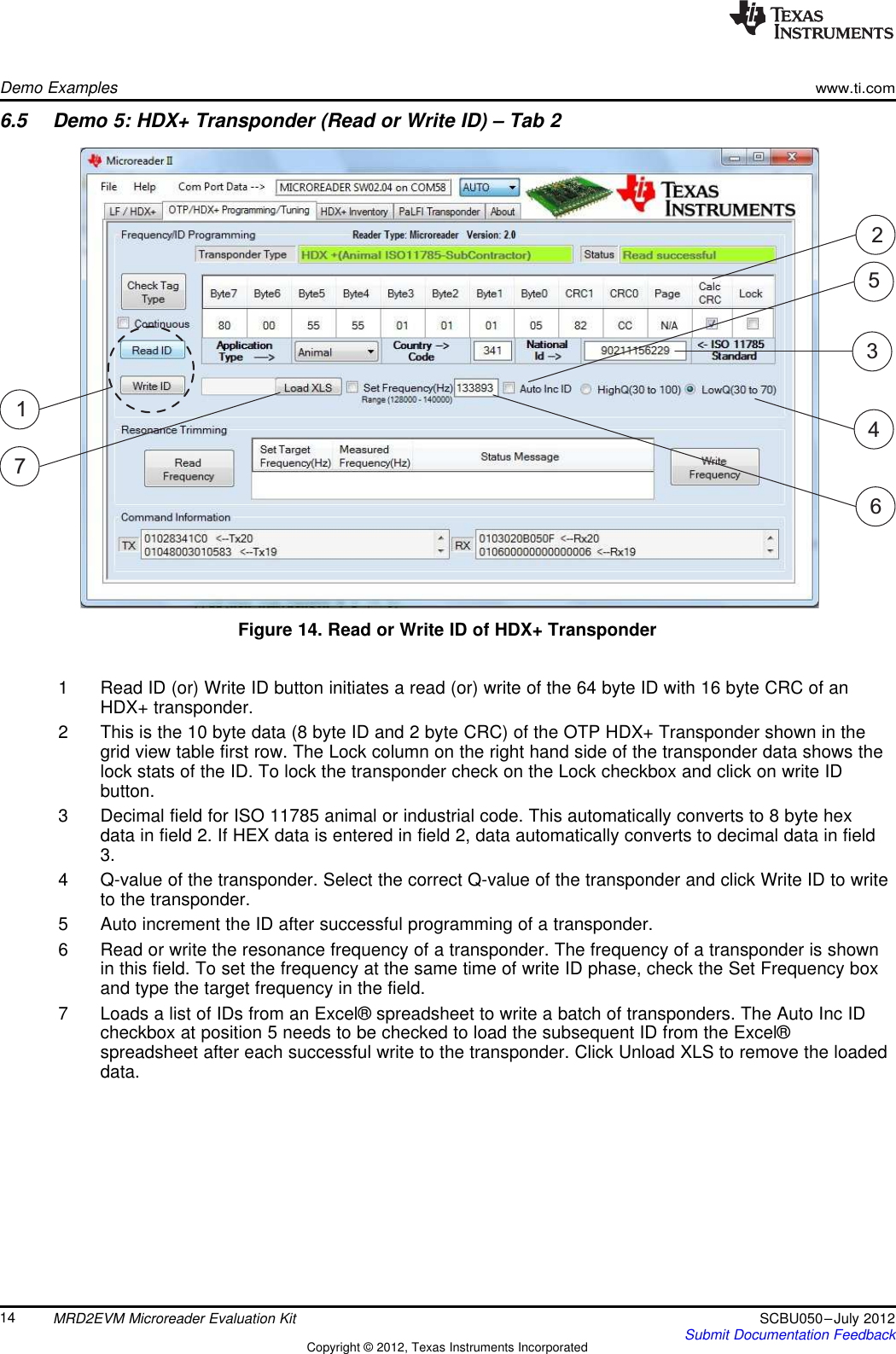
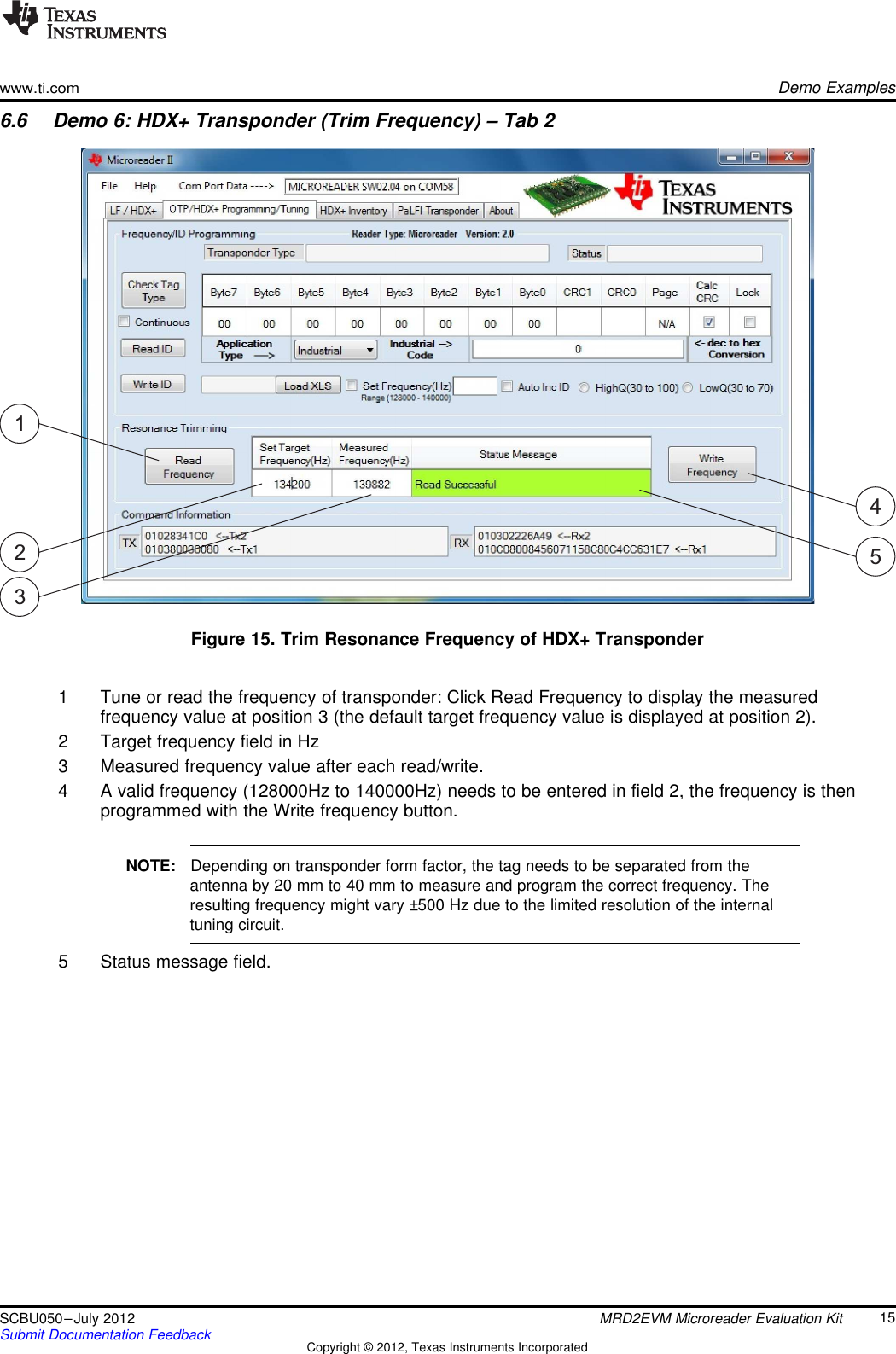
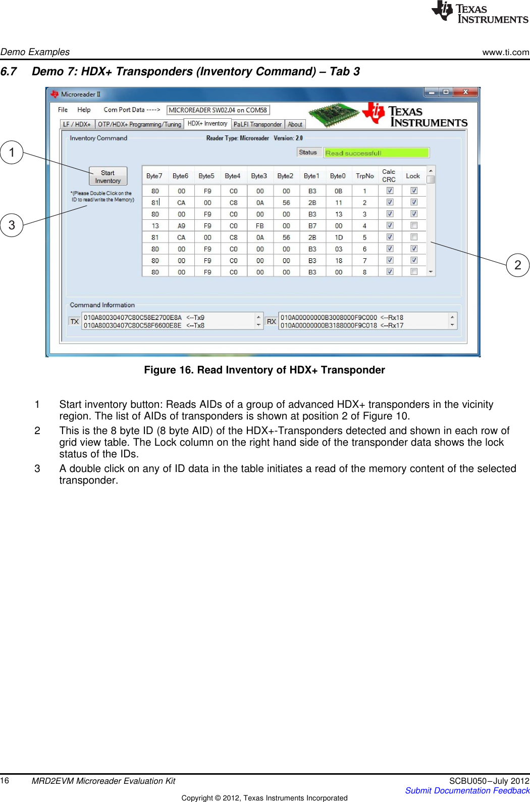
MRD2EVM User Manual
user manual
Navigation menu
Upload a User Manual
Namespaces
Wiki Guide
HTML
PDF
Info
Views
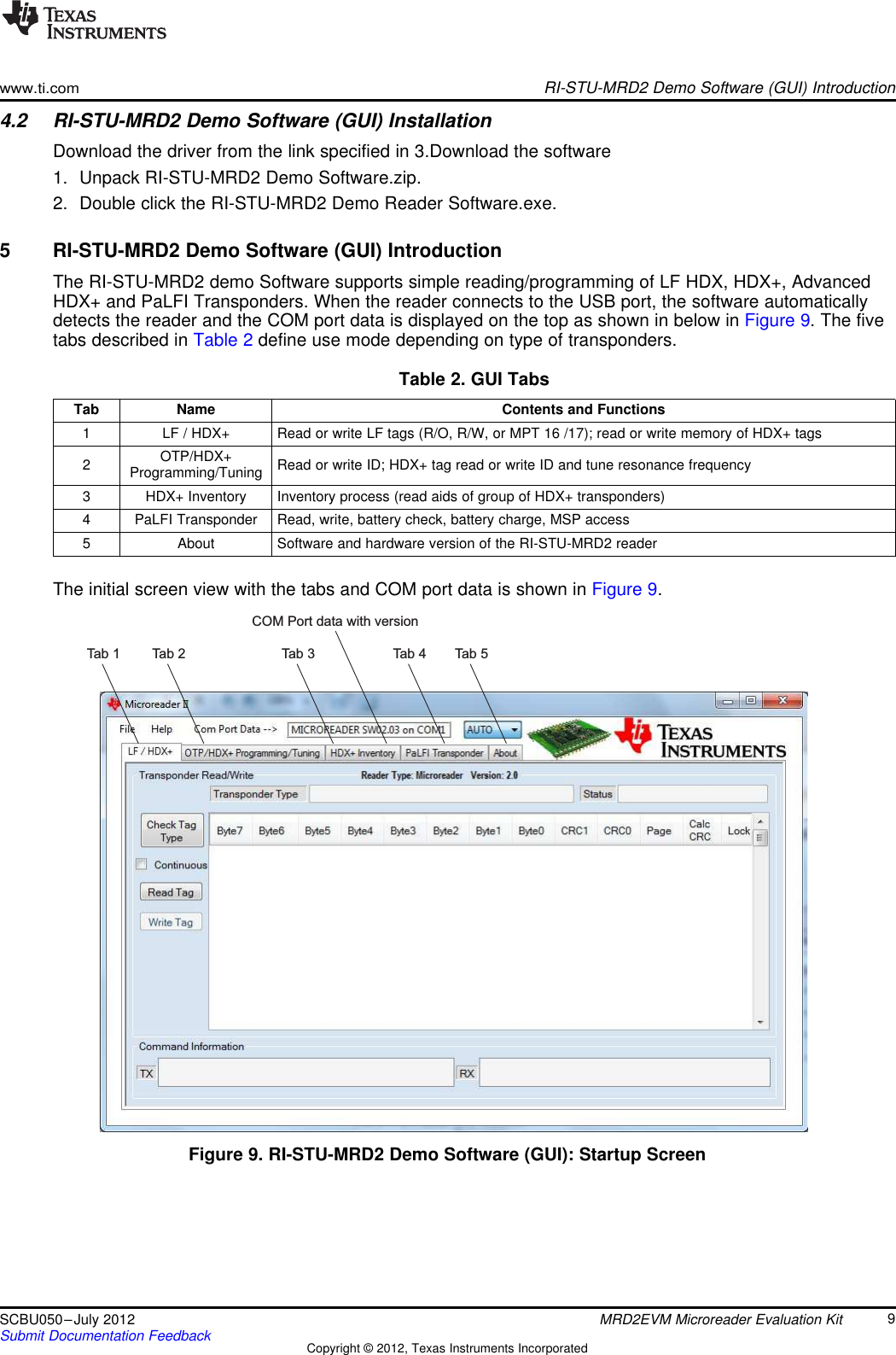
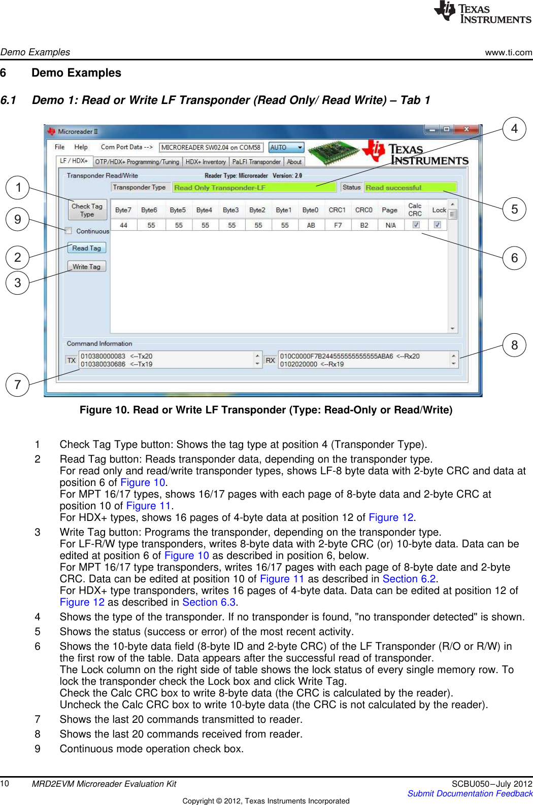
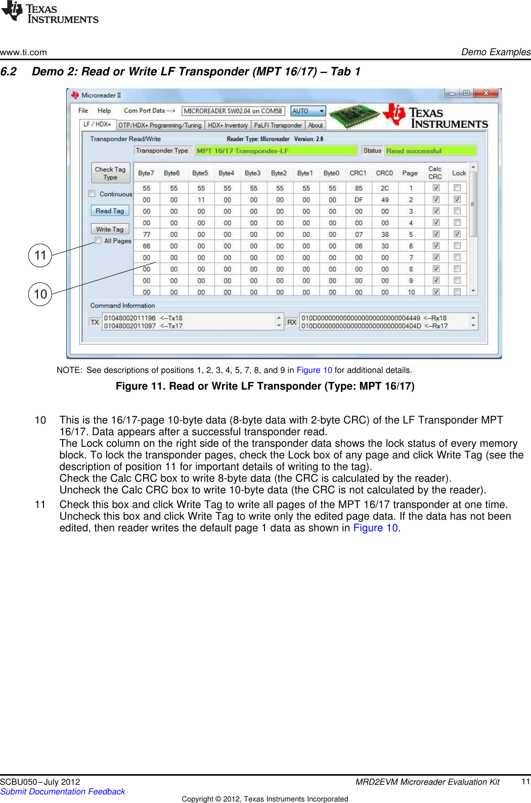
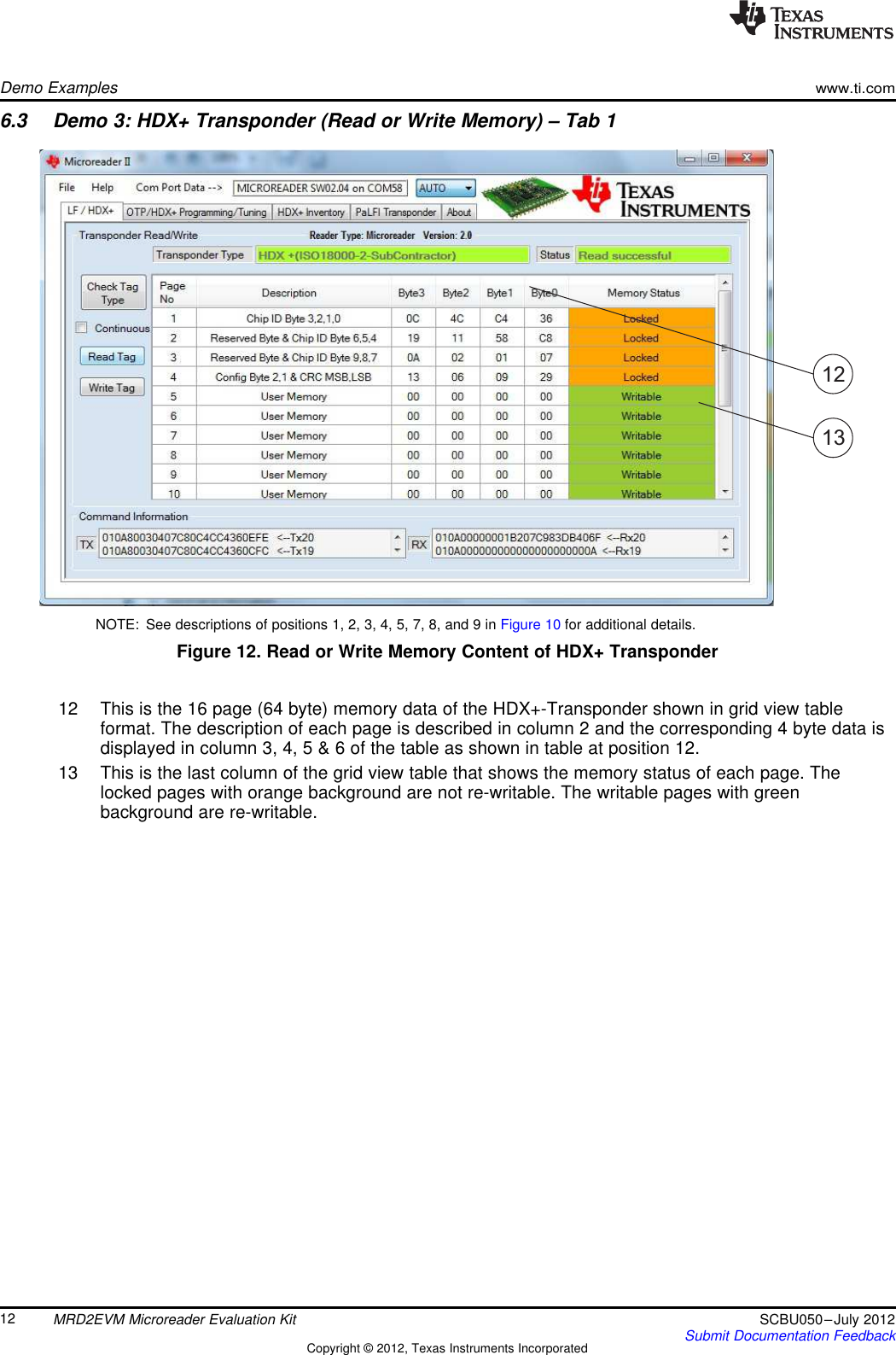
User Manual
Discussion / Help
Navigation