Texas Instruments 2540USB The CC2540Dongle is a development tool for the 2.4 GHz CC2540 BLE System-on-Chip with USB from TI. User Manual CC2540 Development Kit Quick Start Guide
Texas Instruments Inc. The CC2540Dongle is a development tool for the 2.4 GHz CC2540 BLE System-on-Chip with USB from TI. CC2540 Development Kit Quick Start Guide
Contents
- 1. user manual1
- 2. user manual2
user manual1
SWRU300
August
2011
Web sites:
www.ti.com/lprf
E2E Forum:
www.ti.com/lprf
-
forum
Make sure to subscribe to the Low
-
Power RF
Newsletter to receive information about updates to
documentation, new product releases
,
and more.
Sign up on the TI web pages.
CC
2540
Development Kit
Quick Start
Guide
Opening the B
ox an
d R
unning the
Bluetooth
®
Low Energy
SimpleBLE
Demo Application
1. Kit Contents
2
x
SmartRF
05EB (the two large boards)
2 x CC
2540 Evaluation Mod
u
les
2 x
Pulse A
ntennas
1 x
CC2540 USB Dongle
Cables
Documentation
Please contact a TI Representative if any parts
are missing from the kit.
2.
Hardware Setup
Connect the antennas to the SMA connector on
the RF evaluation boards. Tighten the antenna’s
screw firmly on to the
SMA connector. If not
properly connected, you might see reduced RF
performance. Next, mount the
CC2540
evaluation modules (
CC2540
EMs) on to
connectors P5 and P6 on the SmartRF05EB.
Make sure that the boards are pressed firmly
into the connectors.
3.
P
ower Options
There are several ways of applying power to
the
SmartRF05
EB.
2 x 1.5 V AA
B
atteries
USB
External Power Supply
For the batteries and USB, there are voltage
regulators on the
SmartRF05EB
that will set
the on
-
board voltage to 3.3 V. The extern
al
power supply should set a voltage that does
no
t exceed 3.3 V.
Note that there should only be one active
power source at any one time.
4. Se
t
Jumper P11
Find jumper P11 on the top side of each
SmartRF05EB. This jumper is used to set the
power sourc
e for the board. Set P11 to “1
-
2” if
you are using battery power. Set P11 to “2
-
3” if
you are using USB or an external power supply.
5
.
Turn on the Boards
Once you have set P11, find switch P8 on the
top side
of each SmartRF05EB. To power up
the boards, flip the switch from the “OFF”
position to “ON”
6
.
Start
-
up Screen
One of the CC2540
EMs
will be pre
-
loaded
with the SimpleBLECentral application, while
the other will be pre
-
loaded with the
SimpleBLEPeripheral
application. The LCD
screens on the two SmartRF05EBs should
display message
s
similar to those below:
The “0x…” value displayed on each board is
the device address. Every CC2540 dev
ice
has
a unique address.
7
.
Us
ing the Joystick
The SimpleBLEPeripheral application runs
autonomously and does not require any user
interaction. The SimpleBLECentral application,
however,
requires user interaction by means of
joystick U1. Find joystick U1 on the top side of
the SmartRF
05EB, immediately below the LCD.
The joystick has five different movements: it can
be moved up, down, left, right, and it can pressed
in like a button. Each movement performs
different actions depending on the state of the
device.
8
.
Device Discovery
Before the two
devices can connect,
the central device
must first discover the
peripheral device. To
perform device
discovery, press up on
joystick U1 once. The
LCD on the central
device should display
“Discovering…”.
After a few seco
nds, it should display “Devices
Found 1 / <
-
To Select”. This means that the
central device successfully discovered the
peripheral. Press left on joystick U1 to view the
address of the peripheral device. This address
should match the address seen on the
pe
ripheral’s LCD.
9
.
Establish Connection
To establish a
connection with the
peripheral, press
joystick U1 in
towards the board
(push it in like it is a
button). Once the
connection is
established, the
central devi
ce will
automatically perform service discovery on the
peripheral using the
BLE
GATT protocol. This
should complete within a few
seconds.
The two LCD screens should appear as in the
images below, with the central still displaying
the peripheral’s address
and the peripheral
having changed from “Advertising” to
“Connected”:
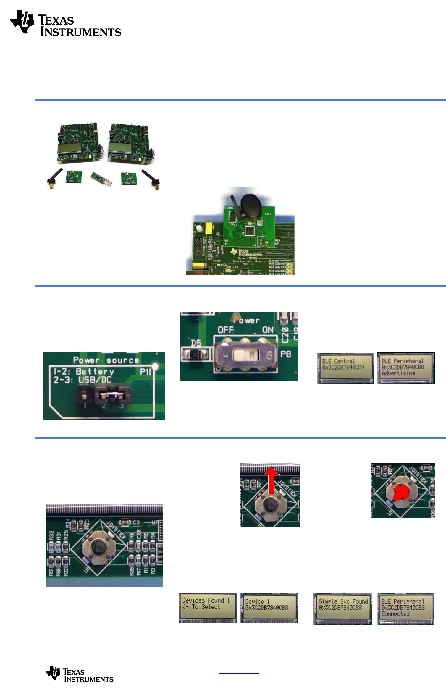
10
.
Connected Operations
Once the connection has been established and
service discovery is complete, you can perform
the following operation
s using joystick U1 on the
central device:
Read / Write Data
–
U1
UP
RSSI Monitoring
–
U1
DOWN
Connection Parameter Update
–
U1
RIGHT
Terminate Link
–
U1
IN
(towards the board)
1
1
.
Read / Write Data
P
ressing up on U1 will send a read
request to the
peripheral device. One byte of data will be read,
and the value will be displayed. Pressing up
again will send a write request, and one byte of
data will be written to the peripheral. The
peripheral’s LCD should display the written value
ea
ch time this is done
.
Bluetooth
low energy is an ideal technology for
transmission of small amounts of data between
two devices
while consuming very little power, as
is demonstrated here.
Continuing to press up o
n the joystick will
alternate between reads and writes
, with the
value incrementing each time
.
1
2
.
Monitor RSSI
P
ressing down on U1 will turn on RSSI (received
signal strength indication) monitoring. The RSSI
will be displayed on the LCD in units of negat
ive
dBm.
If the boards are moved farther apart from each
other, the RSSI will drop (since the value is
negative, a higher number means lower RSSI). If
they are moved closer together, the RSSI should
rise.
Pressing down on U1 again w
ill turn off RSSI
monitoring.
1
3
. Connection Parameter
Update
P
ressing
right
on U1 will send a
connection
parameter update request to the peripheral to
use a longer connection interval. This will result
in much longer latency when performing data
reads a
nd writes; however the power consumed
by both devices is significantly reduced.
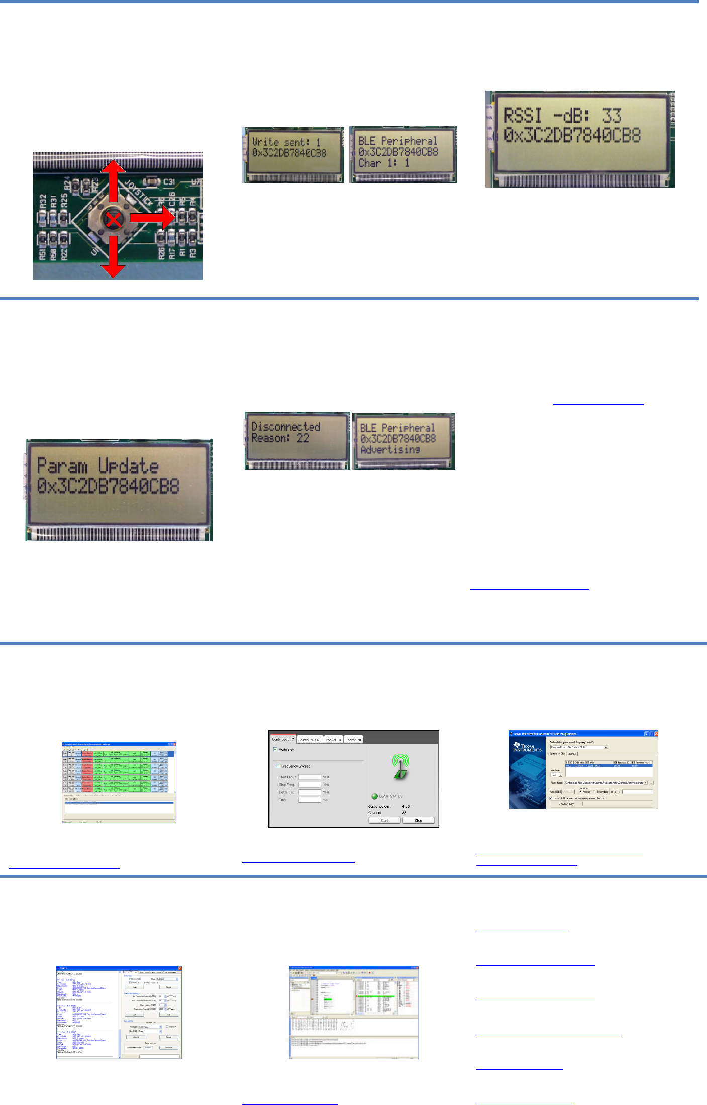
1
4
.
Terminate Link
P
ressing U1 in
towards the board
will terminate
the link. The peripheral will return to an
advertising state
.
The central device will
display
a “Reason” code, which indicates why the
disconnection occurred (values are defined in the
BLE stack API).
In this case, the reason code of 22 indicates that
the link termination was initiated by the centra
l
device. In the e
vent that the peripheral device
goes out of range or has power disconnected
from it, you will see a reason code of
8
which
indicates that a link timeout has occurred.
Y
ou can
now
perform
device discovery and re
-
connect to the peripheral
if desired.
1
5
.
SimpleBLE Demo Source
Code
The project and source code
files
for these
applications
(as well as many others)
are
included with the CC2540 Bluetooth low energy
(BLE) stack from Texas Instruments, which can
be downloaded at
www.ti.com/blestack
.
The two projects implementing this demo are
called SimpleBLECentral (CC2540EM Master
configuration) and SimpleBLEPeripheral
(CC2540 Slave configuration)
.
These can be
modified as desired, and should provide
a good
framework for developing your own custom BLE
applications.
More details on these
projects
can be found
within the CC2540 BLE Software Developer’s
Guide, which is included with the stack. More
information on the CC2540 Development Kit can
be found i
n the CC2540DK User’s Guide, which
can be downloaded at
www.ti.com/lit/pdf/swru301
.
A
dditional Tools
and
Links
BLE Packet Sniffer
The CC2540 USB Dongle included with the
development kit can be used as
a BLE sniffer and
monitor packets while the SimpleBLE Demo is
running.
The SmartRF Protocol Packet Sniffer software
can be downloaded
from
www.ti.com/packetsniffer
SmartRF
™
Studio
Sma
rtRF Studio allows you to configure the radio,
run RF performance tests, and run link tests
between the two SmartRF05EBs.
SmartRF Studio can be downloaded
from
www.ti.com/smartrfstudio
SmartRF Flash Programmer
Texas Instruments has a simple tool which can
be used to program and flash the CC2540
SmartRF Flash Programmer can be
downloaded from
focus.ti.com/docs/toolsw/folders/print/
flash
-
programmer.html
BTool
BTool is a Windows application that allows you to
control a central device
using the serial interface
and perform various
BLE
functions
while
connected to a peripheral device.
BTool is included as part of the installation of the
BLE stack (see “Useful Link
s
” to the right).
IAR Embedded Workbench
To develop software, program, and debug the
CC2540, you should use IAR Embedded
Workbench for 8051
.
More
information on IAR EW8051, including a
free evaluation version download, can be found at
www.iar.com/ew8051
.
Useful Links
TI BLE Stack and Software:
www.ti.com/blestack
CC2540 Development Kit User Guide:
www.ti.com/lit/pdf/swru301
CC2540
BLE Software Developer’s Guide:
www.ti.com/lit
/pdf/swru271
CC2540 User
’
s
Guide:
http://www.ti.com/lit
/pdf/swr
u
191
CC2540 Product Page:
www.ti.com/cc2540
For additional help, visit the TI E2E Forums:
www.ti.com/lprf
-
forum

IMPORTANT NOTICE
Texas Instruments Incorporated and its subsidiaries (TI) reserve the right to make corrections, modifications, enhancements, improvements,
and other changes to its products and services at any time and to discontinue any product or service without notice. Customers should
obtain the latest relevant information before placing orders and should verify that such information is current and complete. All products are
sold subject to TI’s terms and conditions of sale supplied at the time of order acknowledgment.
TI warrants performance of its hardware products to the specifications applicable at the time of sale in accordance with TI’s standard
warranty. Testing and other quality control techniques are used to the extent TI deems necessary to support this warranty. Except where
mandated by government requirements, testing of all parameters of each product is not necessarily performed.
TI assumes no liability for applications assistance or customer product design. Customers are responsible for their products and
applications using TI components. To minimize the risks associated with customer products and applications, customers should provide
adequate design and operating safeguards.
TI does not warrant or represent that any license, either express or implied, is granted under any TI patent right, copyright, mask work right,
or other TI intellectual property right relating to any combination, machine, or process in which TI products or services are used. Information
published by TI regarding third-party products or services does not constitute a license from TI to use such products or services or a
warranty or endorsement thereof. Use of such information may require a license from a third party under the patents or other intellectual
property of the third party, or a license from TI under the patents or other intellectual property of TI.
Reproduction of TI information in TI data books or data sheets is permissible only if reproduction is without alteration and is accompanied
by all associated warranties, conditions, limitations, and notices. Reproduction of this information with alteration is an unfair and deceptive
business practice. TI is not responsible or liable for such altered documentation. Information of third parties may be subject to additional
restrictions.
Resale of TI products or services with statements different from or beyond the parameters stated by TI for that product or service voids all
express and any implied warranties for the associated TI product or service and is an unfair and deceptive business practice. TI is not
responsible or liable for any such statements.
TI products are not authorized for use in safety-critical applications (such as life support) where a failure of the TI product would reasonably
be expected to cause severe personal injury or death, unless officers of the parties have executed an agreement specifically governing
such use. Buyers represent that they have all necessary expertise in the safety and regulatory ramifications of their applications, and
acknowledge and agree that they are solely responsible for all legal, regulatory and safety-related requirements concerning their products
and any use of TI products in such safety-critical applications, notwithstanding any applications-related information or support that may be
provided by TI. Further, Buyers must fully indemnify TI and its representatives against any damages arising out of the use of TI products in
such safety-critical applications.
TI products are neither designed nor intended for use in military/aerospace applications or environments unless the TI products are
specifically designated by TI as military-grade or "enhanced plastic." Only products designated by TI as military-grade meet military
specifications. Buyers acknowledge and agree that any such use of TI products which TI has not designated as military-grade is solely at
the Buyer's risk, and that they are solely responsible for compliance with all legal and regulatory requirements in connection with such use.
TI products are neither designed nor intended for use in automotive applications or environments unless the specific TI products are
designated by TI as compliant with ISO/TS 16949 requirements. Buyers acknowledge and agree that, if they use any non-designated
products in automotive applications, TI will not be responsible for any failure to meet such requirements.
Following are URLs where you can obtain information on other Texas Instruments products and application solutions:
Products Applications
Audio www.ti.com/audio Communications and Telecom www.ti.com/communications
Amplifiers amplifier.ti.com Computers and Peripherals www.ti.com/computers
Data Converters dataconverter.ti.com Consumer Electronics www.ti.com/consumer-apps
DLP® Products www.dlp.com Energy and Lighting www.ti.com/energy
DSP dsp.ti.com Industrial www.ti.com/industrial
Clocks and Timers www.ti.com/clocks Medical www.ti.com/medical
Interface interface.ti.com Security www.ti.com/security
Logic logic.ti.com Space, Avionics and Defense www.ti.com/space-avionics-defense
Power Mgmt power.ti.com Transportation and www.ti.com/automotive
Automotive
Microcontrollers microcontroller.ti.com Video and Imaging www.ti.com/video
RFID www.ti-rfid.com Wireless www.ti.com/wireless-apps
RF/IF and ZigBee® Solutions www.ti.com/lprf
TI E2E Community Home Page e2e.ti.com
Mailing Address: Texas Instruments, Post Office Box 655303, Dallas, Texas 75265
Copyright © 2011, Texas Instruments Incorporated