Texas Instruments FPTVEH Radio Frequency Identification Transponder User Manual 11 09 05 700
Texas Instruments Inc Radio Frequency Identification Transponder 11 09 05 700
Contents
- 1. Hardware Specification
- 2. Software Specification
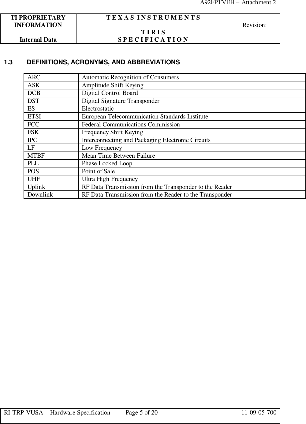
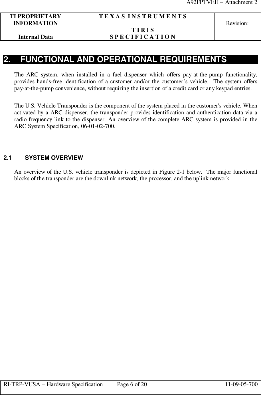
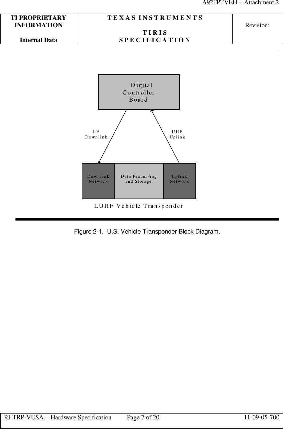
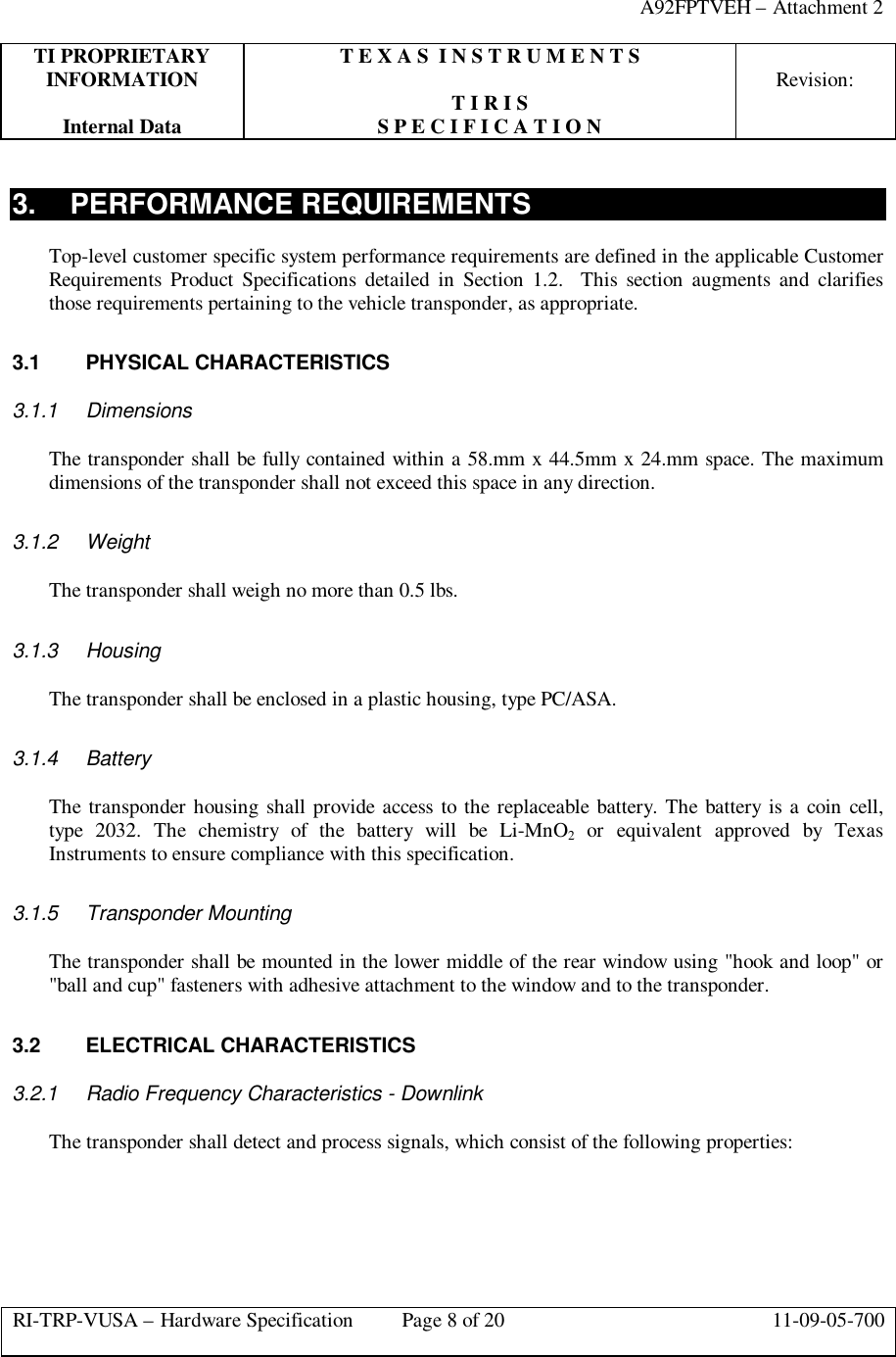
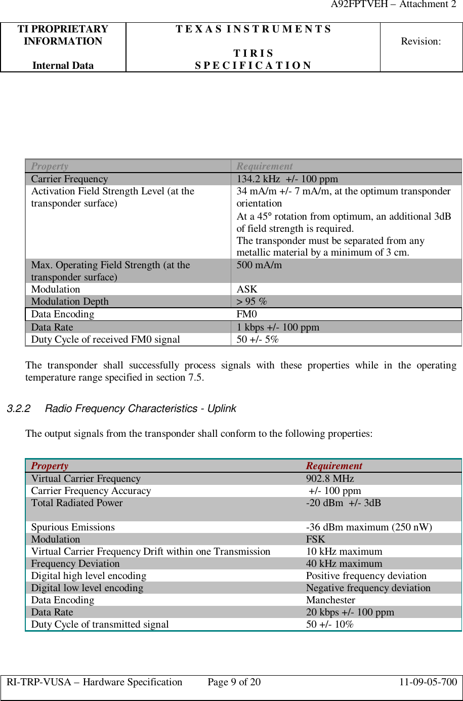
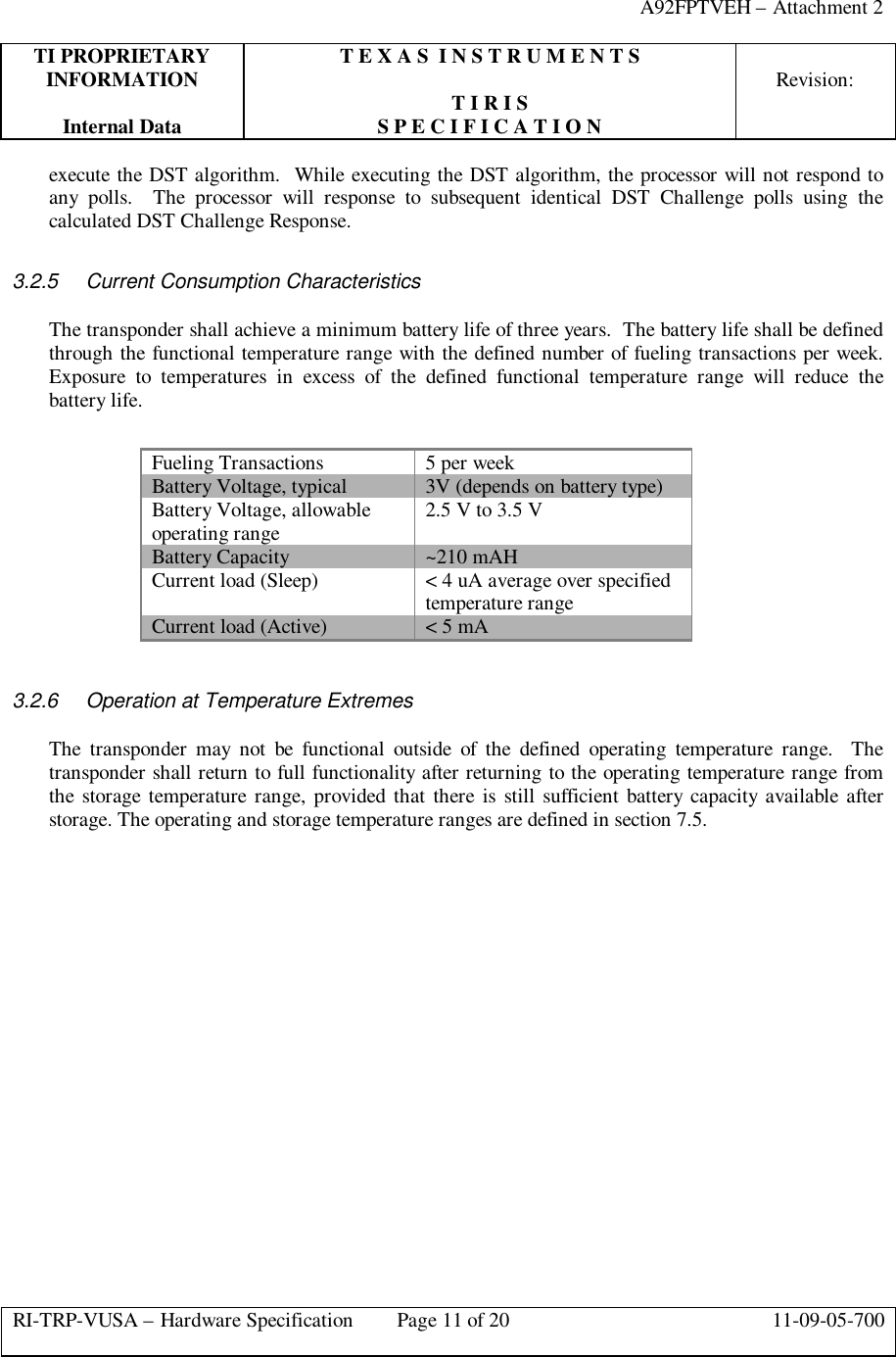
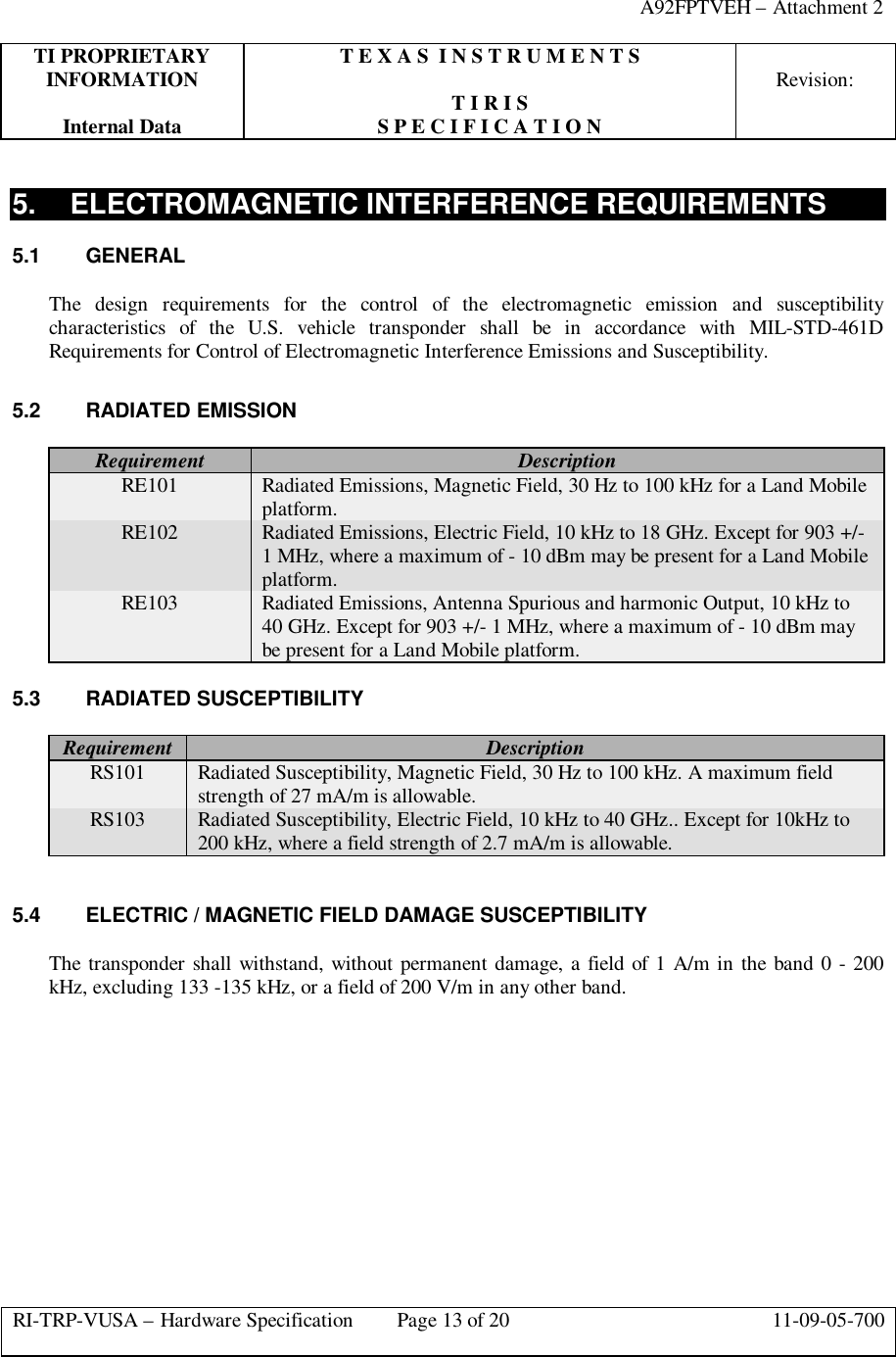
Hardware Specification
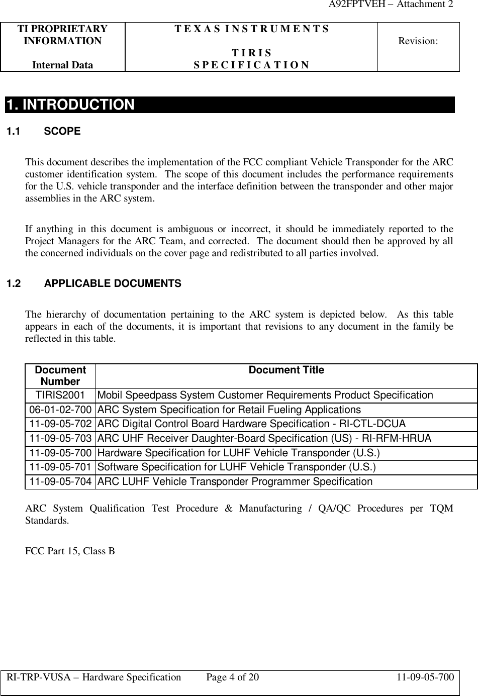

![A92FPTVEH – Attachment 2TI PROPRIETARY T E X A S I N S T R U M E N T SINFORMATION Revision:T I R I SInternal Data S P E C I F I C A T I O NRI-TRP-VUSA – Hardware Specification Page 20 of 20 11-09-05-700Continuous: 21.67 mA-Hours(1 mA * [(5 Min/Day)/ (60 Min/Hour)]* 5 Days/Week * 52 Weeks/Year)Pulsed: 2.60 mA-Hours(4 mA * [(6 mS/200 mS * 5 Min/Day)/(60 Min/Hour)] * 5 Days/Week * 52 Weeks/Year) ==================== Total 52.29 mA-Hours/YearCalculated Life: 4.02 Years(210 mA-Hour / 52.29 mA-Hour/Year)](https://usermanual.wiki/Texas-Instruments/FPTVEH.Hardware-Specification/User-Guide-59041-Page-20.png)