Texas Instruments FPTVEH Radio Frequency Identification Transponder User Manual 11 09 05 701
Texas Instruments Inc Radio Frequency Identification Transponder 11 09 05 701
Contents
- 1. Hardware Specification
- 2. Software Specification
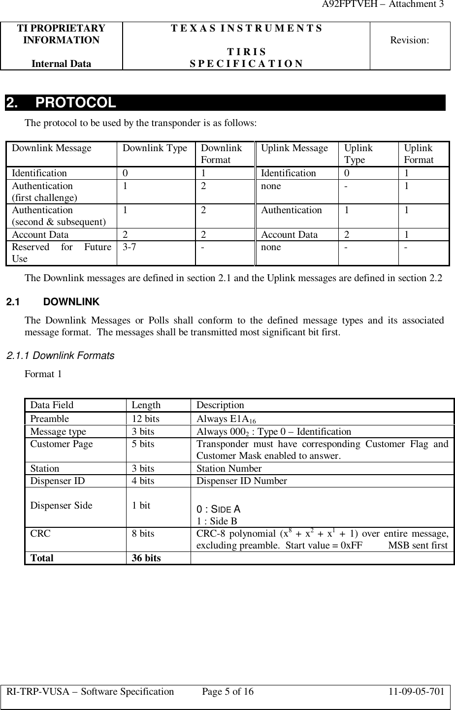
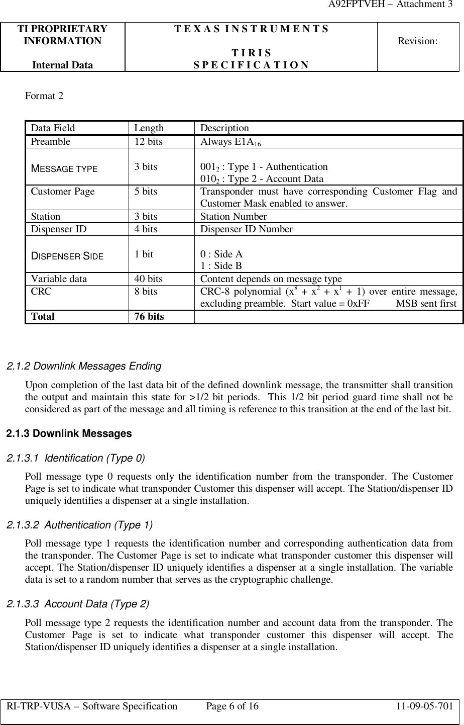
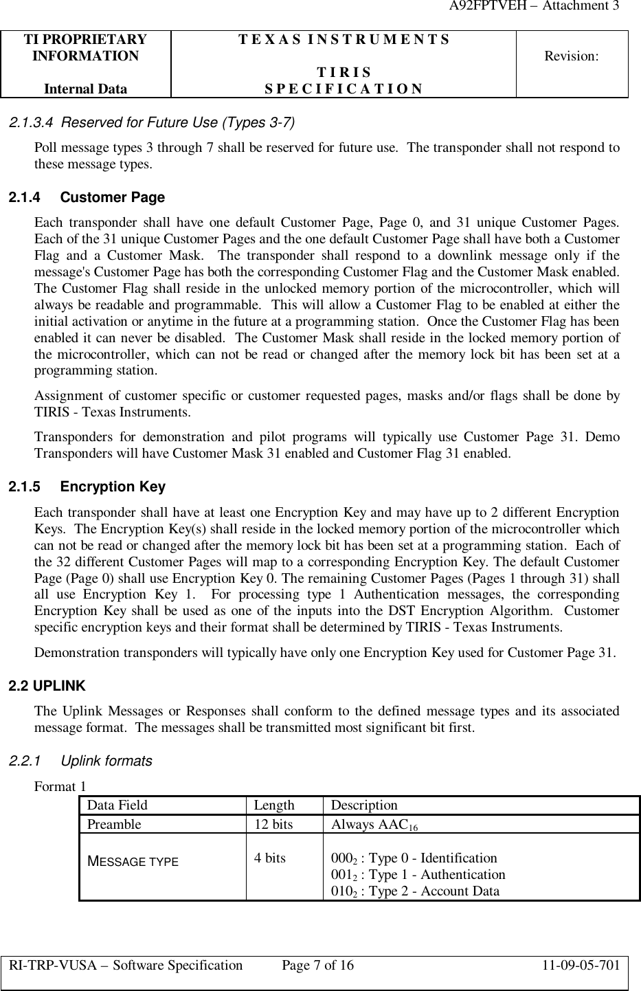
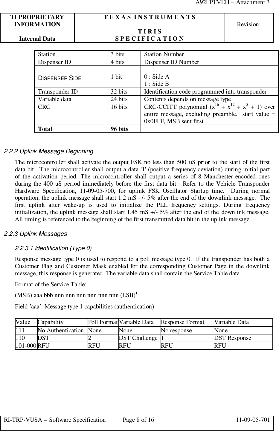
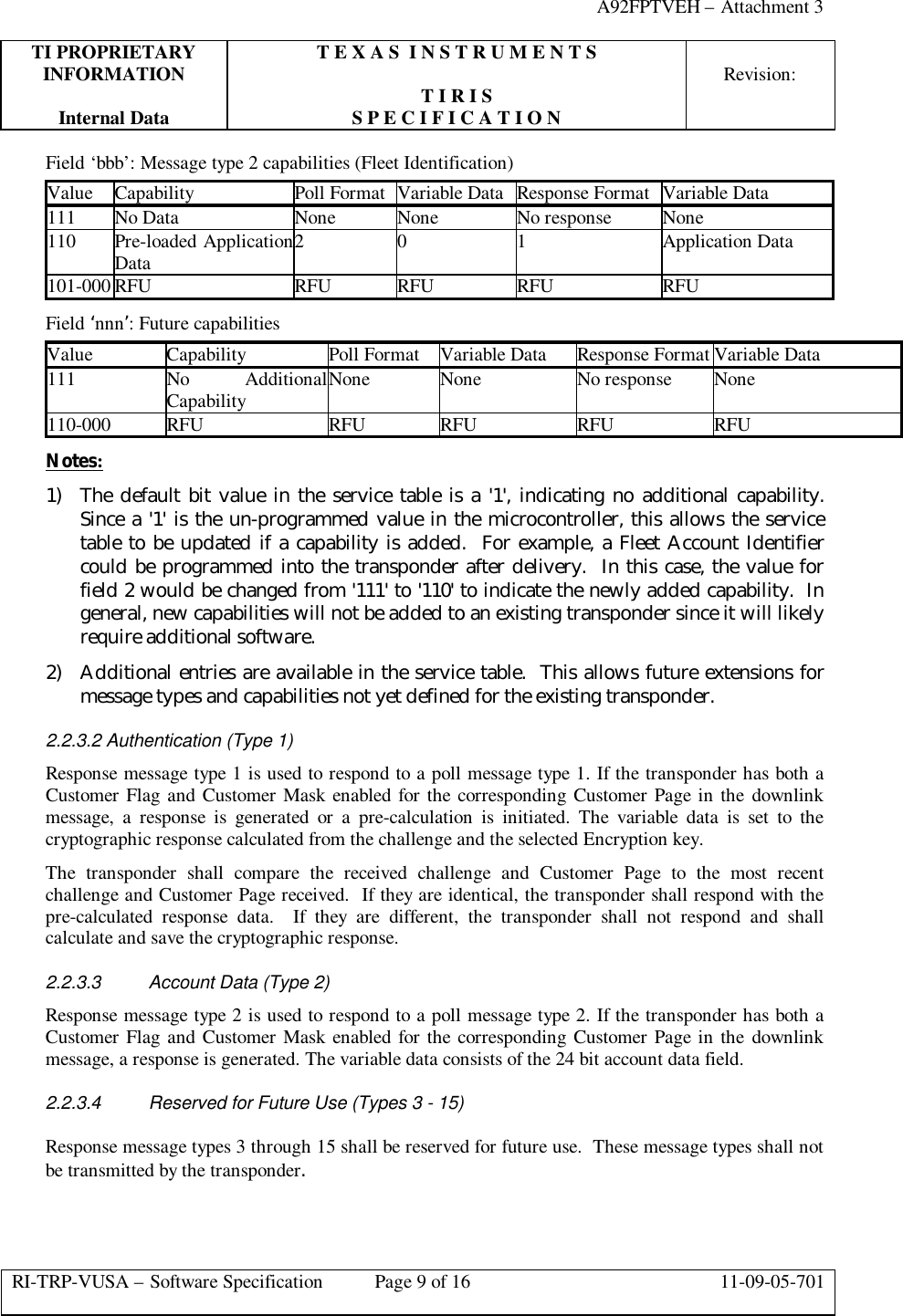
Software Specification