Texas Instruments FPTVEH Radio Frequency Identification Transponder User Manual 11 09 05 701
Texas Instruments Inc Radio Frequency Identification Transponder 11 09 05 701
Contents
- 1. Hardware Specification
- 2. Software Specification
Software Specification
A92FPTVEH – Attachment 3
TI PROPRIETARY T E X A S I N S T R U M E N T S Originator:
INFORMATION Phillip LaCroix
T I R I S Effective Date:
Internal Data S P E C I F I C A T I O N July 14, 1999
Revision: Date:
Approval: Approval: Approval:
Function: Engineering Function: Operations Function: Software
Name: Loek D’Hont Name: Paul Angelo Name: Krishna D.
Date: Date: Date
RI-TRP-VUSA – Software Specification Page 1 of 16 11-09-05-701
Software Specification
for
LUHF Vehicle Transponder (U.S.)
RI-TRP-VUSA
PRINTED COPIES OF THIS SPECIFICATION
ARE NOT CONTROLLED DOCUMENTS.
VERIFY THEIR CORRECT REVISION BEFORE USING.

A92FPTVEH – Attachment 3
TI PROPRIETARY T E X A S I N S T R U M E N T S
INFORMATION Revision:
T I R I S
Internal Data S P E C I F I C A T I O N
RI-TRP-VUSA – Software Specification Page 2 of 16 11-09-05-701
TABLE OF CONTENTS
1. INTRODUCTION …………………………………………………………………………………. 1
1.1 SCOPE........................................................................................................................... 4
1.2 APPLICABLE DOCUMENTS ................................................................................................ 4
1.3 DEFINITIONS, ACRONYMS AND ABBREVIATIONS .................................................................. 4
2. PROTOCOL …………………………………………………………………………………………5
2.1 DOWNLINK ..................................................................................................................... 5
2.1.1 Downlink Formats....................................................................................................................... 5
2.1.2 Downlink Messages Ending ....................................................................................................... 6
2.1.3 Downlink Messages ................................................................................................................... 6
2.1.3.1 Identification (Type 0)..................................................................................................... 6
2.1.3.2 Authentication (Type 1) .................................................................................................. 6
2.1.3.3 Account Data (Type 2).................................................................................................... 6
2.1.3.4 Reserved for Future Use (Types 3-7).............................................................................. 7
2.1.4 Customer Page ......................................................................................................................... 7
2.1.5 Encryption Key .......................................................................................................................... 7
2.2 UPLINK .................................................................................................................................. 7
2.2.1 Uplink formats ............................................................................................................................ 7
2.2.2 Uplink Message Beginning......................................................................................................... 8
2.2.3 Uplink Messages........................................................................................................................ 8
2.2.3.1 Identification (Type 0)............................................................................................................. 8
2.2.3.2 Authentication (Type 1) .......................................................................................................... 9
2.2.3.3 Account Data (Type 2).................................................................................................... 9
2.2.3.4 Reserved for Future Use (Types 3 - 15) .......................................................................... 9
3. FUNCTIONAL REQUIREMENTS
…………………………………………………………….…..10
3.1 SOFTWARE OVERVIEW ...................................................................................................10
3.1.1 WAKE-UP................................................................................................................................ 12
3.1.2 WAIT........................................................................................................................................ 12
3.1.3 RECEIVE................................................................................................................................. 12
3.1.4 MESSAGE PROCESSING...................................................................................................... 13
3.1.5 RESPONSE ............................................................................................................................ 13
3.1.5.1 VCO Control .................................................................................................................13
3.1.6 DST ENCODER ...................................................................................................................... 13
3.1.7 SLEEP..................................................................................................................................... 14
4MICROCONTROLLER HARDWARE INTERFACE …………………………………………..15
5QUALITY ASSURANCE PROVISIONS ………………………………………………………..16

A92FPTVEH – Attachment 3
TI PROPRIETARY T E X A S I N S T R U M E N T S
INFORMATION Revision:
T I R I S
Internal Data S P E C I F I C A T I O N
RI-TRP-VUSA – Software Specification Page 3 of 16 11-09-05-701

A92FPTVEH – Attachment 3
TI PROPRIETARY T E X A S I N S T R U M E N T S
INFORMATION Revision:
T I R I S
Internal Data S P E C I F I C A T I O N
RI-TRP-VUSA – Software Specification Page 4 of 16 11-09-05-701
1. INTRODUCTION
1.1 SCOPE
This document describes the LUHF Vehicle Transponder Software Specification definition to
implement the TIRIS Automatic Recognition of Consumers (ARC) system. The scope of this
document extends from the Vehicle Transponder Hardware Specification. The interrelationships and
interfaces between the Vehicle Transponder Hardware Specification and this software specification
are defined in detail. The relationships of this software specification within the ARC system are
contained in the higher-level specifications (see 1.2 Applicable Documents, below).
If anything in this document is ambiguous or incorrect, it should be immediately reported to the
Project Managers for the Texas Instruments ARC Team, and corrected. This document is a TI
internal document only.
1.2 APPLICABLE DOCUMENTS
The hierarchy of documentation pertaining to this specification is depicted below.
Document
Number Document Title
06-01-02-700 ARC System Specification (U.S)
11-09-05-700 Hardware Specification for LUHF Vehicle Transponder
11-09-05-701 Software Specification for LUHF Vehicle Transponder
24-09-05-012 TIRIS Digital Signature Transponder Algorithm and Software Requirement
TQM TIRIS QUALITY MANUAL
1.3 DEFINITIONS, ACRONYMS, AND ABBREVIATIONS
ARC Automatic Recognition of Consumers
CRC Cyclic Redundancy Check
Downlink RF Data Transmission from Dispenser to Transponder (134 kHz Carrier)
LSB Least Significant Bit
LUHF Low / Ultra High Frequency
MSB Most Significant Bit
PLL Phase-Locked Loop
RFU Reserved for Future Use
TIRIS Texas Instruments Registration and Identification System
Uplink RF Data Transmission from Transponder to Dispenser (902.8 MHz Carrier)
VCO Voltage-Controlled Oscillator
A92FPTVEH – Attachment 3
TI PROPRIETARY T E X A S I N S T R U M E N T S
INFORMATION Revision:
T I R I S
Internal Data S P E C I F I C A T I O N
RI-TRP-VUSA – Software Specification Page 5 of 16 11-09-05-701
2. PROTOCOL
The protocol to be used by the transponder is as follows:
Downlink Message Downlink Type Downlink
Format Uplink Message Uplink
Type Uplink
Format
Identification 0 1 Identification 0 1
Authentication
(first challenge) 1 2 none -1
Authentication
(second & subsequent) 1 2 Authentication 1 1
Account Data 2 2 Account Data 2 1
Reserved for Future
Use 3-7 -none - -
The Downlink messages are defined in section 2.1 and the Uplink messages are defined in section 2.2
2.1 DOWNLINK
The Downlink Messages or Polls shall conform to the defined message types and its associated
message format. The messages shall be transmitted most significant bit first.
2.1.1 Downlink Formats
Format 1
Data Field Length Description
Preamble 12 bits Always E1A16
Message type 3 bits Always 0002 : Type 0 – Identification
Customer Page 5 bits Transponder must have corresponding Customer Flag and
Customer Mask enabled to answer.
Station 3 bits Station Number
Dispenser ID 4 bits Dispenser ID Number
Dispenser Side 1 bit 0 : SIDE A
1 : Side B
CRC 8 bits CRC-8 polynomial (x
8
+ x
2
+ x
1
+ 1) over entire message,
excluding preamble. Start value = 0xFF MSB sent first
Total 36 bits

A92FPTVEH – Attachment 3
TI PROPRIETARY T E X A S I N S T R U M E N T S
INFORMATION Revision:
T I R I S
Internal Data S P E C I F I C A T I O N
RI-TRP-VUSA – Software Specification Page 6 of 16 11-09-05-701
Format 2
Data Field Length Description
Preamble 12 bits Always E1A16
MESSAGE TYPE 3 bits 0012 : Type 1 - Authentication
0102 : Type 2 - Account Data
Customer Page 5 bits Transponder must have corresponding Customer Flag and
Customer Mask enabled to answer.
Station 3 bits Station Number
Dispenser ID 4 bits Dispenser ID Number
DISPENSER SIDE 1 bit 0 : Side A
1 : Side B
Variable data 40 bits Content depends on message type
CRC 8 bits CRC-8 polynomial (x
8
+ x
2
+ x
1
+ 1) over entire message,
excluding preamble. Start value = 0xFF MSB sent first
Total 76 bits
2.1.2 Downlink Messages Ending
Upon completion of the last data bit of the defined downlink message, the transmitter shall transition
the output and maintain this state for >1/2 bit periods. This 1/2 bit period guard time shall not be
considered as part of the message and all timing is reference to this transition at the end of the last bit.
2.1.3 Downlink Messages
2.1.3.1 Identification (Type 0)
Poll message type 0 requests only the identification number from the transponder. The Customer
Page is set to indicate what transponder Customer this dispenser will accept. The Station/dispenser ID
uniquely identifies a dispenser at a single installation.
2.1.3.2 Authentication (Type 1)
Poll message type 1 requests the identification number and corresponding authentication data from
the transponder. The Customer Page is set to indicate what transponder customer this dispenser will
accept. The Station/dispenser ID uniquely identifies a dispenser at a single installation. The variable
data is set to a random number that serves as the cryptographic challenge.
2.1.3.3 Account Data (Type 2)
Poll message type 2 requests the identification number and account data from the transponder. The
Customer Page is set to indicate what transponder customer this dispenser will accept. The
Station/dispenser ID uniquely identifies a dispenser at a single installation.

A92FPTVEH – Attachment 3
TI PROPRIETARY T E X A S I N S T R U M E N T S
INFORMATION Revision:
T I R I S
Internal Data S P E C I F I C A T I O N
RI-TRP-VUSA – Software Specification Page 7 of 16 11-09-05-701
2.1.3.4 Reserved for Future Use (Types 3-7)
Poll message types 3 through 7 shall be reserved for future use. The transponder shall not respond to
these message types.
2.1.4 Customer Page
Each transponder shall have one default Customer Page, Page 0, and 31 unique Customer Pages.
Each of the 31 unique Customer Pages and the one default Customer Page shall have both a Customer
Flag and a Customer Mask. The transponder shall respond to a downlink message only if the
message's Customer Page has both the corresponding Customer Flag and the Customer Mask enabled.
The Customer Flag shall reside in the unlocked memory portion of the microcontroller, which will
always be readable and programmable. This will allow a Customer Flag to be enabled at either the
initial activation or anytime in the future at a programming station. Once the Customer Flag has been
enabled it can never be disabled. The Customer Mask shall reside in the locked memory portion of
the microcontroller, which can not be read or changed after the memory lock bit has been set at a
programming station.
Assignment of customer specific or customer requested pages, masks and/or flags shall be done by
TIRIS - Texas Instruments.
Transponders for demonstration and pilot programs will typically use Customer Page 31. Demo
Transponders will have Customer Mask 31 enabled and Customer Flag 31 enabled.
2.1.5 Encryption Key
Each transponder shall have at least one Encryption Key and may have up to 2 different Encryption
Keys. The Encryption Key(s) shall reside in the locked memory portion of the microcontroller which
can not be read or changed after the memory lock bit has been set at a programming station. Each of
the 32 different Customer Pages will map to a corresponding Encryption Key. The default Customer
Page (Page 0) shall use Encryption Key 0. The remaining Customer Pages (Pages 1 through 31) shall
all use Encryption Key 1. For processing type 1 Authentication messages, the corresponding
Encryption Key shall be used as one of the inputs into the DST Encryption Algorithm. Customer
specific encryption keys and their format shall be determined by TIRIS - Texas Instruments.
Demonstration transponders will typically have only one Encryption Key used for Customer Page 31.
2.2 UPLINK
The Uplink Messages or Responses shall conform to the defined message types and its associated
message format. The messages shall be transmitted most significant bit first.
2.2.1 Uplink formats
Format 1
Data Field Length Description
Preamble 12 bits Always AAC16
MESSAGE TYPE 4 bits 0002 : Type 0 - Identification
0012 : Type 1 - Authentication
0102 : Type 2 - Account Data

A92FPTVEH – Attachment 3
TI PROPRIETARY T E X A S I N S T R U M E N T S
INFORMATION Revision:
T I R I S
Internal Data S P E C I F I C A T I O N
RI-TRP-VUSA – Software Specification Page 8 of 16 11-09-05-701
Station 3 bits Station Number
Dispenser ID 4 bits Dispenser ID Number
DISPENSER SIDE 1 bit 0 : Side A
1 : Side B
Transponder ID 32 bits Identification code programmed into transponder
Variable data 24 bits Contents depends on message type
CRC 16 bits CRC-CCITT polynomial (x
16
+ x
12
+ x
5
+ 1) over
entire message, excluding preamble. start value =
0x0FFF, MSB sent first
Total 96 bits
2.2.2 Uplink Message Beginning
The microcontroller shall activate the output FSK no less than 500 uS prior to the start of the first
data bit. The microcontroller shall output a data '1' (positive frequency deviation) during initial part
of the activation period. The microcontroller shall output a series of 8 Manchester-encoded ones
during the 400 uS period immediately before the first data bit. Refer to the Vehicle Transponder
Hardware Specification, 11-09-05-700, for uplink FSK Oscillator Startup time. During normal
operation, the uplink message shall start 1.2 mS +/- 5% after the end of the downlink message. The
first uplink after wake-up is used to initialize the PLL frequency settings. During frequency
initialization, the uplink message shall start 1.45 mS +/- 5% after the end of the downlink message.
All timing is referenced to the beginning of the first transmitted data bit in the uplink message.
2.2.3 Uplink Messages
2.2.3.1 Identification (Type 0)
Response message type 0 is used to respond to a poll message type 0. If the transponder has both a
Customer Flag and Customer Mask enabled for the corresponding Customer Page in the downlink
message, this response is generated. The variable data shall contain the Service Table data.
Format of the Service Table:
(MSB) aaa bbb nnn nnn nnn nnn nnn nnn (LSB)1
Field ‘aaa’: Message type 1 capabilities (authentication)
Value Capability Poll Format Variable Data Response Format Variable Data
111 No Authentication None None No response None
110 DST 2DST Challenge 1DST Response
101-000 RFU RFU RFU RFU RFU

A92FPTVEH – Attachment 3
TI PROPRIETARY T E X A S I N S T R U M E N T S
INFORMATION Revision:
T I R I S
Internal Data S P E C I F I C A T I O N
RI-TRP-VUSA – Software Specification Page 9 of 16 11-09-05-701
Field ‘bbb’: Message type 2 capabilities (Fleet Identification)
Value Capability Poll Format Variable Data Response Format Variable Data
111 No Data None None No response None
110
Pre-loaded Application
Data 2 0 1 Application Data
101-000 RFU RFU RFU RFU RFU
Field ‘nnn’: Future capabilities
Value Capability Poll Format Variable Data Response Format Variable Data
111 No Additional
Capability None None No response None
110-000 RFU RFU RFU RFU RFU
Notes:
1) The default bit value in the service table is a '1', indicating no additional capability.
Since a '1' is the un-programmed value in the microcontroller, this allows the service
table to be updated if a capability is added. For example, a Fleet Account Identifier
could be programmed into the transponder after delivery. In this case, the value for
field 2 would be changed from '111' to '110' to indicate the newly added capability. In
general, new capabilities will not be added to an existing transponder since it will likely
require additional software.
2) Additional entries are available in the service table. This allows future extensions for
message types and capabilities not yet defined for the existing transponder.
2.2.3.2 Authentication (Type 1)
Response message type 1 is used to respond to a poll message type 1. If the transponder has both a
Customer Flag and Customer Mask enabled for the corresponding Customer Page in the downlink
message, a response is generated or a pre-calculation is initiated. The variable data is set to the
cryptographic response calculated from the challenge and the selected Encryption key.
The transponder shall compare the received challenge and Customer Page to the most recent
challenge and Customer Page received. If they are identical, the transponder shall respond with the
pre-calculated response data. If they are different, the transponder shall not respond and shall
calculate and save the cryptographic response.
2.2.3.3 Account Data (Type 2)
Response message type 2 is used to respond to a poll message type 2. If the transponder has both a
Customer Flag and Customer Mask enabled for the corresponding Customer Page in the downlink
message, a response is generated. The variable data consists of the 24 bit account data field.
2.2.3.4 Reserved for Future Use (Types 3 - 15)
Response message types 3 through 15 shall be reserved for future use. These message types shall not
be transmitted by the transponder.

A92FPTVEH – Attachment 3
TI PROPRIETARY T E X A S I N S T R U M E N T S
INFORMATION Revision:
T I R I S
Internal Data S P E C I F I C A T I O N
RI-TRP-VUSA – Software Specification Page 10 of 16 11-09-05-701
3. FUNCTIONAL REQUIREMENTS
When the Vehicle Transponder Software is programmed into the Vehicle Transponder's
microcontroller, the software provides the functionality required to:
- Wake-up on DL Data pin transition.
- Decode a 1 kbps, FM0, poll message.
- Process the received poll message and generate a response message.
- Transmit a 20 kbps, Manchester encoded response.
- Go into a low power sleep mode when transmission ceases.
3.1 SOFTWARE OVERVIEW
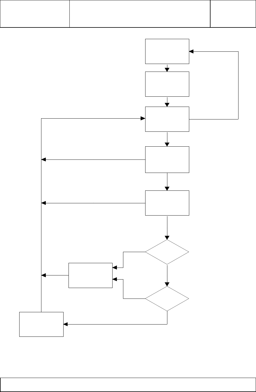
A top-level overview of the Vehicle Transponder Software is depicted in Figure 3-1 below. The
major blocks of the software are the Wake-up, Wait, Receive, Message Processing, Response, and
DST Encoder. The interrelationships of these subsystems are shown in Figure 3-1.
A92FPTVEH – Attachment 3
TI PROPRIETARY T E X A S I N S T R U M E N T S
INFORMATION Revision:
T I R I S
Internal Data S P E C I F I C A T I O N
RI-TRP-VUSA – Software Specification Page 11 of 16 11-09-05-701
Type
6
Sleep
1
Wake-Up
2
Wait
3
Receive
4
Message
Processing
5
DST Encoder
9
Response
8
> 5 Seconds
Transition
Transition
Invalid or Undefined Msg
or Invalid CRC
Invalid
FM0
1st DST
7
DST
Yes
Non
DST
No
Valid
Message
Figure 3-1. Software Flow Diagram.

A92FPTVEH – Attachment 3
TI PROPRIETARY T E X A S I N S T R U M E N T S
INFORMATION Revision:
T I R I S
Internal Data S P E C I F I C A T I O N
RI-TRP-VUSA – Software Specification Page 12 of 16 11-09-05-701
3.1.1 WAKE-UP
The microcontroller shall transition from a low power sleep mode to an initialized active mode within
150 mS of any transition on the DL Data pin. Upon completion of the initialization, the transponder
shall then enter a wait mode.
3.1.2 WAIT
The microcontroller shall enter the wait mode after exiting any of the following modes: Wake-up,
Receive mode with invalid poll, DST calculation, or Response mode. The microcontroller shall
transition to the Receive mode on a transition on the DL Data pin or exit to Sleep mode if there are no
transitions within 5 s +/- 15%.
3.1.3 RECEIVE
The microcontroller shall enter the Receive Mode after an DL Data pin transition from the Wait
mode. In this mode, the microcontroller shall be capable of processing the downlink data with the
protocol as defined in section 2 with the characteristics defined in Doc. No. 11-09-05-700 with the
following additional constraints:
- Less than 100 uS transition time from high to low level input.
- Less than 50 uS transition time from low to high level input.
- FM0 modulation asymmetrical waveform as shown below. This asymmetry is caused by the
transponder detector circuitry, and is not allocated to the Downlink Transmitter.
FM0 Modulation Asymmetry
Input Data Level Minimum Maximum
0Low 0.15 mS 0.65 mS *
0High 0.35 mS 0.85 mS *
1Low 0.65 mS * 1.20 mS
1High 0.85 mS * 1.35 mS
* Note: Interrelated - Data 0 low maximum <=> Data 1 low minimum
Data 0 high maximum <=> Data 1 high minimum
The microcontroller shall exit the Receive mode under one of the following conditions: Invalid Data,
complete reception of a valid Poll, or the end of DL Data pin transitions for greater than 1.5 bit
periods. At any time the microcontroller receives downlink data characteristics that do not conform
to the defined requirements, the microcontroller shall return back to the Wait mode within 100 uS.
As the downlink message begins, the microcontroller must first identify the last four bits of the
preamble (synch). Upon identifying the synch, the message length is set to minimum message length,
and the 8 bit CRC is preloaded with 0xFF. As the message continues, the received data bits are
decoded and stored, and the CRC value is updated with each bit. When the full Message Type has
been received, the message length counter will be updated and control when the full message has
been received. If DL Data pin transitions stop for greater than 1.5 bit periods prior to receiving the
full message, the microcontroller shall exit to Wait mode. When the full message has been received,
the microcontroller shall proceed to the Message Processing mode within 100 uS.

A92FPTVEH – Attachment 3
TI PROPRIETARY T E X A S I N S T R U M E N T S
INFORMATION Revision:
T I R I S
Internal Data S P E C I F I C A T I O N
RI-TRP-VUSA – Software Specification Page 13 of 16 11-09-05-701
3.1.4 MESSAGE PROCESSING
The microcontroller shall complete processing of all received poll information within 400 uS and
transition into one of the following Modes: Wait, Response, or DST Encoder. The received
downlink message shall be checked for the following: CRC is zero; valid Message Type; and
Customer Page has both the Customer Flag and Customer Mask enabled. If any of these are invalid
or inactive, the microcontroller shall exit to Wait mode. The Customer Page, Station, Dispenser ID,
Side, and Variable Data fields received shall be saved for use in both processing and uplink data
message.
If an Authentication Poll is received, the Customer Page, Station, Dispenser ID, Side, and Challenge
(from Variable Data) fields are compared with the stored values from the last DST Encoded fields. If
the fields are different, the microcontroller shall exit to DST Encoder mode. If the fields match, the
microcontroller will then create the appropriate response message array using the Uplink format
defined in section 2 and exit to Response Mode.
If either an Identification or Account Data Poll is received, the microcontroller shall create the
appropriate response message array using the Station, Dispenser ID, and Side, received in the
downlink message. The Uplink format shall be as defined in section 2 and exit to Response Mode.
3.1.5 RESPONSE
The microprocessor shall first activate the VCO in accordance with paragraph 2.2.2 before
transmitting the data on the UL Data pin. The transmit data consists of the response message array
created during the Message processing mode followed by the calculated CRC. The protocol used
shall be as defined in section 2. The transmitted data parameters shall be as specified in the Vehicle
Transponder Hardware Specification, 11-09-05-700, with the following additional requirements.
Parameter Requirement
Data Rate 20 kbps +/- 4%
Duty Cycle 50 +/- 0.5 %
3.1.5.1 VCO Control
The uplink frequency of the transponder is governed by a PLL and VCO combination. A programmed
transponder will contain the appropriate constants to initialize the PLL to the desired uplink
frequency. In order to operate the transmitter during an uplink, the VCO and PLL must be placed in
an active, or powered, state. This is accomplished by setting a program-controlled output of the PLL
to a logic high. When the uplink is complete, the PLL and VCO are set to an inactive, or off, state.
This is accomplished by setting a program-controlled output of the PLL to a logic low. The
microcontroller sets the state of the program-controlled output by sending a serial command message
to the PLL.
3.1.6 DST ENCODER
The microcontroller shall use the DST algorithm as specified in TIRIS Digital Signature Transponder
Algorithm and Software Requirement, #24-09-05-012, to encode the received message. The
microcontroller shall create the encoded response using the challenge data in the variable data field in
the received message and the appropriate Encryption Key stored in the microcontroller locked
memory area. The encoded DST response along with the original Challenge, Customer Page, Station,

A92FPTVEH – Attachment 3
TI PROPRIETARY T E X A S I N S T R U M E N T S
INFORMATION Revision:
T I R I S
Internal Data S P E C I F I C A T I O N
RI-TRP-VUSA – Software Specification Page 14 of 16 11-09-05-701
Dispenser ID, and Side from the received message will then be stored in the DST challenge data area.
The microcontroller must complete the full DST encoding routine and return to the Wait mode within
200 mS. The DST Algorithm will use the 8 msb's of the Transponder ID as the Manufacturer's Code
specified in the DST specification.
3.1.7 SLEEP
The microcontroller shall enter into a low power sleep mode within 100 uS of the start of the sleep
mode processing.

A92FPTVEH – Attachment 3
TI PROPRIETARY T E X A S I N S T R U M E N T S
INFORMATION Revision:
T I R I S
Internal Data S P E C I F I C A T I O N
RI-TRP-VUSA – Software Specification Page 15 of 16 11-09-05-701
4. MICROCONTROLLER HARDWARE INTERFACE
The Microchip PIC12C509 microcontroller interface pin definition from the RF detector and to the
PLL and RF FSK transmitter is as follows:
Name Description Type Pin Number
Vbat Positive Supply Power 1
Gnd Ground Ground 8
OSC1 Oscillator Input I2
OSC2 Oscillator Input I3
VPP /
DL_DATA Programming Power /
Downlink Data I 4
PLL_LE PLL Latch Enable I/O 5
PLL_CLK
/
UL_DATA
PLL Serial Clock / Uplink
Data / Programming
Clock
I/O 6
PLL_DAT
APLL Serial Data /
Programming Data I/O 7
Absolute Maximums
Signal Minimum Maximum
Vcc 0 V 7.0 V
DL_DATA,
UL_DATA,
PLL_LE,
PLL_DATA,
OSC1, OSC2
Gnd –0.6 V Vcc + 0.6 V
Vpp Gnd – 0.6 V 13.5 V
Digital Voltage Level
Digital
Value Minimum Maximum
00 V 0.2 * Vcc
10.2 * Vcc
+ 1V Vcc
Critical System Parameters
Parameter Minimum Maximum
Voh, Ioh=3mA Vcc - 0.7 V -
Vol, Iol = -3mA -0.6 V
Input Leakage -1 uA +1 uA
Input Capacitance -10 pF

A92FPTVEH – Attachment 3
TI PROPRIETARY T E X A S I N S T R U M E N T S
INFORMATION Revision:
T I R I S
Internal Data S P E C I F I C A T I O N
RI-TRP-VUSA – Software Specification Page 16 of 16 11-09-05-701
5. QUALITY ASSURANCE PROVISIONS
The Vehicle Transponder Software shall be designed, controlled, and tested in accordance with the TQM.