Texas Instruments S251B Tiris Reader System User Manual
Texas Instruments Inc Tiris Reader System
UserManual.wiki
>
Texas Instruments
>
S251B User Manual
User Manual
Navigation menu
Upload a User Manual
Namespaces
Wiki Guide
HTML
PDF
Info
Views
User Manual
Discussion / Help
Navigation
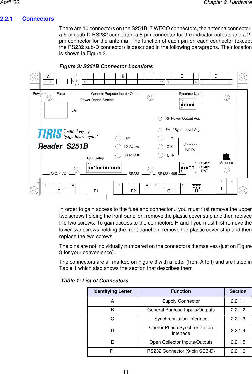
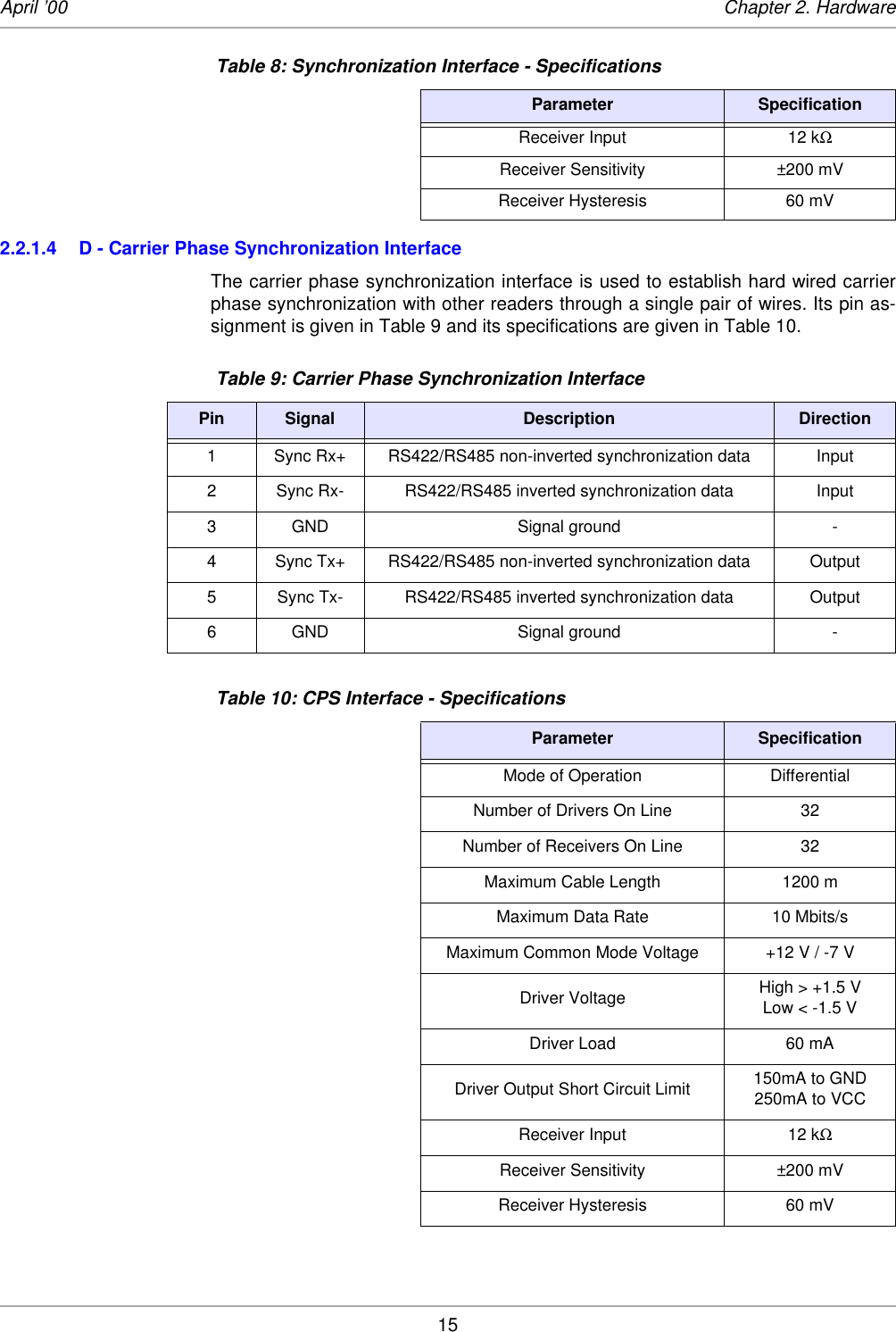
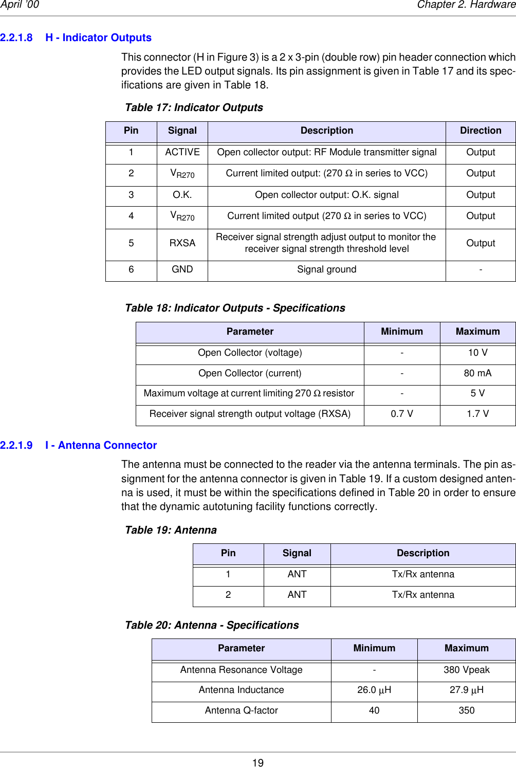
![28S2510 Reader - Reference Guide April ’00Figure 7: Distance between Antennas (top view) Table 27: Distances Between AntennasAntenna type Distance D1 [m] Distance D2 [m]RI_ANT_S02 <=> RI_ANT_S02 0.8 1.0RI_ANT_G01 <=> RI_ANT_G01 1.7 1.5RI_ANT_G02 <=> RI_ANT_G02 1.3 1.0RI_ANT_G04 <=> RI_ANT_G04 2.0 1.7](https://usermanual.wiki/Texas-Instruments/S251B/User-Guide-161171-Page-28.png)