Texas Instruments S251B Tiris Reader System User Manual
Texas Instruments Inc Tiris Reader System
User Manual

1
April ’00 Preface
Series 2000 Reader System
Reader S251B RI-STU-251B
Reference Guide
11-06-21-054 April 2000
FCC ID: A92S251B

2
S2510 Reader - Reference Guide April ’00
Edition One - April 2000
This is the first edition of this manual, it describes the following equipment:
TIRIS Reader S251B RI-STU-251B
Texas Instruments (TI) reserves the right to make changes to its products or services
or to discontinue any product or service at any time without notice. TI provides cus-
tomer assistance in various technical areas, but does not have full access to data
concerning the use and applications of customer's products.
Therefore, TI assumes no liability and is not responsible for customer applications or
product or software design or performance relating to systems or applications incor-
porating TI products. In addition, TI assumes no liability and is not responsible for
infringement of patents and/or any other intellectual or industrial property rights of
third parties, which may result from assistance provided by TI.
TI products are not designed, intended, authorized or warranted to be suitable for life
support applications or any other life critical applications which could involve poten-
tial risk of death, personal injury or severe property or environmental damage.
The TIRIS logo and the word TIRIS are registered trademarks of Texas Instruments
Incorporated.
Copyright 2000 Texas Instruments Incorporated (TI)
This document may be downloaded onto a computer, stored and duplicated as nec-
essary to support the use of the related TI products. Any other type of duplication,
circulation or storage on data carriers in any manner not authorized by TI represents
a violation of the applicable copyright laws and shall be prosecuted.
PREFACE
3
Read This First
About This Guide
This manual describes the TIRIS S251B Reader, its goal is to describe the reader,
how it works, how to install it and how to use it.
Regulatory, safety and warranty notices that must be followed are given in
Chapter 5.
Conventions
If You Need Assistance
Application Centers are located in Europe, North and South America, the Far East
and Australia to provide direct support. For more information, please contact your
nearest TIRIS Sales and Application Center. The contact addresses can be found on
our home page:
http://www.tiris.com
WARNING:
A WARNING IS USED WHERE CARE MUST BE TAKEN, OR A CERTAIN
PROCEDURE MUST BE FOLLOWED IN ORDER TO PREVENT INJURY
OR HARM TO YOUR HEALTH.
CAUTION:
This indicates information on conditions which must be
met, or a procedure which must be followed, which if not
heeded could cause permanent damage to the equipment
or software.
Note:
Indicates conditions which must be met, or procedures which must be
followed, to ensure proper functioning of the equipment or software.
Information:
Indicates information which makes usage of the equipment or soft-
ware easier

4
S2510 Reader - Reference Guide April ’00
Document Overview
Page
Chapter 1: Introduction . . . . . . . . . . . . . . . . . . . . . . . . . . . . . . . . . . . . . . . . . . . . 6
1.1 General............................................................................................... 7
1.2 System Description ............................................................................ 7
1.3 Product Description ............................................................................ 7
Chapter 2: Hardware . . . . . . . . . . . . . . . . . . . . . . . . . . . . . . . . . . . . . . . . . . . . . . 9
2.1 General............................................................................................. 10
2.2 Product Description .......................................................................... 10
2.3 Mechanical Information .................................................................... 22
Chapter 3: Synchronization. . . . . . . . . . . . . . . . . . . . . . . . . . . . . . . . . . . . . . . . 23
3.1 Introduction....................................................................................... 24
3.2 Types of Synchronization ................................................................. 24
Chapter 4: Installation . . . . . . . . . . . . . . . . . . . . . . . . . . . . . . . . . . . . . . . . . . . . 29
4.1 Introduction....................................................................................... 30
4.2 General............................................................................................. 30
4.3 Mechanical Mounting ....................................................................... 30
4.4 Communication ................................................................................ 31
4.5 Synchronization................................................................................ 34
4.6 General Purpose Input/Outputs........................................................ 38
4.7 LED Outputs..................................................................................... 39
4.8 Reset ................................................................................................ 39
4.9 Antenna ............................................................................................ 40
4.10 RF Power Output Adjustment........................................................... 40
Chapter 5: Warnings, Cautions and Notices . . . . . . . . . . . . . . . . . . . . . . . . . . 41
List of Figures
Page
Figure 1: S251B Reader ................................................................................ 7
Figure 2: S251B Front Panel (with connector covers removed) .................. 10
Figure 3: S251B Connector Locations ......................................................... 11
Figure 4: CTL Setup Switches ..................................................................... 20
Figure 5: RS422/RS485/DAT Switches ....................................................... 21
Figure 6: Synchronization DIP Switches...................................................... 21
Figure 7: Distance between Antennas (top view)......................................... 28
Figure 8: Switch Settings for RS422 ............................................................ 33
Figure 9: Switch Settings for RS485 ............................................................ 33
Figure 10: Wired & Combined Wireless/Wired Sync. Interface Connection 34
Figure 11: Master/Slave Sync. Interface Connection (without Ack.) ............ 35
Figure 12: Master/Slave Synchronization Interface Connection .................. 36
Figure 13: Carrier Phase Synchronisation Interface Connection ................. 37
Figure 14: Connecting the LED Outputs ...................................................... 39
Figure 15: RESET Push-button Wiring ........................................................ 39

5
April ’00 Preface
List of Tables
Page
Table 1: List of Connectors .......................................................................... 11
Table 2: Power Range Settings ................................................................... 12
Table 3: Supply Connector........................................................................... 12
Table 4: Supply Connector - Specifications ................................................. 13
Table 5: General Purpose Inputs/Outputs.................................................... 13
Table 6: General Purpose Inputs/Outputs - Specifications .......................... 14
Table 7: Synchronization Interface............................................................... 14
Table 8: Synchronization Interface - Specifications ..................................... 14
Table 9: Carrier Phase Synchronization Interface ....................................... 15
Table 10: CPS Interface - Specifications ..................................................... 15
Table 11: Open Collector & I/Os .................................................................. 16
Table 12: Open Collector & I/Os - Specifications......................................... 16
Table 13: RS232 SUB-D Connector ............................................................ 17
Table 14: RS232 WECO Connector ............................................................ 17
Table 15: RS422/RS485 Connector............................................................. 18
Table 16: RS422/RS485 Communications Interface - Specifications .......... 18
Table 17: Indicator Outputs.......................................................................... 19
Table 18: Indicator Outputs - Specifications ................................................ 19
Table 19: Antenna........................................................................................ 19
Table 20: Antenna - Specifications .............................................................. 19
Table 21: CTL Setup DIP Switches.............................................................. 20
Table 22: I/O Setting Switches (6 & 7) ......................................................... 20
Table 23: RS422/RS485/DAT Settings DIP Switches.................................. 21
Table 24: Synchronization DIP Switches ..................................................... 21
Table 25: Indicators...................................................................................... 22
Table 26: Mechanical Information ................................................................ 22
Table 27: Distances Between Antennas ...................................................... 28
Table 28: RS232 9-pin Connector................................................................ 31
Table 29: RS232 WECO Connector ............................................................ 32
Table 30: RS422/RS485 Connector............................................................. 33
Table 31: Wired and Combined Wireless/Wired Synchronization................ 34
Table 32: Master/Slave Synchronization Without Acknowledgement .......... 35
Table 33: Triggered Synchronization ........................................................... 35
Table 34: Master/Slave Synchronization With Acknowledgement ............... 36
Table 35: General Purpose Inputs/Outputs.................................................. 38
Table 36: Antenna Specifications................................................................. 40

CHAPTER 1
6
Introduction
Chapter 1: Introduction
This introduces you to the S251B Reader, what it is and what it does.
Topic Page
1.1 General..........................................................................................................7
1.2 System Description......................................................................................7
1.3 Product Description.....................................................................................7
1.3.1 Interfaces ...............................................................................................8
1.3.2 Communications Protocols ....................................................................8
7
April ’00 Chapter 1. Introduction
1.1 General
This document provides information about the S251B Reader. It describes the reader
and how to install it.
1.2 System Description
A TIRIS system comprises a reader connected to a control device (usually a host
computer) via an RS232, or an RS422/RS485 interface, an antenna and a trans-
ponder. It is used for wireless identification of TIRIS LF transponders.
The reader sends a 134.2 kHz power pulse to a transponder, the energy of the gen-
erated magnetic field is stored in the capacitor in the transponder and when the pow-
er pulse has finished the transponder immediately sends its data back to the reader.
1.3 Product Description
The Reader is an integral part of a TIRIS system, it provides all of the RF and control
functions required to communicate with TIRIS LF transponders.
The main task of the Reader is to send a power pulse via the antenna to initialize the
transponder, to demodulate the received identification signal and then send the data
to a control device. It is also used to send programming data to Read/Write and Mul-
tipage transponders.
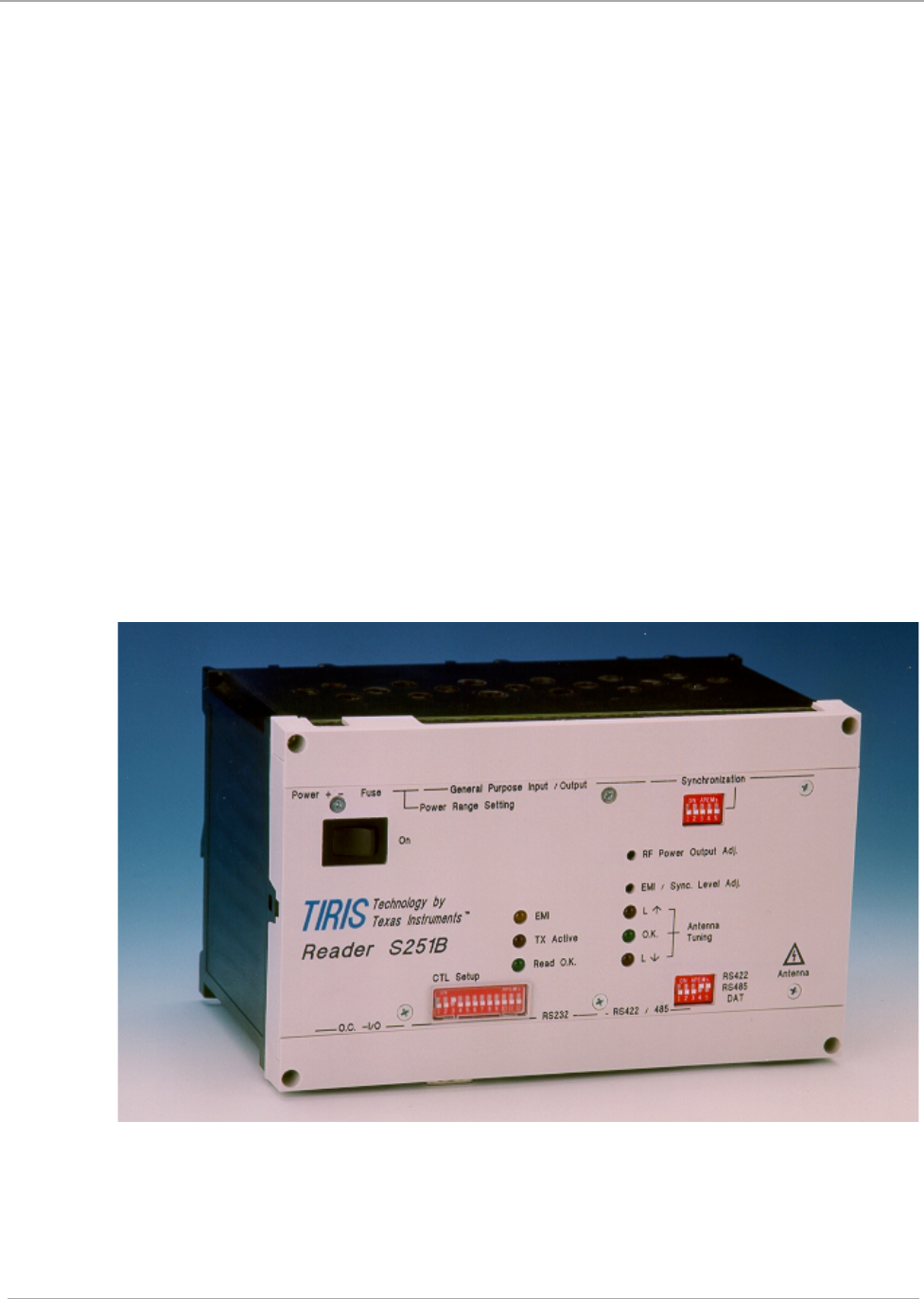
The Reader is housed in an IP20 Polycarbonate box as shown Figure 1.
Figure 1: S251B Reader
If connected via an RS232 or an RS422/RS485 interface the computer sends com-
mands to the reader using one of the two protocols used by the system (ASCII or TI-
RIS Bus Protocol), and the reader then communicates via its antenna with any
transponders within that antenna’s range. The antenna can be mounted up to 5 m
(depending on the antenna) away from the reader.

8
S2510 Reader - Reference Guide April ’00
1.3.1 Interfaces
The reader has the following connections/interfaces:
• Communications interface: RS232, RS422 or RS485 (F & G)
• 8 general purpose I/O lines (B)
• 2 Open Collector outputs (E)
• Synchronization bus (C)
• Carrier Phase Synchronization bus (D)
• Power connector (A)
• Indicator outputs connector (H)
• Antenna connector (I)
1.3.2 Communications Protocols
There are two protocols that can be used with the S251B Reader, they are:
ASCII Protocol. This is a simple protocol that you can use to send ASCII charac-
ter commands to the reader. It is possible to use a standard termi-
nal emulator program to send ASCII commands. The ASCII
protocol can only be used with RS232 or RS422.
TIRIS Bus Protocol. This is a binary protocol suitable for communication be-
tween a controlling device (for example: a PC) and one or more
readers. For example with a single reader using an RS232 inter-
face or up to 31 readers using RS422/485. The TIRIS Bus protocol
can be used with RS232 or RS422/485.
If you are using one reader per controlling device you may choose the protocol that
best suits your requirements. However, if you have more than one reader connected
to a bus running under a controlling device then you must use the TIRIS Bus Proto-
col.
For details regarding these communications protocols, please refer to the relevant
manual (11-06-21-037 for the ASCII Protocol, 11-06-21-053 for the TBP), available
at the TIRIS home page: http://www.tiris.com

CHAPTER 2
9
Hardware
Chapter 2:Hardware
This chapter describes the hardware of the S251B Reader. It tells you which modules
together comprise the reader. It also describes the front panel (switches connections
etc.) and specifies the electrical inputs and outputs.
Topic Page
2.1 General........................................................................................................10
2.2 Product Description...................................................................................10
2.2.1 Connectors...........................................................................................11
2.2.1.1 A - Supply Connector..................................................................12
2.2.1.2 B - General Purpose Inputs/Outputs...........................................13
2.2.1.3 C - Synchronization Interface .....................................................14
2.2.1.4 D - Carrier Phase Synchronization Interface ..............................15
2.2.1.5 E - Open Collector & I/Os ...........................................................16
2.2.1.6 F1 & F2 - RS232 Communication Interface................................17
2.2.1.7 G - RS422/RS485 Communications Interface............................18
2.2.1.8 H - Indicator Outputs...................................................................19
2.2.1.9 I - Antenna Connector.................................................................19
2.2.2 Switches...............................................................................................20
2.2.3 Indicators..............................................................................................22
2.2.4 Potentiometers.....................................................................................22
2.2.4.1 RF Power Adjustment.................................................................22
2.2.4.2 EMI / Sync. Level Adjustment.....................................................22
2.3 Mechanical Information.............................................................................22
10
S2510 Reader - Reference Guide April ’00
2.1 General
This chapter describes the hardware comprising the S251B Reader and provides the
electrical specifications.
2.2 Product Description
The S251B Reader is contained in a IP20 polycarbonate box that enables easy inte-
gration into standard racks and cabinets.
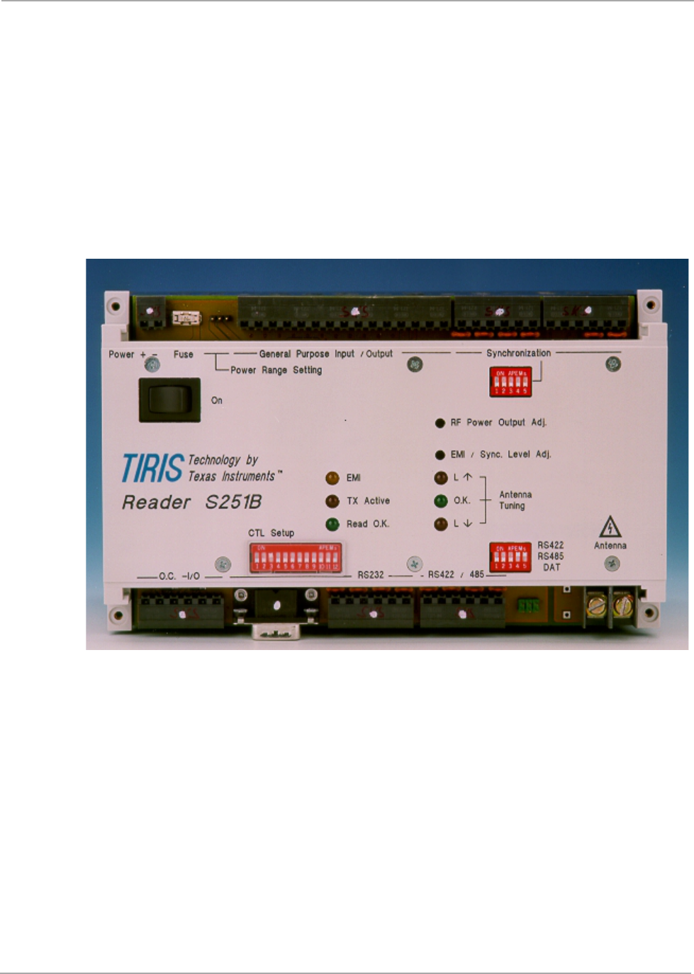
The reader is shown in Figure 1 and the front panel is shown in Figure 2.
Figure 2: S251B Front Panel (with connector covers removed)
The reader comprises two modules assembled together in a housing. The modules
are:
Control Module which contains all the circuitry required to communicate via the
interface to the computer and external devices, to provide syn-
chronization, and to control the RFM. It includes a Dynamic Auto
Tuning (DAT) function to automatically tune the antenna to reso-
nance.
Radio Frequency Module (RFM) which contains all the analog functions of a TI-
RIS reading unit that are needed to initialize a TIRIS transponder
and to detect its return signal.
11
April ’00 Chapter 2. Hardware
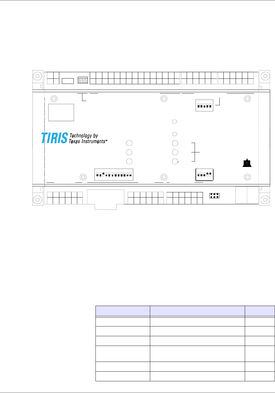
2.2.1 Connectors
There are 10 connectors on the S251B, 7 WECO connectors, the antenna connector,
a 9-pin sub-D RS232 connector, a 6-pin connector for the indicator outputs and a 2-
pin connector for the antenna. The function of each pin on each connector (except
the RS232 sub-D connector) is described in the following paragraphs. Their location
is shown in Figure 3.
Figure 3: S251B Connector Locations
In order to gain access to the fuse and connector J you must first remove the upper
two screws holding the front panel on, remove the plastic cover strip and then replace
the two screws. To gain access to the connectors H and I you must first remove the
lower two screws holding the front panel on, remove the plastic cover strip and then
replace the two screws.
The pins are not individually numbered on the connectors themselves (just on Figure
3 for your convenience).
The connectors are all marked on Figure 3 with a letter (from A to I) and are listed in
Table 1 which also shows the section that describes them
Table 1: List of Connectors
Identifying Letter Function Section
A Supply Connector 2.2.1.1
B General Purpose Inputs/Outputs 2.2.1.2
C Synchronization Interface 2.2.1.3
DCarrier Phase Synchronization
Interface 2.2.1.4
E Open Collector Inputs/Outputs 2.2.1.5
F1 RS232 Connector (9-pin SEB-D) 2.2.1.6
General Purpose Input / Output
Antenna
Power Fuse Synchronization
+ -
RS422 / 485
RS232
CTL Setup
O.C. - I/O
Read O.K.
TX Active
EMI
Antenna
Tuning
O.K.
L !
RS422
RS485
DAT
L "
RF Power Output Adj.
EMI / Sync. Level Adj.
On
Reader S251B
Power Range Setting
12
A
115
B
16
C
16
D
16
G
16
F2
16
EF1 H
12
I
1 1
1
On
On On
J
123
12
S2510 Reader - Reference Guide April ’00
2.2.1.1 A - Supply Connector
The Reader requires a single DC supply voltage (10 to 24 V) through a 2-pin connec-
tor marked with + for positive and – for negative
The Power Range Setting wired jumpers (marked J in Figure 3) and the actual power
supply have a direct consequence on the operating temperature of the reader as
shown in Table 2.
1..
F2 RS232 Connector 2.2.1.6
G RS422/RS485 Connector 2.2.1.7
H Indicator Outputs 2.2.1.8
I Antenna Connector 2.2.1.9
Table 2: Power Range Settings
Setting Input Power Operating Temperature Range
Pins 1 + 2 connected 10 - 15 V -20º to +70º C
“ 15 - 24 V -20º to +70º C
(max. I_VSP = 0.9 Apeak see caution 1).
Pins 2 + 3 connected 18 - 24 V -20º to +70º C
CAUTION:
1. In order to operate the reader over the full temperature range
with pins 1 + 2 connected (15 to 24 V), the maximum current
consumption must not exceed 0.9 Apeak. Exceeding this
value could result in unreliable functioning of the dynamic
auto tuning, or sharp limitation of the transmitter output
power because of internal protection. If either of these should
occur, switch the device off and allow it time to recover; and
then when it is switched on again it will revert to normal oper-
ation. Note that if either of these occur it is an indication that
the reader is not being operated within its specifications.
2. The reader itself generates heat, therefore if it is incorporated
into a housing you must ensure (by proper design and/or
cooling) that the temperature immediately surrounding the
reader does not exceed the operating temperature range.
Table 3: Supply Connector
Pin Signal Description Direction
1 + Positive supply input
2 - Ground input
Table 1: List of Connectors
Identifying Letter Function Section

13
April ’00 Chapter 2. Hardware
2.2.1.2 B - General Purpose Inputs/Outputs
The Reader has eight general purpose TTL-Level Inputs/Outputs. By means of the
configuration set-up, they can be set in groups of four to be Input or Output. Further-
more, there is a reset connection and a 5 V regulated output.
The pin assignment is given in Table 5 and their specifications are given in Table 6.
Table 4: Supply Connector - Specifications
Parameter Minimum Maximum
Logic Supply Voltage VSL 10 V 24 V
Logic Supply current ISL - 2.5 A
Table 5: General Purpose Inputs/Outputs
Pin Signal Description Direction
1 GP IO 7 General Purpose I/O 7 Input/Output
2 GP IO 6 General Purpose I/O 6 Input/Output
3 GP IO 5 General Purpose I/O 5 Input/Output
4 GP IO 4 General Purpose I/O 4 Input/Output
5 GP IO 3 General Purpose I/O 3 Input/Output
6 GP IO 2 General Purpose I/O 2 Input/Output
7 GP IO 1 General Purpose I/O 1 Input/Output
8 GP IO 0 General Purpose I/O 0 Input/Output
9 - not connected -
10 IN1 Input 1 Input
11 IN0 Input 0 Input
12 RESET- Reset Input
13 VCC Regulated 5 Volt dc Supply
(see note) Output
14 GND Signal Ground -
15 GND Signal Ground -
CAUTION:
Do not connect any power supply to pin 13 as it would
damage the reader.
The total consumption of the two VCC outputs (General
Purpose Inputs/Outputs pin 13 together with Open Collec-
tor & I/Os - pin 1) must not exceed 500 mA.

14
S2510 Reader - Reference Guide April ’00
2.2.1.3 C - Synchronization Interface
The synchronization interface is used to establish hard wired synchronization with
other readers through a single or double pair of wires. Its pin assignment is given in
Table 7 and its specifications are given in Table 8.
Table 6: General Purpose Inputs/Outputs - Specifications
Parameter Minimum Maximum
GP IO Output Voltage @ 6 mA
Low level
High level -
3.15 V 0.9 V
5.25 V
General Purpose IO Output Current
Low level
High level -
-
25 mA
16 mA
GP IO 1 to 4 total Output Current 10 mA
GP IO 5 to 8 total Output Current 10 mA
Regulated 5 V Output Current 100 mA
Table 7: Synchronization Interface
Pin Signal Description Direction
1 Sync Rx+ RS422/RS485 non-inverted synchronization data Input
2 Sync Rx- RS422/RS485 inverted synchronization data Input
3 GND Signal ground -
4 Sync Tx+ RS422/RS485 non-inverted synchronization data Output
5 Sync Tx- RS422/RS485 inverted synchronization data Output
6 GND Signal ground -
Table 8: Synchronization Interface - Specifications
Parameter Specification
Mode of Operation Differential
Number of Drivers On Line 32
Number of Receivers On Line 32
Maximum Cable Length 1200 m
Maximum Data Rate 10 Mbits/s
Maximum Common Mode Voltage +12 V / -7 V
Driver Voltage High > +1.5 V
Low < -1.5 V
Driver Load 60 mA
Driver Output Short Circuit Limit 150mA to GND
250mA to VCC

15
April ’00 Chapter 2. Hardware
2.2.1.4 D - Carrier Phase Synchronization Interface
The carrier phase synchronization interface is used to establish hard wired carrier
phase synchronization with other readers through a single pair of wires. Its pin as-
signment is given in Table 9 and its specifications are given in Table 10.
Receiver Input 12 kΩ
Receiver Sensitivity ±200 mV
Receiver Hysteresis 60 mV
Table 9: Carrier Phase Synchronization Interface
Pin Signal Description Direction
1 Sync Rx+ RS422/RS485 non-inverted synchronization data Input
2 Sync Rx- RS422/RS485 inverted synchronization data Input
3 GND Signal ground -
4 Sync Tx+ RS422/RS485 non-inverted synchronization data Output
5 Sync Tx- RS422/RS485 inverted synchronization data Output
6 GND Signal ground -
Table 10: CPS Interface - Specifications
Parameter Specification
Mode of Operation Differential
Number of Drivers On Line 32
Number of Receivers On Line 32
Maximum Cable Length 1200 m
Maximum Data Rate 10 Mbits/s
Maximum Common Mode Voltage +12 V / -7 V
Driver Voltage High > +1.5 V
Low < -1.5 V
Driver Load 60 mA
Driver Output Short Circuit Limit 150mA to GND
250mA to VCC
Receiver Input 12 kΩ
Receiver Sensitivity ±200 mV
Receiver Hysteresis 60 mV
Table 8: Synchronization Interface - Specifications
Parameter Specification
16
S2510 Reader - Reference Guide April ’00
2.2.1.5 E - Open Collector & I/Os
This connector provide two open collector connections to and from the reader, plus
the RXSS output (used to set the local noise level), another 5 V regulated output and
an interrupt input. Its pin assignment is given in Table 11 and its specifications are
given in Table 12.
Table 11: Open Collector & I/Os
Pin Signal Description Direction
1 VCC Regulated 5 Volt dc Supply (see note 1 below) Output
2 OC1 Open collector 1 Output
3 OC0 Open collector 0 Output
4 GND Signal ground -
5 INT0 Interrupt 0 (see note 2 below:) Input
6 RXSS- RXSS Output
Notes:
1. The total consumption of the two VCC outputs (Open Collector & I/
Os - pin 1 together with General Purpose Inputs/Outputs pin 13)
must not exceed 500 mA.
2. This function is not used or supported by TIRIS standard firmware.
It can however be used, if required, by customers who are provid-
ing their own software.
Table 12: Open Collector & I/Os - Specifications
Parameter Minimum Maximum
Open Collector Voltage to GND 1.3 V 80 V
Open Collector Current 500 mA
Regulated 5 V Output 4.75 V 5.25 V
Interrupt Input 4.75 V 5.25 V
RXSS - 5.25 V

17
April ’00 Chapter 2. Hardware
2.2.1.6 F1 & F2 - RS232 Communication Interface
Depending on the DIP-Switch configuration, the Reader will either communicate via
the RS232, RS422 or RS485 interface.
There are two interface connectors either of which can be used for an RS232C con-
nection. They are: a standard RS232 Interface 9-pin SUB-D male connector (F1 on
Figure 3) and a 6-pin WECO connector (F2 on Figure 3). Both of these connectors
allow communication between the reader and a controlling device. The pin assign-
ment for the SUB-D connector is given in Table 13 and the pin assignment for the
WECO connector is given in Table 14.
Both, the ASCII and TIRIS Bus protocol can be used with the RS232 interface.
All interface parameters are according to the RS232 specification and are not given
in detail in this manual. The DTR and DSR lines are currently not used for any pur-
pose.
Table 13: RS232 SUB-D Connector
Pin Signal Description Direction
1 - Not connected -
2 TxD Transmit Data Output
3 RxD Receive Data Input
4 DTR Data Terminal Ready Input
5 GND Signal Ground -
6 DSR Data Set Ready Output
7 - Not connected -
8 - Not connected -
9 - Not connected -
Table 14: RS232 WECO Connector
Pin Signal Description Direction
1 RxD Receive Data Input
2 DTR Data Terminal Ready Input
3 GND Signal Ground -
4 TxD Transmit Data Output
5 DSR Data Set Ready Output
6 GND Signal Ground -

18
S2510 Reader - Reference Guide April ’00
2.2.1.7 G - RS422/RS485 Communications Interface
Depending on the DIP-Switch configuration, the Reader will communicate via the
RS232, RS422 or RS485 interface. RS422/485 connections are made via the 6-pin
WECO connector (G in Figure 3). Its pin assignment is given in Table 15 and its spec-
ifications are given in Table 16.
Both, the ASCII and TIRIS Bus Protocol can be used with the RS422 interface.
The ASCII protocol (or any other full-duplex protocol) cannot be used with the RS485
interface.
Table 15: RS422/RS485 Connector
Pin Signal Description Direction
RS422 Direction
RS485
1Rx+/Tx+
RS422/RS485 non-
inverted data Input Input/Output
2 Rx-/Tx- RS422/RS485
inverted data Input Input/Output
3 GND Signal Ground - -
4Tx+
RS422 non-inverted
data Output/High
Impedance -
5 Tx- RS422 inverted data Output/High
Impedance -
6 GND Signal Ground - -
Table 16: RS422/RS485 Communications Interface - Specifications
Parameter Specification
Mode of Operation Differential
Number of Drivers On Line 32
Number of Receivers On Line 32
Maximum Cable Length 1200 m
Maximum Data Rate 10 Mbits/s
Maximum Common Mode Voltage +12 V / -7 V
Driver Voltage High > +1.5 V
Low < -1.5 V
Driver Load 60 mA
Driver Output Short Circuit Limit 150mA to GND
250mA to VCC
Receiver Input 12 kΩ
Receiver Sensitivity ±200 mV
Receiver Hysteresis 60 mV

19
April ’00 Chapter 2. Hardware
2.2.1.8 H - Indicator Outputs
This connector (H in Figure 3) is a 2 x 3-pin (double row) pin header connection which
provides the LED output signals. Its pin assignment is given in Table 17 and its spec-
ifications are given in Table 18.
2.2.1.9 I - Antenna Connector
The antenna must be connected to the reader via the antenna terminals. The pin as-
signment for the antenna connector is given in Table 19. If a custom designed anten-
na is used, it must be within the specifications defined in Table 20 in order to ensure
that the dynamic autotuning facility functions correctly.
Table 17: Indicator Outputs
Pin Signal Description Direction
1 ACTIVE Open collector output: RF Module transmitter signal Output
2VR270 Current limited output: (270 Ω in series to VCC) Output
3 O.K. Open collector output: O.K. signal Output
4VR270 Current limited output (270 Ω in series to VCC) Output
5 RXSA Receiver signal strength adjust output to monitor the
receiver signal strength threshold level Output
6 GND Signal ground -
Table 18: Indicator Outputs - Specifications
Parameter Minimum Maximum
Open Collector (voltage) - 10 V
Open Collector (current) - 80 mA
Maximum voltage at current limiting 270 Ω resistor - 5 V
Receiver signal strength output voltage (RXSA) 0.7 V 1.7 V
Table 19: Antenna
Pin Signal Description
1 ANT Tx/Rx antenna
2 ANT Tx/Rx antenna
Table 20: Antenna - Specifications
Parameter Minimum Maximum
Antenna Resonance Voltage - 380 Vpeak
Antenna Inductance 26.0 µH 27.9 µH
Antenna Q-factor 40 350
20
S2510 Reader - Reference Guide April ’00
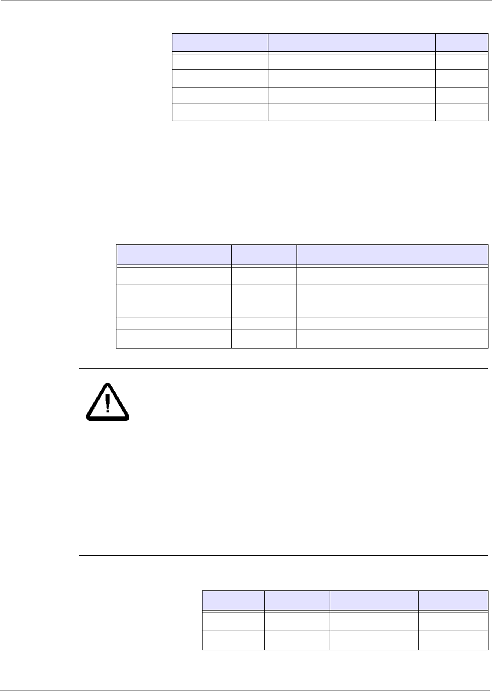
2.2.2 Switches
There are three banks of DIP switches on the S251B Reader, one is for the Control
Module set-up (12 switches), one is for the RS422/RS485/DAT settings (5 switches),
and the third one is for the synchronization settings (5 switches). The Control Module
set-up switches are listed in Table 21, the RS422/RS485/DAT settings are listed in
Table 23, and the synchronization settings switches are listed in Table 24. The ON
position and switch 1 are always shown in the switch bank, the switch is on when the
switch is set to the up position.
Figure 4: CTL Setup Switches
* When this switch (11) is switched either from ON-to-OFF or from OFF-to-
ON the reader’s transmitter is activated for 10 seconds.
Table 21: CTL Setup DIP Switches
Switch OFF ON
1 RAM - VCC -
2Chip Select ROM for TIRIS
Standard Firmware Reserved for Software Development
3 Reserved for Software Development Chip Select RAM for TIRIS Standard
Firmware
4Chip Select RAM for TIRIS Standard
Firmware Reserved for Software Development
5 PSEN Reserved for Software Development
6 See Table 22
7 See Table 22
8 TIRIS Standard Configuration Customer Specific Configuration
9 Reserved
10 Reserved
11 TXCT-ON *
12 Not Connected
Table 22: I/O Setting Switches (6 & 7)
SW6 SW7 Comment
OFF OFF No effect
ON ON/OFF Reset reader by switching RS232 DTR line
OFF ON Can be used by customer firmware for hardware handshake
ON
1
21
April ’00 Chapter 2. Hardware
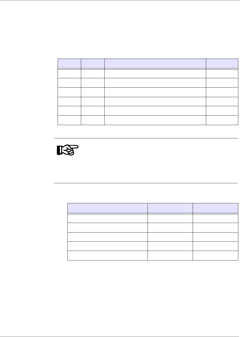
Figure 5: RS422/RS485/DAT Switches
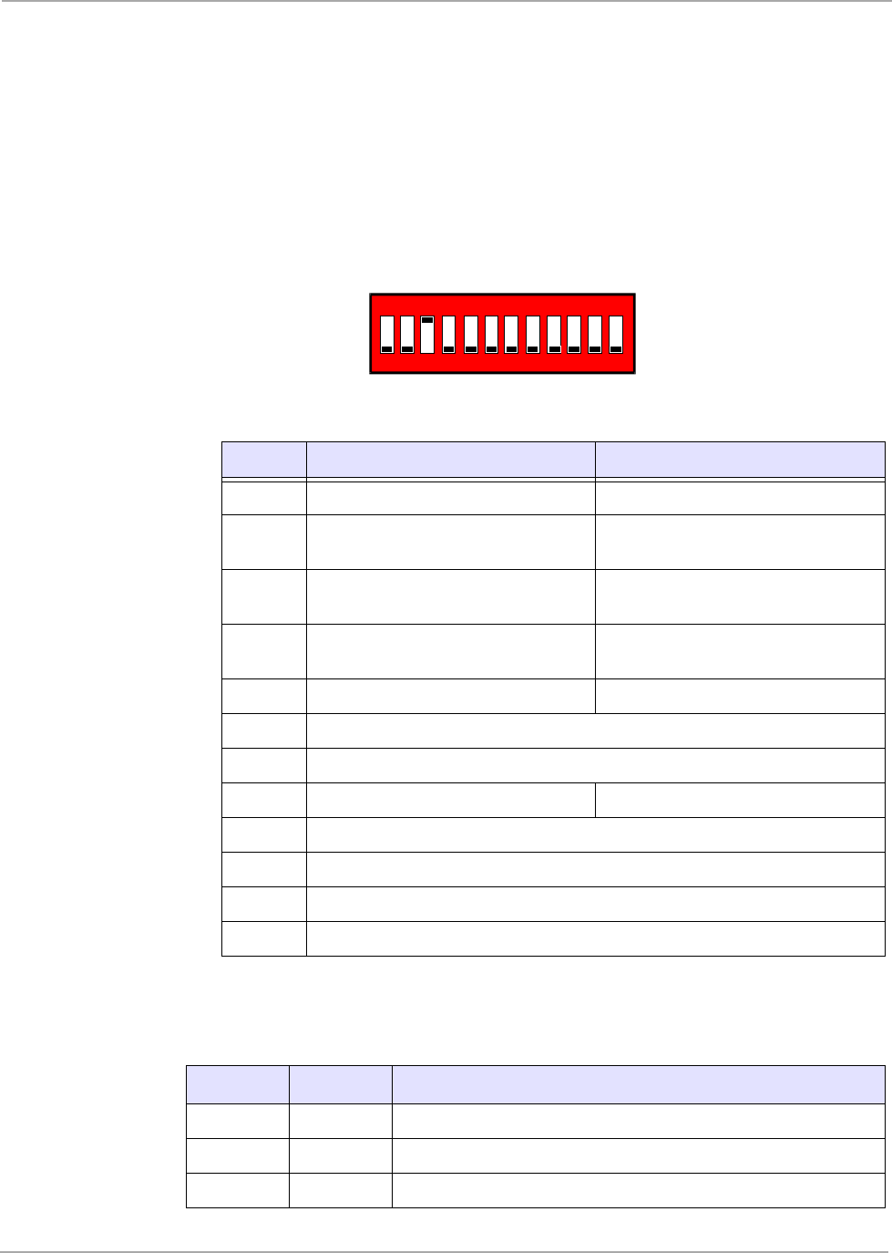
Figure 6: Synchronization DIP Switches
Table 23: RS422/RS485/DAT Settings DIP Switches
Switch OFF ON
1 RS422 RS485
2 RS422 RS485
3- RS422/RS485 Rx+/Rx-
line-to-line termination (120 Ω)
4 DAT Disabled DAT Enabled
5 DAT LEDs Disabled DAT LEDs Enabled
Notes:
SW1 and SW2 must always be in the same position as each other,
either both OFF or both ON.
Table 24: Synchronization DIP Switches
Switch OFF ON
1 - Synchronization Rx+ line pull-up (180 Ω)
2 - Synchronization Rx- line pull-down (180 Ω)
3- RS422/RS485 Rx+/Rx- line-to-line
termination (120 Ω)
4 Set the RFM to Master Set the RFM to Slave in CPS Bus
5 - CPS line-to-line termination (120 Ω)
ON
1
ON
1

22
S2510 Reader - Reference Guide April ’00
2.2.3 Indicators
There are six LEDs on the front panel of the reader they are described in Table 25.
The TX Active and Read O.K. LED lines are also made available for external use if
required, details are given in section 4.7.
2.2.4 Potentiometers
There are two potentiometers that can be adjusted through the reader front panel,
they are: the RF Power Output adjustment potentiometer (2.2.4.1) and the EMI /
Sync. Level adjustment potentiometer (2.2.4.2).
2.2.4.1 RF Power Adjustment
The potentiometer can be used to adjust the internal oscillator pulse width and thus
the generated antenna voltage/field strength. Turning the potentiometer clockwise
causes the field strength to be increased.
2.2.4.2 EMI / Sync. Level Adjustment
This potentiometer allows the receiver signal strength threshold level to be adjusted
for wireless synchronization. Turning the potentiometer clockwise results in maxi-
mum sensitivity.
There is one fuse on the S251B that is: 2A Slow-blow. If the fuse should blow, replace
it with the replacement fuse supplied with your reader.
2.3 Mechanical Information
The mechanical dimensions and weight are given in Table 26.
Table 25: Indicators
Indicator Description
EMI Indicates the presence of Electro Magnetic interference
TX Active Indicates activation of the RF transmitter
Read O.K. Indicates a response from a valid transponder
Antenna
Tuning
L ↑Antenna out of tune, inductance too high
O.K. The DAT has tuned the antenna to maximum resonance voltage
L ↓Antenna out of tune, inductance too low
Table 26: Mechanical Information
Parameter Value
Height 120 mm
Width 120 mm
Length 200mm
Weight 900 g

CHAPTER 3
23
Synchronization
Chapter 3:Synchronization
If you are using more than one reader in an application, it may mean that you need
to synchronize their operation so that they do not interfere with each other. This
chapter describes the various synchronization options.
Topic Page
3.1 Introduction ................................................................................................24
3.2 Types of Synchronization .........................................................................24
3.2.1 No Synchronization ..............................................................................24
3.2.2 Wireless Synchronization.....................................................................25
3.2.3 Wired Synchronization .........................................................................25
3.2.4 Combined Wireless/Wired Synchronization .........................................25
3.2.5 Master/Slave Synchronization..............................................................26
3.2.5.1 M/S Synchronization without Acknowledgement........................26
3.2.5.2 M/S Synchronization with Acknowledgement. ............................26
3.2.5.3 Triggered Synchronization..........................................................27
3.2.6 Carrier Phase Synchronization ............................................................27

24
S2510 Reader - Reference Guide April ’00
3.1 Introduction
Where multiple readers are operating in the same area, it is necessary to coordinate
the activities of those readers to avoid mutual interference. This is known as synchro-
nization. Synchronization in this context means that the readers in your application
are controlled in such a way that they do not interfere with each other.
There are several types of synchronization that can be used depending on the situ-
ation in a particular application, for example: the type of transponder, the type of op-
eration performed on that transponder (Charge-only read, General read, Program
page, Lock page), the size of the antennas and the speed of the transponder. The
different kinds of synchronization are described in section 3.2. How to actually set-
up your system to use the synchronization you’ve chosen is described together with
the other installation procedures in Chapter 5.
The distance that readers’ antennas have to be separated before the need for some
method of synchronization is required, varies with local conditions, for in addition to
purely airborne (radiated) interference, signals can travel from one reader to another
via metal structures (conducted). Metal structures can include the frames of metal
buildings, reinforcing bars in concrete floors and power or data cables.
3.2 Types of Synchronization
The S251B Reader can be configured to synchronize in a number of different ways:
No Synchronization (3.2.1)
Wireless Synchronization (3.2.2)
Wired (3.2.3)
Combined Wireless/Wired (3.2.4)
Master/Slave Synchronization (3.2.5)
Carrier Phase Synchronization (3.2.6)
3.2.1 No Synchronization
This option is only used in conjunction with Software synchronization, or if there is
only a single reader. No sync. and Master/Slave sync without acknowledgement are
the fastest methods of reading transponders.
If all readers are connected by the same RS485 data network, coordination of the
readers can be controlled directly by the Host Computer. For example, the Host
Computer may issue a Broadcast command for all readers to simultaneously perform
a read cycle and buffer the result. Another technique possible using the data network
is to issue individual commands to each reader in turn. This technique is used when
writing data to Multipage Transponders (MPTs). Where a PLC has a number of
point-to-point connections to readers, it is also possible to coordinate the activities
via the ladder logic. With Software synchronization all readers will be simultaneously
transmitting or, each reader individually operating. In both cases the readers can be
configured to have No Synchronization.

25
April ’00 Chapter 3. Synchronization
3.2.2 Wireless Synchronization
Wireless synchronization can be used to control the coordination of readers, with
standard antennas, provided the electrical noise in the environment is low for the
type of antenna in use and the noise levels are constant.
Wireless synchronization is only valid for charge-only reading of transponders.
During operation, when the reader detects noise above the adjusted background lev-
el it assumes that it is another reader and “backs-off” for a set period before com-
mencing its own cycle. Wireless synchronized readers can read together or
alternately.
Advantages:
1. There are no wires to run.
2. All readers are autonomous (no Master unit).
3. Enables Hand held readers to co-exist with fixed units (using wireless syn-
chronization).
Disadvantages:
1. In noisy environments, there is too much sensitivity with larger antennas
(G04 and larger custom antennas) to allow accurate setting of the back-
ground levels.
2. It is not suitable for operations other than Charge-only read.
3. It cannot be used when other readers are writing information to transpond-
ers.
4. Where the environmental conditions change, for example: a ground loop
antenna’s characteristics are changed by a vehicle over it, the synchroni-
zation adjustment could be wrong.
3.2.3 Wired Synchronization
Wired Synchronization works in the same way as wireless synchronization with the
exception that the reader obtains its information about the presence of another read-
er through a hard wired connection and not via the antenna.
Advantages:
1. It is a Peer-to-Peer network and does not need a Master unit.
2. It use a single twisted pair cable.
Disadvantages:
1. It is only suitable for charge-only reading of transponders.
2. It cannot be used when other readers are writing information to transpond-
ers.
3. If the power fails at any of the readers the bus fails.
3.2.4 Combined Wireless/Wired Synchronization
When this option is selected, groups of reader connected by the wired synchroniza-
tion cabling can synchronize with other groups of wired synchronization readers, or
with individual readers, by using wireless synchronization.
The advantages and disadvantages of both wireless and wired synchronization as
given above still apply.

26
S2510 Reader - Reference Guide April ’00
3.2.5 Master/Slave Synchronization
Master/Slave Synchronization is probably the most commonly used form of synchro-
nization. One reader is configured to be the Master and this reader then controls all
the other readers, which are configured as Slaves.
There are three variants:
Master/Slave Synchronization without Acknowledgement,
Master/Slave Synchronization with Acknowledgement
Triggered Synchronization.
3.2.5.1 M/S Synchronization without Acknowledgement.
This method of synchronization is the fastest method of reading transponders and
was originally developed for reading tagged vehicles at speed. It assumes that all
readers are on the same synchronization bus and the readers would not, for exam-
ple, recognise a handheld reader that is trying (probably unsuccessfully) to perform
a reading.
Advantages:
1. Uses a single twisted pair cable.
2. Has the fastest read rate.
3. The Master can be used for Charge-only read or Write/Program.
Disadvantages:
1. All readers must be on the same synchronization bus.
2. If the Master fails, all units stop.
3. Slave units cannot be individually tested without the Master running.
4. Slaves must perform exactly the same RF-Task as the Master (read the
same page, write the same data to a transponder).
3.2.5.2 M/S Synchronization with Acknowledgement.
In Master/Slave Synchronization without acknowledgement, if a slave reads a trans-
ponder and the master doesn’t, the slave may miss the next pulse while it is process-
ing the reading from that transponder. In Master/Slave with Acknowledgement the
Master has to wait until all slaves have completed their current cycle before initiating
the next cycle. This is achieved by using a 4 wire synchronization bus (twin twisted
pair) with the slave transmit lines coupled back to the Master receive lines.
This method has the following advantages over Master/Slave without Acknowledge
1. All units can Write/Program transponders (providing they do it together).
2. They wait for the slowest to complete.
Disadvantages:
1. The cable is a twin twisted pair.
2. The readers cannot be too close if writing is performed, because of the pos-
sibility of corrupted data. This restriction also includes the paged read of
multipage transponders.

27
April ’00 Chapter 3. Synchronization
3.2.5.3 Triggered Synchronization
Triggered Synchronization is a Master/Slave Synchronization Bus where there is just
a pulse signal. All readers are configured as masters, but it is only one unit or a trig-
ger pulse source that issues the synchronization pulse at suitable intervals for the re-
quired operations on the transponder.
The more complex version of this is known as a Timing Bus, when different time win-
dows are defined for different operations to be carried out, for example: If multiple
readers are required to read addressed pages of Multipage transponders, then to
write data back to the transponders, the timing bus would start a read window lasting
90 ms then initiate a time window of 320 ms for a write operation. In this way the dif-
fering times required for the two operations can be accommodated. At the same time
the readers would be instructed thru the communication interface, about which com-
mand to execute during each window. Therefore the slaves have to receive their
command before the master.
Advantages:
1. The master unit has total control over the coordination of the connected de-
vices and can allow ‘windows’ for particular operations.
2. Reading and Writing can be accommodated, if there is sufficient separation
to prevent data corruption during the Write process.
Disadvantages:
1. Cannot be used for addressing MP transponders if readers are close to-
gether as addressing conflicts can arise.
2. Carrier Phase synchronization cannot be used.
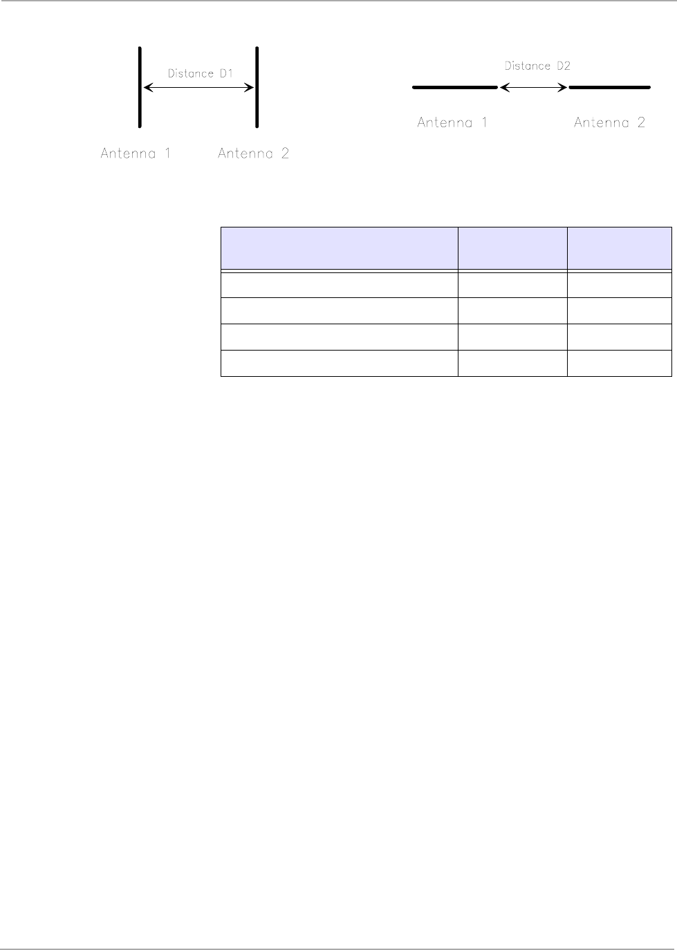
3.2.6 Carrier Phase Synchronization
In some applications it is necessary to use several charge-up antennas close to each
other. In these circumstance, the magnetic charge-up fields generated by different
antennas superimpose on each other and may cause a beat effect on the magnetic
charge-up field, due to the slightly different transmission phases of different Power
readers. This effect will not occur when the transmitters of different readers are op-
erated from the same oscillator signal.
This is Carrier Phase Synchronization where all of the readers in a system use the
same oscillator. Carrier Phase synchronization must be used whenever Gate or Stick
antennas are facing each other and if they are inside the distances D1 or D2 as given
in Table 27 (Figure 7 shows the places to measure D1 and D2). This ensures that
there will not be any “beat effect” between the antennas.
Note:
Remember that putting two antennas close together also changes
antenna inductance, so that the antennas may no longer be tuneable
to resonance.
28
S2510 Reader - Reference Guide April ’00
Figure 7: Distance between Antennas (top view)
Table 27: Distances Between Antennas
Antenna type Distance D1
[m] Distance D2
[m]
RI_ANT_S02 <=> RI_ANT_S02 0.8 1.0
RI_ANT_G01 <=> RI_ANT_G01 1.7 1.5
RI_ANT_G02 <=> RI_ANT_G02 1.3 1.0
RI_ANT_G04 <=> RI_ANT_G04 2.0 1.7

CHAPTER 4
29
Installation
Chapter 4:Installation
This chapter provides you with the information that you need to know in order to in-
stall the reader.
This chapter also describes how to incorporate the various synchronization options.
Topic Page
4.1 Introduction ................................................................................................30
4.2 General........................................................................................................30
4.3 Mechanical Mounting.................................................................................30
4.3.1 Power Supply .......................................................................................30
4.4 Communication..........................................................................................31
4.4.1 Configuration........................................................................................31
4.4.2 RS232 ..................................................................................................31
4.4.2.1 Activation ....................................................................................32
4.4.3 RS422 ..................................................................................................32
4.4.4 RS485 ..................................................................................................33
4.5 Synchronization .........................................................................................34
4.5.1 Software Controlled..............................................................................34
4.5.2 Wireless Synchronization.....................................................................34
4.5.3 Wired and Combined Wireless/Wired Synchronization........................34
4.5.4 Master/Slave (without acknowledgement) & Triggered Synch.............35
4.5.5 Master/Slave (with acknowledgement) ................................................36
4.5.6 Transmitter Carrier Phase Synchronisation (CPS) ..............................37
4.6 General Purpose Input/Outputs................................................................38
4.7 LED Outputs ...............................................................................................39
4.8 Reset ...........................................................................................................39
4.9 Antenna.......................................................................................................40
4.10 RF Power Output Adjustment...................................................................40
4.11 EMI / Sync. Level Adjustment ...................................................................40
30
S2510 Reader - Reference Guide April ’00
4.1 Introduction
4.2 General
The S251B Reader has been designed with easy installation in mind. The following
information provides you with any details such as switch settings and so on that you
will need to know.
4.3 Mechanical Mounting
a. If you are mounting the reader on a DIN rail TS35, clip the reader into the bot-
tom of the rail and then snap it into the top.
or
b. If you are mounting the reader onto a wall where there is No vibration, snap in
the four mounting adapters and screw the reader to the wall using M4 screws.
or
c. If you are mounting it onto a wall where it may be subject to vibration, open the
reader, drill thru the marked mounting holes and screw the reader to the wall
using M4 screws and the appropriate washers.
4.3.1 Power Supply
Connect a Regulated dc power supply (between 10 and 24 V providing a minimum
of 2A) to the reader - the polarity of the connection is shown on the front panel of the
reader.
Set the Power Range Setting wire bridge to match your input voltage (see Table 2).
We recommend that you use a linear power supply. If this is not possible and you
wish to use a switched mode power supply, DO NOT use one that operates below
200 kHz. (switched mode power supplies that operate below 200 kHz. might interfere
with transponder signals and thus reduce the reading range).
Note:
Always ensure that the reader is switched off when making or break-
ing connections to it.
WARNING:
CARE MUST BE TAKEN WHEN HANDLING THE S251B. HIGH
VOLTAGE ACROSS THE ANTENNA TERMINALS COULD BE
HARMFUL TO YOUR HEALTH. IF THE ANTENNA INSULATION IS
DAMAGED THE ANTENNA SHOULD NOT BE CONNECTED TO THE
S251B.
31
April ’00 Chapter 4. Installation
4.4 Communication
Follow the instructions given in the section that describes the communications set-
up that you have decided to use in your system: Section 4.4.2 for RS232, Section
4.4.3 for RS422 and Section 4.4.4 for RS485.
4.4.1 Configuration
CTL Setup switch 8 determines the mode of operation of the control module when
power is applied to the control module. When CTL Setup switch 8 is in the OFF po-
sition, standard TIRIS default parameters are used, these are:
- ASCII protocol
- 9600 baud, eight databits, no parity, one stop bit, Xon/Xoff enabled
- Normal Mode
- Wireless synchronization
- I/O 0 to 3 defined as input
- I/O 4 to 7 defined as output and logic high
- Hardware interface RS232C
If CTL Setup switch 8 is in the ON position, customer specific parameters are used
to operate the Control Module. These application specific parameters are stored in
the serial EEPROM on the Control Module.
You can use the Software Utility Program which is available on the internet at our
site: http://www.tiris.com to configure your reader.
In order to configure the reader for customer specific parameters you must connect
the reader via the RS232 port (connector F1 or F2) to your host and get connection
using the TIRIS standard parameters (with CTL Setup switch 8 is in the OFF posi-
tion). Change the default parameters to the customer specific parameters and save
them. Set CTL Setup switch 8 to the ON position and reset the reader. The reader
will then work with the customer specific parameters.
4.4.2 RS232
Either connect a 9-pin SUB-D female plug to the SUB-D connector, or connect up the
6-pin WECO connector marked “RS232” on the reader’s front panel, the pin signals
are given in Table 28 or Table 29.
Note:
The setting of CTL Setup switch 8 is only checked after power on.
Table 28: RS232 9-pin Connector
Pin Signal Description Direction
1 - Not connected -
2 TxD Transmit Data Output
3 RxD Receive Data Input
4 DTR Data Terminal Ready Input

32
S2510 Reader - Reference Guide April ’00
4.4.2.1 Activation
The Data Terminal Ready signal (DTR) is connected to the reset/watchdog circuit of
the S251B Reader. This ensures a PC controlled microcomputer initialization before
the default Read Mode is started.
When power is applied to the reader the Data Set Ready signal (DSR) of the RS232-
C interface is activated.
4.4.3 RS422
Connect the WECO (marked RS422 / 485) connector as shown in Table 30. Set the
switches as shown in Figure 8. If you are only using one reader the line terminal
switch 3 must be switched to ON, if you are using more than one reader only the last
reader in the line must be switched to ON (all other readers to OFF).
5 GND Signal Ground -
6 DSR Data Set Ready Output
7 - Not connected -
8 - Not connected -
9 - Not connected -
Table 29: RS232 WECO Connector
Pin Signal Description Direction
1 RxD Receive Data Input
2 DTR Data Terminal Ready Input
3 GND Signal Ground -
4 TxD Transmit Data Output
5 DSR Data Set Ready Output
6 GND Signal Ground -
Table 28: RS232 9-pin Connector
Pin Signal Description Direction
33
April ’00 Chapter 4. Installation
Figure 8: Switch Settings for RS422
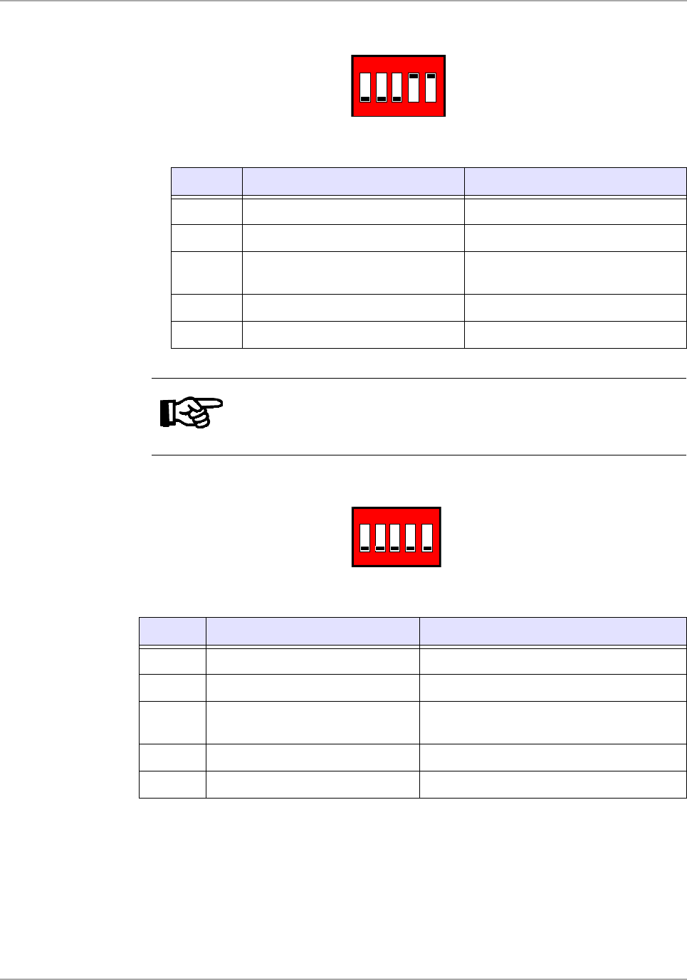
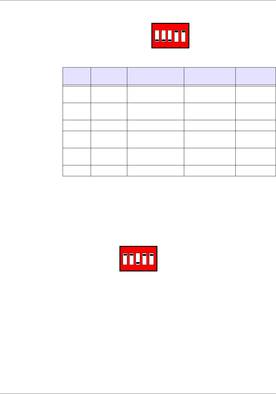
4.4.4 RS485
Connect the WECO (marked RS422 / 485) connector as shown in Table 30. Set the
switches as shown in Figure 9. If you are only using one reader the line terminal
switch 3 must be switched to ON, if you are using more than one reader only the last
reader in the line must be switched to ON (all other readers to OFF).
Figure 9: Switch Settings for RS485
Table 30: RS422/RS485 Connector
Pin Signal Description Direction
RS422 Direction
RS485
1Rx+/Tx+
RS422/RS485 non-
inverted data Input Input/Output
2 Rx-/Tx- RS422/RS485
inverted data Input Input/Output
3 GND Signal Ground - -
4Tx+
RS422 non-inverted
data Output/High
Impedance -
5 Tx- RS422 inverted data Output/High
Impedance -
6 GND Signal Ground - -
ON
1
ON
1
34
S2510 Reader - Reference Guide April ’00
4.5 Synchronization
4.5.1 Software Controlled
There is no special wiring required for this type of synchronization. Make sure that
you set the software configuration to No Sync. when you are configuring the reader.
4.5.2 Wireless Synchronization
There are no switch or jumper settings for wireless synchronization. Make sure that
you set the software configuration to wireless synchronization when you are config-
uring the reader.
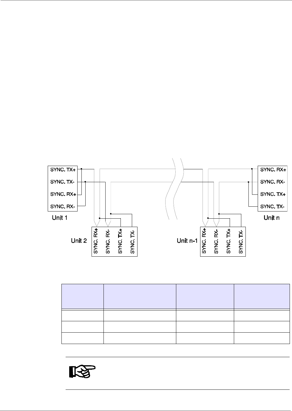
4.5.3 Wired and Combined Wireless/Wired Synchronization
Figure 10 shows in which way the S251B Reader must be connected for a wired and
a combined wireless/wired synchronization. Make sure that you set the software con-
figuration to match when you are configuring the reader. Table 31 explains the set-
ting of the Synchronization DIP switches 1, 2 & 3.
Figure 10: Wired & Combined Wireless/Wired Sync. Interface Connection
Table 31: Wired and Combined Wireless/Wired Synchronization
Line
Termination
Dip Switch UNIT 1: UNIT 2...UNIT n-1: UNIT n:
SW1 ON OFF ON
SW2 ON OFF ON
SW3 ON OFF ON (see Note)
Note:
If the distance between Unit 1 and Unit n is less than approximately
400 m, DIP switch SW3 can be left OFF.
35
April ’00 Chapter 4. Installation
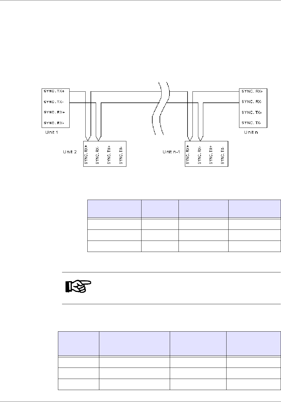
4.5.4 Master/Slave (without acknowledgement) & Triggered Synch.
Figure 11 shows the way that the Readers have to be connected for master/slave
synchronization without acknowledgment; and triggered synchronization. Make sure
that you set the software configuration to Master or Slave (according to Table 32 and
Table 33) acknowledgement) when you are configuring the reader.
Table 32 and Table 33 show the settings of the Line termination DIP switches.
Figure 11: Master/Slave Sync. Interface Connection (without Ack.)
Table 32: Master/Slave Synchronization Without Acknowledgement
Line Termination
Dip Switch Unit 1:
(Master) Unit 2...Unit n-1:
(Slaves) UNIT n: (Slave)
SW1 ON OFF ON
SW2 ON OFF ON
SW3 OFF OFF ON (see Note)
Note:
If the distance between Unit 1 and Unit n is less than approximately
400 m, DIP switch SW3 can be left OFF.
Table 33: Triggered Synchronization
Line
Termination
Dip Switch
UNIT 1:
Trigger Unit UNIT 2...UNIT n-1:
(Master) UNIT n: (Master)
SW1 Termination not required OFF ON
SW2 Termination not required OFF ON
SW3 Termination not required OFF ON (see Note)
36
S2510 Reader - Reference Guide April ’00
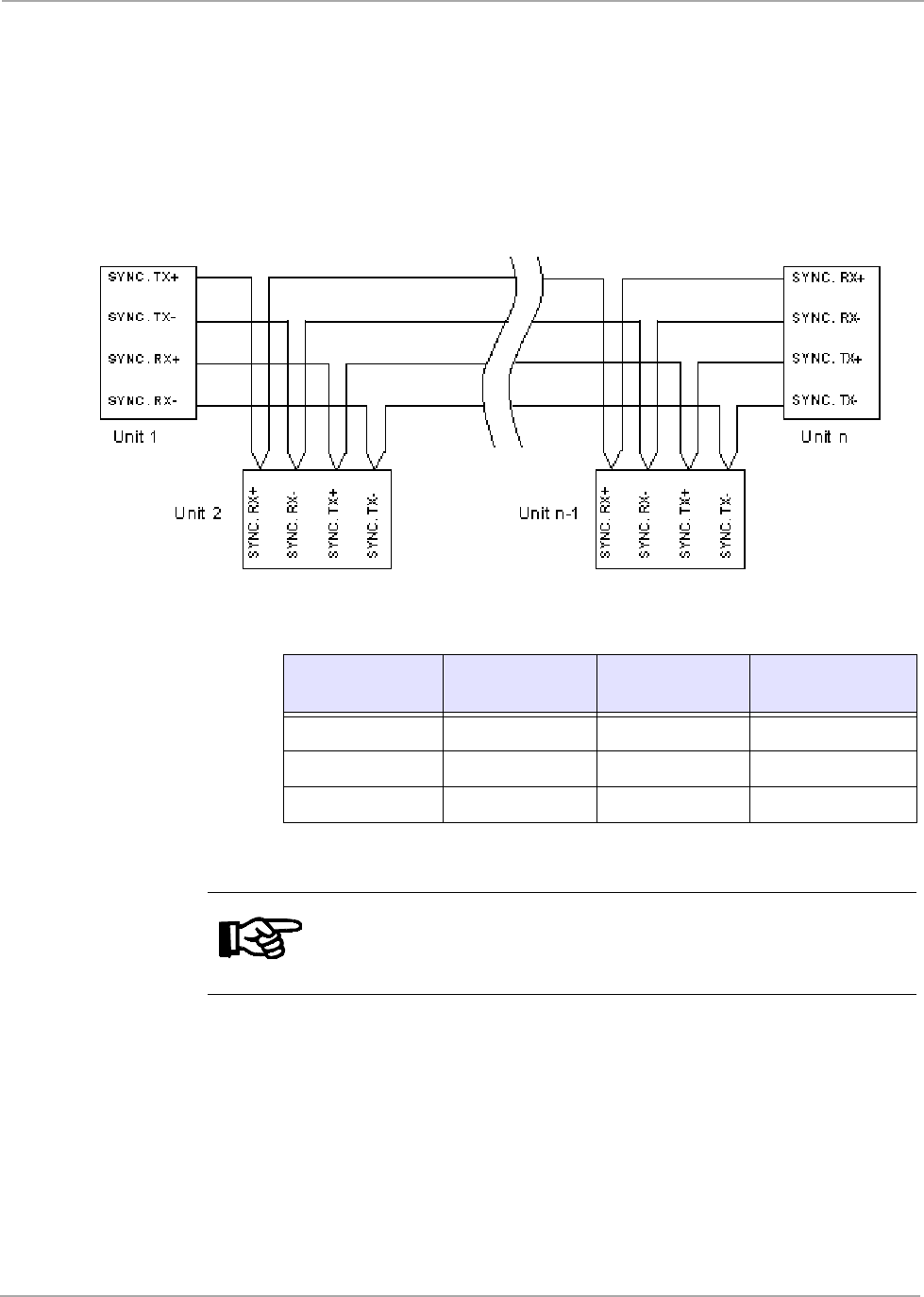
4.5.5 Master/Slave (with acknowledgement)
Figure 12 shows the way that the Readers have to be connected for master/slave
synchronization with acknowledgement. Make sure that you set the software
configuration to Master or Slave (according to Table 34) when you are configuring
the reader.
Table 34 shows the setting of DIP switch switches 1, 2 & 3.
Figure 12: Master/Slave Synchronization Interface Connection
Table 34: Master/Slave Synchronization With Acknowledgement
Line Termination
Dip Switch Unit 1: (Master) Unit 2...Unit n-1:
(Slaves) UNIT n: (Slave)
SW1 ON OFF ON
SW2 ON OFF ON
SW3 ON OFF ON (see Note)
Note:
If the distance between Unit 1 and Unit n is less than approximately
400 m, DIP switch SW3 can be left OFF.
37
April ’00 Chapter 4. Installation
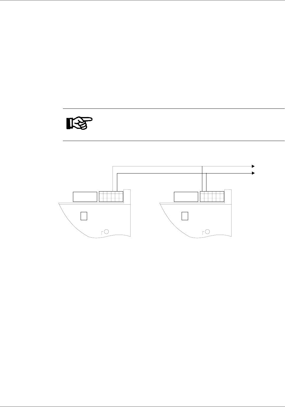
4.5.6 Transmitter Carrier Phase Synchronisation (CPS)
To allow you to overcome the beat effect, the pulse width modulated oscillator signal
is accessible at the CPS connector D. All readers to be driven by one oscillator must
have their CPS connectors connected together as shown in Figure 13.
DIP switch Synchronization-SW4 determines whether the internal oscillator or the
external oscillator signal is used. When the DIP switch Synchronization-SW4 is OFF,
the internal oscillator is used and the reader is referred to as an oscillator MASTER.
When the DIP Switch Synchronization-SW4 is ON, the external oscillator signal is
used and the reader is referred to as an oscillator SLAVE.
Figure 13: Carrier Phase Synchronisation Interface Connection
Master Slave
If you are using carrier phase synchronization you must configure your system to
Master/Slave in order to have one common master.
Note:
Only one oscillator MASTER is allowed per synchronized system.
to other
units

38
S2510 Reader - Reference Guide April ’00
4.6 General Purpose Input/Outputs
The S251B Reader has 8 connections that can be defined as either inputs or outputs
(TTL level). These input/outputs must be configured in groups of 4 as shown in Table
35.
I = Input; O = Output
Table 35: General Purpose Inputs/Outputs
I/O I/O
0 1 2 3 4 5 6 7
I I I I I I I I
I I I I O O O O
O O O O I I I I
O O O O O O O O
39
April ’00 Chapter 4. Installation
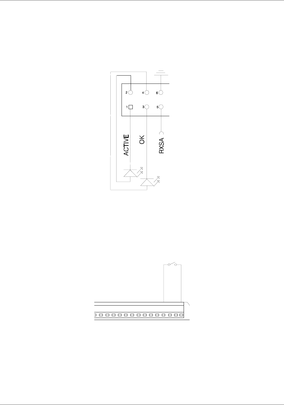
4.7 LED Outputs
The signals used for the indicator LEDs (Read O.K. and Transmitting) are available
at Indicator Outputs connector (H), they can be used to drive external LEDs or buzz-
ers, they must be connected as shown in Figure 14. Ensure that the values given Ta-
ble 18 are not exceeded.
Figure 14: Connecting the LED Outputs
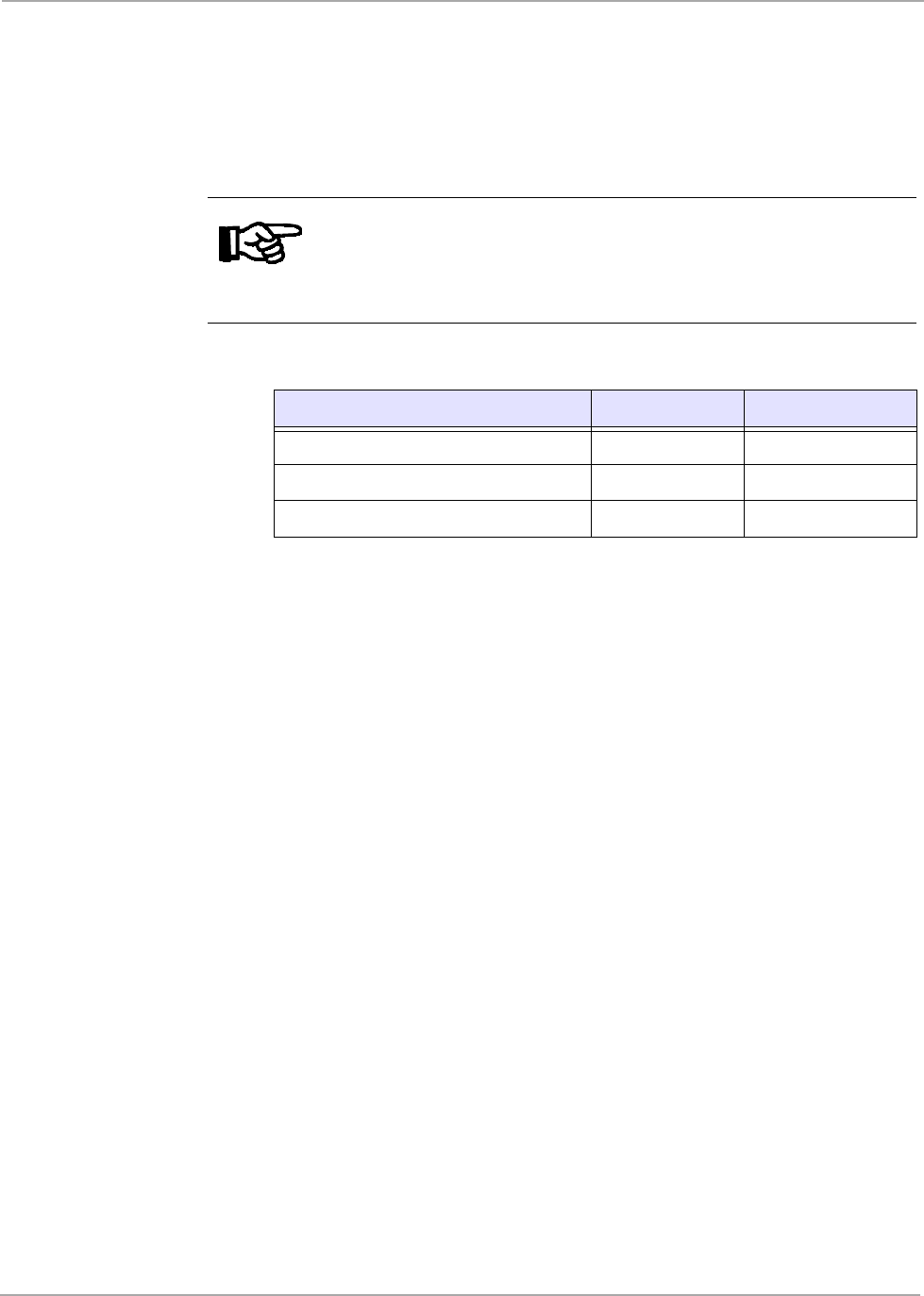
4.8 Reset
The S251B Reader provides a connection for an external reset on pin 12 of the Gen-
eral Purpose Input / Output connector (B). This pin can be used reset the S251B
Reader externally. You can apply an external reset to the reader by connecting a
push-button to the connectors as shown in Figure 15.
Figure 15: RESET Push-button Wiring
GENERAL I/O PORT
RESET-
GND
12
15
40
S2510 Reader - Reference Guide April ’00
4.9 Antenna
The S251B Reader can be used together with the TIRIS antennas RI-ANT-G01E, RI-
ANT-G02E, RI-ANT-G04E and RI-ANT-S02C. If you wish to use it with your own de-
sign antenna that antenna must conform to the specifications given in Table 36.
Table 36: Antenna Specifications
The antenna must be connected to the terminals marked Antenna on the S251B.
4.10 RF Power Output Adjustment
Use the RF Power Output Adj. potentiometer to adjust the internal oscillator pulse
width and subsequently the antenna output voltage to conform to your local regula-
tions. Turning the potentiometer clockwise causes the field strength to increase.
4.11 EMI / Sync. Level Adjustment
EMI / Sync. Level Adj. potentiometer to adjust the receiver signal strength threshold
for the wireless synchronization. Turning the potentiometer clockwise results in a
maximum sensitivity.
If wireless synchronization is used, it is important that the EMI/Sync level Adj. poten-
tiometer is correctly adjusted. This is one of the final adjustments to the reader and
is done on site in the final location once the antenna has been tuned and ALL THE
OTHER READER ARE SWITCHED OFF.
Turning the potentiometer adjusts the receiver signal level threshold and you must
set the reader’s ‘base level noise’ in its final location, so that any signal larger than
the base level triggers the synchronization algorithm.
Send a single ‘X’ (execute command) to the reader to stop any continuous reading,
and then turn the potentiometer clockwise until the yellow LED is fully lit. Slowly ad-
just the potentiometer back until the LED just goes out. Adjustment is then complete.
Note:
The Stick Antenna (RI-ANT-S02C) must only be used together with a
reader supply voltage up to 12 V. If you use this antenna with a higher
reader supply voltage the antenna becomes too warm which effects
the antenna’s Q.
Parameter Minimum Maximum
Antenna Resonance Voltage - 380 Vpeak
Antenna Inductance 26.0 µH 27.9 µH
Antenna Q-factor 40 350

CHAPTER 5
41
Warnings, Cautions and Notices
Chapter 5: Warnings, Cautions and Notices
This chapter provides the Warnings, Cautions and Notices that are relevant to the
S251B reader.
Topic Page
5.1 FCC/PTT Regulations ................................................................................42
5.2 Important note to Purchasers/Users of the S251B Reader in the U.S.A.42
5.3 WARNING....................................................................................................42

42
S2510 Reader - Reference Guide April ’00
5.1 FCC/PTT Regulations
The TIRIS Reader RF produces emissions at 134.2 kHz. The radiation of the funda-
mental and the harmonics will vary with the type of antenna and other devices or
functions connected to the Reader.
Prior to operating the S251B Reader together with antenna(s) and power supply, the
required FCC, PTT or relevant government agency approvals must be ob-
tained.Sale, lease or operation in some countries may be subject to prior approval by
the government or other organizations.
5.2 Important note to Purchasers/Users of the S251B Reader in the U.S.A.
The TIRIS Reader is considered by the Federal Communications Commission (FCC)
to be a "subassembly". As such, no prior approval is required to import, sell or other-
wise market the Reader in the United States. In order to form a functioning radio fre-
quency (RF) device, the Reader must be connected to a suitable antenna and power
supply. A radio frequency device may not be operated unless authorized by the FCC
nor may a radio frequency device be marketed (i.e. sold, leased, imported, or adver-
tised for sale or lease) without the prior grant of an FCC equipment authorization.
FCC authorization to operate an RF device may take one of two forms: first, the FCC
may grant the user an experimental license; second, the FCC may issue an equip-
ment authorization permitting use of the RF device on an unlicensed basis. TI can
assist the user in obtaining an experimental license that will cover a specific installa-
tion of the S251B Reader in a specific site or sites. Experimental authorizations are
appropriate to cover operations during the development of an RF device. A grant of
equipment authorization (known as "certification") must be obtained from the FCC
before RF devices are marketed or operated on a non development basis.
DEVICES CONSTRUCTED FOR EVALUATION INCORPORATING THIS Reader
SHOULD BE OPERATED ONLY UNDER AN EXPERIMENTAL LICENSE ISSUED
BY THE FCC AND MAY NOT BE MARKETED. BEFORE ANY DEVICE CONTAIN-
ING THIS Reader IS MARKETED, AN EQUIPMENT AUTHORIZATION FOR THE
DEVICE MUST BE OBTAINED FROM THE FCC.
Prospective marketers of devices containing this Reader are responsible for obtain-
ing the necessary equipment authorization. Upon request TI can provide assistance
in obtaining FCC approval to market devices incorporating this Reader.
5.3 WARNING
Care must be taken when handling the S251B. High voltage across the antenna ter-
minals could be harmful to your health. If the antenna insulation is damaged the an-
tenna should not be connected to the Reader.