Thales Communications EVR718 EVR 716 VHF data radio User Manual OPERATION AND INSTALLATION MANUAL
THALES Communications EVR 716 VHF data radio OPERATION AND INSTALLATION MANUAL
Contents
- 1. OPERATION AND INSTALLATION MANUAL
- 2. ExhibitC - Manual
OPERATION AND INSTALLATION MANUAL
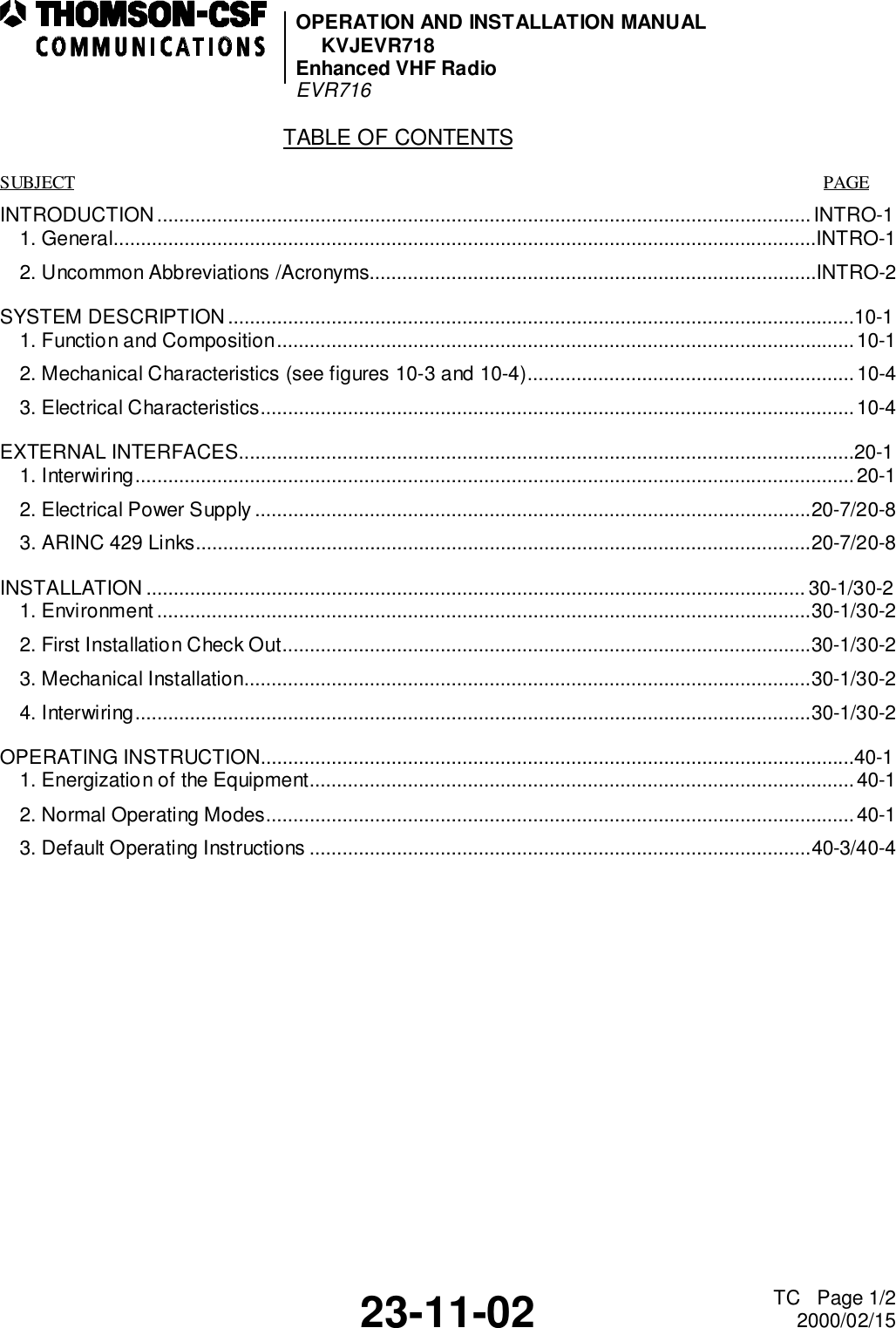
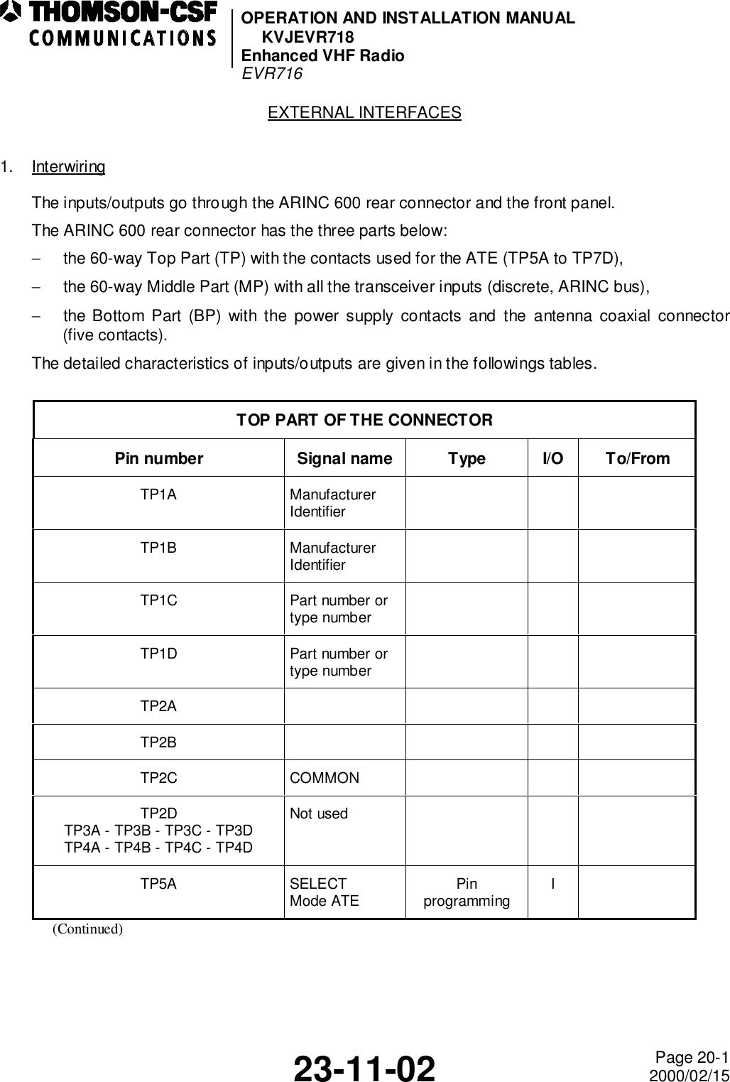
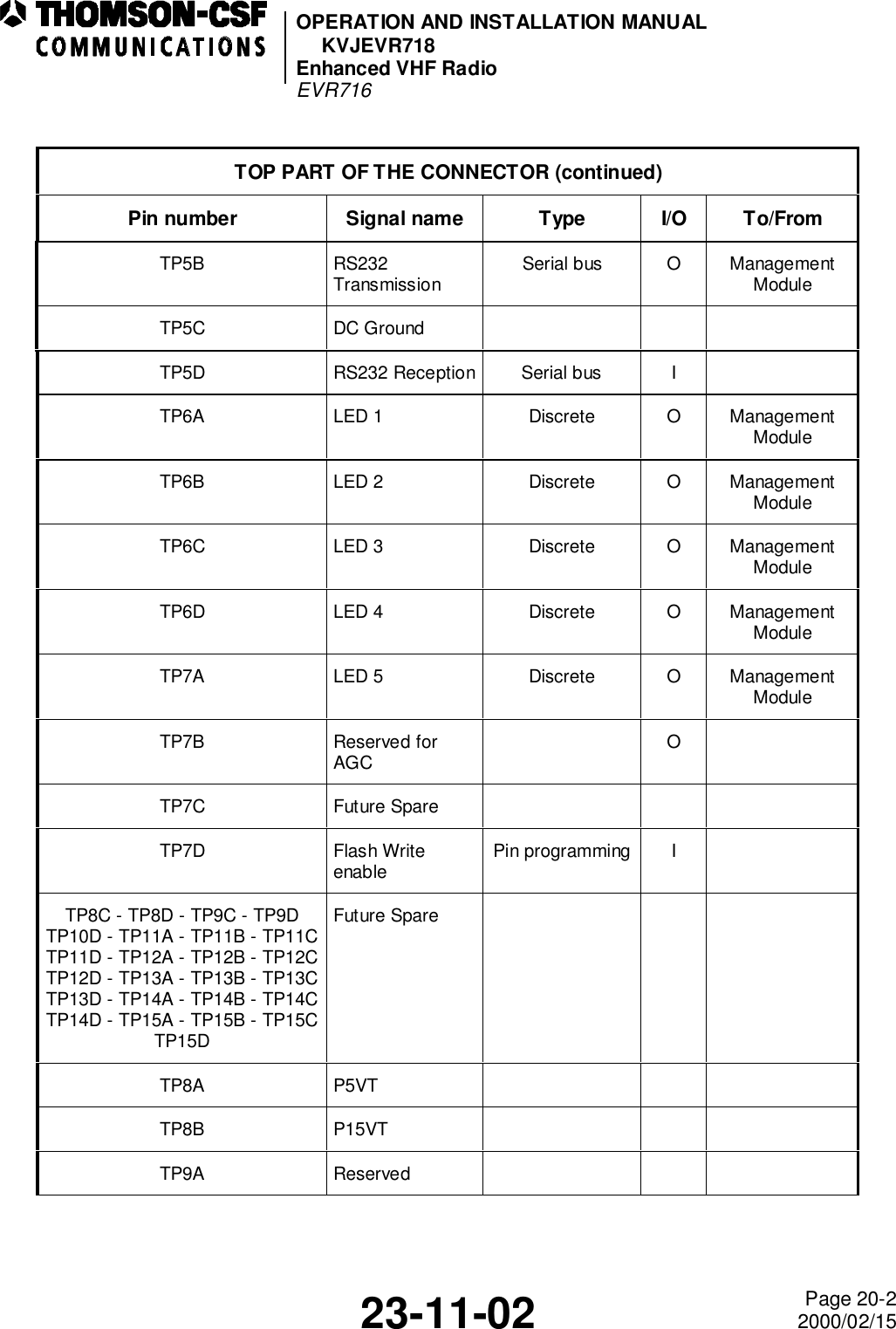
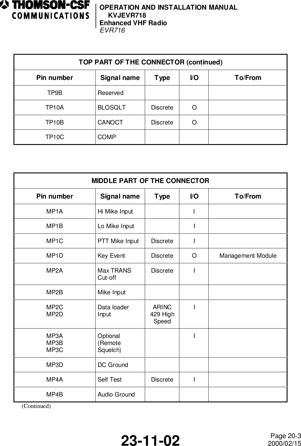
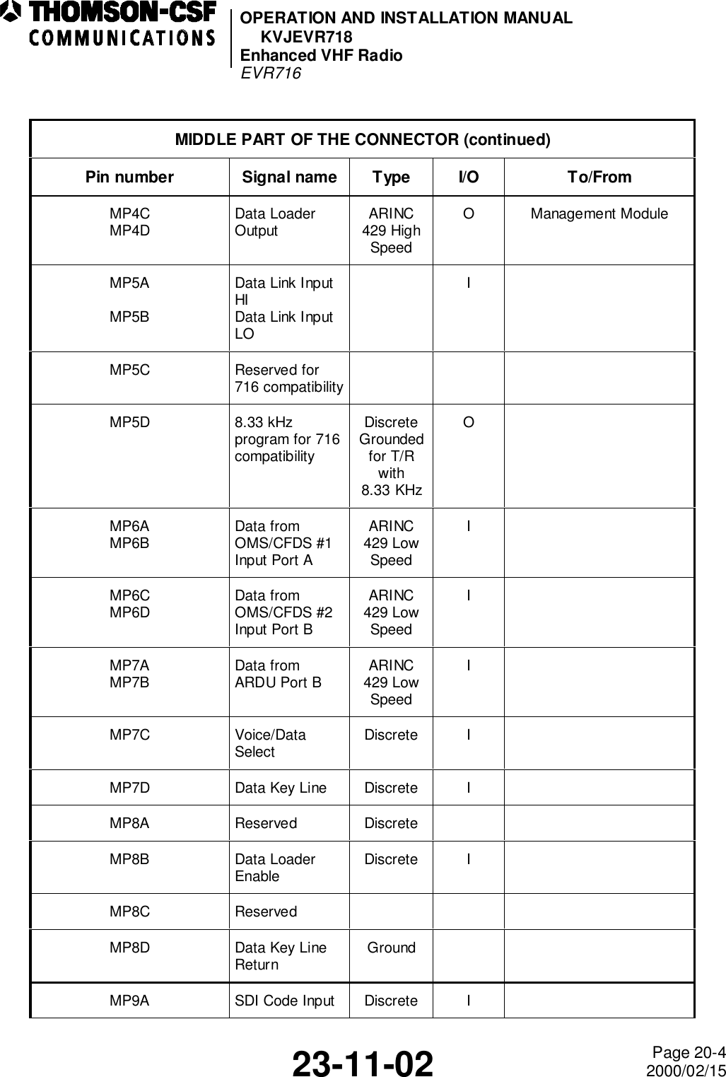
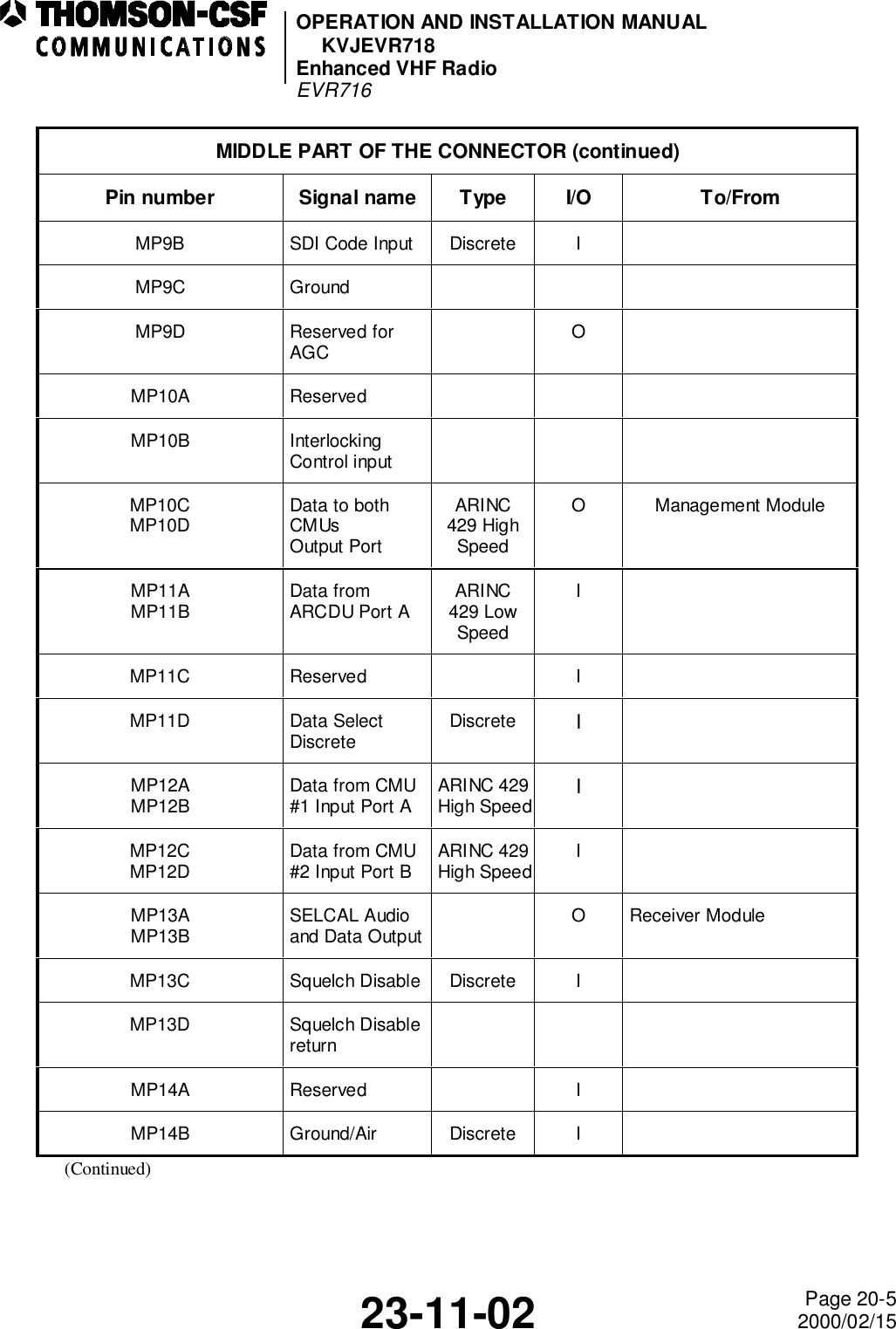
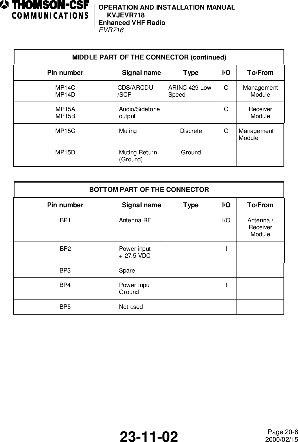
![OPERATION AND INSTALLATION MANUALKVJEVR718Enhanced VHF RadioEVR71623-11-02 Introduction Page 12000/02/15INTRODUCTION1. GeneralThis Operation and Installation Manual includes information related to the operation andinstallation of the THOMSON-CSF COMMUNICATIONS EVR716 Enhanced VHF RadioCommunications Transceiver.The Operation and Installation instructions are presented in the following sections:Introduction.10 - System Description.20 - External Interfaces.30 - Installation.40 - Operating Instruction.CAUTION: THE EQUIPMENT IN THIS MANUAL IS SUBJECT TO CHANGE. BEFOREATTEMPTING ANY OPERATION ON THE EQUIPMENT COVERED IN THISMANUAL, VERIFY THAT YOU HAVE COMPLETE AND UP-TO-DATEPUBLICATIONS BY REFERRING TO THE APPLICABLE PUBLICATIONS,SERVICE BULLETIN, SERVICE BULLETIN LIST, SERVICE INFORMATIONLETTER INDEXES.Refer to the Table of Contents for the page location of applicable sections.An asterisk flagnote *[ ] in place of the page number indicates that no special instructions areprovided since the function can be performed using standard industry practices.A list of uncommon/acronyms abbreviations used in this manual is described in paragraph 2 ofthe INTRODUCTION SECTION. This manual will be revised as necessary to reflect currentinformation.We welcome your comments concerning this manual. Although every effort has been made tokeep it free of errors, some may occurs. When reporting a specific problem, please describe itbriefly and include the manual part number, the paragraph or figure number, and the pagenumber.Send your comments to:SEXTANTAérodrome de VillacoublayB.P.5978 141 VELIZY-VILLACOUBLAY CEDEX](https://usermanual.wiki/Thales-Communications/EVR718.OPERATION-AND-INSTALLATION-MANUAL/User-Guide-99245-Page-11.png)