Thales Communications EVR718 EVR 716 VHF data radio User Manual OPERATION AND INSTALLATION MANUAL
THALES Communications EVR 716 VHF data radio OPERATION AND INSTALLATION MANUAL
Contents
- 1. OPERATION AND INSTALLATION MANUAL
- 2. ExhibitC - Manual
OPERATION AND INSTALLATION MANUAL

OPERATION AND INSTALLATION MANUAL
KVJEVR718
Enhanced VHF Radio
EVR716

OPERATION AND INSTALLATION MANUAL
KVJEVR718
Enhanced VHF Radio
EVR716 LISTE DES RENVOIS
ATA
23-11-02
Fabricant
P/N
Date d'édition originale: 2000/02/15
Date d'édition révision 2000/02/15

KVJEVR718
F0057
FIRST ISSUE: 2000/02/15
Ref/Doc : 36710392-AA
REVISION No.: 23-11-02 TP Page 1/2
2000/02/15
OPERATION AND INSTALLATION MANUAL
Enhanced VHF Radio
VHF Communications Transceiver
PN : EVR716-11-0300A
EVR716-11-0350A

OPERATION AND INSTALLATION MANUAL
KVJEVR718
Enhanced VHF Radio
EVR716
23-11-02 SILL Page 1/2
2000/02/15
SERVICE INFORMATION LETTER LIST
SERVICE
INFORMATION
LETTER
No
INCLUDED
IN
REVISION
DATE
OF
INCORPORATION TITLE
1 - - Not applicable for P/Ns :
EVR716-11-0300A and EVR716-
11-0350A.
2 First Issue 2000/02/15 To upgrade the current
Transmitter (TX), Receiver (RX),
and HIRF boards to industrial
level a re-layout of the printed
circuit.

OPERATION AND INSTALLATION MANUAL
KVJEVR718
Enhanced VHF Radio
EVR716
23-11-02 LEP Page 1/2
2000/02/15
LIST OF EFFECTIVE PAGES
SUBJECT PAGE DATE SUBJECT PAGE DATE
Title Page 1 2000/02/15 System 10-1 2000/02/15
2 Blank Description 10-2 2000/02/15
10-3 2000/02/15
Record of 1 2000/02/15 10-4 2000/02/15
Revisions 2 Blank 10-5 2000/02/15
10-6 2000/02/15
Record of 1 2000/02/15
Temporary 2 Blank External 20-1 2000/02/15
Revisions Interfaces 20-2 2000/02/15
20-3 2000/02/15
Service 1 2000/02/15 20-4 2000/02/15
Bulletin List 2 Blank 20-5 2000/02/15
20-6 2000/02/15
Service 1 2000/02/15 20-7 2000/02/15
Information 2 Blank 20-8 Blank
Letter List Installation 30-1 2000/02/15
List of 1 2000/02/15 30-2 Blank
Effective 2 Blank
Pages Operating 40-1 2000/02/15
Instructions 40-2 2000/02/15
Table of 1 2000/02/15 40-3 2000/02/15
Contents 2 Blank 40-4 Blank
List of 1 2000/02/15
Illustrations 2 Blank
Introduction 1 2000/02/15
2 2000/02/15
3 2000/02/15
4Blank
R : Revised (to be replaced)
D : Deleted (to be removed)
N : New (to be incorporated)
OPERATION AND INSTALLATION MANUAL
KVJEVR718
Enhanced VHF Radio
EVR716
23-11-02 RR Page 1/2
2000/02/15
REV. ISSUE INSERTED
No. DATE DATE BY
REV. ISSUE INSERTED
No. DATE DATE BY
RECORD OF REVISIONS

OPERATION AND INSTALLATION MANUAL
KVJEVR718
Enhanced VHF Radio
EVR716
23-11-02 RTR Page 1/2
2000/02/15
RECORD OF TEMPORARY REVISIONS
TEMPORARY
REV Nr PAGE NUMBER ISSUE DATE BY DATE
REMOVED BY

OPERATION AND INSTALLATION MANUAL
KVJEVR718
Enhanced VHF Radio
EVR716
23-11-02 SBL Page 1/2
2000/02/15
SERVICE BULLETIN LIST
SERVICE
BULLETIN
NUMBER
R
E
V
INCLUDED
IN
REVISION
DATE
OF
INCORPORATION
TITLE

OPERATION AND INSTALLATION MANUAL
KVJEVR718
Enhanced VHF Radio
EVR716
23-11-02 TC Page 1/2
2000/02/15
TABLE OF CONTENTS
SUBJECT PAGE
INTRODUCTION........................................................................................................................INTRO-1
1. General.................................................................................................................................INTRO-1
2. Uncommon Abbreviations /Acronyms..................................................................................INTRO-2
SYSTEM DESCRIPTION...................................................................................................................10-1
1. Function and Composition..........................................................................................................10-1
2. Mechanical Characteristics (see figures 10-3 and 10-4)............................................................10-4
3. Electrical Characteristics.............................................................................................................10-4
EXTERNAL INTERFACES.................................................................................................................20-1
1. Interwiring....................................................................................................................................20-1
2. Electrical Power Supply ......................................................................................................20-7/20-8
3. ARINC 429 Links.................................................................................................................20-7/20-8
INSTALLATION ......................................................................................................................... 30-1/30-2
1. Environment ........................................................................................................................30-1/30-2
2. First Installation Check Out.................................................................................................30-1/30-2
3. Mechanical Installation........................................................................................................30-1/30-2
4. Interwiring............................................................................................................................30-1/30-2
OPERATING INSTRUCTION.............................................................................................................40-1
1. Energization of the Equipment....................................................................................................40-1
2. Normal Operating Modes............................................................................................................40-1
3. Default Operating Instructions ............................................................................................40-3/40-4

OPERATION AND INSTALLATION MANUAL
KVJEVR718
Enhanced VHF Radio
EVR716
23-11-02 LI Page 1/2
2000/02/15
LIST OF ILLUSTRATIONS
FIGURE PAGE
10-1 - GENERAL VIEW........................................................................................................10-2
10-2 - INTERFACE BLOCK DIAGRAM ...............................................................................10-2
10-3 - MECHANICAL CHARACTERISTICS........................................................................10-5
10-4 - MECHANICAL CHARACTERISTICS........................................................................10-6

OPERATION AND INSTALLATION MANUAL
KVJEVR718
Enhanced VHF Radio
EVR716
23-11-02 Introduction Page 1
2000/02/15
INTRODUCTION
1. General
This Operation and Installation Manual includes information related to the operation and
installation of the THOMSON-CSF COMMUNICATIONS EVR716 Enhanced VHF Radio
Communications Transceiver.
The Operation and Installation instructions are presented in the following sections:
Introduction.
10 - System Description.
20 - External Interfaces.
30 - Installation.
40 - Operating Instruction.
CAUTION: THE EQUIPMENT IN THIS MANUAL IS SUBJECT TO CHANGE. BEFORE
ATTEMPTING ANY OPERATION ON THE EQUIPMENT COVERED IN THIS
MANUAL, VERIFY THAT YOU HAVE COMPLETE AND UP-TO-DATE
PUBLICATIONS BY REFERRING TO THE APPLICABLE PUBLICATIONS,
SERVICE BULLETIN, SERVICE BULLETIN LIST, SERVICE INFORMATION
LETTER INDEXES.
Refer to the Table of Contents for the page location of applicable sections.
An asterisk flagnote *[ ] in place of the page number indicates that no special instructions are
provided since the function can be performed using standard industry practices.
A list of uncommon/acronyms abbreviations used in this manual is described in paragraph 2 of
the INTRODUCTION SECTION. This manual will be revised as necessary to reflect current
information.
We welcome your comments concerning this manual. Although every effort has been made to
keep it free of errors, some may occurs. When reporting a specific problem, please describe it
briefly and include the manual part number, the paragraph or figure number, and the page
number.
Send your comments to:
SEXTANT
Aérodrome de Villacoublay
B.P.59
78 141 VELIZY-VILLACOUBLAY CEDEX

OPERATION AND INSTALLATION MANUAL
KVJEVR718
Enhanced VHF Radio
EVR716
23-11-02 Introduction Page 2
2000/02/15
2. Uncommon Abbreviations /Acronyms
ABBREVIATIONS/
ACRONYMS IDENTIFICATION
ACARS Aircraft Communication Addressing and Reporting System
AMU Audio Management Unit
ATC Air Traffic Control
BIT Built In Test
CFDS Centralized Fault Display System
CMU Communications Management Unit
CSMA Carrier Sense Multiple Access
DFS Data Frequency System
FM Frequency Modulation
Hz Hertz
LED Light Emitting Diode
LF Low Frequency
LO Local Oscillator
LRU Line Replaceable Unit
MHz Megahertz
MU Management Unit
OMS On-board Maintenance System
P/N Part Number
Rx Receiver
SDI Source Destination Identifier
SELCAL SELective CALling
SRU Shop Replaceable Unit
T/R Transmitter/Receiver
Tx Transmitter
(Continued)

OPERATION AND INSTALLATION MANUAL
KVJEVR718
Enhanced VHF Radio
EVR716
23-11-02 Introduction Page 3/4
2000/02/15
ABBREVIATIONS/
ACRONYMS IDENTIFICATION
UHF Ultra High Frequency
VAC Voltage Alternative Current
VDC Voltage Direct Current
VHF Very High Frequency
VHFCP VHF Control Panel
EVR Enhanced VHF Radio

OPERATION AND INSTALLATION MANUAL
KVJEVR718
Enhanced VHF Radio
EVR716
23-11-02 Page 10-1
2000/02/15
SYSTEM DESCRIPTION
1. Function and Composition
The Radio communication airborne system (see figure 10-1), known as the EVR716, is a VHF
transceiver operating in the aeronautical band (118 MHz to 137 MHz), used by Air Transport
Aircraft as a primary equipment for communications with the ground ATC infrastructure (in
continental areas) or for communications between aircrafts (relay, emergency).
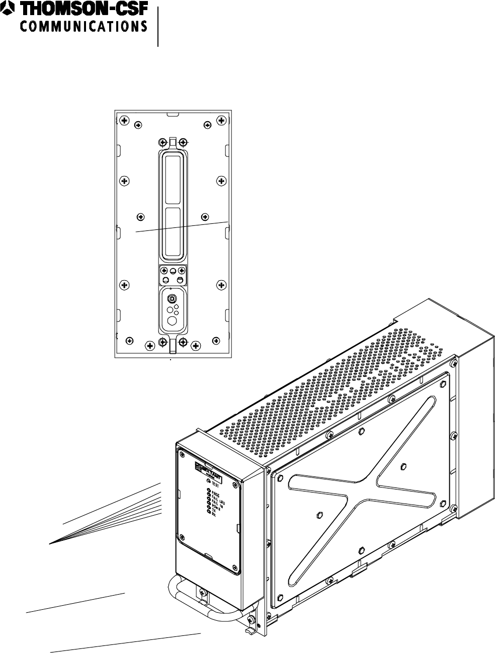
The EVR716 transceiver includes:
− On the rear panel:
• an ARINC 600 connector, size 1.
− On the front panel:
• two attaching lugs,
• a handle,
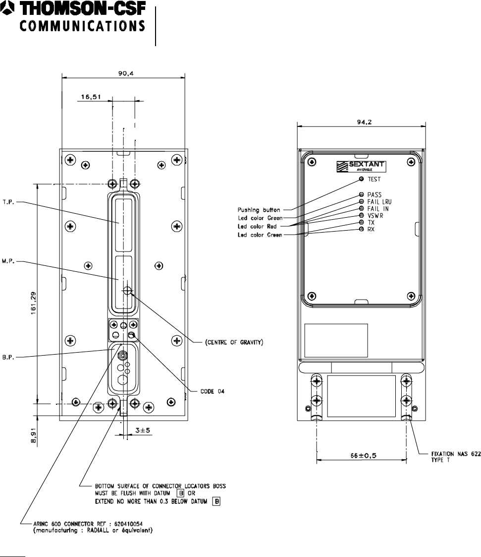
• a test pushbutton,
• six display LEDs.
The EVR716 transceiver is identified by labels stuck on its front panel.
The first label mentions:
− the equipment name,
− the TSO,
− the Quality Control,
− the serial number (S/N),
− the factory clearance date.
The second label mentions the service bulletin numbers applied.
The third label mentions the commercial reference.
The fourth label mentions the QAC.
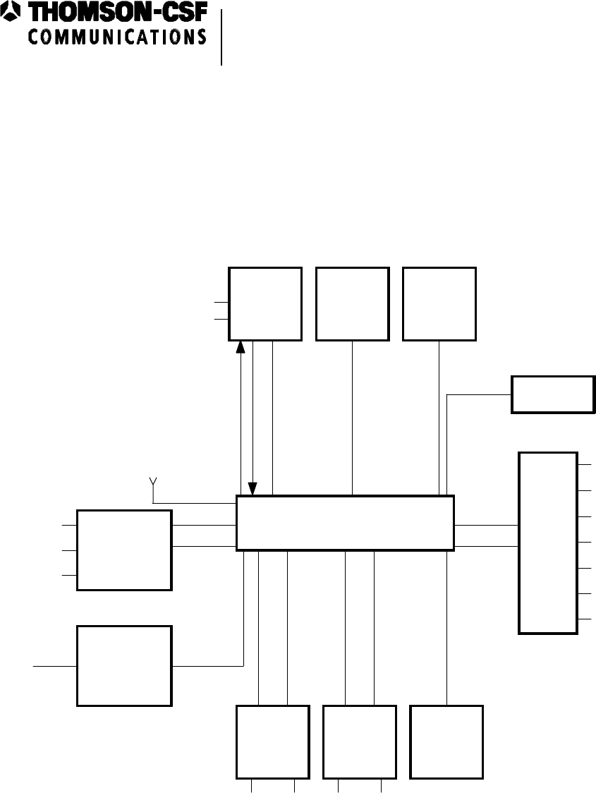
Aboard the aircraft (see figure 10-2), the EVR716 transceiver operates with the items of
equipment below:
− a Data Frequency System (DFS) which can be an RCU (Radio Control Unit or control unit)
or an RMP (Radio Management Panel) to agree with the aircraft configuration,
OPERATION AND INSTALLATION MANUAL
KVJEVR718
Enhanced VHF Radio
EVR716
23-11-02 Page 10-2
2000/02/15
A0Z-MAA1
General view
Figure 10-1
Interface block diagram
Figure 10-2
Handle
Attaching lug
Test pushbutton
Display LEDs
ARINC 600 connector
Rear panel
OPERATION AND INSTALLATION MANUAL
KVJEVR718
Enhanced VHF Radio
EVR716
23-11-02 Page 10-3
2000/02/15
EVR 716
A
udio
A
ntenna RF in
Discret
Audio
Selector
Panel
(
ASP
)
Fre
q
in
Mike in PTT
A
udio out
CMU/MU
Communications
Mana
g
ement
Unit
CMU
Data
In/Out
A
RINC
429 HS
Aiborne or
Portable
Data Loader
Discret
A
RINC
429 HS
Data Loader
Enable Data
In/Out
ACARS
Discret
A
udio
Data
Ke
y
line Data Link
,
Data In
p
ut
SELCAL
or Data
Out
p
ut
A
udio
Discret
A
nalo
g
Others
SDI Code
Ground/Air
Self Test
Max Trans Cut off
Voice/Data Select
Reserved for AGC
Ke
y
Event
Discrets
A
RINC
429 LS
A
udio
V
HF
Control
Panel
(
VHFCP
)
OMS/CFDS
Automatic
Test
E
q
ui
p
ment
(
ATE
)
A
RINC
429 LS Serial
Line
POWER SUPPLY
+27.5 VDC
Ground
Mike in
S
q
uelch Disable
A
0Z-SA-A
2x

OPERATION AND INSTALLATION MANUAL
KVJEVR718
Enhanced VHF Radio
EVR716
23-11-02 Page 10-4
2000/02/15
− an ACARS MU (Management Unit, ARINC 724 or 724A) or a CMU (Communications
Management Unit, ARINC 758),
− an Audio Management Unit (AMU), audio control panel (microphone, loudspeakers),
− a maintenance computer : OMS (ARINC 624) or CFDS (ARINC 604),
− a VHF antenna.
2. Mechanical Characteristics (see figures 10-3 and 10-4)
DESIGNATION DIMENSIONS (mm) WEIGHT (kg)
T/R Unit EVR716 3 MCU to ARINC 600
ie 200 x 94 x 387.5 4.450 ± 0.050
3. Electrical Characteristics
− Frequency range : 117.975 MHz to 137 MHz
− Transmitted power : 16 W
− Power Supply : 28 VDC
− Modes of operation:
• Mode OA : Analogue voice transmission, 25 kHz channel spacing
• Mode OB : Analogue voice transmission, 8.33 kHz channel spacing
• Mode 1A : Data, 25 kHz channel spacing,
AM-MSK modulation (2.4 kb/s),
external modem, CSMA access,
ACARS protocol.
OPERATION AND INSTALLATION MANUAL
KVJEVR718
Enhanced VHF Radio
EVR716
23-11-02 Page 10-5
2000/02/15
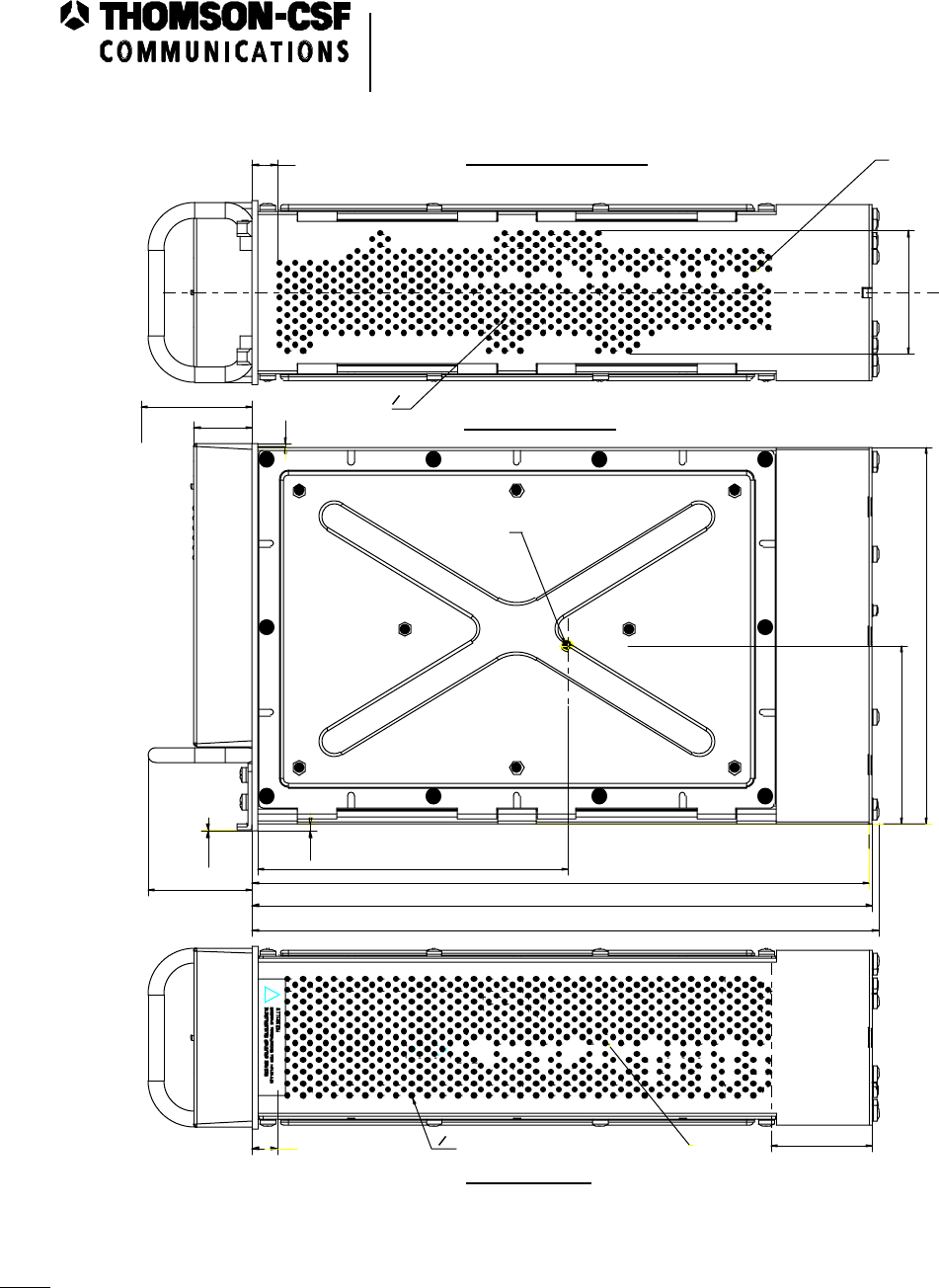
NOTE: All dimensions are in mm.
A0Z-MAA2
Mechanical characteristics
Figure 10-3
OPERATION AND INSTALLATION MANUAL
KVJEVR718
Enhanced VHF Radio
EVR716
23-11-02 Page 10-6
2000/02/15
57,3
323
52
92 5
3,6
0,5
2
53,5
63,5
O 3
194
0
-0,1
319,5
30
13
13
CENTRE OF GRAVITY
OUTLET AREA
INTLET AREA
+
-
318 5
+
-
BOTTOM VIEW
RIGHT VIEW
TOP VIEW
NOTE : All dimensions are in mm.
160 5
+
-
O 3
A0Z-MAA2
NOTE: All dimensions are in mm. Mechanical characteristics
Figure 10-4

OPERATION AND INSTALLATION MANUAL
KVJEVR718
Enhanced VHF Radio
EVR716
23-11-02 Page 20-1
2000/02/15
EXTERNAL INTERFACES
1. Interwiring
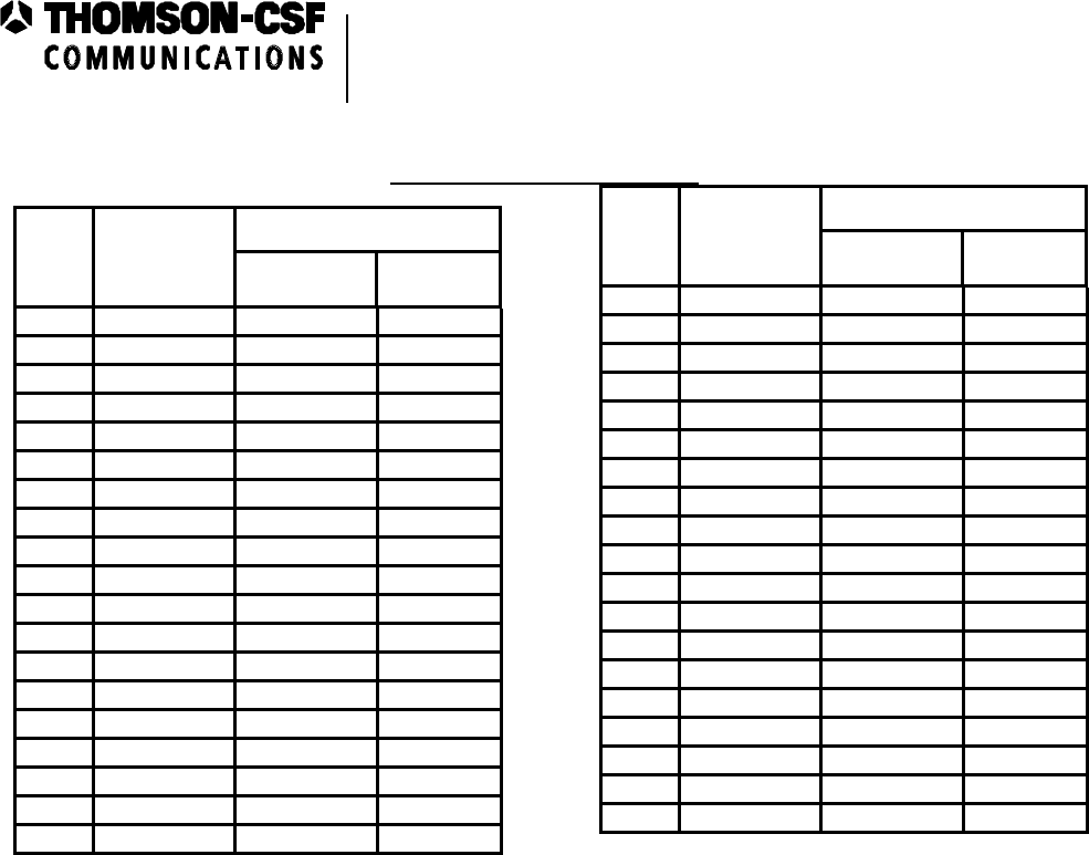
The inputs/outputs go through the ARINC 600 rear connector and the front panel.
The ARINC 600 rear connector has the three parts below:
− the 60-way Top Part (TP) with the contacts used for the ATE (TP5A to TP7D),
− the 60-way Middle Part (MP) with all the transceiver inputs (discrete, ARINC bus),
− the Bottom Part (BP) with the power supply contacts and the antenna coaxial connector
(five contacts).
The detailed characteristics of inputs/outputs are given in the followings tables.
TOP PART OF THE CONNECTOR
Pin number
Signal name
Type
I/O
To/From
TP1A Manufacturer
Identifier
TP1B Manufacturer
Identifier
TP1C Part number or
type number
TP1D Part number or
type number
TP2A
TP2B
TP2C COMMON
TP2D
TP3A - TP3B - TP3C - TP3D
TP4A - TP4B - TP4C - TP4D
Not used
TP5A SELECT
Mode ATE Pin
programming I
(Continued)

OPERATION AND INSTALLATION MANUAL
KVJEVR718
Enhanced VHF Radio
EVR716
23-11-02 Page 20-2
2000/02/15
TOP PART OF THE CONNECTOR (continued)
Pin number
Signal name
Type
I/O
To/From
TP5B RS232
Transmission Serial bus O Management
Module
TP5C DC Ground
TP5D RS232 Reception Serial bus I
TP6A LED 1 Discrete O Management
Module
TP6B LED 2 Discrete O Management
Module
TP6C LED 3 Discrete O Management
Module
TP6D LED 4 Discrete O Management
Module
TP7A LED 5 Discrete O Management
Module
TP7B Reserved for
AGC O
TP7C Future Spare
TP7D Flash Write
enable Pin programming I
TP8C - TP8D - TP9C - TP9D
TP10D - TP11A - TP11B - TP11C
TP11D - TP12A - TP12B - TP12C
TP12D - TP13A - TP13B - TP13C
TP13D - TP14A - TP14B - TP14C
TP14D - TP15A - TP15B - TP15C
TP15D
Future Spare
TP8A P5VT
TP8B P15VT
TP9A Reserved

OPERATION AND INSTALLATION MANUAL
KVJEVR718
Enhanced VHF Radio
EVR716
23-11-02 Page 20-3
2000/02/15
TOP PART OF THE CONNECTOR (continued)
Pin number
Signal name
Type
I/O
To/From
TP9B Reserved
TP10A BLOSQLT Discrete O
TP10B CANOCT Discrete O
TP10C COMP
MIDDLE PART OF THE CONNECTOR
Pin number
Signal name
Type
I/O
To/From
MP1A Hi Mike Input I
MP1B Lo Mike Input I
MP1C PTT Mike Input Discrete I
MP1D Key Event Discrete O Management Module
MP2A Max TRANS
Cut-off Discrete I
MP2B Mike Input
MP2C
MP2D Data loader
Input ARINC
429 High
Speed
I
MP3A
MP3B
MP3C
Optional
(Remote
Squelch)
I
MP3D DC Ground
MP4A Self Test Discrete I
MP4B Audio Ground
(Continued)

OPERATION AND INSTALLATION MANUAL
KVJEVR718
Enhanced VHF Radio
EVR716
23-11-02 Page 20-4
2000/02/15
MIDDLE PART OF THE CONNECTOR (continued)
Pin number
Signal name
Type
I/O
To/From
MP4C
MP4D Data Loader
Output ARINC
429 High
Speed
O Management Module
MP5A
MP5B
Data Link Input
HI
Data Link Input
LO
I
MP5C Reserved for
716 compatibility
MP5D 8.33 kHz
program for 716
compatibility
Discrete
Grounded
for T/R
with
8.33 KHz
O
MP6A
MP6B Data from
OMS/CFDS #1
Input Port A
ARINC
429 Low
Speed
I
MP6C
MP6D Data from
OMS/CFDS #2
Input Port B
ARINC
429 Low
Speed
I
MP7A
MP7B Data from
ARDU Port B ARINC
429 Low
Speed
I
MP7C Voice/Data
Select Discrete I
MP7D Data Key Line Discrete I
MP8A Reserved Discrete
MP8B Data Loader
Enable Discrete I
MP8C Reserved
MP8D Data Key Line
Return Ground
MP9A SDI Code Input Discrete I

OPERATION AND INSTALLATION MANUAL
KVJEVR718
Enhanced VHF Radio
EVR716
23-11-02 Page 20-5
2000/02/15
MIDDLE PART OF THE CONNECTOR (continued)
Pin number
Signal name
Type
I/O
To/From
MP9B SDI Code Input Discrete I
MP9C Ground
MP9D Reserved for
AGC O
MP10A Reserved
MP10B Interlocking
Control input
MP10C
MP10D Data to both
CMUs
Output Port
ARINC
429 High
Speed
O Management Module
MP11A
MP11B Data from
ARCDU Port A ARINC
429 Low
Speed
I
MP11C Reserved I
MP11D Data Select
Discrete Discrete
I
MP12A
MP12B Data from CMU
#1 Input Port A ARINC 429
High Speed
I
MP12C
MP12D Data from CMU
#2 Input Port B ARINC 429
High Speed I
MP13A
MP13B SELCAL Audio
and Data Output O Receiver Module
MP13C Squelch Disable Discrete I
MP13D Squelch Disable
return
MP14A Reserved I
MP14B Ground/Air Discrete I
(Continued)

OPERATION AND INSTALLATION MANUAL
KVJEVR718
Enhanced VHF Radio
EVR716
23-11-02 Page 20-6
2000/02/15
MIDDLE PART OF THE CONNECTOR (continued)
Pin number
Signal name
Type
I/O
To/From
MP14C
MP14D CDS/ARCDU
/SCP ARINC 429 Low
Speed O Management
Module
MP15A
MP15B Audio/Sidetone
output O Receiver
Module
MP15C Muting Discrete O Management
Module
MP15D Muting Return
(Ground) Ground
BOTTOM PART OF THE CONNECTOR
Pin number
Signal name
Type
I/O
To/From
BP1 Antenna RF I/O Antenna /
Receiver
Module
BP2 Power input
+ 27.5 VDC I
BP3 Spare
BP4 Power Input
Ground I
BP5 Not used

OPERATION AND INSTALLATION MANUAL
KVJEVR718
Enhanced VHF Radio
EVR716
23-11-02 Page 20-7/20-8
2000/02/15
The links with the aircraft environment are distributed as follows:
− Antenna Input/Output via a coaxial insert located in the lower part of the rear connector.
− Power supply inputs.
− Discrete Inputs/Outputs.
− Serial ARINC 429 link (four low speed inputs and one output, three high speed inputs and
two outputs).
2. Electrical Power Supply
The EVR716 transceiver is directly connected to the aircraft 28 VDC primary power supply via
the aircraft switchboard.
3. ARINC 429 Links
The EVR716 transceiver has four links by ARINC 429 bus:
− a link with the frequency selection equipment, two low speed inputs (MP7A/B, MP11A/B),
− a link with ARINC 615-1 software downloading system, one high speed input and one high
speed output (MP2C/D, MP4C/D),
− a link with the OMS/CFDS on-board maintenance systems, two low speed inputs and one
low speed output (MP6A/B, MP6C/D, MP14C/D),
− a link with the (C)MUs, two high speed inputs and one high speed output (MP12A/B,
MP12C/D, MP10C/D).

OPERATION AND INSTALLATION MANUAL
KVJEVR718
Enhanced VHF Radio
EVR716
23-11-02 Page 30-1/30-2
2000/02/15
INSTALLATION
1. Environment
The EVR716 transceiver is provided for the following environmental conditions:
− Operating temperature : - 40°C to + 70°C (- 40°F to + 158°F)
− Storage temperature : - 55°C to + 85°C (- 67°F to + 185°F)
− Ventilation : The EVR716 transceiver has an inlet air area on its bottom
face and an outlet air area on its top face (see figure
10-4).
2. First Installation Check Out
Prior to install the EVR716 transceiver, check all interwiring for continuity and isolation.
Install and connect the EVR716 transceiver (see paragraph 3).
Energize the equipment and check that the green LED (PASS) lights on.
3. Mechanical Installation
The EVR716 transceiver is provided to be mounted in a rack in the aircraft. The EVR716
transceiver is equipped with two ARINC 600 attaching lugs (see figure 10-1). The mechanical
installation complies with requirements as defined by the ARINC 600 specifications.
The figures 10-2 and 10-3 show the mechanical characteristics of the EVR716 transceiver.
After installation, energize the equipment and check that the green LED (PASS) lights on.
4. Interwiring
The interwiring complies with requirements as defined by the ARINC 600 specifications.

OPERATION AND INSTALLATION MANUAL
KVJEVR718
Enhanced VHF Radio
EVR716
23-11-02 Page 40-1
2000/02/15
OPERATING INSTRUCTION
1. Energization of the Equipment
The EVR716 transceiver is not provided with an "ON-OFF" switch. The EVR716 transceiver
starts operating as soon as 28 VDC is applied to the connector of the EVR716 unit.
2. Normal Operating Modes
The EVR716 transceiver is not provided with operating buttons. It operate via the aircraft
controls.
A. Operational State
This is the EVR716 transceiver normal operating. A BITE device initializing the cyclic tests
allows checking operation of the EVR716 transceiver and indicating failures.
B. Modes
(1)Operating Modes
The operating modes are the following:
(a) Mode 0A
− 25 kHz analog voice transmission (ED-23B, DO-186A : receiver class C,
transmitter class 3; ARINC 716).
− RF modulation : Amplitude modulation with double side bands.
− 25 kHz channelling.
− Link with the microphone : normal audio input/output.
(b) Mode 0B
− 8.33 kHz analog voice transmission (ED-23B, DO-186A : receiver class E,
transmitter class 5; ARINC 716).
− RF modulation : Amplitude modulation with double side bands.
− 8.33 kHz channelling.
− Link with the microphone : normal audio input/output.
(c) Mode 1A
− Data transmission with modem outside the transceiver. ACARS protocol
(ARINC 716, ARINC 618).
− RF modulation : Minimum Shift Keying Amplitude Modulation
(MSK-AM).
− Channelling : 25 kHz.
− Rate : 2.4 kb/s.
− Access to the CSMA : non-persistent.
NOTE : This modem function is performed by the (C)MU)
− Link with the (C)MU : twisted pair analog signal.

OPERATION AND INSTALLATION MANUAL
KVJEVR718
Enhanced VHF Radio
EVR716
23-11-02 Page 40-2
2000/02/15
(2) Default Mode
At power up, the default mode is mode 0A, tuned to the fast tuned frequency (before
switching off).
NOTE: In less than one second, the aircraft control provides the ARINC 429 word
indicating the active frequency use.
(3) Change of Mode
Possible modes are ARINC 716 VOICE (0A or 0B modes) and ARINC 716 data
(mode 1A).
The selection is determined by:
− the Voice/Data discrete ("V" :open state; "D" : grounded state),
− the content of the ARINC 429 DFS bus label word,
− the activity of the ARINC 429 bus (C)MU ("active" if the EVR716 transceiver
receives the 270 label every second),
− the content of the label 270 word which determines if one (C)MU can be declared
primary.
C. Maintenance States
Two maintenance states are to be considered:
(1) On-Line Maintenance (Aircraft Grounded)
In this state, the EVR716 transceiver is in the same environment as in its operational
state. This state is activated either by power up or by tests initiated by a pushbutton
(TEST) on the front panel (see figure 10-1).
During the tests, the equipment is not operational. Initiated tests are also allowed by
maintenance software control.
The result of the test is displayed on six LEDs on the front panel (see figure 10-3),
saved on the NVM (Non Volatile Memory).
(2) Off-Line Maintenance
In this state, the EVR716 transceiver is not in its operational system environment but
in a technical environment (test bench, maintenance workshop, etc.). The activation of
this state is possible only when pins TP5A and MP14B are grounded. This state allows
the downloading of the functional and maintenance software. The tests provided in
this state allow an investigation at the SRU level.
The result of the tests is displayed on six LEDs on the front panel and five LEDs
located on the DPU (Digital Processing Unit) module indicating a failure code (SRU
level).

OPERATION AND INSTALLATION MANUAL
KVJEVR718
Enhanced VHF Radio
EVR716
23-11-02 Page 40-3/40-4
2000/02/15
3. Default Operating Instructions
The result of the tests activated either by power up or by the "TEST" pushbutton on the
front panel, is displayed on six LEDs on the front panel (see figure 10-3).
The following table presents the different cases :
LED LIGHTING CAUSE CORRECTIVE ACTIONS
"FAIL LRU" Red comes on when the operator
initiated tests (init or
pushbutton) detect an internal
fault on the EVR716
transceiver (except on ARINC
429 bus or discrete inputs).
Replace the EVR716
transceiver.
"FAIL IN" Red comes on when the operator
initiated tests (init or
pushbutton) detect an input
fault on ARINC 429 bus or
discrete inputs.
− Check the interwiring.
− Replace the EVR716
transceiver
"PASS" Green comes on when the operator
initiated tests (init or
pushbutton) do not detect any
fault.
Not applicable
"VSWR" Red comes on when VSWR
measured by the EVR716
transceiver is higher than 2:1.
Not applicable
"TX" Green comes on when the EVR716
transceiver is in transmit
mode.
Not applicable
"RX" Green comes on when the EVR716
transceiver is in receive mode. Not applicable