Thales Communications EVR750 AIRBORNE VHF DATA RADIO User Manual 333183
THALES Communications AIRBORNE VHF DATA RADIO 333183
UserManual.wiki
>
Thales Communications
>
EVR750 User Manual
CMM
Navigation menu
Upload a User Manual
Namespaces
Wiki Guide
HTML
PDF
Info
Views
User Manual
Discussion / Help
Navigation
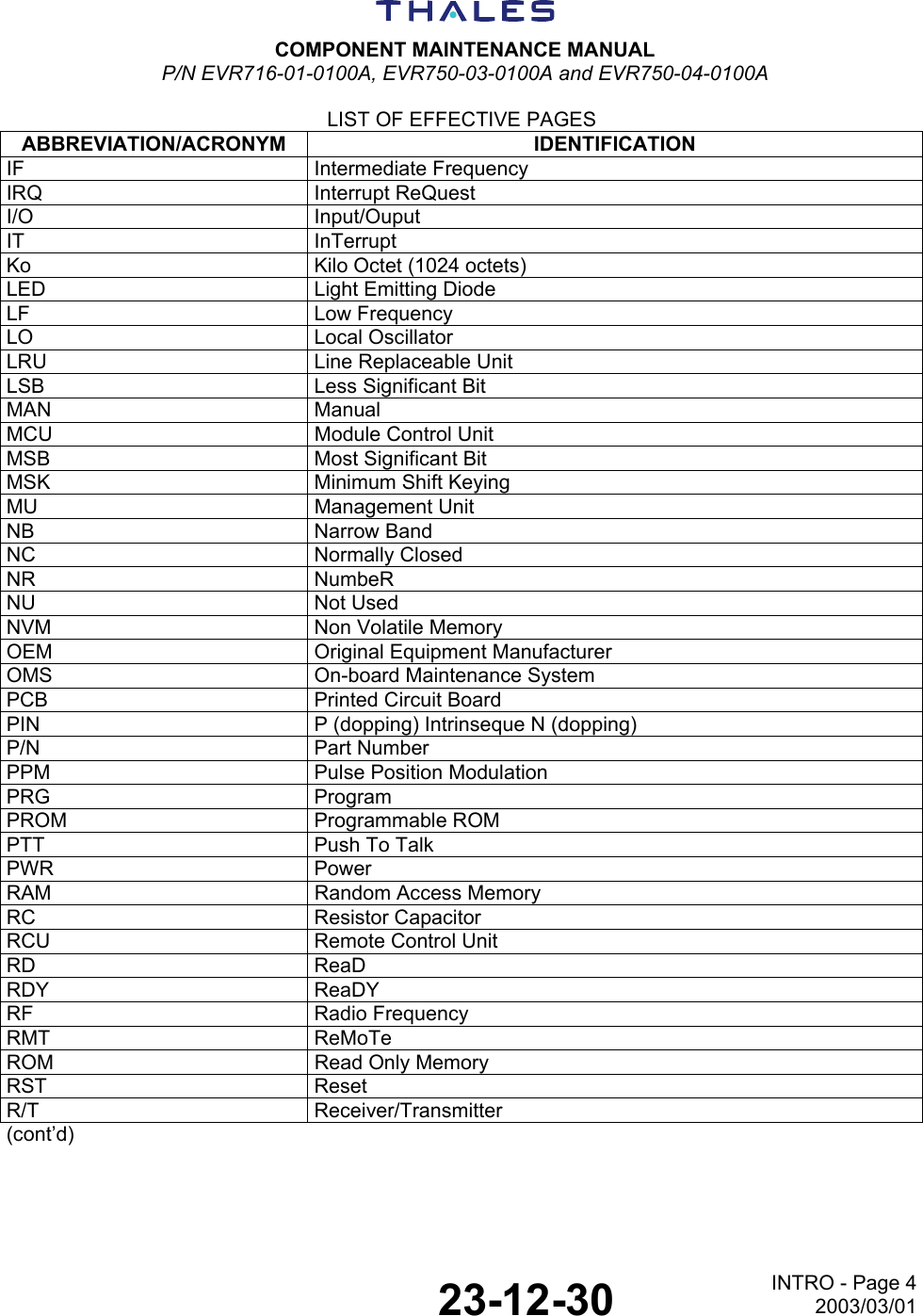
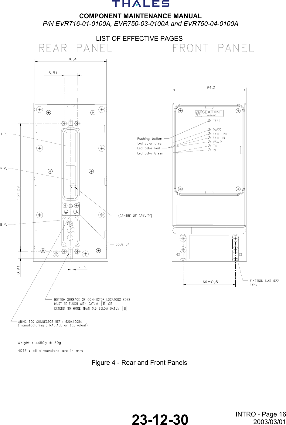
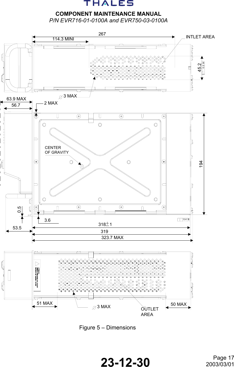
![COMPONENT MAINTENANCE MANUAL P/N EVR716-01-0100A and EVR750-03-0100A 23-12-30 Page 72003/03/01 CHARACTERISTICS SPECIFICATIONS TRANSMITTER ED-23B/DO-186A Class 3 and 5 ED-92 Class 7 Output power > 25 W Output power (mode 2) > 15 W Harmonics H2 < -16 dBm Hn < -26 dBm (n≥ 3) AF response Within 6 dB from 300 Hz to 2500 Hz Audio distortion < 10% Modulation level > 80 % for 0.25 Vrms at 1000 Hz Spectrum mask (8.33 kHz) For an audio frequency from 300 Hz to 10 kHz and an audio level attenuated by 10 dB/octave from 800 Hz to 10 kHz, referred to 70% modulation level < -45 dBc from ± 3.2 kHz to ± 5 kHz < -60 dBc from ± 5 kHz to ± 7 kHz < -70 dBc for frequency shift greater than ± 7 kHz Modulation ratio > 80% for a frequency of 1000 Hz at -10 dBm Data Input Frequency response Within 6 dB from 600 Hz to 6600 Hz Distortion < 10% for 80% modulation ratio over frequency range from 600 Hz to 6600 Hz RF Power rise time < 190µs RF Power release time < 190µs Symbol constellation error Error vector Magnitude (EVM) < 6% Adjacent channel power 1st ACP : < -18dBm 2nd ACP : < -28dBm 3rd ACP : < -38dBm Wide band noise < -53dBm Certification Pour EVR716-01-xxxxx et EVR750-03-xxxxx : DO160C/A2D1/YBA/BCMN/XXXXXXABAZZUZ/A2E2/XX Pour EVR750-04-xxxxx : DO160D Env.Cat.[(A2)(D1)Y]BAB[SMBC]XXXXXXAAAZZUZ[A2E2]XXA QAC1 NOTE: ”Nominal” relates to Standard Conditions. The first and last selectable 25 kHz channels are respectively: − 118.000 (F0 = 118.0000 MHz) − 136.975 (F0 = 136.9750 MHz)](https://usermanual.wiki/Thales-Communications/EVR750/User-Guide-333183-Page-31.png)