Thales Communications EVR750 AIRBORNE VHF DATA RADIO User Manual 333183
THALES Communications AIRBORNE VHF DATA RADIO 333183
CMM

COMPONENT MAINTENANCE MANUAL
P/N EVR716-01-0100A, EVR750-03-0100A and EVR750-04-0100A
23-12-30 TITLE Page 1/2
2003/03/01
LISTE DES RENVOIS
ATA
23-12-30
Fabricant
P/N
Date d'édition originale
2003/03/01
Date d'édition 2003/03/01

COMPONENT MAINTENANCE MANUAL
P/N EVR716-01-0100A, EVR750-03-0100A and EVR750-04-0100A
23-12-30 TS Page 1 of 1
2003/03/01
TRANSMITTAL SHEET
TO: HOLDERS OF COMPONENT MAINTENANCE MANUAL FOR EVR716 AND EVR750 ATA 23-
12-30.
FILING INSTRUCTIONS
− Revision No. P04 of the CMM replaces the revision No. 3.
− Revision No. 3 is deleted.

COMMUNICATIONS
F0057
FIRST ISSUE: JAN 15/98
Ref/Doc: 36708021-AC
REVISION No.: 4 23-12-30 TP Page 1/2
2003/03/01
COMPONENT MAINTENANCE MANUAL
(FOR USE WITH SEPARATE
ILLUSTRATED PARTS CATALOG)
PRELIMINARY
Enhanced VHF Radio
VHF Communications Transceiver
P/Ns: EVR716-01-0100A
EVR716-01-0200A
EVR750-03-0100A
EVR750-04-0100A
EVR750-04-0200A

COMPONENT MAINTENANCE MANUAL
P/N EVR716-01-0100A, EVR750-03-0100A and EVR750-04-0100A
LIST OF EFFECTIVE PAGES
23-12-30 ROR Page 1/2
2003/03/01
RECORD OF REVISIONS
INSERTED
REV.
No.
ISSUE
DATE DATE BY
1 JAN 15/99
2 MAY 21/99
3 2002/10/15
P04 2003/03/01
INSERTED
REV
ISSUE
DATE BY
INSERTED
REV
ISSUE
DATE BY

COMPONENT MAINTENANCE MANUAL
MMR TLS755
P/N: TLS755-XX-YYZZK
TITRE
Page 2/2
25 April 03
Error! Reference source not found.
INSERTED
REV.
No.
ISSUE
DATE DATE BY
COMPONENT MAINTENANCE MANUAL
P/N EVR716-01-0100A, EVR750-03-0100A and EVR750-04-0100A
LIST OF EFFECTIVE PAGES
23-12-30 RTR Page 1/2
2003/03/01
RECORD OF TEMPORARY REVISIONS
INSERTED REMOVED
TEMP.
REV.
No. ISSUE DATE DATE BY DATE BY
PAGE No.
1 JUN 30/99 2002/10/15 THALES 114, 117, 901
2 MAR 30/01 2002/10/15 THALES 3A, 3B
3 JUN 25/01 2002/10/15 THALES 4, 706

COMPONENT MAINTENANCE MANUAL
P/N EVR716-01-0100A, EVR750-03-0100A and EVR750-04-0100A
LIST OF EFFECTIVE PAGES
23-12-30 SBL Page 1/3
2003/03/01
SERVICE BULLETIN LIST
SERVICE
BULLETIN
NUMBER
R
E
V
INCLUDED
IN
REVISION
DATE
OF
INCORPORATION
TITLE
1
EVR716-23-01
2 3 2002/10/15 To increase the internal test filtering
during power switching.
To improve the general behaviour of
the sidetone, for CLIMAX and COSITE
configuration.
(P/Ns: EVR716-01-0100A/01-0200A).
2
EVR716-23-02
B
A
S
I
C
3 2002/10/15 To upgrade the actual Transmitter
Board (TX) to industrial level by a re-
layout of the printed circuit board.
(P/Ns: EVR716-01-0100A/01-0200A).
3
EVR716-23-03
B
A
S
I
C
3 2002/10/15 To upgrade the actual Receiver Board
(RX) to industrial level by a re-layout of
the printed circuit board.
(P/Ns: EVR716-01-0100A/01-0200A).
4
EVR716-23-04
B
A
S
I
C
3 2002/10/15 To upgrade the actual HIRF Board to
industrial level by a re-layout of the
printed circuit board.
(P/Ns: EVR716-01-0100A/01-0200A).
5
EVR716-23-05
1 3 2002/10/15 To correct some non-working units at
136.025 MHz Frequency due to the
disparity of the CR8 zener diode
regulating the 17V Power Supply of
MA21.
(P/Ns: EVR716-01-0100A/01-0200A).
6
EVR716-23-06
B
A
S
I
C
Not issued.
7
EVR716-23-07
B
A
S
I
C
3 2002/10/15 To provide the 8.33 KHz channelling
compatibility between VHF data radio
unit and the control panel on BOEING
B777.
(P/N: EVR716-01-0200A).

COMPONENT MAINTENANCE MANUAL
P/N EVR716-01-0100A, EVR750-03-0100A and EVR750-04-0100A
LIST OF EFFECTIVE PAGES
23-12-30 SBL Page 2/3
2003/03/01
SERVICE
BULLETIN
NUMBER
R
E
V
INCLUDED
IN
REVISION
DATE
OF
INCORPORATION
TITLE
8
EVR716-23-08
3 3 2002/10/15 To improve the interference response
due to COSITE Transmitter (especially
for ACARS transmissions).
To enhance the transmitter spectrum
at ± 75 kHz detected by the ground
stations.
To improve the squelch response at
the range limit.
To change the monitoring of the power
interrupt information.
To correct the management of a “busy
channel” during autotest.
To provide data link improvement for
received audio time establishment and
for SQP.
To provide the 8.33 kHz channelling
compatibility between VHF data radio
unit and control panel on BOEING 777
whatever the unit P/N is.
P/Ns: EVR716-01-0100A/01-0200A
9
EVR716-23-09
1 3 2002/10/15 To convert the EVR716 Radio into a
EVR750 “A” Radio.
Note: This service bulletin is not
included in this C.M.M.
Refer to SB No. 9 for technical
information.
This SB is only for EVR716 version:
01-0100A.
10
EVR716-23-10
Not issued.
11
EVR716-23-11
1 3 2002/10/15 To improve the reliability of the
EVR716 P/N: EVR716-01-0200A.
1
EVR7-23-01
1 3 2002/10/15 To improve the reliability of the
EVR716 P/N: EVR716-01-0100A
EVR750 P/N:EVR750-03-0100A
2
EVR7-23-02
1 3 2002/10/15 To adapt the receivers design to all
TCXO suppliers.To correct on some
units a random 400ms noise in the
headset when the PTT is released.
To check C180 polarity on the Tx
board.Applicable to P/N EVR716-01-
0100A and EVR750-03-0100A.

COMPONENT MAINTENANCE MANUAL
P/N EVR716-01-0100A, EVR750-03-0100A and EVR750-04-0100A
LIST OF EFFECTIVE PAGES
23-12-30 SBL Page 3/3
2003/03/01
SERVICE
BULLETIN
NUMBER
R
E
V
INCLUDED
IN
REVISION
DATE
OF
INCORPORATION
TITLE
1
EVR750-23-01
B
A
S
I
C
3 2002/10/15 To upgrade the existing transmitter
board (TX) by a re-layout of the printed
circuit board.
P/Ns: EVR750-03-0100A/03-0200A
2
EVR750-23-02
B
A
S
I
C
3 2002/10/15 To upgrade the existing receiver board
(RX) by a re-layout of the printed circuit
board.
P/Ns: EVR750-03-0100A/03-0200A
3
EVR750-23-03
B
A
S
I
C
3 2002/10/15 To upgrade the existing HIRF board by
a re-layout of the printed circuit board.
P/Ns: EVR750-03-0100A/03-0200A
4
EVR750-23-04
B
A
S
I
C
Not issued.

COMPONENT MAINTENANCE MANUAL
P/N EVR716-01-0100A, EVR750-03-0100A and EVR750-04-0100A
LIST OF EFFECTIVE PAGES
23-12-30 SILL Page 1/2
2003/03/01
SERVICE INFORMATION LETTER LIST
SERVICE
INFORMATION
LETTER No.
INCLUDED
IN
REVISION
DATE
OF
INCORPORATION TITLE
1 3 2002/10/15 Initial modifications status of power
Supply Unit (PSU), Transmitter Unit
(TX), Receiver Unit (RX), Data
Processing Unit (DPU) and HIRF Unit.
Applicable to P/Ns: EVR716-01-0100A
and EVR716-01-0200A.
1
EVR750-23-01
3 2002/10/15 Initial modifications status of EVR750
Transceiver.
Applicable to P/Ns: EVR750-03-0100A
and EVR750-03-0200A.
2
EVR750-23-02
3 2002/10/15 To adapt the receivers design to all
TCXO suppliers.
To correct on some units a random
400 ms noise in the headset when the
PTT is released.
To check C180 polarity on the
Transmitter Board.
P/Ns: EVR716-01-0X00A and
EVR750-03-0X00A.
SUBJECT
PAGE
DATE
SUBJECT
PAGE
DATE

COMPONENT MAINTENANCE MANUAL
P/N EVR716-01-0100A, EVR750-03-0100A and EVR750-04-0100A
LIST OF EFFECTIVE PAGES
23-12-30 SBL Page 2/3
2003/03/01
SUBJECT
PAGE
DATE
Title Page 1 2003/03/01
2 Blank
Record of 1 2003/03/01
Revisions 2 Blank
Record of 1 2003/03/01
Temporary 2 Blank
Revisions
List of 1 2003/03/01
Effective 2 Blank
Temporary
Revisions
Service 1 2003/03/01
Bulletin List 2 2003/03/01
3 2003/03/01
4 Blank
Service 1 2003/03/01
Information 2 Blank
Letter List
List of 1 2003/03/01
Effective 2 2003/03/01
Pages 3 2003/03/01
4 2003/03/01
5 2003/03/01
6 2003/03/01
7 2003/03/01
8 Blank
Table of 1 2003/03/01
Contents 2 2003/03/01
3 2003/03/01
4 2003/03/01
Introduction 1 2003/03/01
2 2003/03/01
3 2003/03/01
4 2003/03/01
SUBJECT
PAGE
DATE
5 2003/03/01
6 Blank
Description 1 2003/03/01
and 2 2003/03/01
Operation 3 2003/03/01
4 2003/03/01
5 2003/03/01
6 2003/03/01
7 2003/03/01
8 2003/03/01
9 2003/03/01
10 2003/03/01
11 2003/03/01
12 2003/03/01
13 2003/03/01
14 2003/03/01
15 2003/03/01
16 2003/03/01
17 2003/03/01
18 2003/03/01
19 2003/03/01
20 2003/03/01
21 2003/03/01
22 2003/03/01

COMPONENT MAINTENANCE MANUAL
P/N EVR716-01-0100A, EVR750-03-0100A and EVR750-04-0100A
LIST OF EFFECTIVE PAGES
23-12-30 LOT Page 1
2003/03/01
TABLE OF CONTENTS
SUBJECT PAGE
TRANSMITTAL SHEET.................................................................................................................1
RECORD OF REVISIONS ............................................................................................................1
RECORD OF TEMPORARY REVISIONS..................................................................................... 1
SERVICE BULLETIN LIST............................................................................................................1
SERVICE INFORMATION LETTER LIST .....................................................................................1
LIST OF EFFECTIVE PAGES.......................................................................................................1
TABLE OF CONTENTS ................................................................................................................1
INTRODUCTION ...........................................................................................................................1
1. General...............................................................................................................................1
2. Equipment Identification .....................................................................................................2
A. Generic Part Number....................................................................................................... 2
B. Front panel labels............................................................................................................2
3. Uncommon Abbreviations/Acronyms..................................................................................2
DESCRIPTION AND OPERATION ...............................................................................................1
1. Description..........................................................................................................................1
A. General............................................................................................................................1
B. Frontispiece.....................................................................................................................3
2. Function of Equipment........................................................................................................4
A. Characteristics.................................................................................................................5
B. Description.....................................................................................................................10
3. Operation..........................................................................................................................18
A. General..........................................................................................................................18
B. Wired Chassis Assembly (CHC)....................................................................................23

COMPONENT MAINTENANCE MANUAL
P/N EVR716-01-0100A, EVR750-03-0100A and EVR750-04-0100A
LIST OF EFFECTIVE PAGES
23-12-30 INTRO - Page 1
2003/03/01
INTRODUCTION
1. General
This Component Maintenance Manual includes maintenance instructions prepared in
accordance with Air Transport Association Specification Nr. 100 for the THALES
COMMUNICATIONS Enhanced VHF Radio. Parts lists are provided in a separate Illustrated
Parts Catalog ATA: 23-12-30 (Ref/Doc: 36708031).
In this issue, the CMM provides informations concerning the EVR716/750 versions.
This manual provides procedures for shop testing and repair. It presents detailed circuit theory
with emphasis on items which will be especially helpful for effective fault isolation. It contains
complete performance tests and adjustment procedures.
This Component Maintenance Manual provides shop verified procedures that will enable a
technician, unfamiliar with the equipment, to restore it to serviceable condition. The procedures
are prepared for the technician that performs shop work and not for the aircraft technician.
CAUTION: THE MATERIAL IN THIS MANUAL IS SUBJECT TO CHANGE. BEFORE
ATTEMPTING ANY MAINTENANCE OPERATION ON THE EQUIPMENT
COVERED IN THIS MANUAL, VERIFY THAT YOU HAVE COMPLETE AND
UP-TO-DATE PUBLICATIONS BY REFERRING TO THE APPLICABLE
PUBLICATIONS, SERVICE BULLETIN, SERVICE INFORMATION LETTER
INDEXES.
Refer to the Table of Contents for the page location of applicable sections.
A list of uncommon/acronyms abbreviations used in the manual is described in paragraph 2 of
the INTRODUCTION section. The manual will be revised as necessary to reflect current
information.
We welcome your comments concerning this manual. Although effort has been made to keep it
free of errors, some may occur. When reporting a specific problem, please describe it briefly
and include the manual part number, the paragraph or figure number, and the page number.
Send your comments to:
THALES AVIONICS
Aérodrome de Villacoublay
B.P59
78 141 VELIZY VILLACOUBLAY CEDEX
FRANCE
COMPONENT MAINTENANCE MANUAL
P/N EVR716-01-0100A, EVR750-03-0100A and EVR750-04-0100A
LIST OF EFFECTIVE PAGES
23-12-30 INTRO - Page 2
2003/03/01
2. Equipment Identification
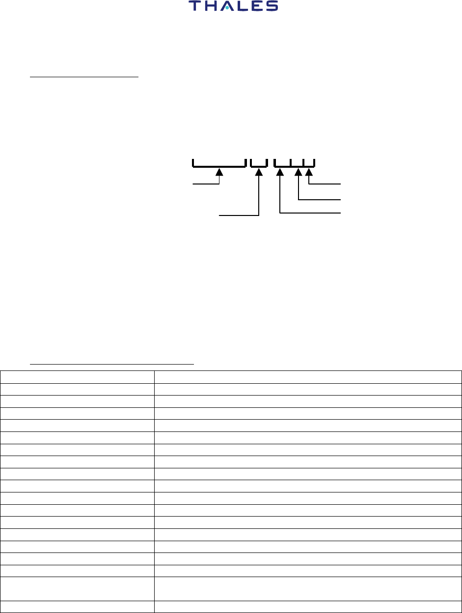
A. Generic Part Number
The part number has the following format (example).
EVR716 -01- 0200A
Family designation
Version of the equipment according to installed
Hardware evolution index
Software evolution index
Maintenance
Software version
B. Front panel labels
Different kinds of labels are stuck on the front panel of the EVR716/750 unit.
According of EVR716 or EVR750 unit versions, all labels are not similar.
For more information, refer to the Illustrated Parts Catalog, ATA: 23-12-30 (Ref/Doc:
36708031) Figures 1 and 1A for the localization on the front panel of the unit.
3. Uncommon Abbreviations/Acronyms
ABBREVIATION/ACRONYM IDENTIFICATION
ACARS Aircraft Communications Addressing and Reporting System
ADC Analog to Digital Converter
AF Audio Frequency
AGC Automatic Gain Control
AIN Analog INput
AM Amplitude Modulation
AMU Audio Management Unit
ANT ANTenna
ARINC Aeronautical Radio INCorporated
ATE Automatic Test Equipment
BCD Binary Coded Decimal
BER Bit Error Rate
BIT Built-In Test
BITE Built-In Test Equipment
BNC BiNary Code
BNR BiNaRy
CCITT Comité Consultatif International de Télécommunication et
Transmission
CDU Control Display Unit

COMPONENT MAINTENANCE MANUAL
P/N EVR716-01-0100A, EVR750-03-0100A and EVR750-04-0100A
LIST OF EFFECTIVE PAGES
23-12-30 INTRO - Page 3
2003/03/01
ABBREVIATION/ACRONYM IDENTIFICATION
CFDS Centralized Fault Display System
CHC CHassis Câblé (Wired Chassis)
CODEC COder/DECoder
CMC Centralized Maintenance Computer
CMU Communications Management Unit
CPT Counter
CPTT Control Push To Talk
CRT Cathode Ray Tube
CS Chip Select
CSMA Carrier Sense Multiple Access
CW Carrier Wave or Continuous Wave
DAC Digital to Analog Converter
D/A Digital/Analog
dBc DeciBel Carrier
dBm DeciBel referred to 1 Milliwatt
DC Direct Current
DF Design Function
DFIU Discrete Function Interface Unit
DFS Data Frequency System
DISP DISPlay
DPU Data Processing Unit
DSP Digital Signal Processor
D8PSK Differential 8 Phases Shift Keying
EEPROM Electrically Erasable PROM
EPLD Erasable Programmable Logical Device
EPROM Electrically Programmable ROM
ESDS ElectroStatic Discharge Sensitive
EVR Enhanced VHF Radio
EXT EXTernal
FET Field Effect Transistor
FIFO First In, First Out
FILT FILTer
FM Frequency Modulation
FO Oscillator Frequency
FT Functional Test
FW Failure Warning
GND GrouND
HF High Frequency
HIRF High Intensity Rejected Frequency
ICAO International Civil Aviation Organisation
(cont’d)

COMPONENT MAINTENANCE MANUAL
P/N EVR716-01-0100A, EVR750-03-0100A and EVR750-04-0100A
LIST OF EFFECTIVE PAGES
23-12-30 INTRO - Page 4
2003/03/01
ABBREVIATION/ACRONYM IDENTIFICATION
IF Intermediate Frequency
IRQ Interrupt ReQuest
I/O Input/Ouput
IT InTerrupt
Ko Kilo Octet (1024 octets)
LED Light Emitting Diode
LF Low Frequency
LO Local Oscillator
LRU Line Replaceable Unit
LSB Less Significant Bit
MAN Manual
MCU Module Control Unit
MSB Most Significant Bit
MSK Minimum Shift Keying
MU Management Unit
NB Narrow Band
NC Normally Closed
NR NumbeR
NU Not Used
NVM Non Volatile Memory
OEM Original Equipment Manufacturer
OMS On-board Maintenance System
PCB Printed Circuit Board
PIN P (dopping) Intrinseque N (dopping)
P/N Part Number
PPM Pulse Position Modulation
PRG Program
PROM Programmable ROM
PTT Push To Talk
PWR Power
RAM Random Access Memory
RC Resistor Capacitor
RCU Remote Control Unit
RD ReaD
RDY ReaDY
RF Radio Frequency
RMT ReMoTe
ROM Read Only Memory
RST Reset
R/T Receiver/Transmitter
(cont’d)

COMPONENT MAINTENANCE MANUAL
P/N EVR716-01-0100A, EVR750-03-0100A and EVR750-04-0100A
LIST OF EFFECTIVE PAGES
23-12-30 INTRO - Page 5/6
2003/03/01
ABBREVIATION/ACRONYM IDENTIFICATION
Rx Reception
SELCAL SELective CALling
SDI Source/Destination Identifier
SMD Surface Mounted Device
SRU Shop Replaceable Unit
SWR Standing Wave Ratio
TF Technical Function
TP Top Part
T/R Transmitter/Receiver
TRIG TRIGger
Tx Transmission
VCO Voltage Control Oscillator
VHF Very High Frequency
VMA Valid Memory Address
Vpp Volt Peak-to-Peak
Vrms Volt Root Mean Square Value
VSWR Voltage Standing Wave Ratio
WB Wide Band
WRN WaRNing
µP Microprocessor

COMPONENT MAINTENANCE MANUAL
P/N EVR716-01-0100A and EVR750-03-0100A
23-12-30 Page 1
2003/03/01
DESCRIPTION AND OPERATION
1. Description
A. General
This section gives the description of the EVR716/750 Enhanced VHF Radio (VHF
communications transceiver).
THALES Part-Number Features
EVR716-01-0100A
118 MHz -136.975 MHz frequency range. 25 kHz and
8.33 kHz channel spacing. Compliant with ICAO Annex
10 FM immunity. Conform to DO-178B and DO-160C
requirements. Fault memory. ACARS compatible
(analogue interface). 200 ms power drop-out
transparency. Software data loading via RS232 interface.
Airbus ABD0048 or Boeing D243W220 interface
maintenance interface selectable by pin programming
with Airbus ABD0048 maintenance interface by
default.
EVR716-01-0200A 118 MHz-136.975 MHz frequency range. 25 kHz and
8.33 kHz channel spacing. Compliant with ICAO Annex
10 FM immunity. Conforms to DO-178B and DO-160C
requirements. Fault memory. ACARS compatible
(analogue interface). 200 ms power drop-out
transparency. Software dataloading via RS232 interface.
Airbus ABD0048 or Boeing D243W220 interface
maintenance interface selectable by pin programming
with Boeing D243W220 maintenance interface by
default.
(cont’d) Table 1 - Part Numbers List

COMPONENT MAINTENANCE MANUAL
P/N EVR716-01-0100A, EVR750-03-0100A and EVR750-04-0100A
LIST OF EFFECTIVE PAGES
23-12-30 INTRO - Page 2
2003/03/01
THALES Part-Number Features
EVR750-03-0100A 118 MHz-136.975 MHz frequency range. 25 kHz and
8.33 kHz channel spacing. Compliant with ICAO Annex
10 FM immunity. Conforms to DO-178B and DO-160C
requirements. Fault memory. Analogue or Digital
Interface ACARS compatible (digital interface with
ATSU/CMU-mode A-). 200 ms power drop-out
transparency. Software dataloading via RS232
interface. Airbus ABD0048 or Boeing D243W201
interface maintenance. Interface selectable by pin
programming with Airbus ABD0048 maintenance
interface by default.
EVR750-04-0100A 118 MHz-136.975 MHz frequency range. 25 kHz and
8.33 kHz channel spacing. Compliant with ICAO Annex
10 FM immunity. Conforms to DO-178B and DO-160D
requirements. Fault memory. Analogue or Digital
Interface ACARS compatible (digital interface with
ATSU/CMU-mode A-). 200 ms power drop-out
transparency. Data transmission (31.5kb/sec) with the
VDL mode 2 protocol (D8PSK modulation and CSMA
access according to ARINC 750 and SARPS VDL2).
Interface with ATSU/CMU mode 2. Software
dataloading via RS232 interface. Airbus ABD0048 or
Boeing D243W201 interface maintenance. Interface
selectable by pin programming with Airbus ABD0048
maintenance interface by default.
EVR750-04-0200A 118 MHz-136.975 MHz frequency range. 25 kHz and
8.33 kHz channel spacing. Compliant with ICAO Annex
10 FM immunity. Conforms to DO-178B and DO-160D
requirements. Fault memory. Analogue or Digital
Interface ACARS compatible (digital interface with
ATSU/CMU-mode A-). 200 ms power drop-out
transparency. Data transmission (31.5kb/sec) with the
VDL mode 2 protocol (D8PSK modulation and CSMA
access according to ARINC 750 and SARPS VDL2).
Interface with ATSU/CMU mode 2. Software
dataloading via RS232 interface. Airbus ABD0048 or
Boeing D243W201 interface maintenance. Interface
selectable by pin programming with Boeing D243W201
maintenance interface by default.
Table 1 - Part Numbers List
COMPONENT MAINTENANCE MANUAL
P/N EVR716-01-0100A and EVR750-03-0100A
23-12-30 Page 3
2003/03/01
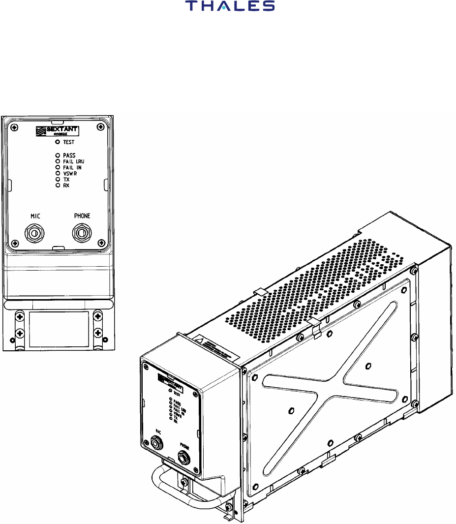
B. Frontispiece
Figure 1 - EVR716/750 Unit

COMPONENT MAINTENANCE MANUAL
P/N EVR716-01-0100A, EVR750-03-0100A and EVR750-04-0100A
LIST OF EFFECTIVE PAGES
23-12-30 INTRO - Page 4
2003/03/01
2. Function of Equipment
The airborne equipment, called EVR (Enhanced VHF Radio), is a VHF communications
transceiver operating in the aeronautical band (118 MHz to 137 MHz or 118 MHz to 152 MHz),
used by Air Transport Aircraft as a primary equipment for communications with the ground air
traffic control infrastructure (in continental areas) or for communications between aircraft (relay,
emergency).
The basic version of EVR-716 (EVR716-01-xxxxx) and EVR750 (EVR750-03-xxxxx and
EVR750-04-xxxxx) operates in the 118 MHz-137 MHz aeronautical band and a specific version
for frequency band extension up to 152 MHz is also available (EVR716-02-xxxxx).
Aboard the aircraft, the EVR716/750 transceiver can operate with the following equipment:
− a Frequency Selection System which can be an RCU (Radio Control Unit or control unit)
or an RMP (Radio Management Panel) to agree with the aircraft configuration,
− an ACARS MU (Management Unit, ARINC 724) or a CMU (Communications
Management Unit, ARINC 758),
− an Audio Management Unit (AMU),
− a maintenance computer: OMS (ARINC 624) or CFDS (ARINC 604),
− a SELCAL decoder system,
− a ATSU/CMU mode 2,
− a VHF antenna.
The EVR716 transceiver operates according the following modes of operation:
− Mode 0A: transmits/receives voice signals in one-way mode with 25 kHz channels
spacing, Amplitude Modulation and Double Side Bands,
− Mode 0B: transmits/receives voice signals in one-way mode with the channels 8.33 kHz
channels spacing, Amplitude Modulation and Double Side Bands,
− Mode 1A: transmits/receives data signals in one-way mode with AM-MSK modulation,
MSK modulation being performed externally in the (C) MU (standard ACARS mode). The
signal rate is 2.4 kb/sec. with the 25 kHz apart channels spacing.
The EVR750 transceiver operates according to the same modes as EVR716 (0A/0B/1A) and in
addition according to the following mode:
− Mode 1C: transmits/receives data signals in one-way mode with AM-MSK modulation,
MSK modulation being performed internally. The signal rate is 2.4 kb/sec. with the 25 kHz
apart channels spacing.
− Mode 2: transmits/receives data signals in one-way mode with D8PSK modulation. The
signal rate is 31.5 kb/sec with the 25 kHz apart channel spacing.

COMPONENT MAINTENANCE MANUAL
P/N EVR716-01-0100A and EVR750-03-0100A
23-12-30 Page 5
2003/03/01
A. Characteristics
(1) Electrical characteristics
CHARACTERISTICS SPECIFICATIONS
GENERAL
Operational modes Voice/25 kHz (0A)
Voice/8.33 kHz (0B)
Data AM/MSK (1A) (with external modem)
Data AM/MSK (1C) (with internal modem)
Data D8PSK (2)
Power requirements 28 VDC/180 W
Mode 2 :28VDC/210W
Form factor 3 MCU, ARINC Specification 600 i.e.
200x94x387.5 (mm)
Weight 4450 g ± 50 g
Operating Temperature
Storage Temperature
-25 °C to +70 °C (+13°F to +158°F)
-55 °C to +85 °C (-67°F to +185°F)
Over pressure decompression In accordance with DO-160C, section 4.6, category A2
and D1 (Cf: SSS and DDP) (DO-160D for EVR750-04-
xxxxx)
Vibrations In accordance with DO-160C, section 8, category B
(DO-160D for EVR750-04-0x00A)
Electromagnetic compatibility In accordance with DO-160C, section 15, 16, 17, 18, 19,
20, 21 and 22. (DO-160D for EVR750-04-xxxxx)
Frequency control Serial digital in accordance with ARINC 429
Frequency range 117.975 MHz to 137.000 MHz
Channel spacing 25 kHz and 8.33 kHz
Frequency stability < ± 5 ppm
Duty cycle Continuous transmission (with ARINC 600 cooling
system).
Duty cycle of 20% (1mn/4mn) with natural convection
Channel Switching Less than 60 ms
Transmit to receive switching
time
Less than 50 ms in mode 0A, 0B, 1A, 1C
Less than 1.5 ms in mode 2
Receive to transmit switching
time
Less than 50 ms in mode 0A, 0B, 1A, 1C
Less than 1.5 ms in mode 2
(cont’d)

COMPONENT MAINTENANCE MANUAL
P/N EVR716-01-0100A, EVR750-03-0100A and EVR750-04-0100A
LIST OF EFFECTIVE PAGES
23-12-30 INTRO - Page 6
2003/03/01
CHARACTERISTICS SPECIFICATIONS
RECEIVER
ED-23B/DO-186A Class C and E
ED-92 Class F
Sensitivity (modes 0A & 0B) For a wanted signal of -106 dBm, modulated 1kHz/30%,
(S+N)/N* is greater than 6 dB (nominal).
(*): CCITT weighted
Sensitivity (mode 2) Better than –98dBm to get a BER (non corrected)
better than 1.10-3
Selectivity (mode 0A) > ± 9 kHz at 6 dB bandwidth
< ± 17 kHz at 60 dB bandwidth
< ± 25 kHz at 70 dB bandwidth
Selectivity (mode 0B) > ± 2.78 kHz at 6 dB bandwidth
< ± 7.37 kHz at 60 dB bandwidth
Adjacent channel rejection (mode 2) Better than 44dB to get a BER better than 1.10-3
Co-channel interference (mode 2) Co-channel interference ratio better than 20dB to get a
BER better than 1.10-3
Dynamic Range (mode 2) From -98dBm up to -7dBm to get a BER better than 1.10-3
Strong Signals within the VHF range
(mode 2)
Better than -27dBm to get a BER better than 1.10-3
Cross modulation Unwanted signal level (1 kHz/50%) to obtain – 10 dB
referred to a signal of –87 dBm (1 kHz/50%):
- at ± 25 kHz > – 20 dBm
- at ± 50 kHz > – 15 dBm
- at ± 100 kHz > – 10 dBm
AGC regulation Within 3 dB (-93 dBm to -13 dBm input); no more than
6 dB (-101 dBm to +1 dBm)
Audio output 10 mW (adjustable from 5 mW to 40 mW) into 600 ohms
(± 20%) resistive load for -53 dBm signal modulated 30%
at 1000 Hz
Audio output frequency response Within 6 dB from 300 Hz to 2500 Hz better than -20 dB at
3750 Hz
Audio output harmonic distortion Not to exceed < 3% for -53 dBm signal modulated 30% at
1000 Hz
Undesired responses < 80 dB
Intermodulation (FM immunity) as per ARINC 716 section 3.6.7.5
Output level 0.5 Vrms (min.) into 600 ohms (± 20%) resistive load
Selcal/Data
Output
Frequency
response
Selcal (mode Voice):
< 3 dB from 312 Hz to 1200 Hz
AM-MSK (mode data)
< ± 6 dB from 300 Hz to 6600 Hz
Distortion < 3% for a signal of -53 dBm, modulated 30% at 1000 Hz
(cont’d)

COMPONENT MAINTENANCE MANUAL
P/N EVR716-01-0100A and EVR750-03-0100A
23-12-30 Page 7
2003/03/01
CHARACTERISTICS SPECIFICATIONS
TRANSMITTER
ED-23B/DO-186A Class 3 and 5
ED-92 Class 7
Output power > 25 W
Output power (mode 2) > 15 W
Harmonics H2 < -16 dBm
Hn < -26 dBm (n≥ 3)
AF response Within 6 dB from 300 Hz to 2500 Hz
Audio distortion < 10%
Modulation level > 80 % for 0.25 Vrms at 1000 Hz
Spectrum mask (8.33 kHz) For an audio frequency from 300 Hz to 10 kHz and an audio
level attenuated by 10 dB/octave from 800 Hz to 10 kHz,
referred to 70% modulation level
< -45 dBc from ± 3.2 kHz to ± 5 kHz
< -60 dBc from ± 5 kHz to ± 7 kHz
< -70 dBc for frequency shift greater than ± 7 kHz
Modulation
ratio
> 80% for a frequency of 1000 Hz at -10 dBm
Data Input Frequency
response
Within 6 dB from 600 Hz to 6600 Hz
Distortion < 10% for 80% modulation ratio over frequency range from
600 Hz to 6600 Hz
RF Power rise time < 190µs
RF Power release time < 190µs
Symbol constellation error Error vector Magnitude (EVM) < 6%
Adjacent channel power 1st ACP : < -18dBm
2nd ACP : < -28dBm
3rd ACP : < -38dBm
Wide band noise < -53dBm
Certification Pour EVR716-01-xxxxx et EVR750-03-xxxxx :
DO160C/A2D1/YBA/BCMN/XXXXXXABAZZUZ/A2E2/XX
Pour EVR750-04-xxxxx :
DO160D
Env.Cat.[(A2)(D1)Y]BAB[SMBC]XXXXXXAAAZZUZ[A2E2]X
XA
QAC1
NOTE: ”Nominal” relates to Standard Conditions.
The first and last selectable 25 kHz channels are respectively:
− 118.000 (F0 = 118.0000 MHz)
− 136.975 (F0 = 136.9750 MHz)

COMPONENT MAINTENANCE MANUAL
P/N EVR716-01-0100A, EVR750-03-0100A and EVR750-04-0100A
LIST OF EFFECTIVE PAGES
23-12-30 INTRO - Page 8
2003/03/01
The first and last selectable 8.33 kHz channels are respectively:
− 118.005 (F0 = 118.0000 MHz)
− 136.990 (F0 = 136.9917 MHz)

COMPONENT MAINTENANCE MANUAL
P/N EVR716-01-0100A and EVR750-03-0100A
23-12-30 Page 9
2003/03/01
(2) Environmental Certification
The EVR716/750 Transceiver meets the environmental conditions of the Radio
Technical Commission for Aeronautics (RTCA) document number DO-160C,
”Environmental Conditions and Test Procedures for Airline Electronic/electrical
Equipment and Instruments”.(DO-160D for EVR750-04-xxxxx).
A2 D1 /BAB /SMBC /X X X X X X A A A Z Z U Z /A2E2 /X X
EXPLOSION
WATERPROOFNESS
HYDRAULIC FLUID
SAND AND DUST
FUNGUS RESISTANCE
SALT SPRAY
VIBRATION
HUMIDITY
TEMPERATURE
AND ALTITUDE
LOSS OF COOLING
SYSTEM
TEMPERATURE
VARIATION
ICING
LIGHTNING INDIRECT
EFFECT
LIGHTNING DIRECT
EFFECT
EMISSION OF RADIO
FREQUENCY ENERGY
RADIO FREQUENCY
SUSCEPTIBILITY
INDUCED SIGNAL
SUSCEPTIBILITY
AUDIO FREQUENCY
CONDUCTED
SUSCEPTIBILITY
VOLTAGE SPIKES
POWER UNIT
MAGNETIC EFFECT
NOT
APPLICABLE
/A
ELECTROSTATIC
DISCHARGE
Figure 2 - Environmental Certification Categories

COMPONENT MAINTENANCE MANUAL
P/N EVR716-01-0100A, EVR750-03-0100A and EVR750-04-0100A
LIST OF EFFECTIVE PAGES
23-12-30 INTRO - Page 10
2003/03/01
B. Description
See Figure 3.
The EVR716/750 appears as a 3 MCU form box.
The EVR716/750 transceiver has the operating subassemblies (SRU) below:
− a receiver module
− a transmitter module
− a power supply module
− a Data Processing unit (DPU module)
− an HIRF module
− a power storage module (behind the rear panel)
− a wired chassis
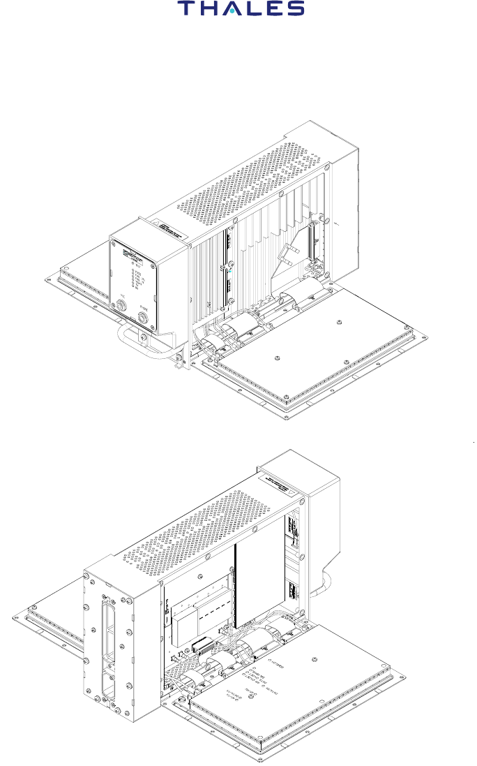
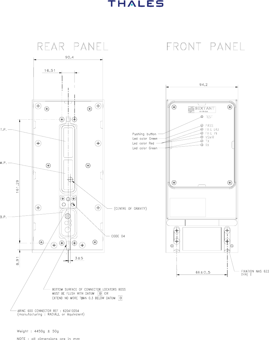
The EVR716/750 transceiver is built with a center chassis which holds (See Figure 4):
− a front panel assembly which hold the LED type indicators, a pushbutton for the
triggered test and the headset and microphone connectors. The six indicators are:
⋅ ”FAIL LRU” (red)
⋅ ”FAIL IN” (red)
⋅ ”PASS” (green)
⋅ ”VSWR” (red)
⋅ ”Tx” (green)
⋅ ”Rx” (green)
− on left side, the receiver module,
− on right side, the DPU module,
− on the center part, the Power Supply module and the Transmitter module.
− a rear panel with power supply, antenna input, inputs/outputs (discretes, ARINC
buses) and ATE (Automatic Test Equipment) interface.
The rear connector has the three parts below:
− the 60-way Middle Part (MP) with all the transceiver inputs (discretes, ARINC
buses),
− the 60-way Top Part (TP) with the contacts used for the ATE,
− the Bottom Part (BP) with the power supply contacts and the antenna coaxial
connector.

COMPONENT MAINTENANCE MANUAL
P/N EVR716-01-0100A and EVR750-03-0100A
23-12-30 Page 11
2003/03/01
(1) Electrical interfaces
NOTE:
Hi = High
Lo = Low
LS = Low Speed
HS = High Speed
(a) Middle Part connector
CONNECTOR/PIN SIGNAL NAME
MPA1
MPB1
MPC1
MPD1
Mike Input Hi
“ Lo
“ PTT
Key Event
MPA2
MPB2
MPC2
MPD2
Max Trans cutoff
Mike Input (Ground)
Data Loader Input A
“ B
MPA3
MPB3
MPC3
MPD3
Optional Hi
(Remote Squelch) ARM
Lo (GND)
DC Ground
MPA4
MPB4
MPC4
MPD4
Self Test Discrete
Audio Ground (Ground)
Data Loader Output A
“ B
MPA5
MPB5
MPC5
MPD5
Data Link Input HI
” Lo
Reserved for ARNIC 716 compatibility
8.33 kHz program for ARINC 716 compatibility
MPA6
MPB6
MPC6
MPD6
Data from OMS/CFDS # 1 input Port A A LS
” ” ” B
Data from OMS/CFDS# 2 input Port B A LS
” ” ” B
MPA7
MPB7
MPC7
MPD7
Freq./Func: Select A LS
Data I/P Port B B
Voice/Data Select
Data key line
(cont’d)
MPA8
MPB8
MPC8
MPD8
Reserved
Data loader enable
Reserved
Return (DC Ground)
MPA9 SDI code input
HS
HS

COMPONENT MAINTENANCE MANUAL
P/N EVR716-01-0100A, EVR750-03-0100A and EVR750-04-0100A
LIST OF EFFECTIVE PAGES
23-12-30 INTRO - Page 12
2003/03/01
CONNECTOR/PIN SIGNAL NAME
MPB9
MPC9
MPD9
SDI code input
Ground
Reserved for AGC
MPA10
MPB10
MPC10
MPD10
Program common
Reserved
Data to both CMUs Output port A HS
” ” ” B
MPA11
MPB11
MPC11
MPD11
Freq./Funct. Select Data I/P Port A A LS
” ” ” B
Maintenance interface software pin programming
Data select discrete
MPA12
MPB12
MPC12
MPD12
Data from CMU#1 Input Port A A HS
” ” ” B
Data from CMU#2 Input Port B A LS
” ” ” B
MPA13
MPB13
MPC13
MPD13
Selcal audio and Data output HI
” ” ” Lo
Squelch disable
Squelch disable return (Ground)
MPA14
MPB14
MPC14
MPD14
Maintenance interface software pin programming
Ground/air discrete
Data to OMS or CFDS Output port A LS
” ” ” B
MPA15
MPB15
MPC15
MPD15
Audio/sidetone output HI
” Lo
Muting output
Muting return (Ground)

COMPONENT MAINTENANCE MANUAL
P/N EVR716-01-0100A and EVR750-03-0100A
23-12-30 Page 13
2003/03/01
(b) Top Part connector
CONNECTOR/PIN SIGNAL NAME
TPA1
TPB1
TPC1
TPD1
MANUFACTURER IDENTIFIER
MANUFACTURER
RESERVED
RESERVED
TPA2
TPB2
TPC2
TPD2
COMMON
NOT USED
TPA3
TPB3
TPC3
TPD3
NOT USED
NOT USED
NOT USED
NOT USED
TPA4
TPB4
TPC4
TPD4
NOT USED
NOT USED
NOT USED
NOT USED
TPA5
TPB5
TPC5
TPD5
SELECT MODE ATE
TX 232A
DC GROUND
RX 232A
TPA6
TPB6
TPC6
TPD6
LED A1
LED A2
LED A3
LED A4
TPA7
TPB7
TPC7
TPD7
LED A5
RESERVED FOR AGC
RESERVED
WRITTEN
TPA8
TPB8
TPC8
TPD8
P5VT
P15VT
M15VT
NOT USED
TPA9
TPB9
TPC9
TPD9
RESPUATE1
RESPUATE2
NOT USED
NOT USED
TPA10
TPB10
TPC10
TPD10
BLOSQLT
CANOCT
COMPRESSOR-ON/OFF-INPUT
RESERVED
TPA11 TO TPD15 NOT USED

COMPONENT MAINTENANCE MANUAL
P/N EVR716-01-0100A, EVR750-03-0100A and EVR750-04-0100A
LIST OF EFFECTIVE PAGES
23-12-30 INTRO - Page 14
2003/03/01
(c) Bottom Part connector
CONNECTOR/PIN SIGNAL NAME
BP1
BP2
BP3
BP4
BP5
ANTENNA RF
POWER INPUT + 28 VDC
SPARE
POWER INPUT GROUND
NOT USED
(d) Pin programming for maintenance software selection
− P/N EVR 716/750 with BOEING maintenance interface by default:
EVR7xx-0x-0200A.
− P/N EVR716750 with AIRBUS maintenance interface by default:
EVR7xx-0x-0100A.
Pin Programming for maintenance software
selection
Maintenance Software
selected
MC11 MA14
0 0 Airbus
0 1* Boeing
1* 0 Airbus
1* 1* Default
* or not wired.
COMPONENT MAINTENANCE MANUAL
P/N EVR716-01-0100A and EVR750-03-0100A
23-12-30 Page 15
2003/03/01
Figure 3 - SRU Location
COMPONENT MAINTENANCE MANUAL
P/N EVR716-01-0100A, EVR750-03-0100A and EVR750-04-0100A
LIST OF EFFECTIVE PAGES
23-12-30 INTRO - Page 16
2003/03/01
Figure 4 - Rear and Front Panels
COMPONENT MAINTENANCE MANUAL
P/N EVR716-01-0100A and EVR750-03-0100A
23-12-30 Page 17
2003/03/01
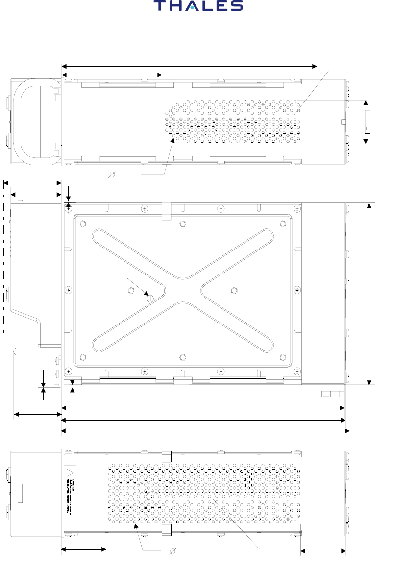
INTLET AREA
3 MAX
114.3 MINI
267
56.7
63.9 MAX
2 MAX
194
318 1
+
319
323.7 MAX
0.4 B
CENTER
OF GRAVITY
0.5 W
45.2
50 MAX
OUTLET
AREA
3 MAX
51 MAX
53.5
0.5
3.6
Figure 5 – Dimensions

COMPONENT MAINTENANCE MANUAL
P/N EVR716-01-0100A, EVR750-03-0100A and EVR750-04-0100A
LIST OF EFFECTIVE PAGES
23-12-30 INTRO - Page 18
2003/03/01
3. Operation
A. General
The primary function of the EVR716/750 transceiver is to provide voice and data
communications for Air Transport Aircraft, in the aeronautical band (118 MHz to
137 MHz).
The EVR716/750 transceiver operates in the voice and data modes given in the ARINC
716/750 specifications, that is for the voice modes: Amplitude Modulation with Double
Side Bands, with the channels 25 kHz (0A mode) or 8.33 kHz (0B mode) apart; and in
data mode: ACARS mode with an external modem. (internal modem for EVR-750) and
VDL Mode 2 (D8PSK).
MODE CHARACTERISTICS
0A Analog voice transmission
25 kHz
0B Analog voice transmission
8.33 kHz
1A Data, 25 kHz channel
AM-MSK modulation (2.4 kb/sec.)
External modem, CSMA access
ACARS protocol (analog interface for digital interface
with ATSU/CMU for EVR-750).
1C Data, 25 kHz channel
AM-MSK modulation (2.4 kb/sec.)
Internal modem, ACARS protocol (analog interface with
ATSU/CMU).
2 Data, 25 kHz channel
D8PSK modulation (bit rate 31.5kb/sec, symbol rate
10.5 kbauds) Access to the channel :CSMA non
adaptive p-persistent Interface with ATSU/CMU
through link ARINC 429 high speed.
Table 2 - Modes of Operation

COMPONENT MAINTENANCE MANUAL
P/N EVR716-01-0100A and EVR750-03-0100A
23-12-30 Page 19
2003/03/01
The EVR716/750 transceiver has seven subassemblies (SRU) which can be replaced in
a maintenance shop. These are:
Name Short name
WIRED CHASSIS CHC
HIRF module HIRF
RECEIVER Module REC
TRANSMITTER Module EME
DPU Module DPU
POWER SUPPLIES Module ALM
POWER STORAGE module PST
Table 3 - SRU of EVR716/750
The primary functions of an SRU are known as the Design Functions (DF).
Each function of a design function is known as a Technical Function (TF). An TF is a set
of components related to a primary component.
The functions are identified by the short name (mnemonic) of SRU and the short names
of the design function and technical function.
Example: SRU_DF_TF
HIRF_HIRF_RECIN
SRU
DESIGN FUNCTION
(
DF
)
DESIGN FUNCTION
(
DF
)
DESIGN FUNCTION
(
DF
)
DESIGN FUNCTION
(
DF
)
TECHNICAL FUNCTION (TF)
TECHNICAL FUNCTION (TF)
TECHNICAL FUNCTION (TF)
TECHNICAL FUNCTION (TF)
TECHNICAL FUNCTION (TF)
TECHNICAL FUNCTION (TF)
TECHNICAL FUNCTION (TF)
TECHNICAL FUNCTION (TF)
TECHNICAL FUNCTION (TF)

COMPONENT MAINTENANCE MANUAL
P/N EVR716-01-0100A, EVR750-03-0100A and EVR750-04-0100A
LIST OF EFFECTIVE PAGES
23-12-30 INTRO - Page 20
2003/03/01
Figure 6 - Organization of Functions
COMPONENT MAINTENANCE MANUAL
P/N EVR716-01-0100A and EVR750-03-0100A
23-12-30 Page 21
2003/03/01
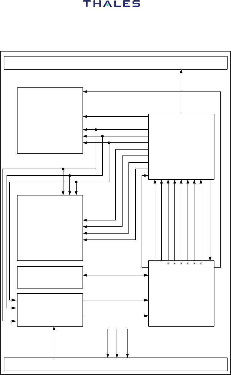
The next block diagrams show the connections between all the subassemblies of the
EVR716/750:
FRONT PANEL
Power Supplies
Module
+28V Network
REAR CONNECTOR
ALM
PP5V
Receiver
Module
REC
PP5V
R_SYN_P (10 MHz)
PP15V
PM15V
PP21V
PP16V
PRESET
PPOW_1
PPOW_2
PPOWINT
Transmitter
Module
EME
DPU
Module
GST
PP28V
PM15V
PP15V
PP5V
PP21V
PRESET
PPOW_1
PPOW_2
PPOWINT
A1Z-SA-E
HIRF
Module
HIRF
Power Storage
Module
PST
PP50V
PP28VPA
PP28VPS
PP5VT
PP15VT
PM15VT
Figure 7 - Power Supply Connections
COMPONENT MAINTENANCE MANUAL
P/N EVR716-01-0100A, EVR750-03-0100A and EVR750-04-0100A
LIST OF EFFECTIVE PAGES
23-12-30 INTRO - Page 22
2003/03/01
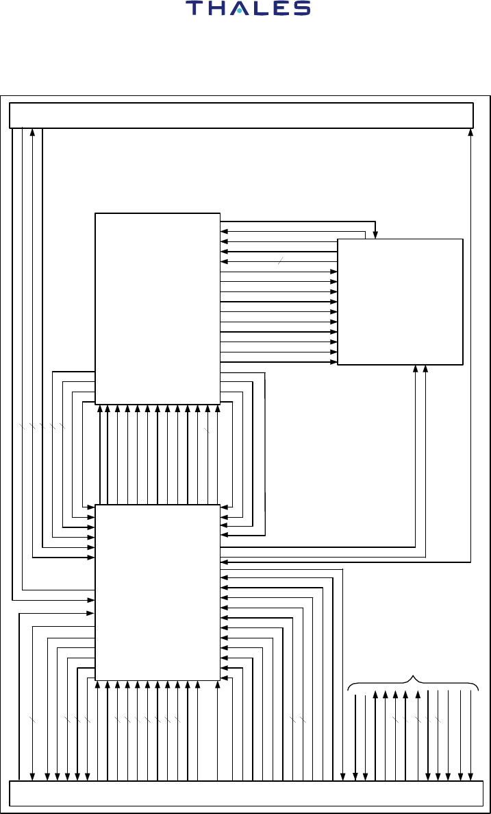
FRONT PANEL
RAGCFST
REAR CONNECTOR + HIRF
Receiver
Module
REC
Transmitter
Module
EME
DPU
Module
DPU
RAGCWB
FRSQL
FMIKIN
FDTIN
RDTOUT
RVOOUT
RLO2LEV
RANTEN
LED_ATE
MTX232A
FRX232A
FMODEA
FWRITEN
FOT-ID
FSDI
FSLFTST
FSLTDT
FMNTID2
FMNTID1
FDATSEL
FAIRGRO
FDATLOD
FTXCUTO
FVODAT
FDLR
FCMC2
FCMC1
FCMU2
FCMU1
FDFS2
FDFS1
FDATKEY
FPTTKEY
MCMU
MCMC
MDL
MMUTING
MKEVENT
D_LF2
D_LF1
Receiver Module
MALT_TX
MALT_RX
MPROTEC
MTST_TX
MTST_RX
MNB_WB
MAN_D8
MVO_DAT
MCLKSER
MDATSER
MSTRO
RHEA
RBLOSQL
RCANOC
Logic tests
REXT-LO-HI
CMIK (R/T LF)
RSQL-OB
MLEDs
CPUSHB (Push-button)
RSYNDPU
R-LF3
R-LF4
Logic tests
TLFREC (LF)
TSIDETONE
TVHFT_R
R_SYN_T
MTST_TX
MTST_RX
MVO_DAT
MAM_D8
MNB_WB
MSTRO_T
MDATSER
MCLKSER
MPROTEC
MALT_TX
2
2
2
2
2
2
2
2
2
2
5
2
3
2
2
2
2
2
11
2(Audio Side tone)
4
6
4
A2Z-SA-E
CPTT
RAGCIF
RCANOC
RBLOSQL
CMIK
2
2
RHEA
FCOMP
Figure 8 - Signal Connections
COMPONENT MAINTENANCE MANUAL
P/N EVR716-01-0100A and EVR750-03-0100A
23-12-30 Page 23
2003/03/01
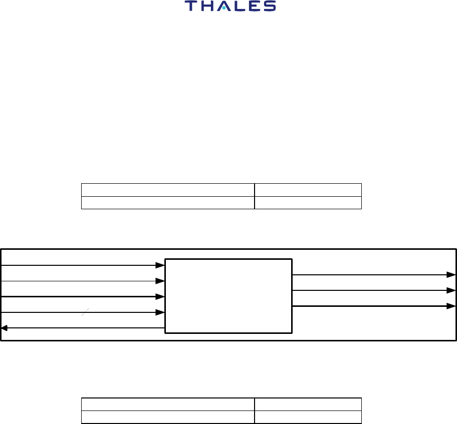
B. Wired Chassis Assembly (CHC)
The wired chassis assembly does the functions below (without the mechanical functions):
− electrical interface between the internal functions of the equipment,
− dissipation of the heat caused by the operation of the electrical subassemblies,
− control of a serviceability test using six LEDs.
Ribbon cables connect the cards and the rear connector.
The wired chassis assembly has one Design Function (DF):
Name Short name
Front Panel CHC_FAV
Table 4 - Wired Chassis
Design Function
CHC
Front Panel
CHC_FAV
+5V
LO_MICRO_FACE_AV
HI_MICRO_FACE_AV
Triggered Test (PB)
HI_HEADPHONE_FACE_AV
LEDs Control
LO_HEADPHONE_FACE_AV
6
B1Z-SA-E
Alternat phonie
Figure 9 - Wired Chassis (CHC)
Block Diagram
This DF has one TF:
Name Short name
Front Panel CHC_FAV_FAV
Table 5 - Front Panel
Technical Function
This TF is the front panel of the EVR716/750 transceiver. It has six LED type indicators,
one ”TEST” pushbutton to trigger the tests. There are also two jack type sockets, one for
the headset and the other for the microphone (See Figure 4).

COMPONENT MAINTENANCE MANUAL
P/N EVR716-01-0100A, EVR750-03-0100A and EVR750-04-0100A
LIST OF EFFECTIVE PAGES
23-12-30 INTRO - Page 24
2003/03/01
The six indicators are:
− ”FAIL LRU” (red): lights on when the continuous or/and triggered tests (init or
pushbutton) find a malfunction in the transceiver and not in the
inputs (discrete or ARINC 429 bus).
− ”FAIL IN” (red): lights on when the EVR716/750 transceiver finds a malfunction
in the inputs (DFS ARINC 429 bus).
− ”PASS” (green): lights on when the continuous or/and triggered tests (init or
pushbutton) do not find any malfunctions.
− ”VSWR” (red): lights on when the transceiver measures an VSWR larger
than 2:1.
− ”Tx” (green): lights on when the transceiver transmits.
− ”Rx” (green): lights on when the transceiver is in receive mode.
The front panel connections are as follows:
Signal Input/Output SRU_DF_TF
LED Tx control I DPU_G/M_AFFAV
LED Tx control I DPU_G/M_AFFAV
LED VSWR control I DPU_G/M_AFFAV
LED PASS control I DPU_G/M_AFFAV
LED FAIL LRU control I DPU_G/M_AFFAV
LED FAIL IN control I DPU_G/M_AFFAV
Front Panel Test (PB) O DPU_G/M_DECTEST
+5V voltage I REC_ALM_+ 5V
HI_CASQUE_FACE_AV (RHEA_H) I REC_AIGUI_BFAUDIO
LO_CASQUE_FACE_AV (RHEA_L) I REC_AIGUI_BFAUDIO
HI_MICRO_FACE_AV (CMIK_H) O REC_AIGUI_AUDIOIN
LO_MICRO_FACE_AV (CMIK_L) O REC_AIGUI_AUDIOIN
Alternat phonie (CPTT) I