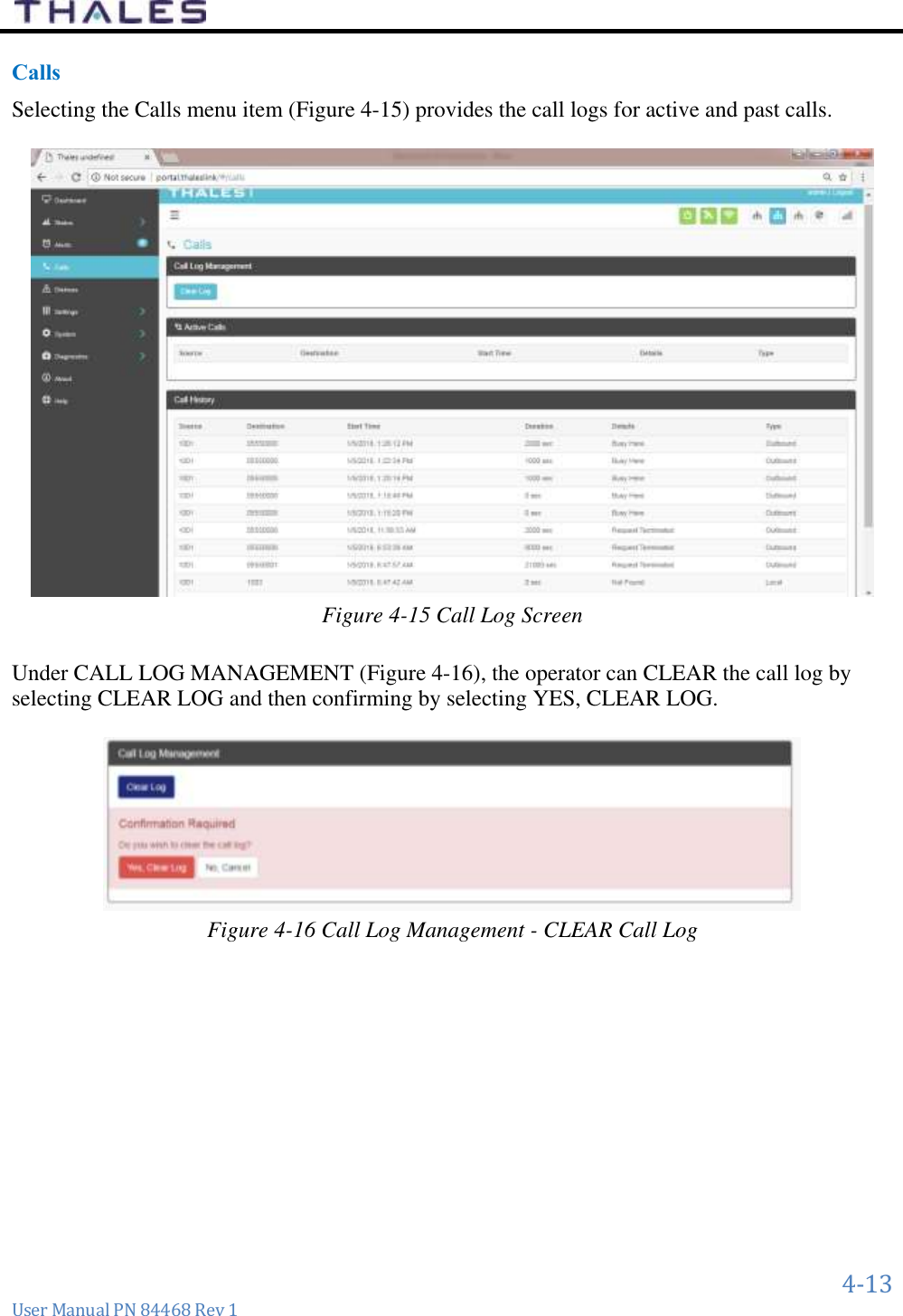
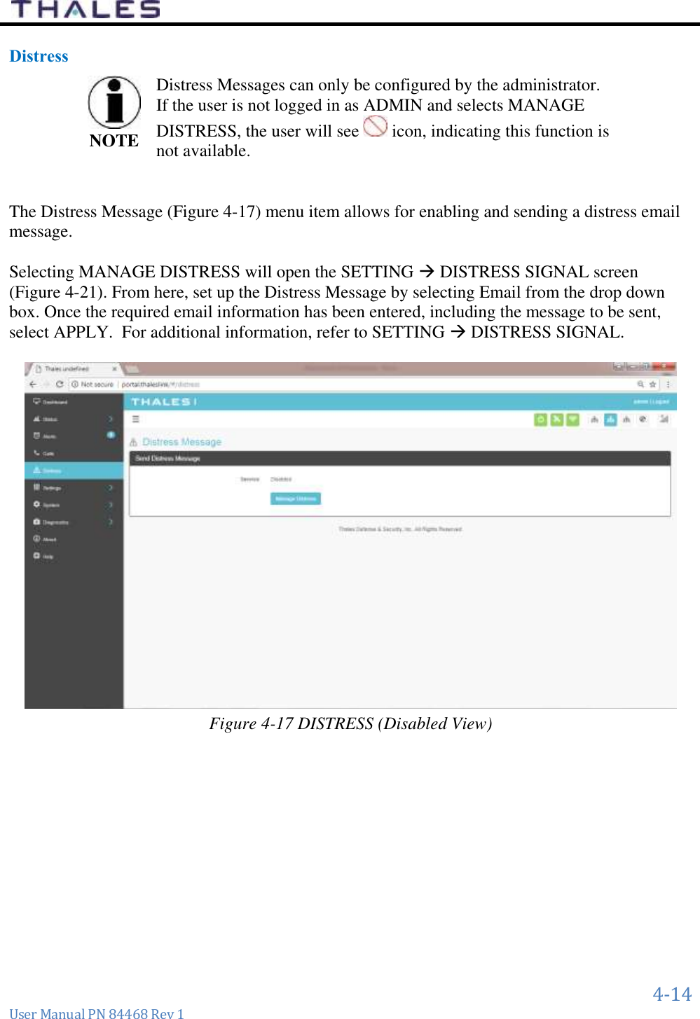
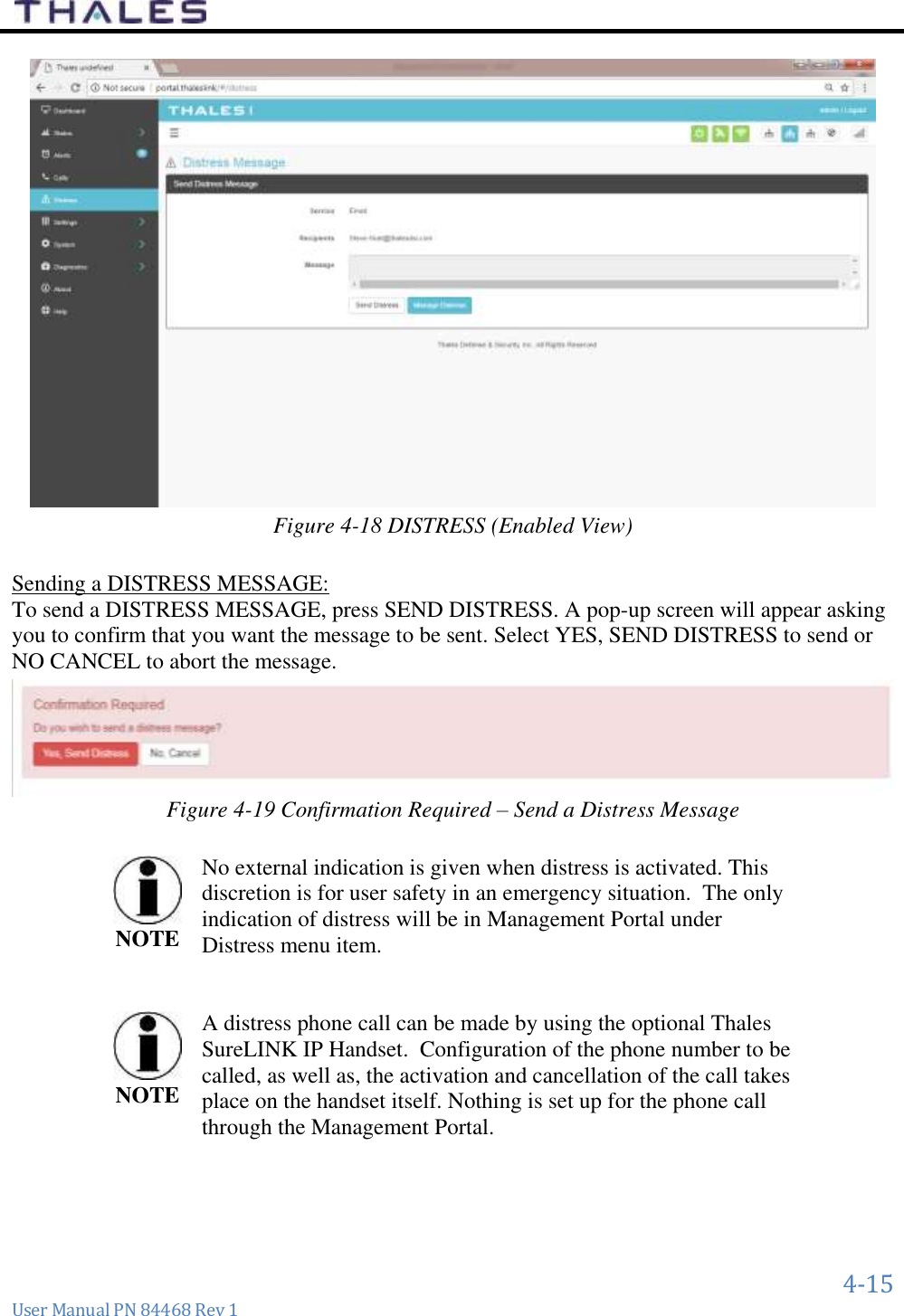
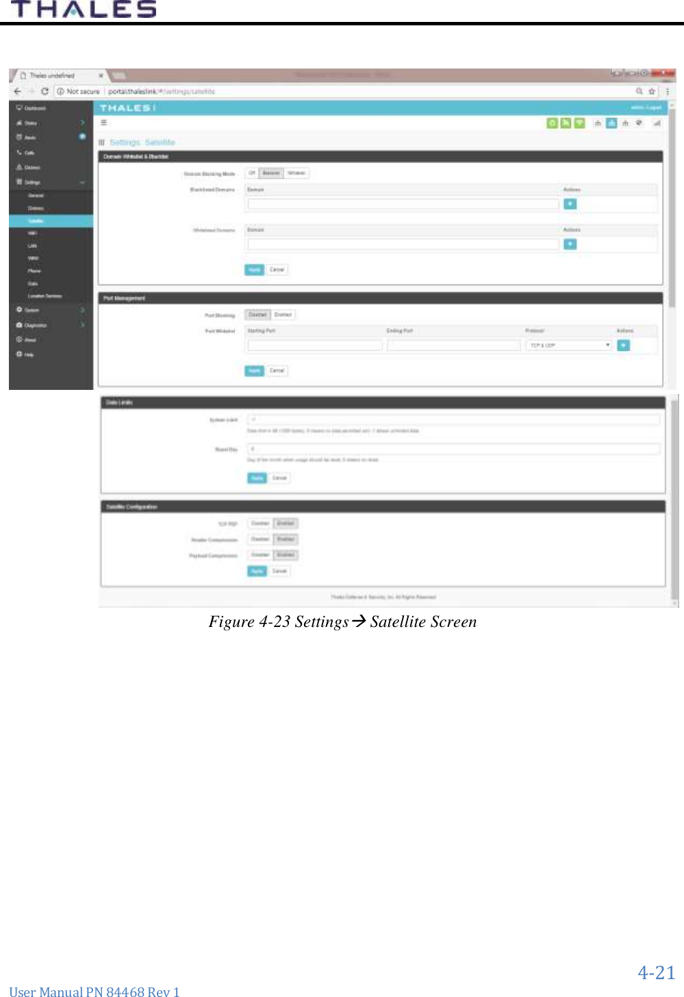
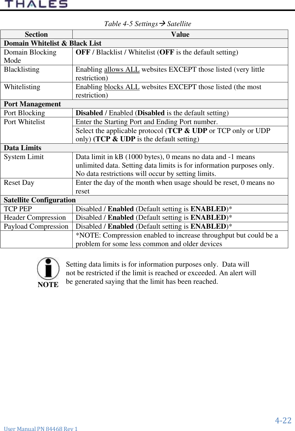
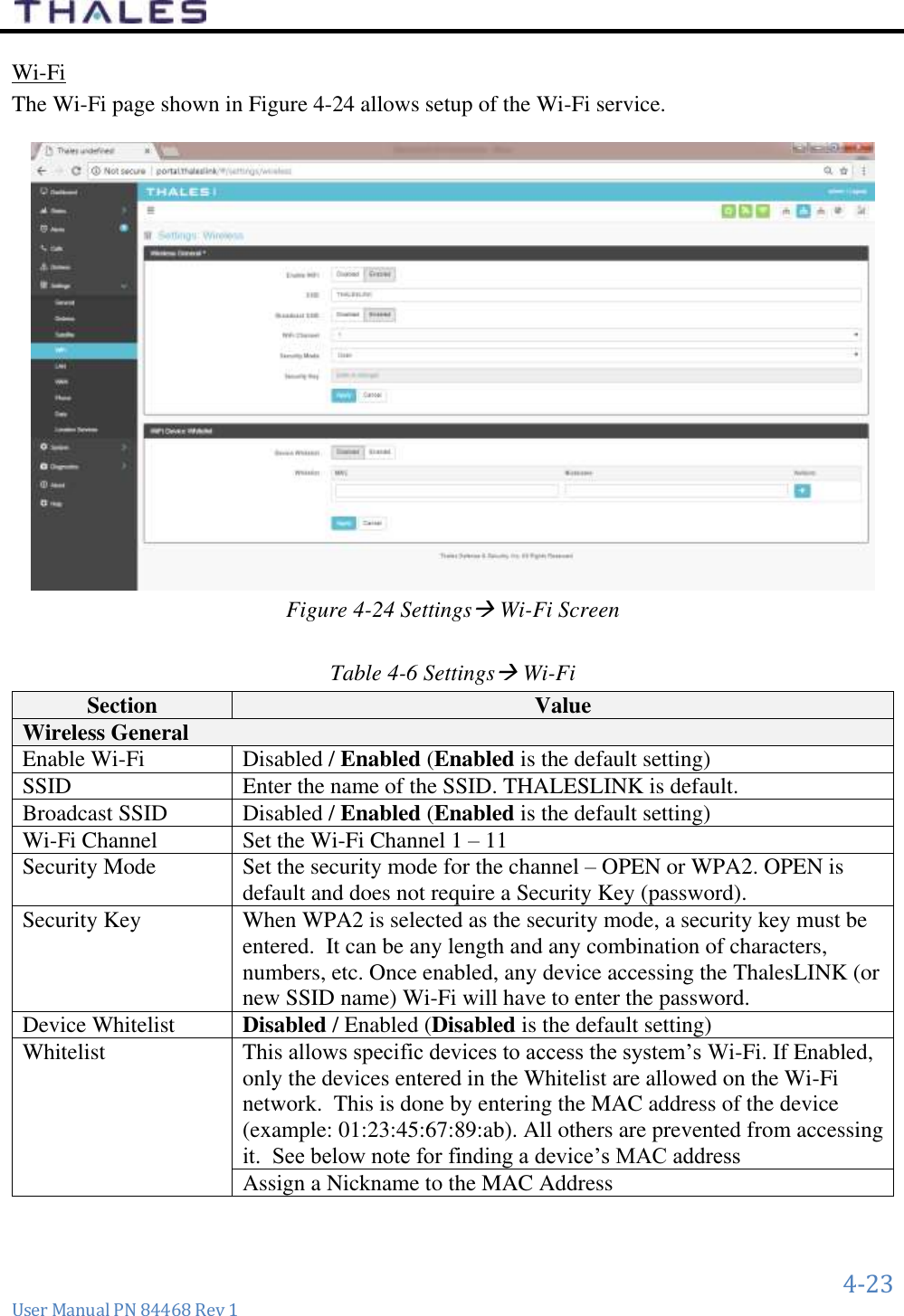
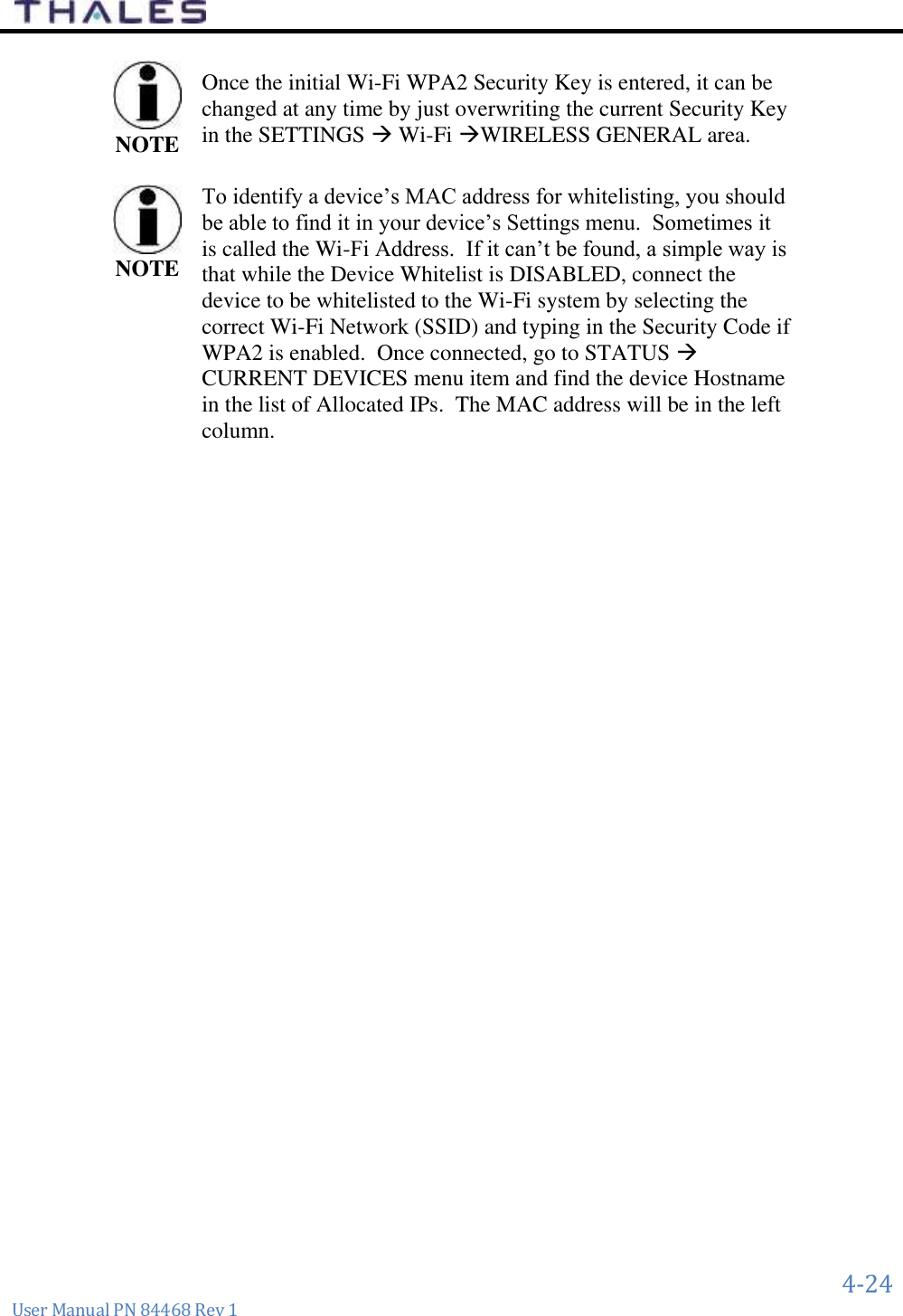
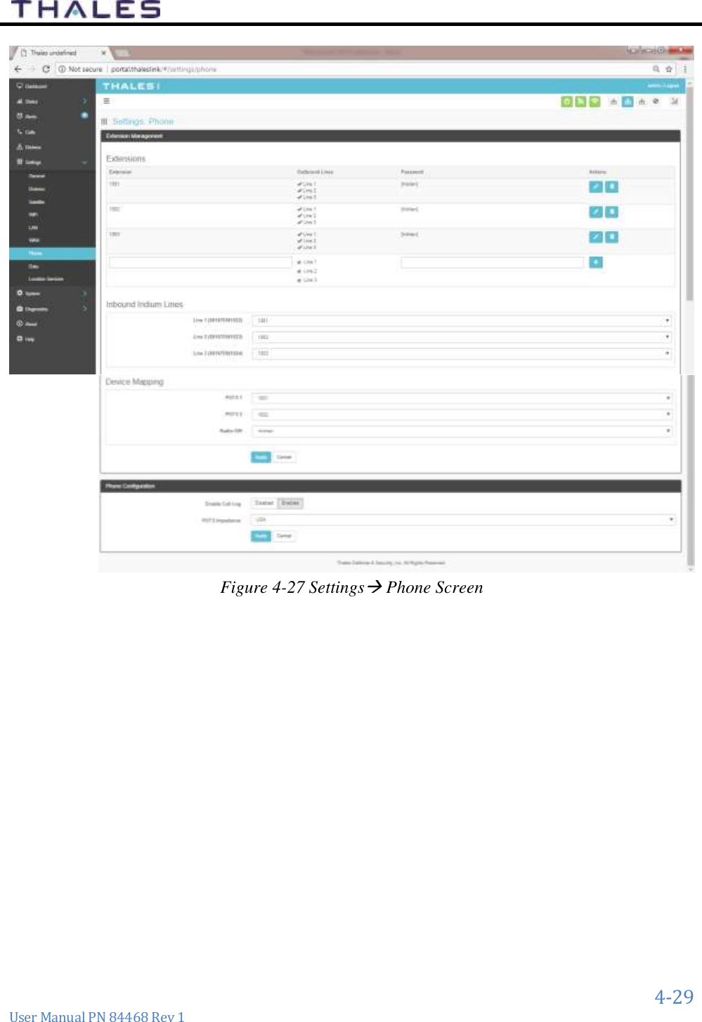
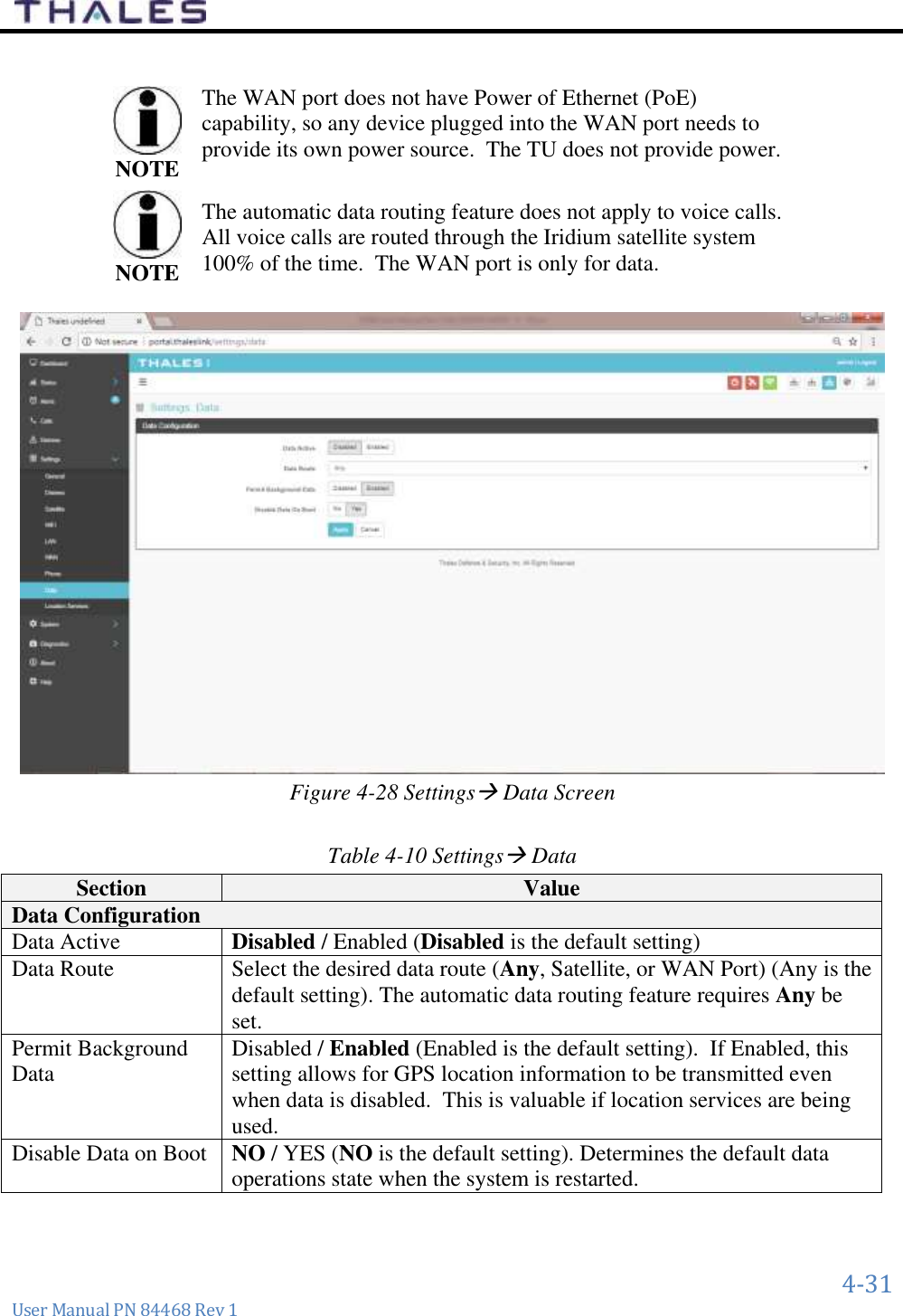
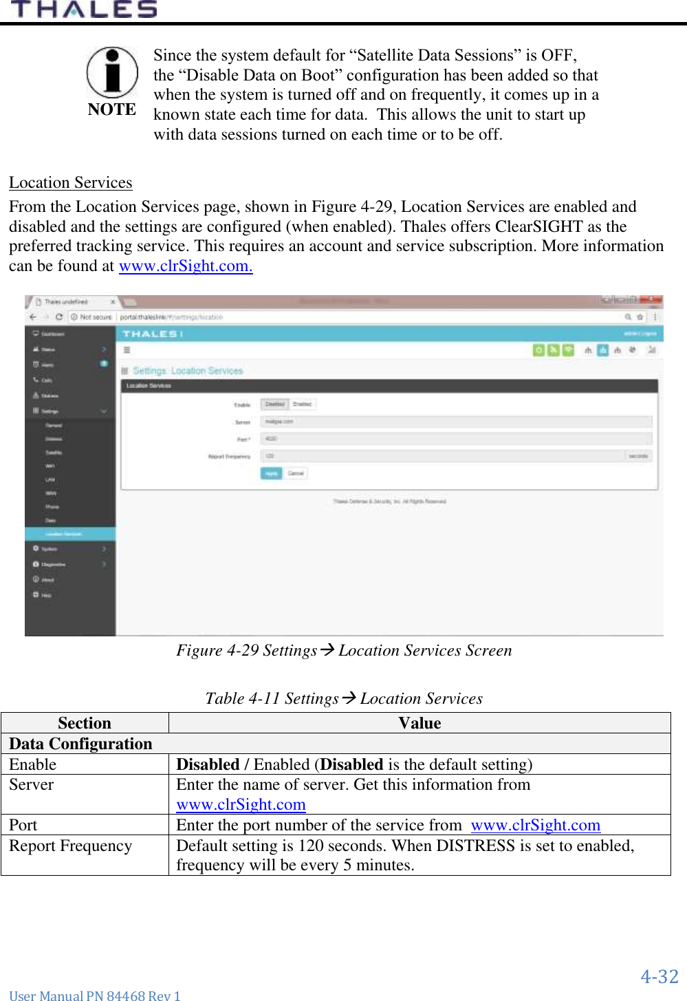
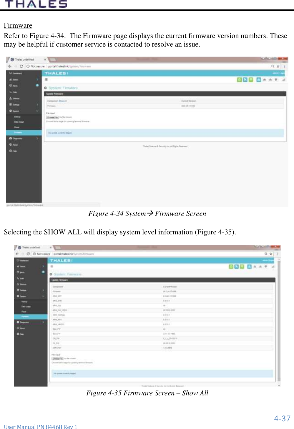
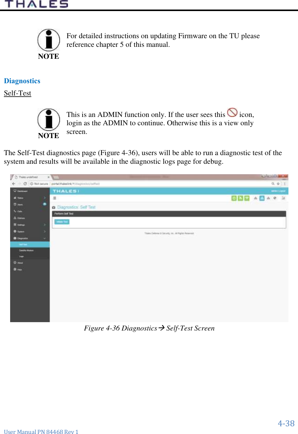
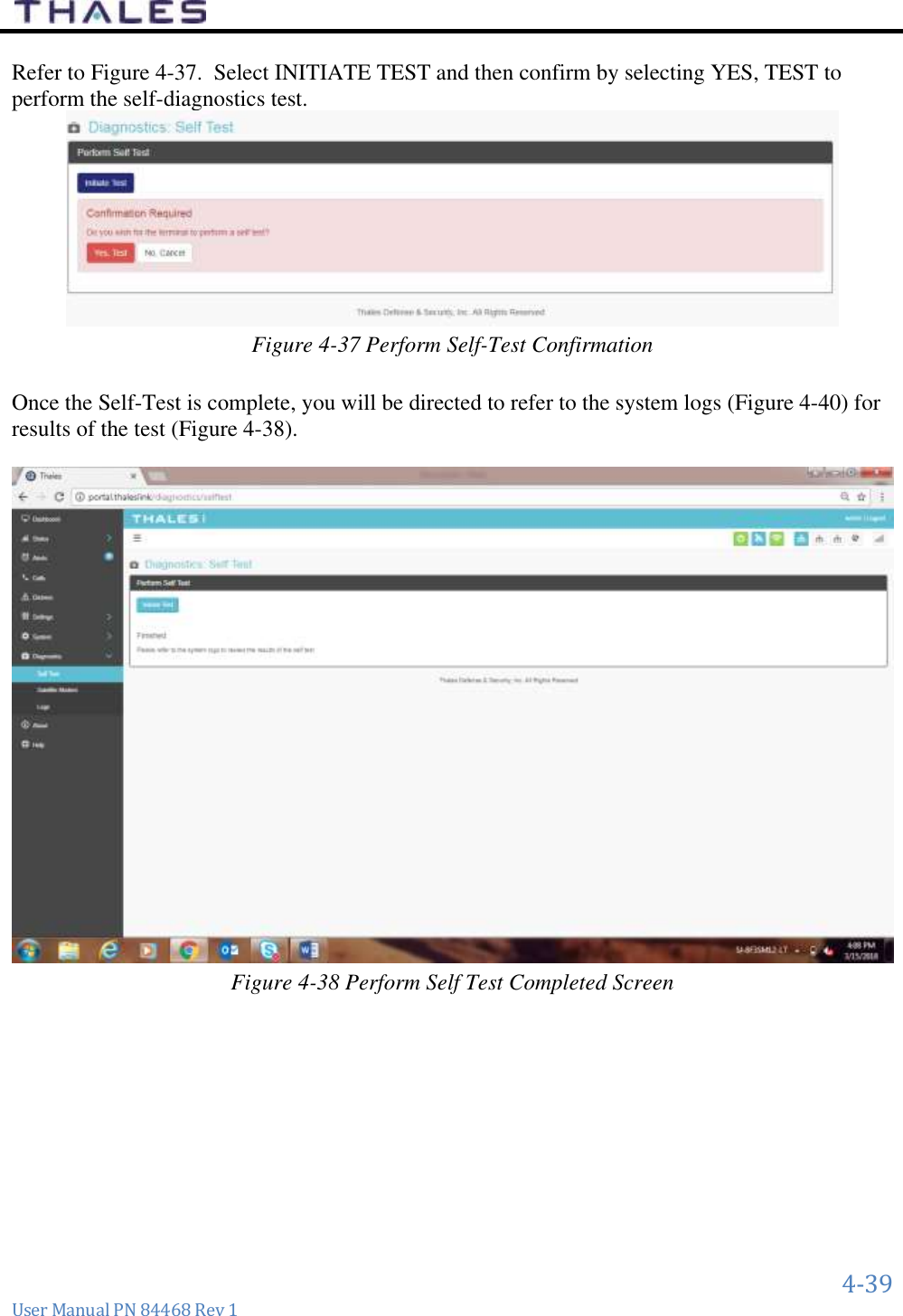
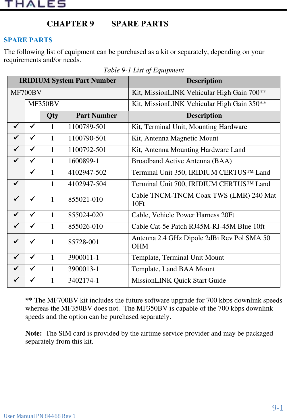
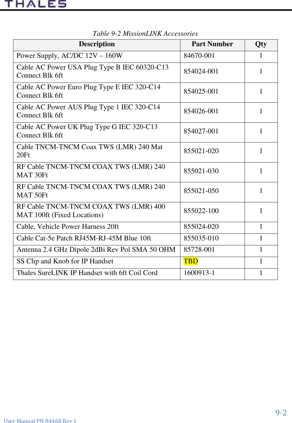
Thales Defense and Security MF350BV Broadband Maritime Certus Satellite Terminal and Antenna User Manual
Thales Defense & Security, Inc. Broadband Maritime Certus Satellite Terminal and Antenna
UserManual.wiki
>
Thales Defense and Security
>
MF350BV User Manual
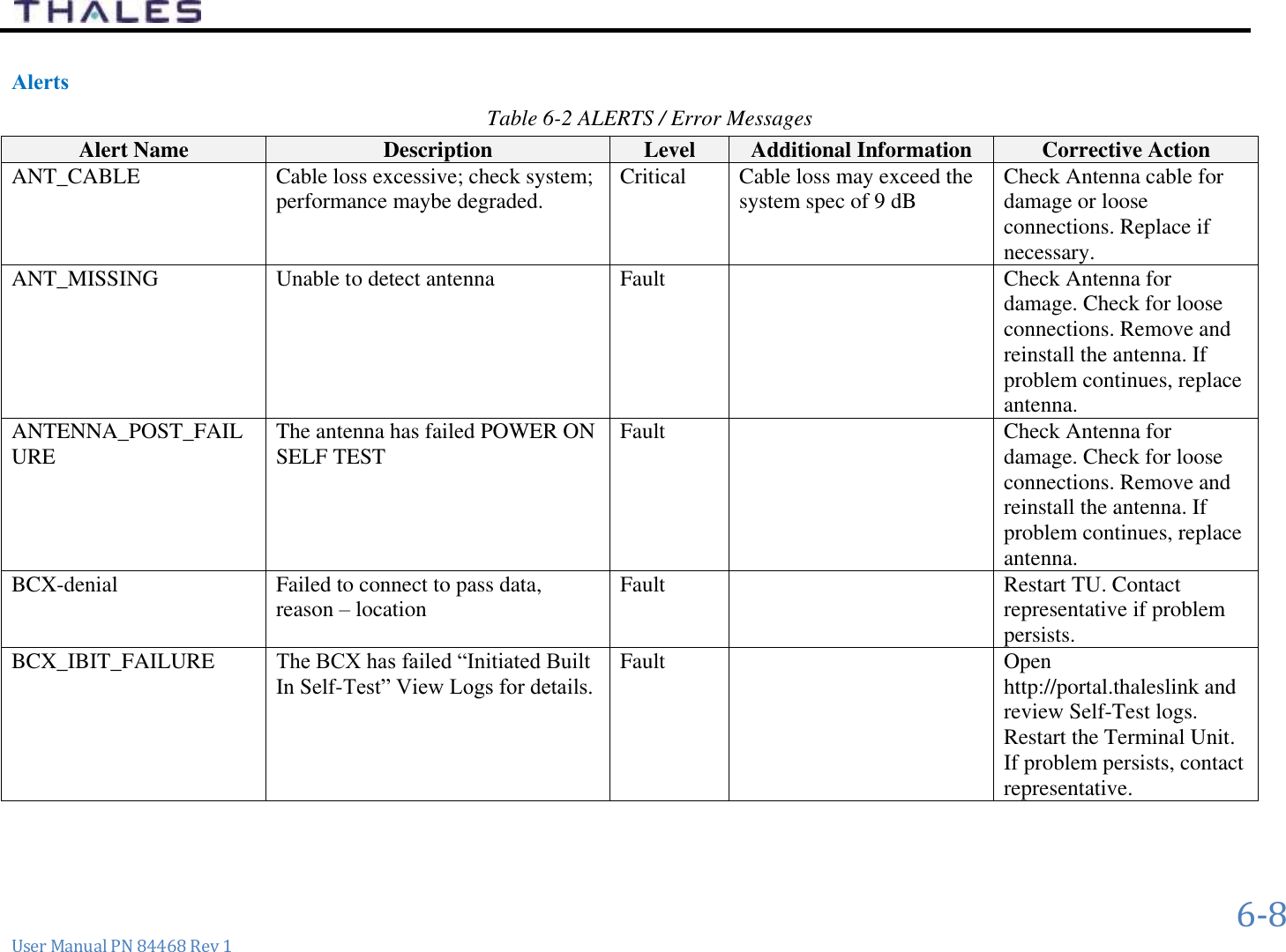
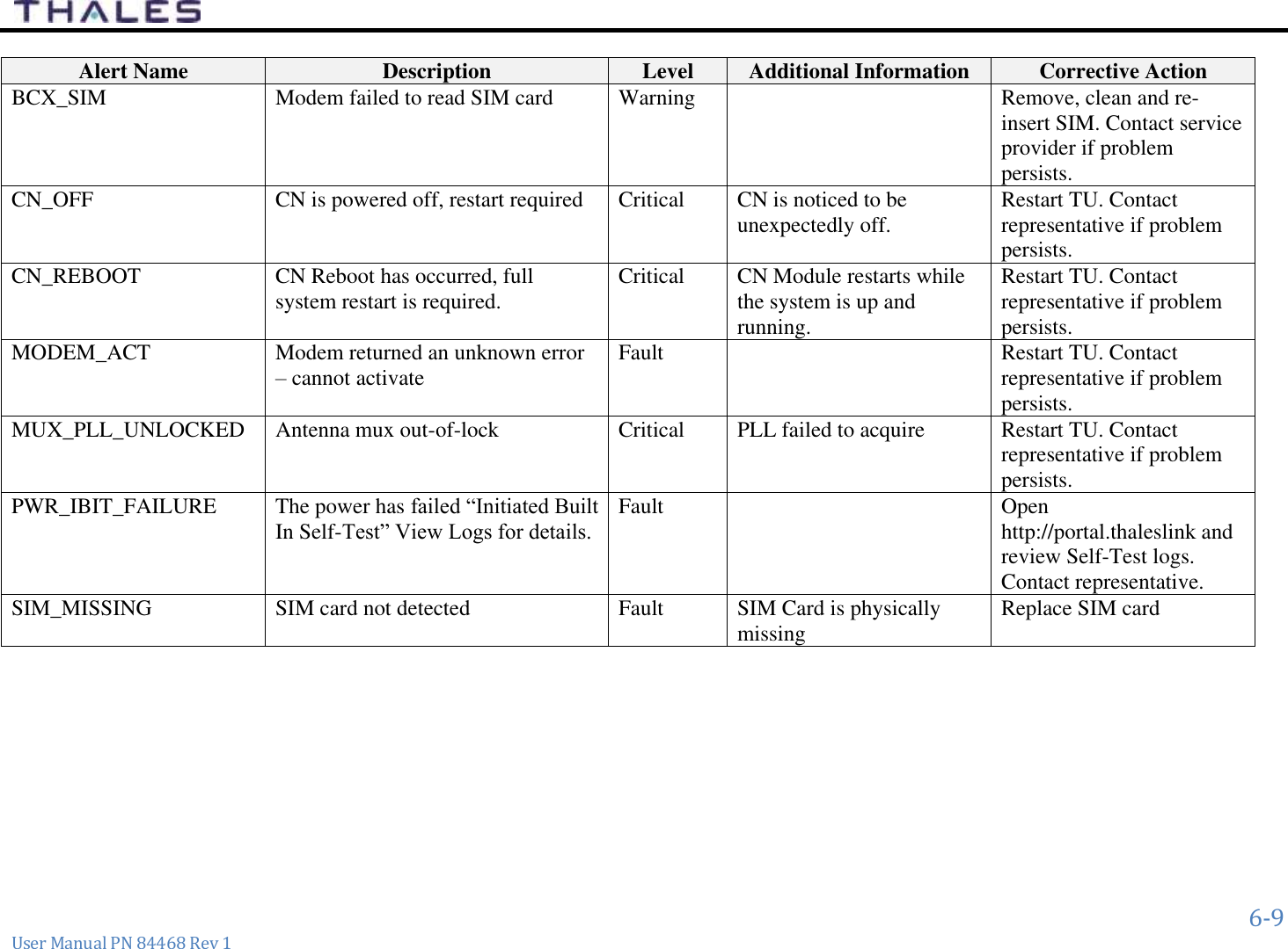
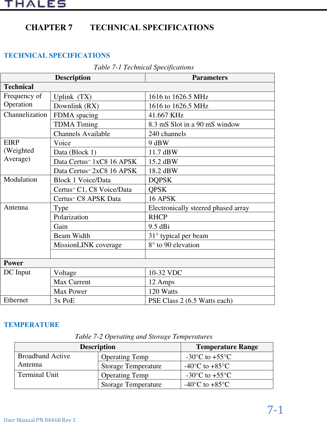
User Manual
Navigation menu
Upload a User Manual
Namespaces
Wiki Guide
HTML
PDF
Info
Views
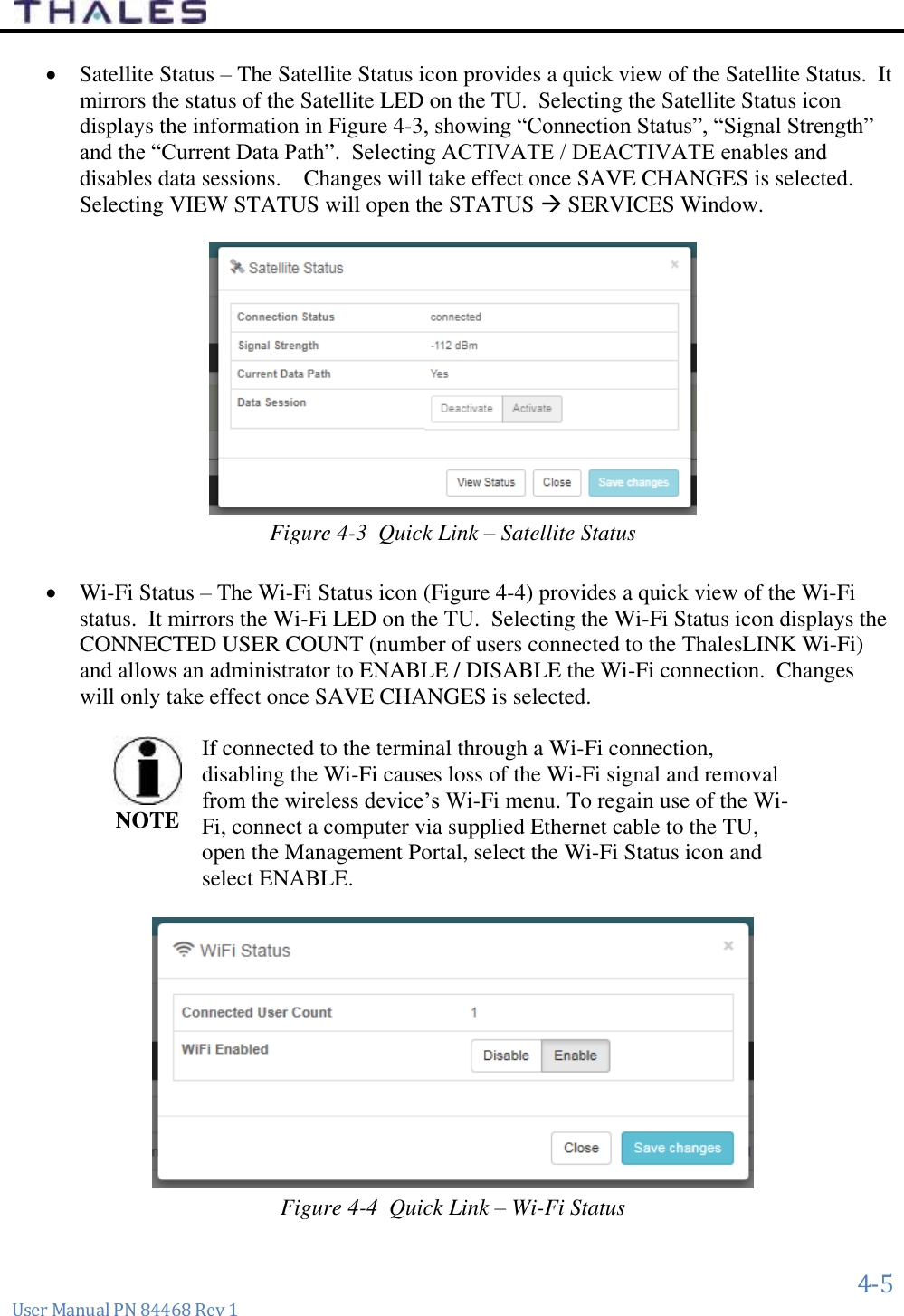
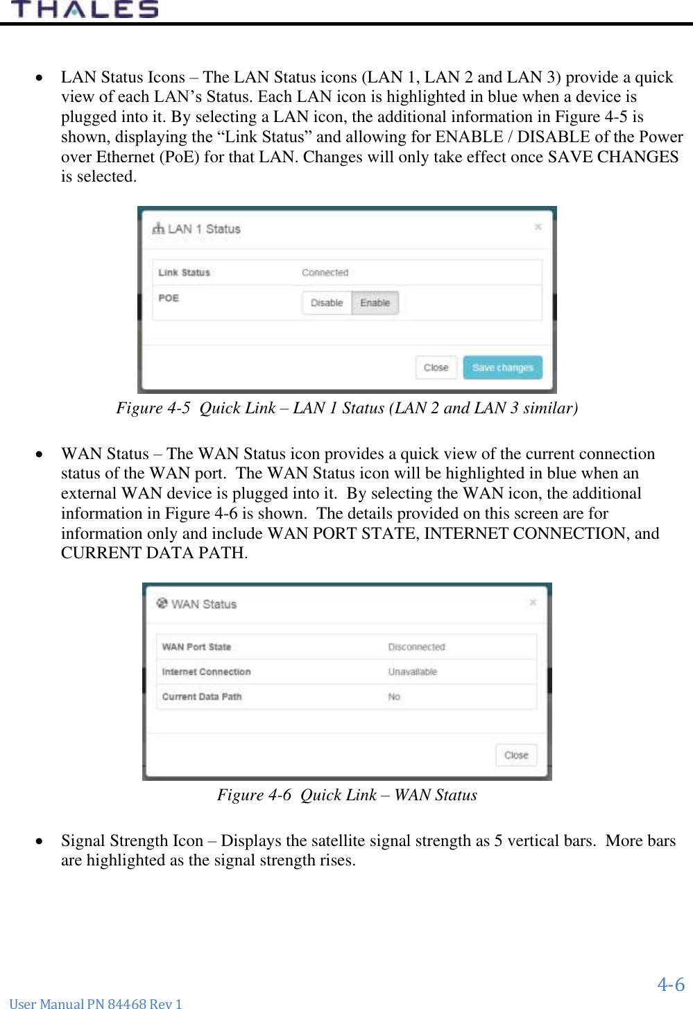
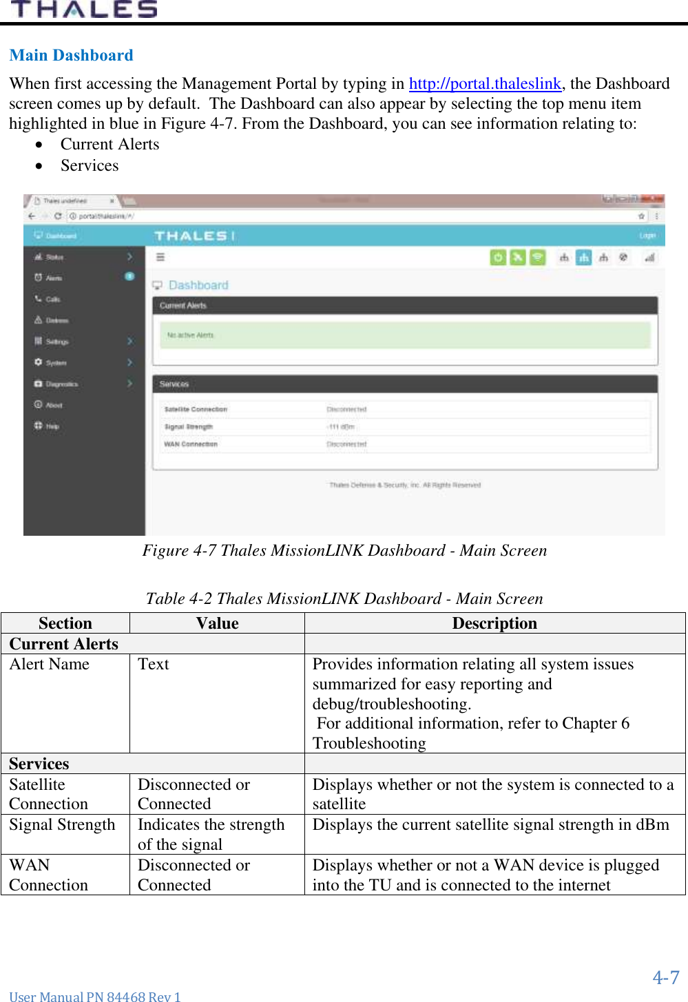
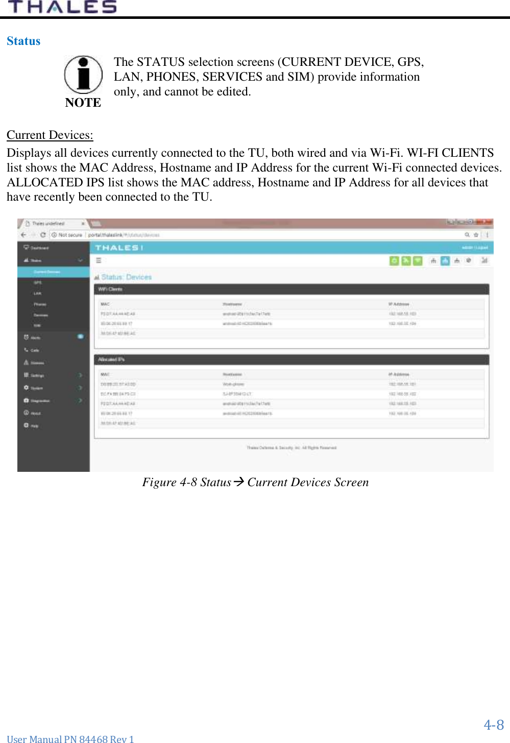
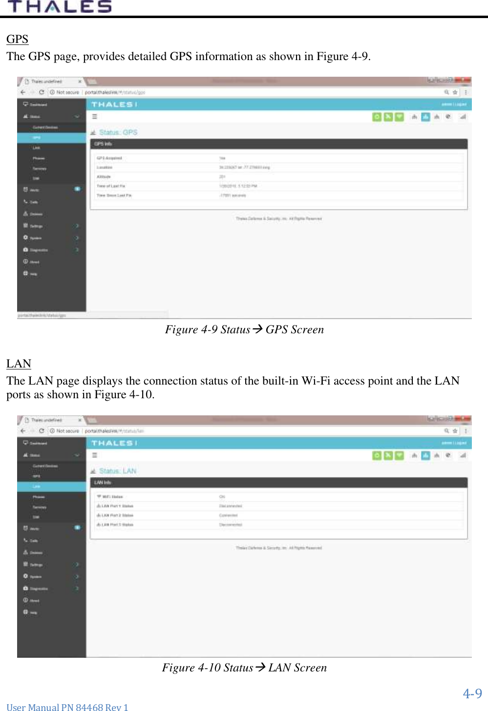
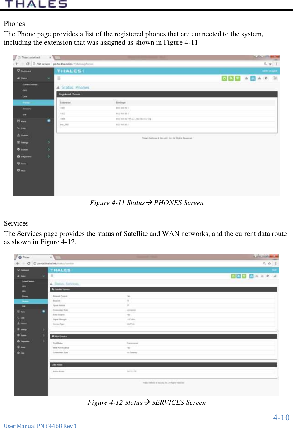
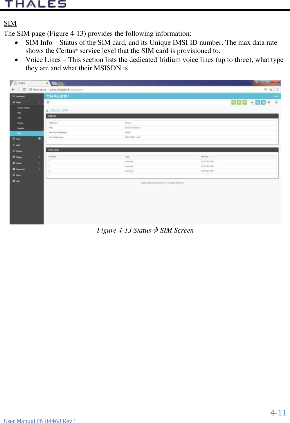
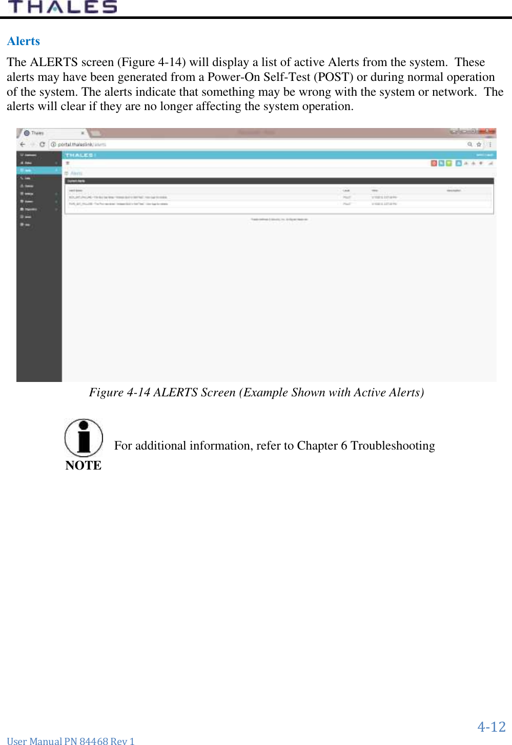
User Manual
Discussion / Help
Navigation