Thales Defense and Security MF350BV Broadband Maritime Certus Satellite Terminal and Antenna User Manual
Thales Defense & Security, Inc. Broadband Maritime Certus Satellite Terminal and Antenna
User Manual

i
User Manual PN 84468 Rev 1
Thales MissionLINK™
User Guide
This document contains technology controlled for export by the U.S. Department of Commerce in
accordance with Export Administration Regulations. Diversion contrary to U.S. law prohibited.
MARCH 2018
JUNE 2017
JUNE 2017
JUNE 2017

ii
User Manual PN 84468 Rev 1
RECORD OF CHANGES
Rev
Date
Description of Change
Author
Rev 1
Mar 2018
Initial Release
SJacques
WARNING – INFORMATION SUBJECT TO EXPORT CONTROL RESTRICTIONS
This document contains technology controlled for export by the U.S. Department of
Commerce in accordance with Export Administration Regulations (EAR). Diversion contrary
to U.S. law prohibited. Include this notice with any reproduced portion of this document.

iii
User Manual PN 84468 Rev 1
Export Compliance:
This product is controlled by the export laws and regulations of the United States of America. The U.S. Government may restrict the
export or re-export of this product to certain individuals and/or destinations. For further information, contact the U.S. Department of
Commerce, Bureau of Industry and Security.
This product User shall comply with all applicable laws related to export and import of this product in any jurisdiction and/or
government authority. User shall be responsible for complying with any and all export and import restrictions, laws and regulations in
any country User is conducting business.
Disclaimer:
This manual contains information that is current as of the date shown on the front cover. Every effort has been made to ensure the
correctness and completeness of the material in this document. The information in this document is subject to change without notice.
Thales®, Thales MissionLINK™, and any other Thales trademark or Thales service mark referred to or displayed in this document are
trademarks or registered trademarks of Thales.
Legal Notices
This product is subject to a Limited Warranty, Limitations, Exclusions, and Terms and Conditions, which can be found on line at
www.thalesdsi.com.
Prior to Installing this product, read and understand this Installation Guide and the User Manual, including the safety warnings and
information. Failure to do so could result in serious injury or death.
Intellectual Property
User acknowledges that the Products
involve
valuable patent, copyright, trademark, trade secret and other proprietary rights
of
Thales and others. No title to or ownership of any proprietary rights related to any Product is transferred to User or any Customer
pursuant to the use of this product. The purchase of any Thales products shall not be deemed to grant either directly or by implication
or otherwise, any license under copyrights, patents, or patent applications of Thales or any third party software providers, except for
the normal, nonexclusive, royalty free license to use that arises by operation of law in the sale of a product.
C on t en t Co p yri ght
User is exclusively responsible for the use of this product, including proper use of third party copyrighted materials. If the User violates
these terms, the User agrees to defend, indemnify and hold Thales harmless with respect to any claims or actions by third parties
related to the improper use of copyrighted material and to pay all costs, damages, fines and other amounts incurred by Thales, or on
its behalf, in the defense of any such claims or actions.
I nd e mni ty
User agrees to defend, indemnify and hold Thales harmless with respect to any claims or actions by any governmental entities or other
third parties related to any violation of law with use of the Product or Accessories, misuse of the Product or Accessories under these
Terms and Conditions, or any other violation of these Terms and Conditions and further agrees to pay all costs, damages, fines and
other amounts incurred by Thales, or on Thales’s behalf, in the defense of any such claims or actions.
S OF T WAR E L I CEN S E
The following terms govern User’s access and use of the Thales-supplied software (“Software”) contained on the Product or
Accessories.
License. Conditioned upon compliance with these Terms and Conditions, Thales grants to USER a nonexclusive and nontransferable
license to use for USER’s internal purposes the Software and the Documentation. “Documentation” means any written information
pertaining to the Software and made available by Thales with the Software in any manner. USER shall use the Software solely as
embedded for operation of this product.
No other licenses are granted by implication, estoppel or otherwise.
Tha l es Pro d uct Wa r ra n ty C lai m P r oce s s
Please see the Thales website at www.thalesdsi.com.
User Documentation:
Thales Defense & Security, Inc. continually evaluates its user documentation for accuracy and completeness. Any suggestions you may
have for changes or additions should be sent to THALES_ILS@thalesdsi.com Subject Line: Thales MissionLINK™ User’s Guide (PN
84468).

iv
User Manual PN 84468 Rev 1
Table of Contents
INTRODUCTION ........................................................... 1-1
CHAPTER 1
INTRODUCTION .......................................................................................................................................................... 1-1
ABOUT THIS MANUAL ................................................................................................................................................. 1-1
THE IRIDIUM SATELLITE NETWORK ................................................................................................................................ 1-1
SYSTEM OVERVIEW .................................................... 2-1 CHAPTER 2
DESCRIPTION ............................................................................................................................................................ 2-1
Terminal Unit (TU) ............................................................................................................................................ 2-4
Broadband Active Antenna (BAA) .................................................................................................................... 2-7
GETTING STARTED ..................................................... 3-1 CHAPTER 3
GETTING STARTED .................................................................................................................................................... 3-1
THALES MANAGEMENT PORTAL ............................ 4-1 CHAPTER 4
GETTING TO KNOW THE THALES MANAGEMENT PORTAL ................................................................................................... 4-1
Menu Components ........................................................................................................................................... 4-3
Main Dashboard ............................................................................................................................................... 4-7
Status ............................................................................................................................................................... 4-8
Alerts .............................................................................................................................................................. 4-12
Calls ................................................................................................................................................................ 4-13
Distress ........................................................................................................................................................... 4-14
Settings ........................................................................................................................................................... 4-16
System ............................................................................................................................................................ 4-33
Diagnostics ..................................................................................................................................................... 4-38
About .............................................................................................................................................................. 4-43
Help ................................................................................................................................................................ 4-44
FIRMWARE UPGRADE ................................................ 5-1 CHAPTER 5
INSTALLING THE FIRMWARE ON MISSIONLINK ............................................................................................................ 5-2
TROUBLESHOOTING ................................................... 6-1 CHAPTER 6
TROUBLESHOOTING .............................................................................................................................................. 6-1
System Resets ................................................................................................................................................... 6-5
Alerts ................................................................................................................................................................ 6-8
TECHNICAL SPECIFICATIONS .................................. 7-1 CHAPTER 7
TECHNICAL SPECIFICATIONS ......................................................................................................................................... 7-1
TEMPERATURE .......................................................................................................................................................... 7-1
PHYSICAL CHARACTERISTICS ......................................................................................................................................... 7-2
CONNECTOR DETAILS: ................................................................................................................................................ 7-2
General Purpose Inputs / Outputs (GPIO) ........................................................................................................ 7-2
TU 12V Connection Detail ................................................................................................................................ 7-5
TU 10-32VDC Connection Detail ....................................................................................................................... 7-5

v
User Manual PN 84468 Rev 1
ACRONYMS / GLOSSARY ............................................ 8-1 CHAPTER 8
ACRONYMS / GLOSSARY .............................................................................................................................................. 8-1
SPARE PARTS ................................................................ 9-1
CHAPTER 9
SPARE PARTS ......................................................................................................................................................... 9-1
List of Figures
FIGURE 1-1 EARTH SHOWING IRIDIUM SATELLITES IN SIX DEFINED ORBITAL PLANES. ............................................... 1-2
FIGURE 1-2 TYPICAL IRIDIUM NETWORK FLOW OF A VOICE OR DATA CALL. ............................................................ 1-2
FIGURE 2-1 THREE CHANNEL VOICE CALLING OVERVIEW ........................................................................................ 2-1
FIGURE 2-2 LOCAL COMMUNICATIONS VIA PBX FUNCTIONALITY ............................................................................. 2-2
FIGURE 2-3 MISSIONLINK SYSTEM WITH CONNECTED HARDWARE .......................................................................... 2-3
FIGURE 2-4 TERMINAL UNIT (TU) .............................................................................................................................. 2-4
FIGURE 2-5 TERMINAL UNIT (TU) LEDS ................................................................................................................... 2-5
FIGURE 2-6 TERMINAL UNIT (TU) FRONT PANEL DETAIL .......................................................................................... 2-6
FIGURE 2-7 TERMINAL UNIT (TU) BACK PANEL DETAIL ........................................................................................... 2-7
FIGURE 2-8 BROADBAND ACTIVE ANTENNA (BAA) UNIT ......................................................................................... 2-7
FIGURE 3-1 TERMINAL UNIT (TU) FRONT PANEL DETAIL .......................................................................................... 3-1
FIGURE 3-2 MISSIONLINK IMEI AND IMSI FROM MOBILE DEVICE .......................................................................... 3-2
FIGURE 3-3 SIM CARD WITH COVER OPENED ............................................................................................................ 3-3
FIGURE 3-4 INSTALLING SIM CARD AND ENGAGING THE LOCK ................................................................................ 3-3
FIGURE 3-5 SECURE THE SIM CARD COVER............................................................................................................... 3-4
FIGURE 3-6 SYSTEM, SATELLITE AND WI-FI STATUS LED’S ...................................................................................... 3-4
FIGURE 3-7 MISSIONLINK USER INTERFACE LOGIN .................................................................................................. 3-6
FIGURE 4-1 QUICK LINK ICONS ................................................................................................................................. 4-3
FIGURE 4-2 QUICK LINK – SYSTEM STATUS .............................................................................................................. 4-4
FIGURE 4-3 QUICK LINK – SATELLITE STATUS .......................................................................................................... 4-5
FIGURE 4-4 QUICK LINK – WI-FI STATUS .................................................................................................................. 4-5
FIGURE 4-5 QUICK LINK – LAN 1 STATUS (LAN 2 AND LAN 3 SIMILAR)................................................................. 4-6
FIGURE 4-6 QUICK LINK – WAN STATUS .................................................................................................................. 4-6
FIGURE 4-7 THALES MISSIONLINK DASHBOARD - MAIN SCREEN ............................................................................. 4-7
FIGURE 4-8 STATUS CURRENT DEVICES SCREEN .................................................................................................... 4-8
FIGURE 4-9 STATUS GPS SCREEN .......................................................................................................................... 4-9
FIGURE 4-10 STATUS LAN SCREEN ....................................................................................................................... 4-9
FIGURE 4-11 STATUS PHONES SCREEN .............................................................................................................. 4-10
FIGURE 4-12 STATUS SERVICES SCREEN ........................................................................................................... 4-10
FIGURE 4-13 STATUS SIM SCREEN ....................................................................................................................... 4-11
FIGURE 4-14 ALERTS SCREEN (EXAMPLE SHOWN WITH ACTIVE ALERTS) ............................................................. 4-12
FIGURE 4-15 CALL LOG SCREEN .............................................................................................................................. 4-13
FIGURE 4-16 CALL LOG MANAGEMENT - CLEAR CALL LOG .................................................................................. 4-13
FIGURE 4-17 DISTRESS (DISABLED VIEW)............................................................................................................. 4-14
FIGURE 4-18 DISTRESS (ENABLED VIEW) ............................................................................................................. 4-15
FIGURE 4-19 CONFIRMATION REQUIRED – SEND A DISTRESS MESSAGE .................................................................. 4-15
FIGURE 4-20 SETTINGS GENERAL SCREEN .......................................................................................................... 4-17
FIGURE 4-21 SETTINGS DISTRESS (INITIAL SCREEN) ........................................................................................... 4-18
FIGURE 4-22 SETTINGS DISTRESS ........................................................................................................................ 4-19
FIGURE 4-23 SETTINGS SATELLITE SCREEN ......................................................................................................... 4-21
FIGURE 4-24 SETTINGS WI-FI SCREEN ................................................................................................................. 4-23
FIGURE 4-25 SETTINGS LAN SCREEN................................................................................................................... 4-25
FIGURE 4-26 SETTINGS WAN SCREEN ................................................................................................................. 4-27

vi
User Manual PN 84468 Rev 1
FIGURE 4-27 SETTINGS PHONE SCREEN ................................................................................................................ 4-29
FIGURE 4-28 SETTINGS DATA SCREEN ................................................................................................................. 4-31
FIGURE 4-29 SETTINGS LOCATION SERVICES SCREEN .......................................................................................... 4-32
FIGURE 4-30 SYSTEM BACKUP SCREEN ............................................................................................................... 4-33
FIGURE 4-31 SYSTEM DATA USAGE SCREEN ........................................................................................................ 4-35
FIGURE 4-32 RESET DATA USAGE SCREEN .............................................................................................................. 4-35
FIGURE 4-33 SYSTEM RESET .............................................................................................................................. 4-36
FIGURE 4-34 SYSTEM FIRMWARE SCREEN ............................................................................................................ 4-37
FIGURE 4-34 FIRMWARE SCREEN – SHOW ALL ........................................................................................................ 4-37
FIGURE 4-36 DIAGNOSTICS SELF-TEST SCREEN ................................................................................................... 4-38
FIGURE 4-37 PERFORM SELF-TEST CONFIRMATION ................................................................................................. 4-39
FIGURE 4-38 PERFORM SELF TEST COMPLETED SCREEN .......................................................................................... 4-39
FIGURE 4-39 DIAGNOSTICS SATELLITE MODEM SCREEN ..................................................................................... 4-41
FIGURE 4-40 DIAGNOSTICS LOGS SCREEN ............................................................................................................ 4-42
FIGURE 4-41 ABOUT SCREEN ................................................................................................................................... 4-43
FIGURE 4-42 HELP SCREEN (EXAMPLE) ................................................................................................................... 4-44
FIGURE 5-1 SYSTEM FIRMWARE ............................................................................................................................. 5-2
FIGURE 5-2 FIRMWARE BEING STAGED ...................................................................................................................... 5-3
FIGURE 5-3 SYSTEM FIRMWARE UPDATE CONFIRM ............................................................................................... 5-3
FIGURE 5-4 FIRMWARE UPDATE IN PROCESS .............................................................................................................. 5-4
FIGURE 5-5 SYSTEM FIRMWARE UPDATE COMPLETED .......................................................................................... 5-5
FIGURE 6-1 LOCATION OF POWER BUTTON ON TERMINAL UNIT (TU) ....................................................................... 6-5
FIGURE 6-2 MANAGEMENT PORTAL - SYSTEM RESET ....................................................................................... 6-5
FIGURE 6-3 RESET BUTTON ................................................................................................................................... 6-6
FIGURE 7-1 RADIO GATEWAY FOR ADVANCED LAND MOBILE SERVICES .................................................................. 7-3
FIGURE 7-2 GPIO CONNECTOR PIN DETAIL ............................................................................................................... 7-4
FIGURE 7-3 12V INPUT AND MATING CONNECTOR DETAIL ....................................................................................... 7-5
FIGURE 7-4 10-32 VDC AND MATING CONNECTOR DETAIL ...................................................................................... 7-5
List of Tables
TABLE 2-1 TERMINAL UNIT LED STATUS .................................................................................................................. 2-5
TABLE 3-1 TYPICAL VOIP PHONE CONFIGURATION ................................................................................................... 3-1
TABLE 3-2 TERMINAL UNIT LED STATUS .................................................................................................................. 3-5
TABLE 4-1 QUICK LINK ICONS ................................................................................................................................... 4-4
TABLE 4-2 THALES MISSIONLINK DASHBOARD - MAIN SCREEN .............................................................................. 4-7
TABLE 4-3 SETTINGS GENERAL SETTINGS ........................................................................................................... 4-18
TABLE 4-4 SETTINGS DISTRESS ........................................................................................................................... 4-19
TABLE 4-5 SETTINGS SATELLITE .......................................................................................................................... 4-22
TABLE 4-6 SETTINGS WI-FI .................................................................................................................................. 4-23
TABLE 4-7 SETTINGS LAN ................................................................................................................................... 4-25
TABLE 4-8 SETTINGS WAN .................................................................................................................................. 4-27
TABLE 4-9 SETTINGS PHONE ................................................................................................................................ 4-30
TABLE 4-10 SETTINGS DATA ................................................................................................................................ 4-31
TABLE 4-11 SETTINGS LOCATION SERVICES ........................................................................................................ 4-32
TABLE 6-1 TROUBLESHOOTING .................................................................................................................................. 6-1
TABLE 6-2 ALERTS / ERROR MESSAGES................................................................................................................... 6-8
TABLE 7-1 TECHNICAL SPECIFICATIONS .................................................................................................................... 7-1
TABLE 7-2 OPERATING AND STORAGE TEMPERATURES ............................................................................................. 7-1
TABLE 7-3 PHYSICAL CHARACTERISTICS ................................................................................................................... 7-2
TABLE 7-4 GPIO CONNECTOR PIN DEFINITION .......................................................................................................... 7-4
TABLE 8-1 LIST OF ACRONYMS .................................................................................................................................. 8-1
TABLE 8-2 LIST OF DEFINITIONS ................................................................................................................................ 8-2
TABLE 9-1 LIST OF EQUIPMENT .................................................................................................................................. 9-1
TABLE 9-2 MISSIONLINK ACCESSORIES .................................................................................................................... 9-2

vii
User Manual PN 84468 Rev 1
SAFETY
The Thales MissionLINK™ system should only be installed by a qualified installers of land
electronic systems. Improper installation could lead to system failure or could result in injury.
The following are general safety precautions and warnings that all personnel must read and
understand prior to installation, operation and maintenance of the Thales MissionLINK™
system. Each chapter may have other specific warnings and cautions.
WARNING
USHOCK HAZARD
The MissionLINK™ system is a sealed system and is not meant to be
opened for repair in the field by operators or technicians. Covers must
remain in place at all times on the Terminal Unit and Broadband Active
Antenna to maintain the warranty terms. Make sure the system is
correctly grounded and power is off when installing, configuring and
connecting components.
WARNING
DO NOT OPERATE IN AN EXPLOSIVE ATMOSPHERE
This equipment is not designed to be operated in explosive
environments or in the presence of combustible fumes. Operating this or
any electrical equipment in such an environment represents an extreme
safety hazard.
viii
User Manual PN 84468 Rev 1
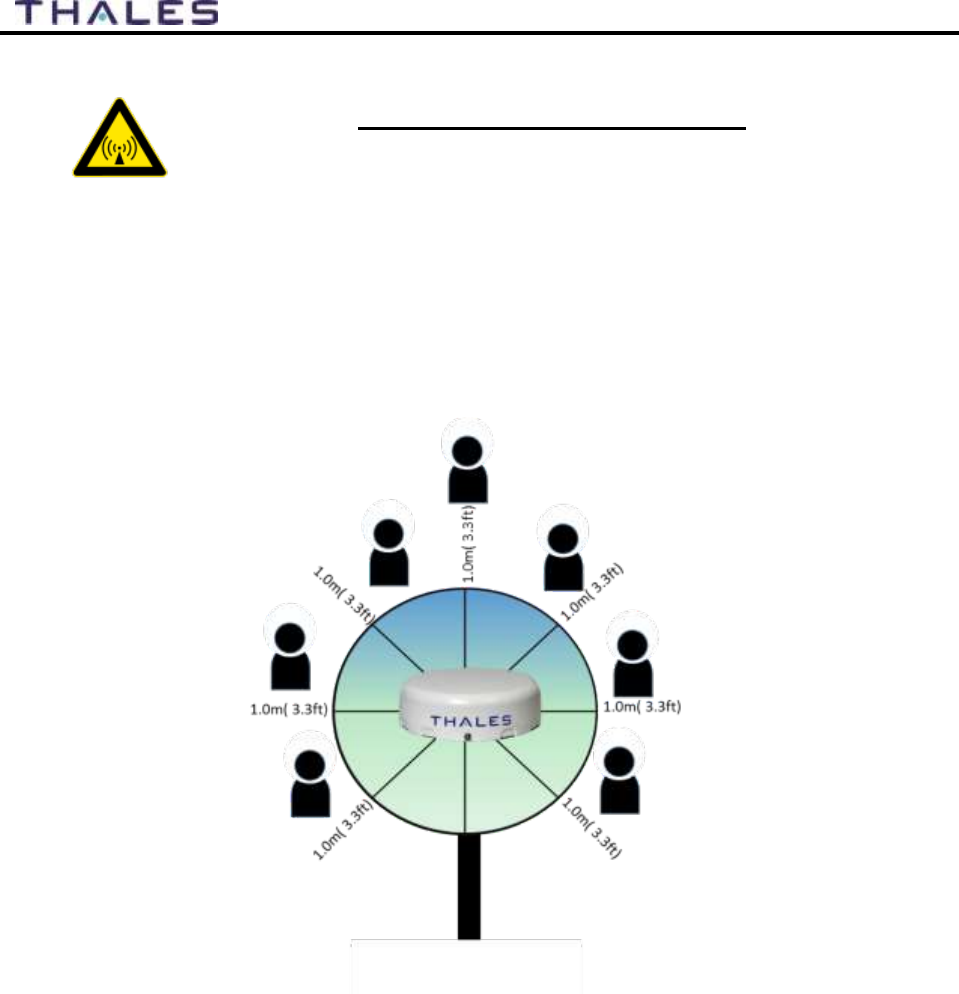
WARNING
ANTENNA RADIATION HAZARDS
To comply with FCC Radio Frequency radiation exposure limits, the
antenna must be installed at a minimum safe distance as shown below.
During operation, the antenna radiates high power at microwave
frequencies that can be harmful to individuals. While the unit is
operating, personnel should maintain a minimum safe distance of 1.0
meters (3.3 ft.) from the antenna. The antenna should be mounted in an
area that prevent the possibility of close exposure to the antenna’s
radiation.

ix
User Manual PN 84468 Rev 1
FCC INFORMATION
Changes or modifications not expressly approved by the manufacturer could void the user’s
authority to operate the equipment.
Note:
This equipment has been tested and found to comply with the limits for a Class B digital device,
pursuant to part 15 of the FCC Rules. These limits are designed to provide reasonable protection
against harmful interference in a residential installation. This equipment generates, uses and can
radiate radio frequency energy and, if not installed and used in accordance with the instructions,
may cause harmful interference to radio communications. However, there is no guarantee that
interference will not occur in a particular installation. If this equipment does cause harmful
interference to radio or television reception, which can be determined by turning the equipment
off and on, the user is encouraged to try to correct the interference by one or more of the
following measures:
Reorient or relocate the receiving antenna.
Increase the separation between the equipment and receiver.
Connect the equipment into an outlet on a circuit different from that to which the receiver
is connected.
Consult the dealer or an experienced radio/TV technician for help.

1-1
User Manual PN 84468 Rev 1
INTRODUCTION CHAPTER 1
INTRODUCTION
Thank you for your recent purchase of a Thales MissionLINK™ product. Powered by the
Iridium global satellite network it’s the only system with truly pole-to-pole coverage for voice
and data communications. This USER MANUAL will cover a basic overview and advanced
options of the Thales MissionLINK™ system.
Additional information can be found in the following documents:
The Thales MissionLINK installation process is simple and is covered in the Installation
Manual (Document # 84465).
The Thales MissionLINK Quick Start Guide (QSG) (Document # 3402174-1)
ABOUT THIS MANUAL
This user manual is intended for anyone who intends to operate and configure the MissionLINK
system. It, however, cannot cover all topics and advanced features. For questions or topics that
are not covered in this manual please contact your service provider or Thales at
www.Thalesdsi.com.
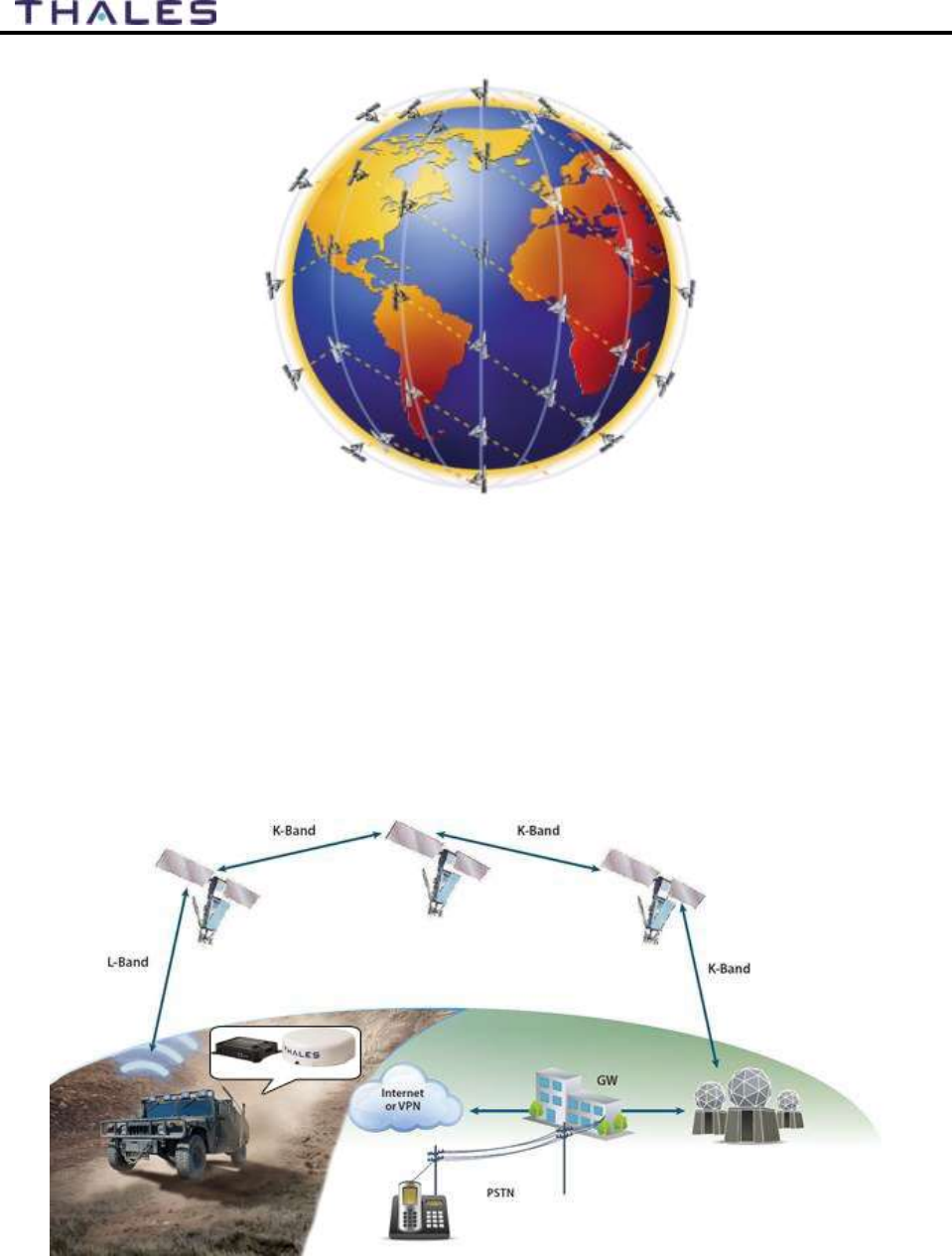
THE IRIDIUM SATELLITE NETWORK
The Iridium satellite network is comprised of 66 Low-Earth Orbiting (LEO), cross-linked
satellites, providing voice and data coverage over Earth’s entire surface. The satellites operate in
six orbital planes, 781 kilometers (485 miles) from Earth. Each orbital plane has 11 satellites.
Each satellite completes one orbit around Earth every 100 minutes, traveling at a rate of 16,832
miles per hour. There are spare satellites in orbit ready to replace a non-functioning satellite.
Iridium has gateways in Arizona, Alaska and additional telemetry, tracking and control facilities
in Canada and Norway. It is the largest commercial satellite constellation in the world.
This constellation ensures that every region on the globe is covered by at least one satellite at all
times. Each satellite is cross-linked to four other satellites; two satellites in the same orbital plane
and two in an adjacent plane.
The Iridium NEXT satellite constellation replaces the older Block 1 Iridium satellite
constellation and supports faster data rates, more capacity and better voice quality.
1-2
User Manual PN 84468 Rev 1
Figure 1-1 Earth showing Iridium satellites in six defined orbital planes.
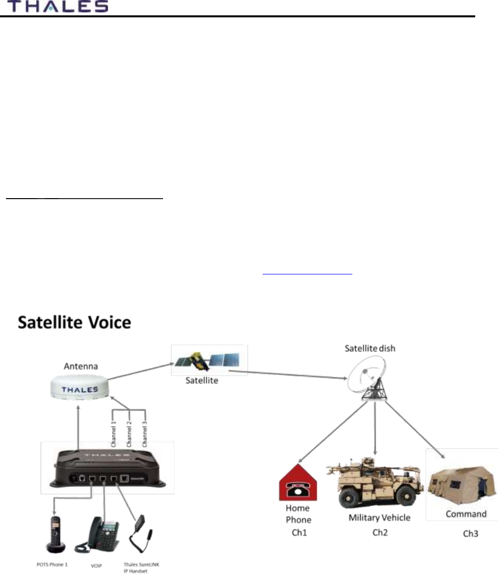
Figure 1-2 shows a typical flow over the Iridium network of a call made from the MissionLINK
system.
A MissionLINK voice or data call is sent to the closest satellite overhead that has a high signal
strength. The traffic is then routed through the satellite network until it lands at the Alaska
Ground Station, and, is then routed over terrestrial networks to the Gateway in Arizona. At the
gateway, traffic is converted back to internet protocol (IP) and voice, depending on call type and
delivered to the IP cloud or the public switched telephone network (PSTN).
Figure 1-2 Typical Iridium Network Flow of a Voice or Data Call.
2-1
User Manual PN 84468 Rev 1
SYSTEM OVERVIEW CHAPTER 2
DESCRIPTION
The MissionLINK system operates using Iridium Certus™ broadband services over a network of
66 satellites that cover 100% of the globe, including remote locations and the poles. The solution
utilizes this robust network service to provide highly reliable, mobile and essential voice, text
and web communications. For best operation, a clear view of the sky is necessary as satellites
can be as low as eight degrees above the horizon. The service capabilities of the system are
outlined below.
Certus™ Multi-Services Platform
Satellite data sessions up to 352kbps (current) & 700kbps (available 2019)
Streaming up to 256kbps (available 2019)
3 high quality voice lines
Short Burst Data (future)
Location tracking service with subscription at www.clrSight.com
Figure 2-1 Three Channel Voice Calling Overview

2-2
User Manual PN 84468 Rev 1
Primary System Features
Embedded 802.11b/g/n Wi-Fi access point with five (5) simultaneous users.
Intuitive Management Portal user interface for configuration, monitoring and system
status.
Application Programming Interface (API) for remote management and issue resolution.
PBX (Private Branch Exchange) functionality provides free local calling for local calling.
(Figure 2-2).
Least Cost Routing automatically switches the data path to an external non-Iridium
network (i.e., cellular, Wi-Fi, etc.) for faster, lower cost transmission when connected
(Optional).
Custom Thales softphone application available in the Apple Store and Google Play for
use on iOS and Android devices.
Low profile, IP66 rated antenna with single RF cable to the Terminal Unit (TU).
Magnetic mount kit for easy antenna installation.
Radio Gateway feature allows Land Mobile radios to access the satellite voice network.
Ruggedized tethered Thales SureLINK IP Handset for system configuration, monitoring
and voice calls (optional).
Supported WEB Browsers:
o Internet Explorer
o Chrome (Blink)
o Safari (Webkit)
o Firefox
o Android
o iOS (Safari)
Figure 2-2 Local Communications via PBX Functionality
2-3
User Manual PN 84468 Rev 1
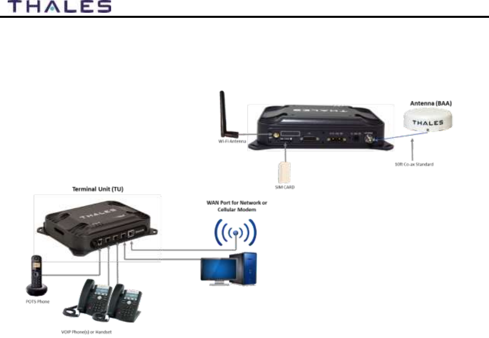
A typical user setup that includes the standard kit items as well as a POTS phone, VoIP phones
and a computer is shown in Figure 2-3. A cellular modem can be connected to the WAN port for
data least-cost routing operations. Voice calls are always routed through the Iridium satellite
system.
Figure 2-3 MissionLINK System with Connected Hardware
2-4
User Manual PN 84468 Rev 1
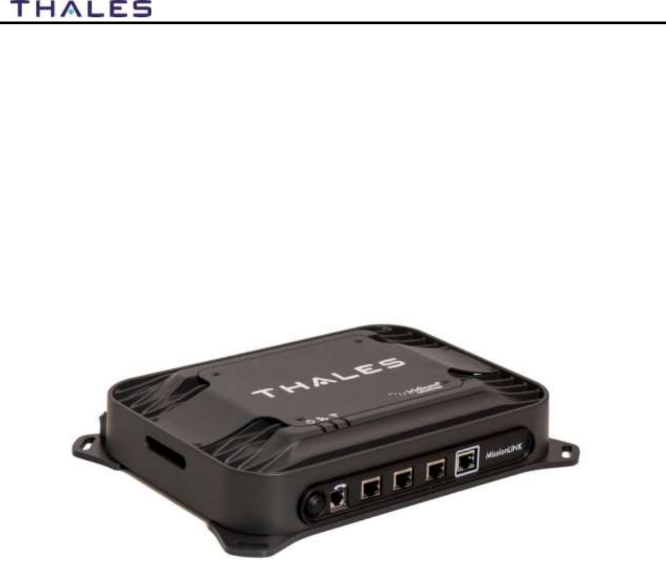
Terminal Unit (TU)
The Terminal Unit (TU) supports voice and data communications in a land mobile or terrestrial
fixed environment. The TU is capable of supporting wireless voice and data that links the user
with the Iridium satellite network. The TU, depending on Line of Site (LOS) and LEO
Satellites, will be able to maintain satellite connectivity while experiencing conditions varying
from urban canyons to high vibration from road movement. As a wireless access point, the TU
provides Wi-Fi (802.11) access for data and Voice over IP (VoIP) calls. Three RJ-45 Ethernet
connectors and one RJ14 jack enables the user to tether directly to the TU, if desired. The
Management Portal is a graphical user interface that can be used to modify system settings and
indicate system status. The TU is powered by an included DC power cable with a 10-32V
input range, accommodating all types of vehicles and battery types. It also can be powered by
an optional 12 Volt AC to DC power source for fixed applications where AC power or a DC
power inverter is available.
Figure 2-4 Terminal Unit (TU)
2-5
User Manual PN 84468 Rev 1
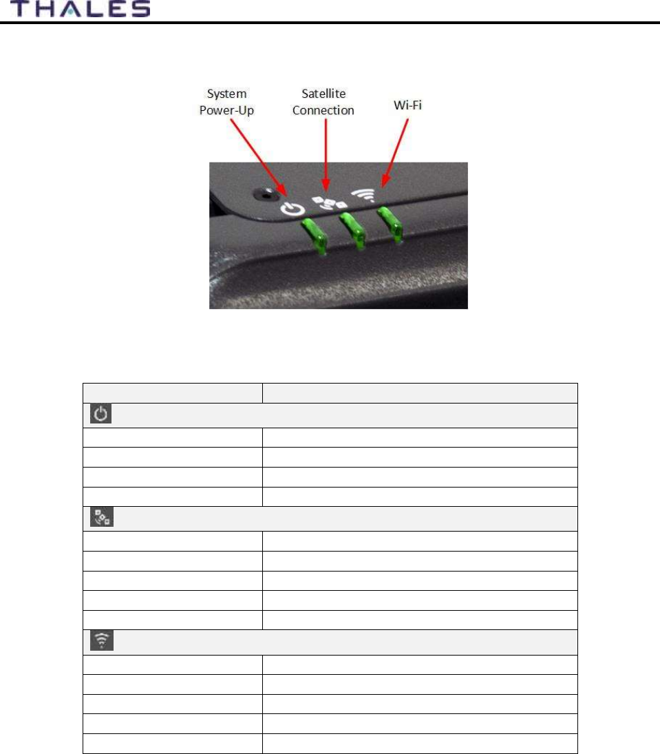
The Terminal Unit has three status LEDs on the top of the unit that indicate status of system
power-up, satellite connection and the Wi-Fi.
Figure 2-5 Terminal Unit (TU) LEDs
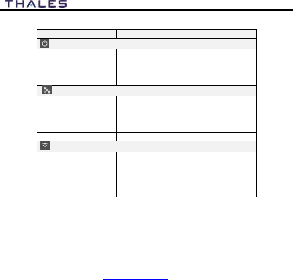
Table 2-1 Terminal Unit LED Status
Indicator
Description
System
Solid GREEN
System functioning properly
Flashing GREEN
System busy (Booting up)
Solid RED
Fault (minor issue)
Flashing RED
Critical fault (major issue)
Satellite
Solid BLUE
Connected and passing data (over satellite)
Solid GREEN
System functioning properly
Flashing GREEN
Acquiring satellite
Solid RED
Fault (minor issue)
Flashing RED
Critical fault (major issue)
Wi-Fi
OFF
Wi-Fi OFF
Flashing GREEN
Wi-Fi busy
Solid Green
System functioning properly
Solid RED
Fault (minor issue)
Flashing RED
Critical fault (major issue)
2-6
User Manual PN 84468 Rev 1
NOTE
The Indicator Colors are:
Solid Green: all is OK
Flashing Green: start-up or in progress of configuring or acquiring
service.
Solid Red: fault requires user attention (Open Management Portal for
Alerts)
Flashing Red: critical fault requiring immediate attention (Open
Management Portal and contact service provider.)
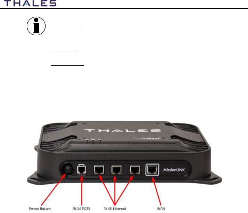
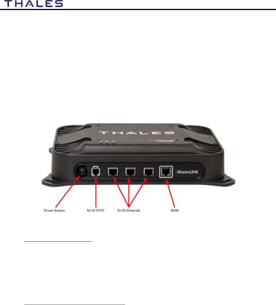
The Terminal Unit front panel (left to right) has a main power button, one RJ-14 jack for POTS
(Plain Old Telephone Service) Phone(s), three PoE (Power over Ethernet) RJ-45 connections for
VoIP phones or Ethernet-based devices, and one WAN (Wide Area Network) connection
primarily used to connect an external cellular modem or VSAT.
Figure 2-6 Terminal Unit (TU) Front Panel Detail
2-7
User Manual PN 84468 Rev 1
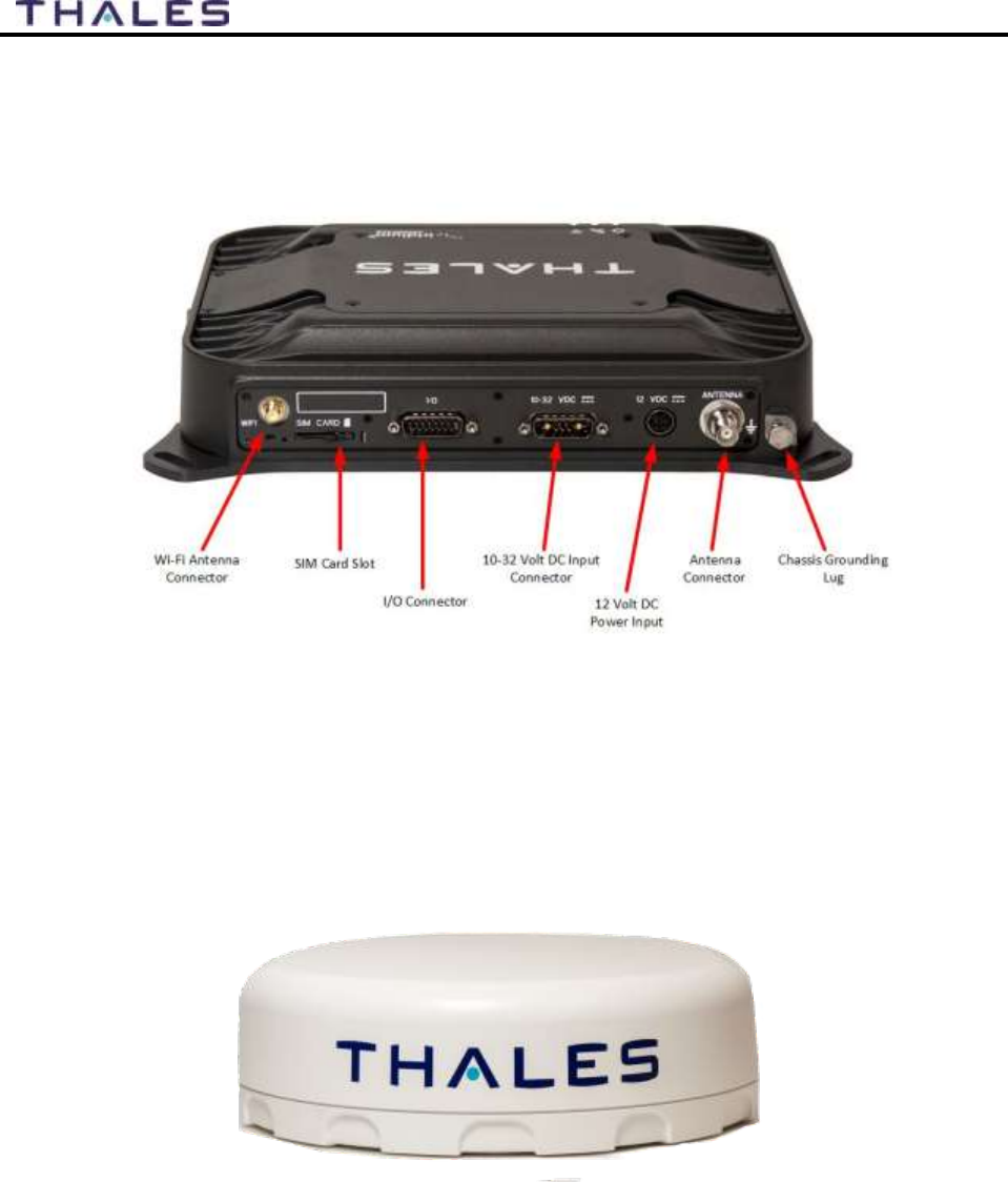
The Terminal Unit back panel (left to right) has a Wi-Fi antenna connector, SIM Card slot, GPIO
(I/O) connector, 10-32Volt DC input connector, 12Volt DC power input, antenna connector, and
chassis grounding lug.
Figure 2-7 Terminal Unit (TU) Back Panel Detail
Broadband Active Antenna (BAA)
The BAA is a standalone unit that connects to the Terminal Unit through a single coaxial cable.
DC power, RF transmit and receive signals, control data and GPS data are communicated
between the BAA and Terminal Unit using this single coaxial cable.
Figure 2-8 Broadband Active Antenna (BAA) Unit
3-1
User Manual PN 84468 Rev 1
GETTING STARTED CHAPTER 3
GETTING STARTED
STEP 1: Connect Phone (standard POTS handset) or Ethernet VOIP Phone to Terminal
Unit (TU).
The TU front has a main power button, one RJ-14 port for POTS (Plain Old Telephone
Service), three PoE (Power over Ethernet) RJ-45 ports for VoIP phones or Computers,
and one WAN (Wide Area Network) port. Refer to Figure 3-1 for location of ports.
Figure 3-1 Terminal Unit (TU) Front Panel Detail
POTS Phone connection
By default, the POTS Phone can simply be plugged into the RJ-14 port using a standard
phone cord (not provided) without any setup.
The TU can accept up to 2 POTS Phones can be connected to the TU using a RJ-14
Splitter (not provided). Using a RJ-14 Splitter, the two POTS phones can each have a
separate phone line (not two phones using the same phone line).
VoIP or Thales IP Phone connection
By default the TU has (3) lines preconfigured for use with POTS phones, VoIP phones,
or Thales SureLINK IP Handsets, as shown in Table 3-1. If using a VoIP phone, Thales
recommends CISCO SPA504G and Grand Stream GXP2140 models for ease of use with
MissionLINK. Other brands and models may be supported but functionality cannot be
guaranteed.
Follow your VoIP phone configuration guide to setup the VoIP phone and connect to the
TU using the following parameters.
Table 3-1 Typical VoIP Phone Configuration
3-2
User Manual PN 84468 Rev 1
Extension 1: (receives calls on line
1 of your SIM)
User: "1001"
Password: "1001"
Host: "sip.thaleslink"
Protocol: udp or tcp
Extension 2:(receives calls on line
2 of your SIM)
User: "1002"
Password: "1002"
Host: "sip.thaleslink"
Protocol: udp or tcp
Extension 3:(receives calls on line
3 of your SIM)
User: "1003"
Password: "1003"
Host: "sip.thaleslink"
Protocol: udp or tcp
NOTE
By default, extensions 1 and 2 are mapped to POTS phone
connections and Extension 3 is flexible and VoIP phone or
Thales SureLINK IP Handset can be used if configured as noted
in Table 3-1.
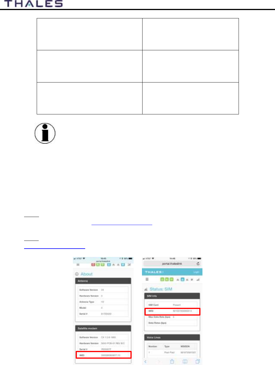
STEP 2: Know your MissionLINK
It may be necessary to know details about your MissionLINK system when calling for
help or service.
IMEI is unique to each unit and can be found on the bottom plate of the TU. This IMEI
can also be found in the http://portal.thaleslink under the ABOUT tab.
IMSI is a unique identifier to each SIM card. This IMSI can also be found in the
http://portal.thaleslink under the STATUS SIM tabs. (SIM must be inserted)
Figure 3-2 MissionLINK IMEI and IMSI from Mobile Device
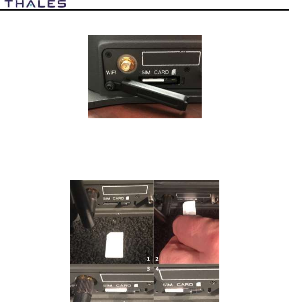
STEP 3: Install SIM
3-3
User Manual PN 84468 Rev 1
1. Open the SIM Card Slot (Figure 3-3).
Figure 3-3 SIM Card with Cover Opened
2. Install SIM card from Air-time provider (1, Figure 3-4), by inserting the card with
contacts down (2) until it clicks into place (3).
3. Be sure to engage the lock for the SIM Card (4).
Figure 3-4 Installing SIM Card and Engaging the Lock
3-4
User Manual PN 84468 Rev 1
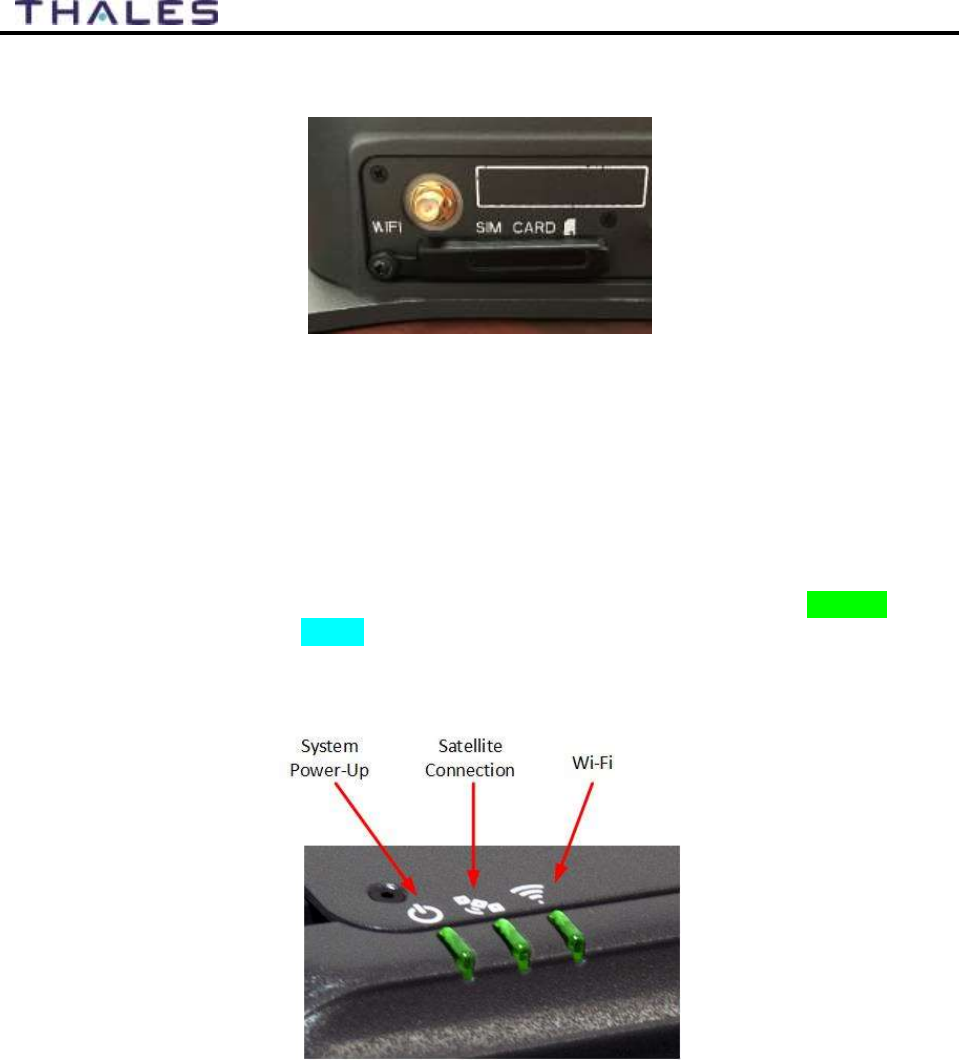
4. Secure the SIM Cover once the SIM Card has been locked into place. (Figure 3-5)
Figure 3-5 Secure the SIM Card Cover
STEP 4: Power the MissionLINK unit.
Before powering the unit, make sure the DC power cable is connected to a 10-32VDC
source, the polarity is correct, and the DC cable is securely connected to the TU. The
antenna must also be connected per the installation manual. Power the unit by pressing
and releasing the power button on the TU (Figure 3-1). NOTE: After the button is pressed
and released, a few seconds pass before the System LED (left) starts flashing. It may take
a few minutes on initial startup for all 3 LED’s on the unit top to turn solid GREEN (or
middle LED may turn BLUE). You may see an occasional red LED during power up.
This is normal as long as after it has fully booted, it stays green or turns blue. Refer to
Table 3-2 for more information on the status LEDs.
Figure 3-6 System, Satellite and Wi-Fi Status LED’s
3-5
User Manual PN 84468 Rev 1
Table 3-2 Terminal Unit LED Status
Indicator
Description
System
Solid GREEN
System functioning properly
Flashing GREEN
System busy (Booting up)
Solid RED
Fault (minor issue)
Flashing RED
Critical fault (major issue)
Satellite
Solid BLUE
Connected and passing data (over satellite)
Solid GREEN
System functioning properly
Flashing GREEN
Acquiring satellite
Solid RED
Fault (minor issue)
Flashing RED
Critical fault (major issue)
Wi-Fi
OFF
Wi-Fi OFF
Flashing GREEN
Wi-Fi busy
Solid Green
System functioning properly
Solid RED
Fault (minor issue)
Flashing RED
Critical fault (major issue)
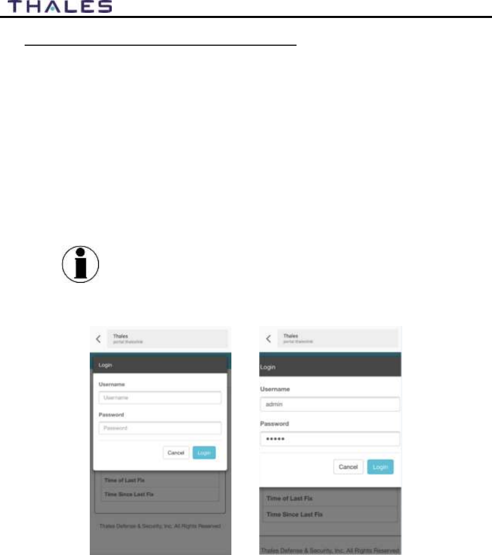
STEP 5: Connect to MissionLINK portal to configure system.
Reference Figure 3-7. There are a couple options to login to the Management Portal.
Option A: Via Wi-Fi.
1. Power on the MissionLINK TU and let it boot up (may take a couple minutes).
2. On the wireless device, find and select THALESLINK (default) or other SSID name the
MissionLINK has been configured to as an available Wi-Fi access point.
3. Open a browser and type: http://portal.thaleslink (do not type .com or any other
extension)
4. Once the Management Portal opens, click LOGIN button. Enter “admin” for Username
and “admin” for Password.
5. As a default, no changes to setup are necessary, but advanced users may want to
configure their preferred system settings.
6. At this time, it is advised that you change the username and password. To change
password: Go to SETTINGS GENERAL and change the password for the “Admin”
user.
3-6
User Manual PN 84468 Rev 1
Option B: Via (PC, Mac or Linux) Ethernet connection
1. With your computer connect the Ethernet RJ-45 Cable (included) to any of the 3 Ethernet
ports on the TU. (Shown on Figure 2-6) (Do not connect to the WAN port on the TU)
2. Via the network settings on your computer’s operating system, select and connect to
ThalesLINK connection.
3. Open a web browser and type: http://portal.thaleslink (do not type .com or any other
extension)
4. Once the Management Portal opens, click LOGIN button. Enter “admin” for Username
and “admin” for Password.
5. As a default, no changes to setup are necessary, but advanced users may want to
configure their preferred system settings.
6. At this time it is advised that you change the username and password. To Change
Password: Go to SETTINGS GENERAL and change the password for the Admin
User.
NOTE
If you forget the password, press and hold the reset pin on the
back of the box (while powered on) in order to reset the system
to factory settings. All custom configuration settings will be lost.
Figure 3-7 MissionLINK User Interface Login

3-7
User Manual PN 84468 Rev 1
STEP 6: Place a phone call.
1. Choose either POTS or VoIP handset.
2. Lift the handset from the base and listen for a dial tone.
3. For all calls, dial 9 first
4. Call a known number to test call and voice clarity
A test number is Call: 9-5555
STEP 7: Access the Internet.
Once your device has successfully connected to the TU, open the Management Portal
http://portal.thaleslink to verify the satellite connection.
Verify:
• No active alerts (DASHBOARD or ALERTS page on the Management Portal)
• Satellites detected (go to STATUS SERVICE), signal strength bars (top right of
screen) should show more than 1 bar as available.
Try loading a small website such as www.google.com to verify your internet connection.
If the page loads successfully you are ready to browse the internet.

4-1
User Manual PN 84468 Rev 1
THALES MANAGEMENT PORTAL CHAPTER 4
NOTE
To access the Management Portal from a laptop:
Power on the Thales MissionLINK TU and let it boot up
(may take a couple minutes)
Open a web browser
Type: http://portal.thaleslink (do not type .com or any
other extension)
The Management Portal appears in “guest” mode.
To make changes, log in as an administrator by selecting
LOGIN at the top of the window
When prompted, enter the default Username (admin) and
Password (admin)
Immediately change the Password for added security
(SETTINGSGENERAL)
NOTE
To access the Management Portal from a wireless device using
Wi-Fi:
Power on the MissionLINK TU and let it boot up (may
take a couple minutes)
On the wireless device, find and select THALESLINK as
an available Wi-Fi access point.
Open a browser and type: http://portal.thaleslink (do not
type .com or any other extension)
The Management Portal appears in “guest” mode.
To make any changes, log in as an administrator by
selecting LOGIN at the top of the window
When prompted, enter the default Username (admin) and
Password (admin)
Immediately change the Password for added security
(SETTINGSGENERAL)
GETTING TO KNOW THE THALES MANAGEMENT PORTAL
The Thales Management Portal is a graphical user interface with an intuitive menu structure that
is used to configure and monitor the MissionLINK system. The Management portal provides
key information and status alerts about the operation and condition of the system and Iridium
network. The Thales Management Portal is resident on the TU and can be accessed and viewed
on almost any smart device or computer including phones, tablets, laptops, desktop computers,
and the optional Thales SureLINK IP Handset. The menu structure and content will
automatically scale to the device’s screen size. The descriptions below are applicable for all
devices but screen shots apply to larger display devices such as laptop computers. The actual
view may vary depending on the size of the screen being used.

4-2
User Manual PN 84468 Rev 1
The Thales Management Portal is the primary user interface for the MissionLINK system. There
are four access levels to the system. Three of them are under password control.
Local access levels include GUEST access, which is for general users of the system that
do not need to make configuration changes.
The second local access is for administrators who need to view all data, perform software
updates and make configuration changes.
The first remote access level is for remote users who need to monitor the system, but no
configuration changes are permitted. This is similar to the “guest” access except that it is
a remote user instead of a local user.
The second remote access level is for remote administrators such as Service Providers.
This level allows for viewing all data and making configuration changes through the
custom Thales Application Programming Interface (API).
The guest access level is not password protected, so when the Management Portal is opened, the
guest user can view the current configuration and status of the system and any alerts that have
been generated, but cannot change any parameters. The three other access levels are password
protected. Passwords can be controlled and changed by the administrator in the SETTINGS
GENERAL menu, where the local administrator is denoted as “admin”, the remote user is
denoted by “wan_user” and the remote administrator is denoted by “wan_admin”. By password
control, the local system administrator can enable or prevent any remote access to the system.
Administrators, after initially logging in with the default Username (admin) and Password
(admin), can view all data and also make changes to all the configuration settings to customize
the MissionLINK system. It is highly recommended that the administrator creates a new
Password immediately after signing in with the default username and password for added
security and protection.
In the following pages, the Thales Management Portal is described in detail. Read through the
entire contents before attempting to configure the TU for the first time.
When you first enter into the Thales Management Portal, menu items appear on the left side of
the screen (see Figure 3-1). Each of these menu items is discussed in the following sections. A
short description of each menu item is below.
Status – Provides status of each of the items listed below. These screens cannot be edited
and are provided for information only.
o Current Devices
o GPS
o LAN
o Phones
o Services
o SIM
Alerts – Provides a listing of system alerts
Calls – Provides information relating to Calls, including current calls, call history, and
call management.
4-3
User Manual PN 84468 Rev 1
Distress – Allows the operator to send a distress message.
Settings – Enables the Administrator to configure parameters/ settings for sending
messages, using Wi-Fi, WAN, LAN, Satellite, data, and phone.
System – Enables the Administrator to perform system backups, view data usage, reset
the system, and view/update system firmware.
Diagnostics – Enables the administrator to run a self-test, check system status, and view
diagnostics logs entries.
About – Provides system level information for the antenna, modem, power supply,
system, VOIP Module, and Wi-Fi.
Help – Provides a link to the MissionLINK User Documentation (Users Guide,
Installation Instructions, and Quick Start Guide (QSG)).
Menu Components
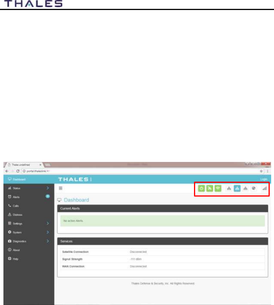
The System Status Icons at the top of the screen, highlighted in Figure 4-1, provide system level
information that is useful to the user. When selected, these icons provide addition screen(s) of
information and a quick way to make certain configuration setting changes by the administrator.
Figure 4-1 Quick Link Icons
4-4
User Manual PN 84468 Rev 1
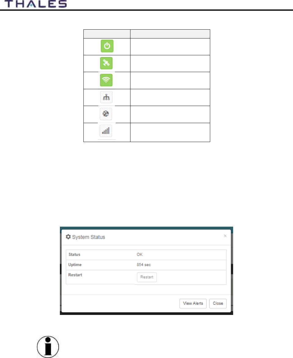
Table 4-1 Quick Link Icons
ICON
Description
System Status
Satellite Status
WI-FI Status
LAN 1, 2, and 3 Status
WAN Status
Satellite Signal Strength
System Status – The System Status icon provides a quick view of the state of the system.
It mirrors the status of the System LED on the TU. Selecting the System Status icon
brings up the additional information in Figure 4-2.
o STATUS shows the current condition of the system.
o UPTIME indicates how long the terminal has been in use.
o The RESTART button allows an administrator to reboot the terminal.
o Selecting VIEW ALERTS opens the ALERTS window and displays any Current
Alerts.
Figure 4-2 Quick Link – System Status
NOTE
If the system requires a RESTART, the operator can simply
press RESTART to reboot the terminal. Once the system has
rebooted, verify that you are connected to the WI-FI for the
terminal. Once you are connected to the terminal, you will be
prompted to reenter the user name and password.
4-5
User Manual PN 84468 Rev 1
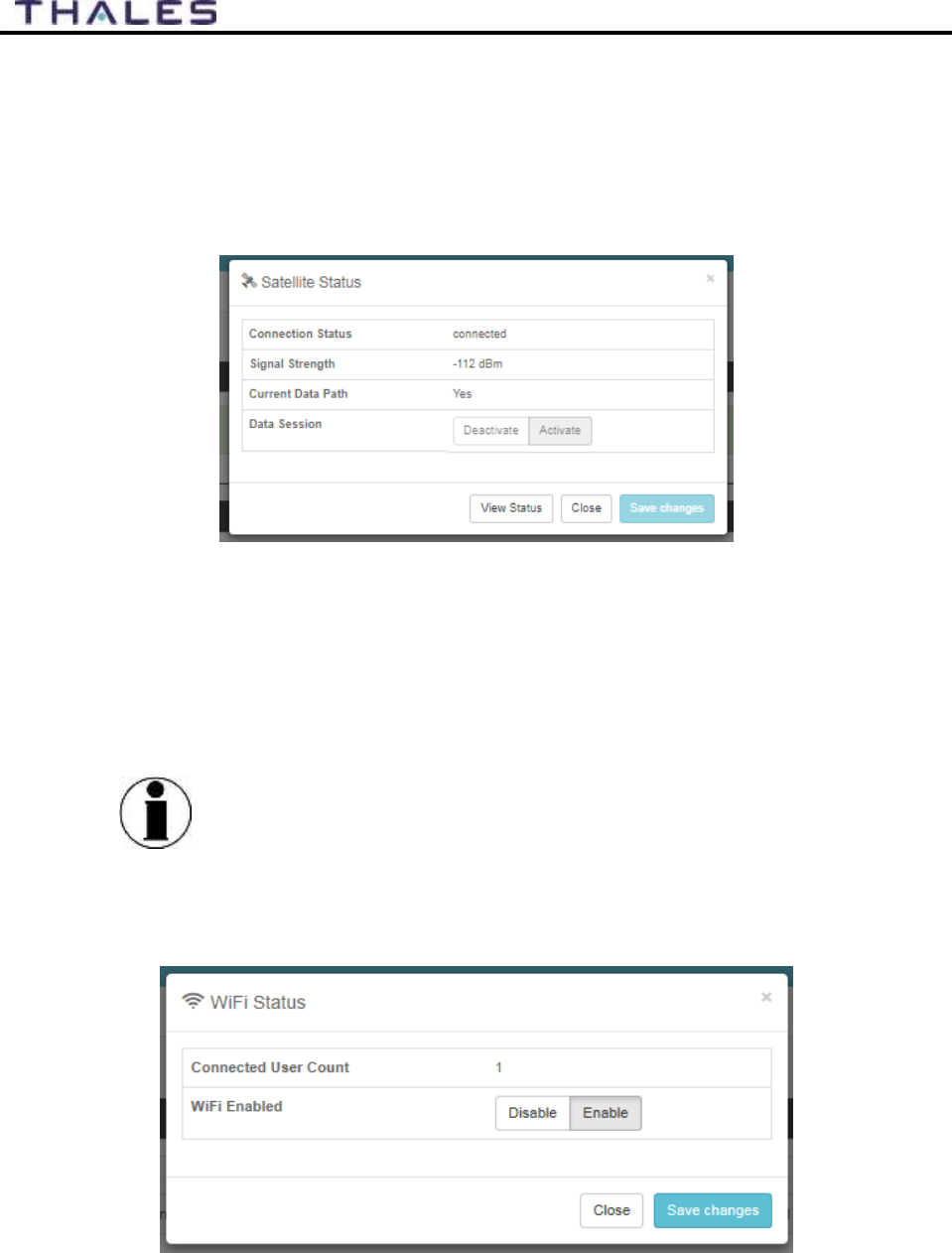
Satellite Status – The Satellite Status icon provides a quick view of the Satellite Status. It
mirrors the status of the Satellite LED on the TU. Selecting the Satellite Status icon
displays the information in Figure 4-3, showing “Connection Status”, “Signal Strength”
and the “Current Data Path”. Selecting ACTIVATE / DEACTIVATE enables and
disables data sessions. Changes will take effect once SAVE CHANGES is selected.
Selecting VIEW STATUS will open the STATUS SERVICES Window.
Figure 4-3 Quick Link – Satellite Status
Wi-Fi Status – The Wi-Fi Status icon (Figure 4-4) provides a quick view of the Wi-Fi
status. It mirrors the Wi-Fi LED on the TU. Selecting the Wi-Fi Status icon displays the
CONNECTED USER COUNT (number of users connected to the ThalesLINK Wi-Fi)
and allows an administrator to ENABLE / DISABLE the Wi-Fi connection. Changes
will only take effect once SAVE CHANGES is selected.
NOTE
If connected to the terminal through a Wi-Fi connection,
disabling the Wi-Fi causes loss of the Wi-Fi signal and removal
from the wireless device’s Wi-Fi menu. To regain use of the Wi-
Fi, connect a computer via supplied Ethernet cable to the TU,
open the Management Portal, select the Wi-Fi Status icon and
select ENABLE.
Figure 4-4 Quick Link – Wi-Fi Status
4-6
User Manual PN 84468 Rev 1
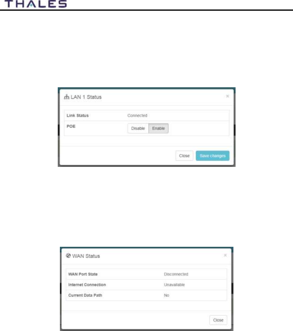
LAN Status Icons – The LAN Status icons (LAN 1, LAN 2 and LAN 3) provide a quick
view of each LAN’s Status. Each LAN icon is highlighted in blue when a device is
plugged into it. By selecting a LAN icon, the additional information in Figure 4-5 is
shown, displaying the “Link Status” and allowing for ENABLE / DISABLE of the Power
over Ethernet (PoE) for that LAN. Changes will only take effect once SAVE CHANGES
is selected.
Figure 4-5 Quick Link – LAN 1 Status (LAN 2 and LAN 3 similar)
WAN Status – The WAN Status icon provides a quick view of the current connection
status of the WAN port. The WAN Status icon will be highlighted in blue when an
external WAN device is plugged into it. By selecting the WAN icon, the additional
information in Figure 4-6 is shown. The details provided on this screen are for
information only and include WAN PORT STATE, INTERNET CONNECTION, and
CURRENT DATA PATH.
Figure 4-6 Quick Link – WAN Status
Signal Strength Icon – Displays the satellite signal strength as 5 vertical bars. More bars
are highlighted as the signal strength rises.
4-7
User Manual PN 84468 Rev 1
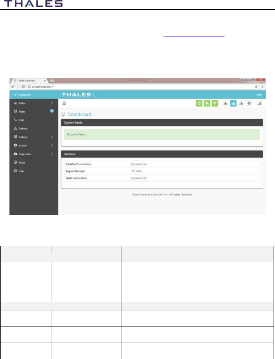
Main Dashboard
When first accessing the Management Portal by typing in http://portal.thaleslink, the Dashboard
screen comes up by default. The Dashboard can also appear by selecting the top menu item
highlighted in blue in Figure 4-7. From the Dashboard, you can see information relating to:
Current Alerts
Services
Figure 4-7 Thales MissionLINK Dashboard - Main Screen
Table 4-2 Thales MissionLINK Dashboard - Main Screen
Section
Value
Description
Current Alerts
Alert Name
Text
Provides information relating all system issues
summarized for easy reporting and
debug/troubleshooting.
For additional information, refer to Chapter 6
Troubleshooting
Services
Satellite
Connection
Disconnected or
Connected
Displays whether or not the system is connected to a
satellite
Signal Strength
Indicates the strength
of the signal
Displays the current satellite signal strength in dBm
WAN
Connection
Disconnected or
Connected
Displays whether or not a WAN device is plugged
into the TU and is connected to the internet
4-8
User Manual PN 84468 Rev 1
Status
NOTE
The STATUS selection screens (CURRENT DEVICE, GPS,
LAN, PHONES, SERVICES and SIM) provide information
only, and cannot be edited.
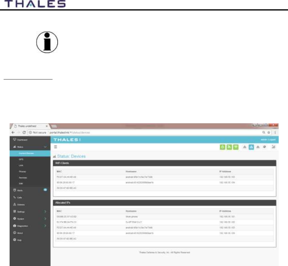
Current Devices:
Displays all devices currently connected to the TU, both wired and via Wi-Fi. WI-FI CLIENTS
list shows the MAC Address, Hostname and IP Address for the current Wi-Fi connected devices.
ALLOCATED IPS list shows the MAC address, Hostname and IP Address for all devices that
have recently been connected to the TU.
Figure 4-8 Status
Current Devices Screen
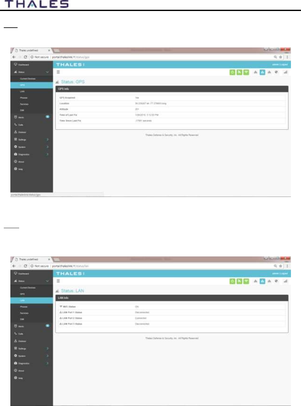
4-10
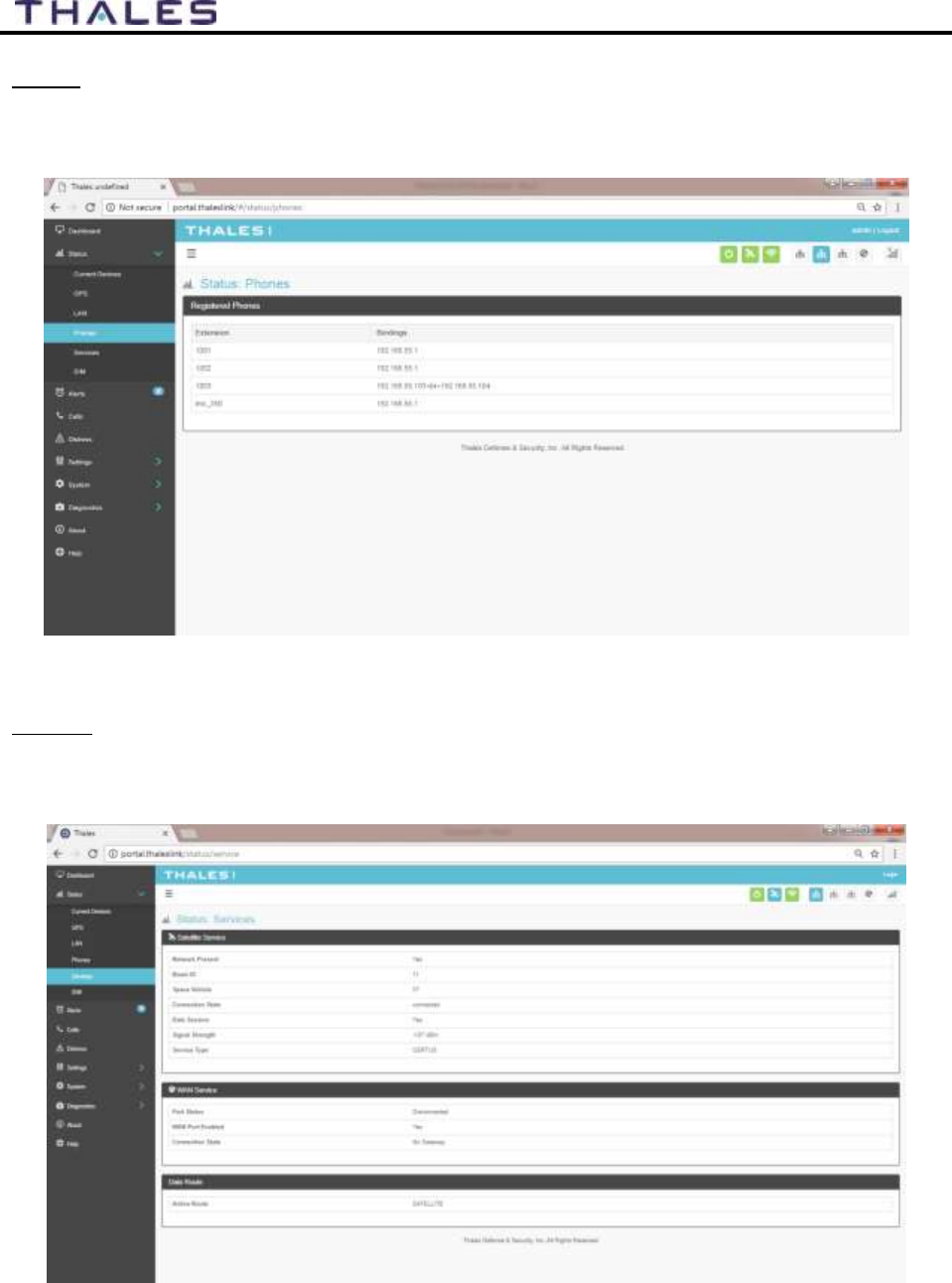
User Manual PN 84468 Rev 1
Phones
The Phone page provides a list of the registered phones that are connected to the system,
including the extension that was assigned as shown in Figure 4-11.
Figure 4-11 Status
PHONES Screen
Services
The Services page provides the status of Satellite and WAN networks, and the current data route
as shown in Figure 4-12.
Figure 4-12 Status
SERVICES Screen
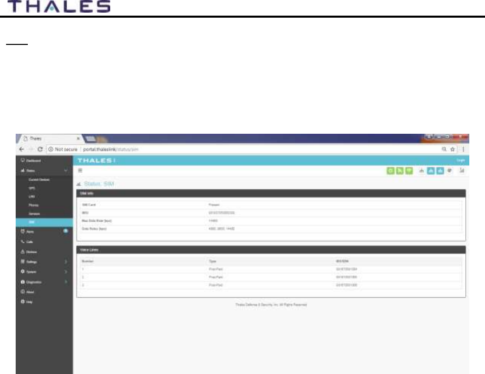
4-11
User Manual PN 84468 Rev 1
SIM
The SIM page (Figure 4-13) provides the following information:
SIM Info – Status of the SIM card, and its Unique IMSI ID number. The max data rate
shows the Certus™ service level that the SIM card is provisioned to.
Voice Lines – This section lists the dedicated Iridium voice lines (up to three), what type
they are and what their MSISDN is.
Figure 4-13 Status
SIM Screen
4-12
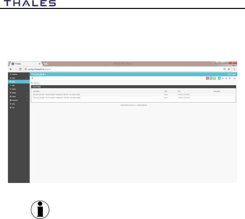
User Manual PN 84468 Rev 1
Alerts
The ALERTS screen (Figure 4-14) will display a list of active Alerts from the system. These
alerts may have been generated from a Power-On Self-Test (POST) or during normal operation
of the system. The alerts indicate that something may be wrong with the system or network. The
alerts will clear if they are no longer affecting the system operation.
Figure 4-14 ALERTS Screen (Example Shown with Active Alerts)
NOTE
For additional information, refer to Chapter 6 Troubleshooting
4-13
User Manual PN 84468 Rev 1
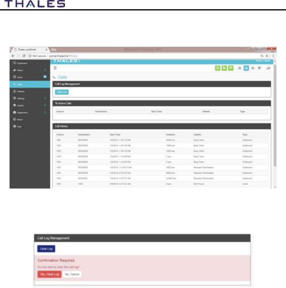
Calls
Selecting the Calls menu item (Figure 4-15) provides the call logs for active and past calls.
Figure 4-15 Call Log Screen
Under CALL LOG MANAGEMENT (Figure 4-16), the operator can CLEAR the call log by
selecting CLEAR LOG and then confirming by selecting YES, CLEAR LOG.
Figure 4-16 Call Log Management - CLEAR Call Log
4-14
User Manual PN 84468 Rev 1
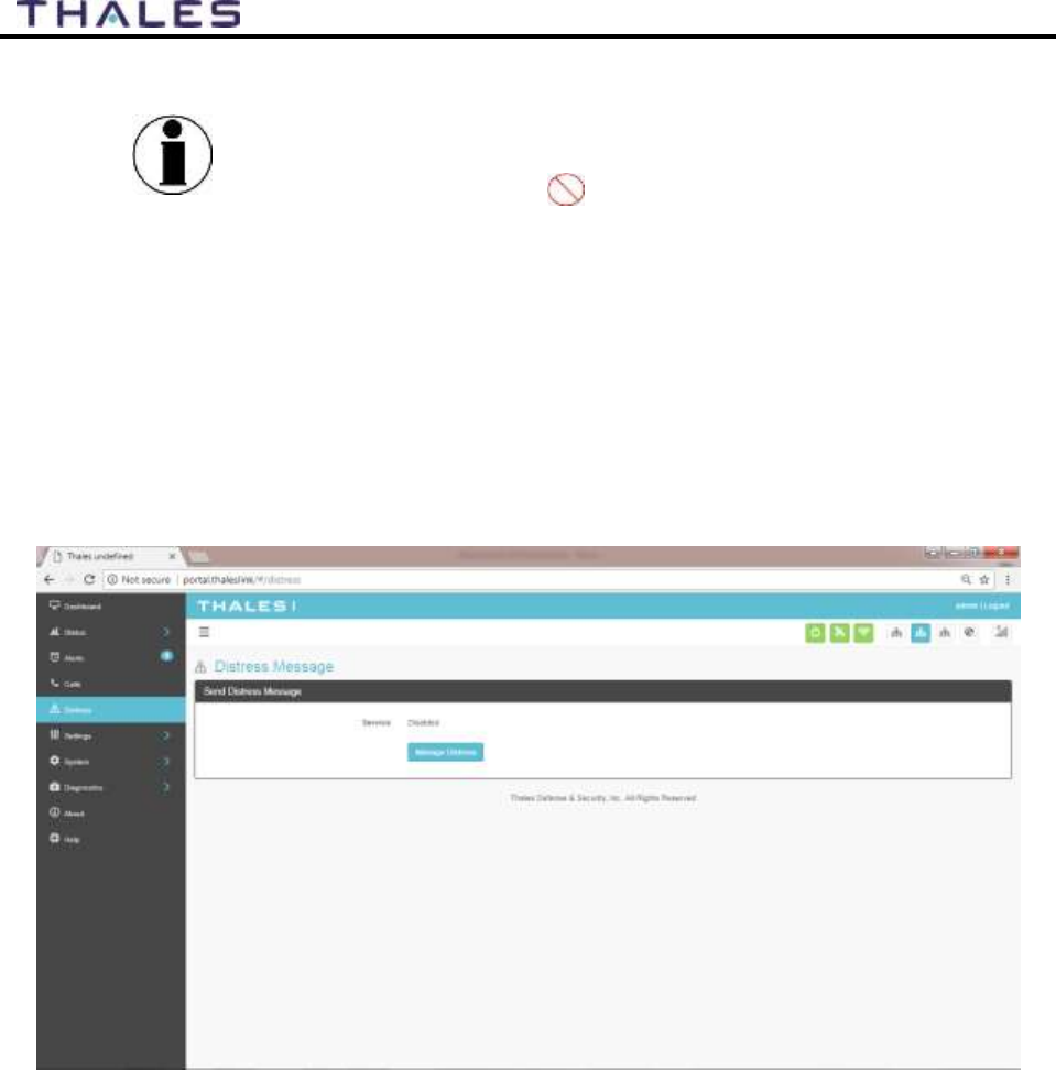
Distress
NOTE
Distress Messages can only be configured by the administrator.
If the user is not logged in as ADMIN and selects MANAGE
DISTRESS, the user will see icon, indicating this function is
not available.
The Distress Message (Figure 4-17) menu item allows for enabling and sending a distress email
message.
Selecting MANAGE DISTRESS will open the SETTING DISTRESS SIGNAL screen
(Figure 4-21). From here, set up the Distress Message by selecting Email from the drop down
box. Once the required email information has been entered, including the message to be sent,
select APPLY. For additional information, refer to SETTING DISTRESS SIGNAL.
Figure 4-17 DISTRESS (Disabled View)
4-15
User Manual PN 84468 Rev 1
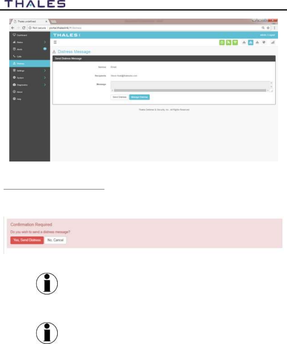
Figure 4-18 DISTRESS (Enabled View)
Sending a DISTRESS MESSAGE:
To send a DISTRESS MESSAGE, press SEND DISTRESS. A pop-up screen will appear asking
you to confirm that you want the message to be sent. Select YES, SEND DISTRESS to send or
NO CANCEL to abort the message.
Figure 4-19 Confirmation Required – Send a Distress Message
NOTE
No external indication is given when distress is activated. This
discretion is for user safety in an emergency situation. The only
indication of distress will be in Management Portal under
Distress menu item.
NOTE
A distress phone call can be made by using the optional Thales
SureLINK IP Handset. Configuration of the phone number to be
called, as well as, the activation and cancellation of the call takes
place on the handset itself. Nothing is set up for the phone call
through the Management Portal.

4-16
User Manual PN 84468 Rev 1
Settings
The Settings tab of the portal is the most important section for customizing user configurations
and feature settings. It is also advised that only experienced personnel change these setting as
they may adversely affect functionality if not set correctly. These settings are under password
control to prevent unauthorized personnel from making changes to the system.
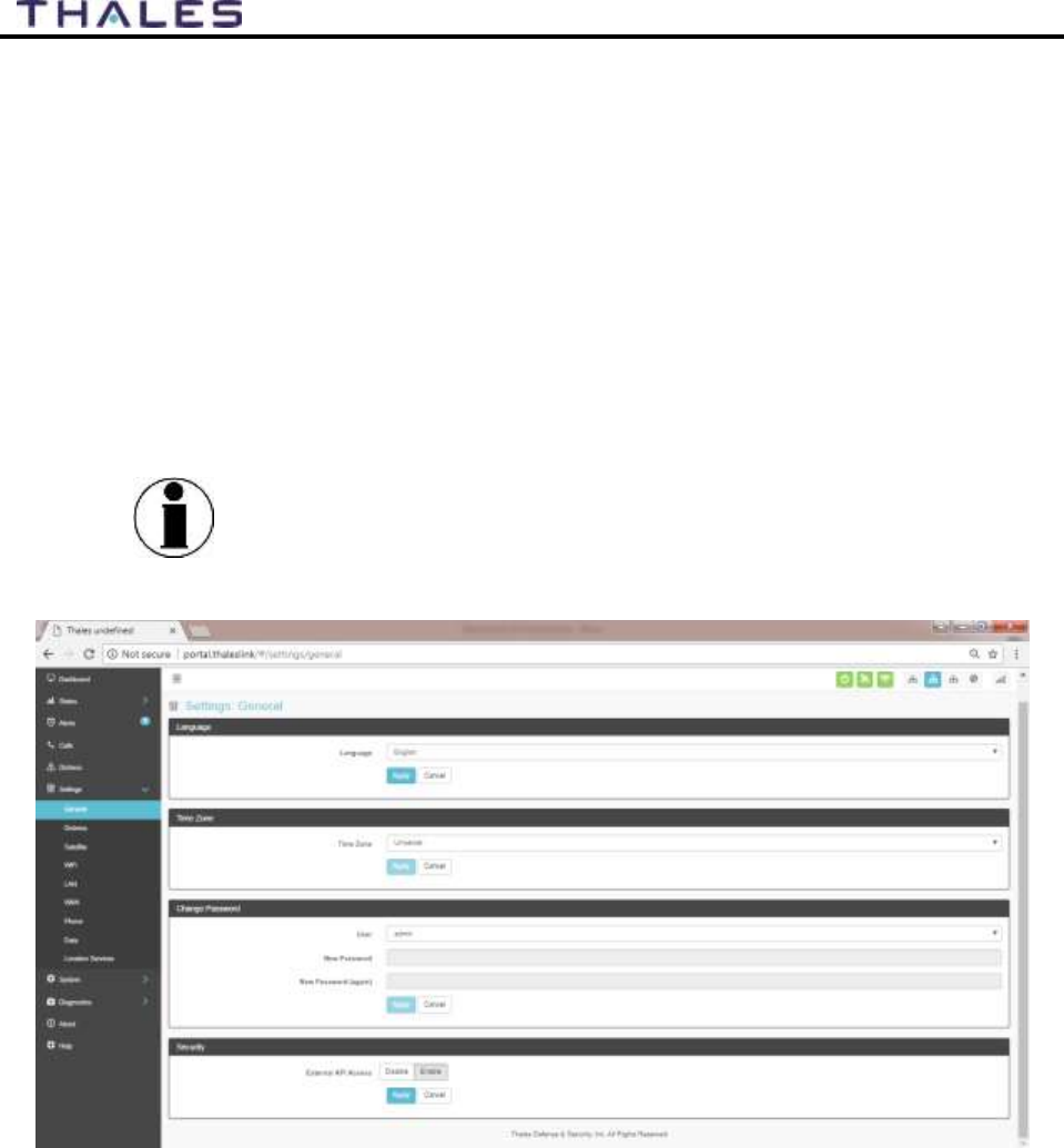
General
From the General page, the user can set the Language and Time Zone, and also change
passwords as shown in Figure 4-20 and
4-17
User Manual PN 84468 Rev 1
Table 4-3.
There are four access levels to the system. Three of them are under password control. The
passwords are managed in the Change Password section:
GUEST: User only account, no password, read only access
WAN USER: Password capability, read only access to some API data remotely via WAN
port or over the Iridium network.
WAN ADMIN: Password capability, FULL access to all data and settings remotely via
WAN port or over the Iridium network.
ADMIN: Password capability, FULL access through the Thales Management Portal via
local LAN (or wireless) connection.
NOTE
It is always recommended that passwords be changed from
defaults for added protection and security.
Figure 4-20 Settings
General Screen
4-18
User Manual PN 84468 Rev 1
Table 4-3 Settings
General Settings
Section
Parameters
Language
Select either English, French, German, or Spanish. (English is the
default setting)
Time Zone
Select the desired time zone setting from the drop down menu.
(Universal is the default setting)
Change Password
Select User, Currently there are 3 choices (Admin,
WAN_Admin, and WAN_User)
Enter NEW Password and confirm the new password (Note:
maximum length of password is 64 characters, any
combination of letters, numbers, and special characters.)
Security
Enable / Disable the external API Access. (Enable is the default
setting)
Distress
NOTE
Distress messages can only be configured by the administrator.
If the user is not logged in as ADMIN and selects MANAGE
DISTRESS, the user will see this icon, indicating this
function is not available. Login in as the ADMIN to continue.
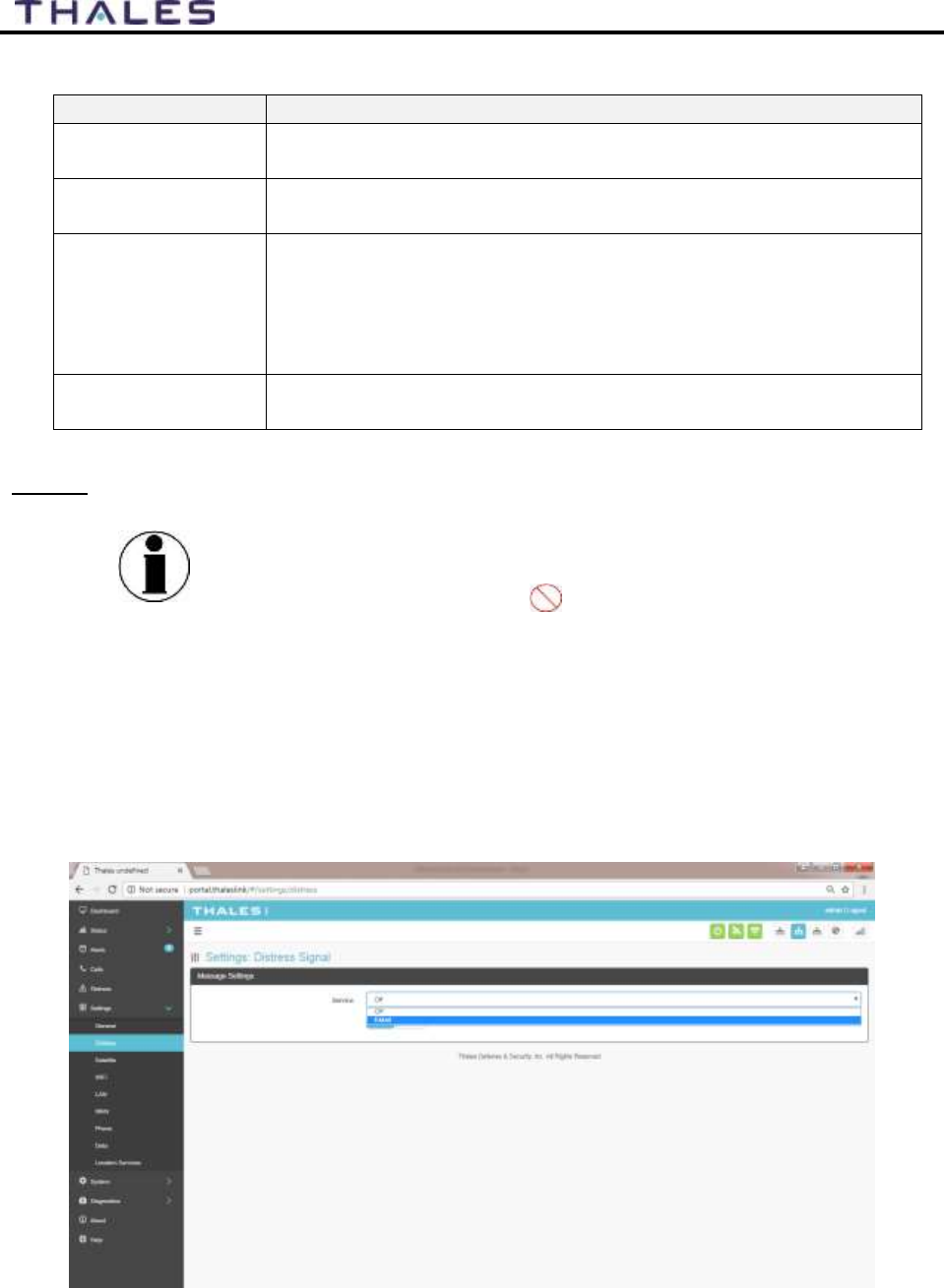
On the Distress page, the admin can set up a Distress message. The Management Portal
configuration is restricted to a distress email only. Select EMAIL from the pull down list (Figure
4-21). Enter the required information shown in Table 4-4 (example data shown in Figure 4-22)
along with the message to be sent and select APPLY. NOTE: Selecting APPLY does not send a
distress message. It saves the settings and message. Sending the distress message is done
through the DISTRESS menu item.
Figure 4-21 Settings
Distress (Initial Screen)
4-19
User Manual PN 84468 Rev 1
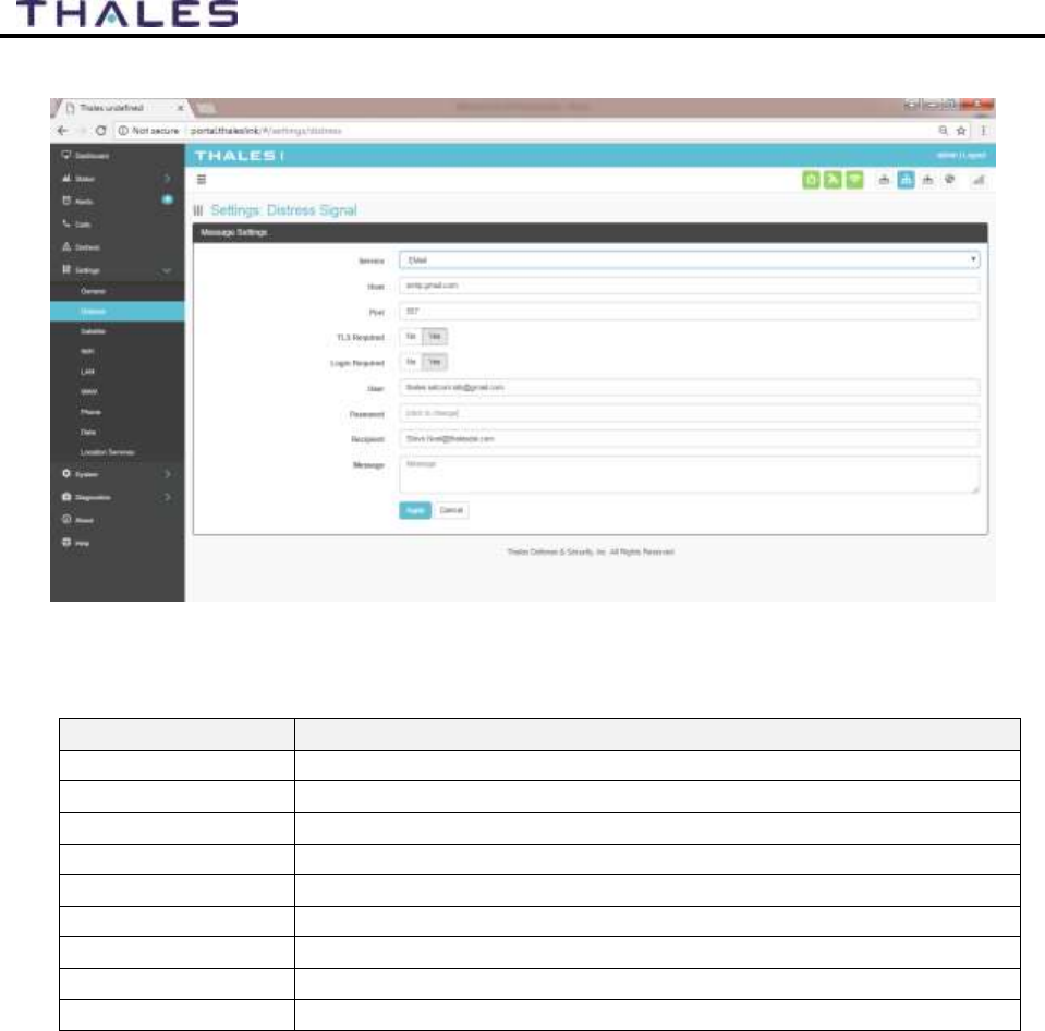
Figure 4-22 Settings
Distress
Table 4-4 Settings
Distress
Section
Parameters
Service
Select either Email or OFF (OFF is the default settings)
Host
Enter the host name (example: smtp.gmail.com)
Port
Enter the port number (example: 587)
TLS Required
Select either YES or NO (Default setting is YES)
Login Required
Select either YES or NO (Default setting is YES)
User
Enter the user email address
Password
Enter the user name password
Recipient
Enter the recipient’s email address
Message
Enter the Distress message to be sent.
4-20
User Manual PN 84468 Rev 1
Satellite
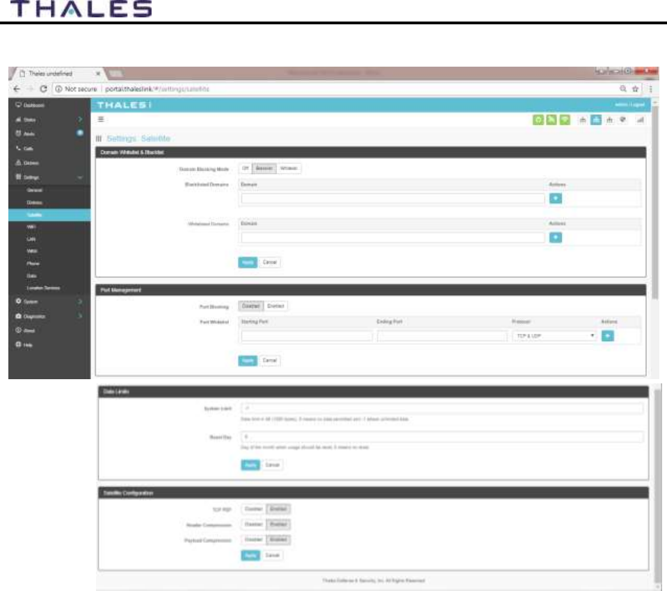
The Satellite page, shown in Figure 4-23, allows configuration of the data service. The
configuration includes configuring whitelists and blacklists for domains, configuring port
blocking and port whitelists, setting data limits for information purposes, and enabling and
disabling network compression.
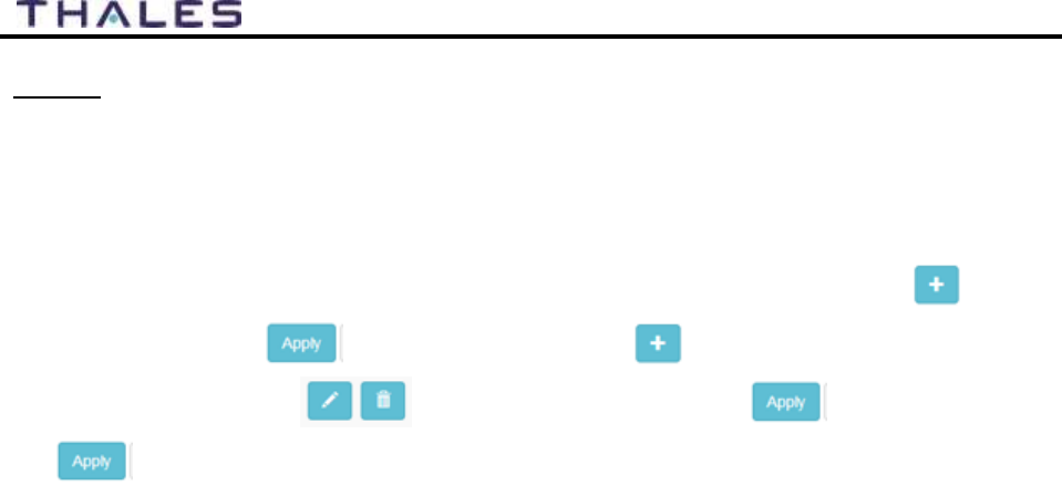
When adding a Domain to a Black/Whitelist it is always necessary to first select the button
BEFORE selecting the button. After selecting the button, the domain can always be
edited or deleted using the buttons BEFORE selecting the button to save. If
the button is not selected before leaving the Satellite menu item, the data will not be
saved.
4-21
User Manual PN 84468 Rev 1
Figure 4-23 Settings
Satellite Screen
4-22
User Manual PN 84468 Rev 1
Table 4-5 Settings
Satellite
Section
Value
Domain Whitelist & Black List
Domain Blocking
Mode
OFF / Blacklist / Whitelist (OFF is the default setting)
Blacklisting
Enabling allows ALL websites EXCEPT those listed (very little
restriction)
Whitelisting
Enabling blocks ALL websites EXCEPT those listed (the most
restriction)
Port Management
Port Blocking
Disabled / Enabled (Disabled is the default setting)
Port Whitelist
Enter the Starting Port and Ending Port number.
Select the applicable protocol (TCP & UDP or TCP only or UDP
only) (TCP & UDP is the default setting)
Data Limits
System Limit
Data limit in kB (1000 bytes), 0 means no data and -1 means
unlimited data. Setting data limits is for information purposes only.
No data restrictions will occur by setting limits.
Reset Day
Enter the day of the month when usage should be reset, 0 means no
reset
Satellite Configuration
TCP PEP
Disabled / Enabled (Default setting is ENABLED)*
Header Compression
Disabled / Enabled (Default setting is ENABLED)*
Payload Compression
Disabled / Enabled (Default setting is ENABLED)*
*NOTE: Compression enabled to increase throughput but could be a
problem for some less common and older devices
NOTE
Setting data limits is for information purposes only. Data will
not be restricted if the limit is reached or exceeded. An alert will
be generated saying that the limit has been reached.
4-23
User Manual PN 84468 Rev 1
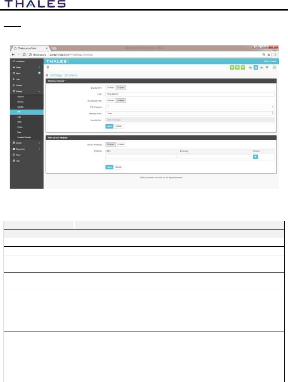
Wi-Fi
The Wi-Fi page shown in Figure 4-24 allows setup of the Wi-Fi service.
Figure 4-24 Settings
Wi-Fi Screen
Table 4-6 Settings
Wi-Fi
Section
Value
Wireless General
Enable Wi-Fi
Disabled / Enabled (Enabled is the default setting)
SSID
Enter the name of the SSID. THALESLINK is default.
Broadcast SSID
Disabled / Enabled (Enabled is the default setting)
Wi-Fi Channel
Set the Wi-Fi Channel 1 – 11
Security Mode
Set the security mode for the channel – OPEN or WPA2. OPEN is
default and does not require a Security Key (password).
Security Key
When WPA2 is selected as the security mode, a security key must be
entered. It can be any length and any combination of characters,
numbers, etc. Once enabled, any device accessing the ThalesLINK (or
new SSID name) Wi-Fi will have to enter the password.
Device Whitelist
Disabled / Enabled (Disabled is the default setting)
Whitelist
This allows specific devices to access the system’s Wi-Fi. If Enabled,
only the devices entered in the Whitelist are allowed on the Wi-Fi
network. This is done by entering the MAC address of the device
(example: 01:23:45:67:89:ab). All others are prevented from accessing
it. See below note for finding a device’s MAC address
Assign a Nickname to the MAC Address

4-24
User Manual PN 84468 Rev 1
NOTE
Once the initial Wi-Fi WPA2 Security Key is entered, it can be
changed at any time by just overwriting the current Security Key
in the SETTINGS Wi-Fi WIRELESS GENERAL area.
NOTE
To identify a device’s MAC address for whitelisting, you should
be able to find it in your device’s Settings menu. Sometimes it
is called the Wi-Fi Address. If it can’t be found, a simple way is
that while the Device Whitelist is DISABLED, connect the
device to be whitelisted to the Wi-Fi system by selecting the
correct Wi-Fi Network (SSID) and typing in the Security Code if
WPA2 is enabled. Once connected, go to STATUS
CURRENT DEVICES menu item and find the device Hostname
in the list of Allocated IPs. The MAC address will be in the left
column.
4-25
User Manual PN 84468 Rev 1
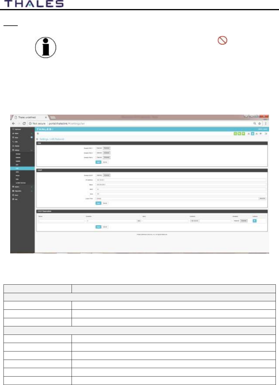
LAN
NOTE
This is an ADMIN functional only. If the user sees this icon,
login as the ADMIN to continue. Otherwise this is a view only
screen.
The LAN page, shown in Figure 4-25, allows PoE to be enabled or disabled on the three LAN
ports and DHCP to be enabled and configured or disabled. Each LAN port PoE is Class 2 and
capable of providing up to 6.5 watts of power to the connected device. See Table 4-7 for more
information on the information that is entered.
Figure 4-25 Settings
LAN Screen
Table 4-7 Settings
LAN
Section
Value
PoE
Enable PoE 1
Disabled / Enabled (Enabled is the default setting)
Enable PoE 2
Disabled / Enabled (Enabled is the default setting)
Enable PoE 3
Disabled / Enabled (Enabled is the default setting)
DHCP
Enable DHCP
Disabled / Enabled (Enabled is the default setting)
IP Address
Enter the IP Address
Mask
Enter the Mask Number
Start
Enter the starting value for the octet
End
Enter the ending value for the octet
Lease Time
Enter the Lease Time being allotted (in seconds)
4-26
User Manual PN 84468 Rev 1
Section
Value
DHCP Reservations
Name
Enter the name of the DHCP Reservation
Duration
Enter the length of time (in seconds)
MAC
Enter the MAC address
Address
Enter the last digits of the IP Address
Enabled/Disabled
Disabled / Enabled (Enabled is the default setting)
WAN
NOTE
This is an ADMIN function only. If the user sees this icon,
login as the ADMIN to continue. Otherwise this is a view only
screen.
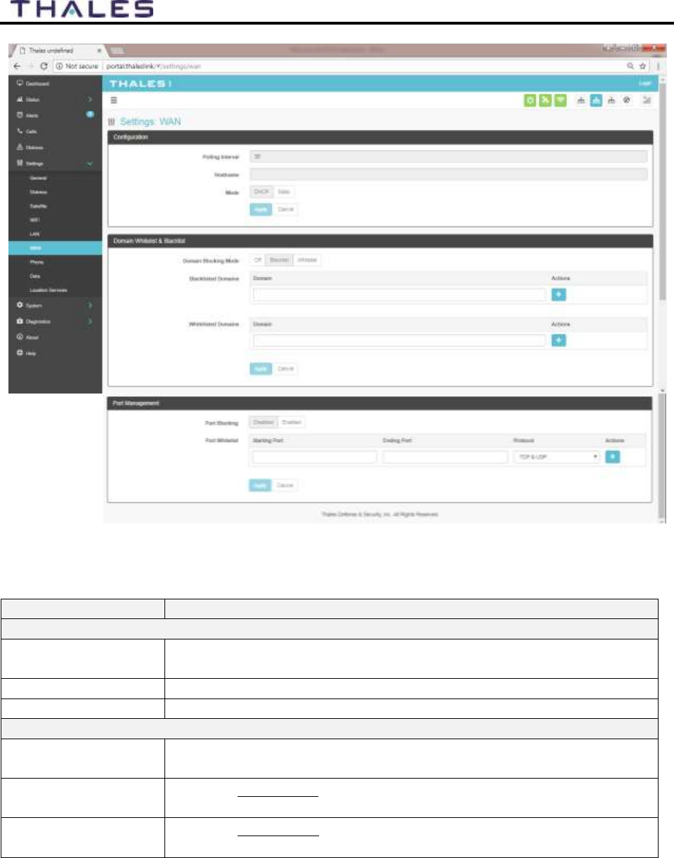
The WAN page, shown in Figure 4-25, allows configuration of the WAN data service. The
settings include configuring whitelists and blacklists for domains, configuring port blocking and
port whitelists.
When adding a Domain to a Black/Whitelist it is always necessary to first select the button
BEFORE selecting the button. After selecting the button, the domain can always be
edited or deleted using the buttons BEFORE selecting the button to save. If
the button is not selected before leaving the WAN menu item, the data will not be saved.
Additional details about these settings are described in Table 4-8.
4-27
User Manual PN 84468 Rev 1
Figure 4-26 Settings
WAN Screen
Table 4-8 Settings
WAN
Section
Value
Configuration Management
Polling Interval
Enter the desired polling interval for checking network status.
(Acceptable values are 1 to 60000 milliseconds).
Hostname
Enter the Hostname
Mode
DHCP or STATIC (DHCP is the default setting)
Domain Whitelist & Black List
Domain Blocking
Mode
OFF / Blacklist / Whitelist (OFF is the default setting)
Blacklisting
Enabling allows ALL websites EXCEPT those listed (very little
restriction)
Whitelisting
Enabling blocks ALL websites EXCEPT those listed (the most
restriction)
4-28
User Manual PN 84468 Rev 1
Section
Value
Port Management
Port Blocking
Disabled / Enabled (Disabled is the default setting)
Port Whitelist
Enter the Starting Port and Ending Port number.
Select the applicable protocol (TCP & UDP or TCP only or UDP
only) (TCP & UDP is the default setting)
Phone
NOTE
This is an ADMIN functional only. If the user sees this icon,
login as the ADMIN to continue. Otherwise this is a view only
screen.
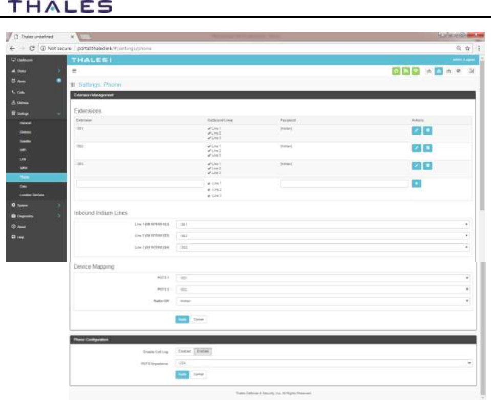
The Phone Settings page, shown in Figure 4-27, allows configuration of phone extensions and
mapping of those extensions to the outbound Iridium phone lines as well as which extension
rings for each inbound Iridium line. There are three (3) high quality Iridium phone lines. Each
extension can be mapped to one, two, three or none of the Iridium phone lines for outbound calls
by checking the box next to the corresponding Line in the Outbound Lines column. By selecting
the “pencil” icon, a password can be entered for each extension if desired. An extension can be
deleted by selecting the “trashcan” icon. All changes are saved only after the APPLY button is
selected.
Each of the three Iridium phone lines (Inbound) can be mapped to ring only one extension. The
extension is selected from the pull-down menu. Configuration of analog devices such as the
POTS phones and the Radio Gateway are configured on this page. Each of these devices can be
mapped to an extension.
Finally, in the Phone Configuration area, call logs can be enabled or disabled and the POTS
phone impedance can be selected for optimal performance.
When adding an extension, it is always necessary to first select the button BEFORE
selecting the button. Several extensions can be added by selecting the button
multiple times, and then selecting the button. After selecting the button, the
extension can always be edited or deleted selecting the buttons BEFORE selecting the
button to save. If the button is not selected before leaving the Phone menu item,
the data will not be saved.
Table 4-9 describes the settings in more detail.
4-29
User Manual PN 84468 Rev 1
Figure 4-27 Settings
Phone Screen
4-30
User Manual PN 84468 Rev 1
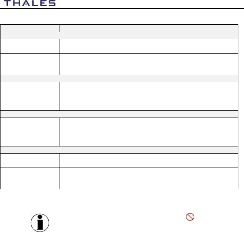
Table 4-9 Settings
Phone
Section
Value
Extension Mapping
1-88888
Phone extensions are set up here and mapped to out bound Iridium
phone lines. Extension numbers cannot begin with 0 or 9.
1001-1003
Default extensions that map to the three Iridium phone lines. The
default has each extension mapping to all three outbound Iridium
lines.
Inbound Iridium Lines
1-88888
Maps each inbound Iridium line to a single extension previously set
up.
1001 - 1003
Default extensions 1001, 1002 and 1003 are mapped to Line 1, Line 2
and Line 3 respectively
Device Mapping
POTS
Assigns extensions to POTS 1 and POTS 2 phones
(Note: 2 POTS phones can be attached with a splitter to the POTS
connector.
Radio GW
Assigns extension to the Radio Gateway
Phone Configuration
Enable Call Log
Disabled / Enabled (Enabled is the default setting). Call logs display
Active Calls and Call History when the Calls menu item is selected.
POTS Impedance
Sets the dynamic output of the POTS system to match regional Phone
types (USA, Australia, Europe, UK, USA-Loaded) (USA is the
default setting)
Data
NOTE
This is an ADMIN function only. If the user sees this icon,
login as the ADMIN to continue. Otherwise this is a view only
screen.
From the Data page, shown in Figure 4-28, data is enabled or disabled and the routing is
configured. The data can be configured to always go through the Iridium satellite system, always
go through the WAN port or go through both, depending on availability of the WAN network.
For the automatic data routing feature, the WAN network takes precedence over the
Iridium satellite network.
When the Data Route is set to ANY, and with a WAN device attached (i.e. cellular
modem), the system automatically switches to the WAN attached network when signal is
available. The system will ping the internet to determine if the WAN device is in range, and
if so switches the data path from Satellite to WAN. If the signal drops out, the data path
switches back to Satellite.
Selecting ANY will cause all data to go through the Iridium satellite network if no WAN
device is attached or if the WAN device is not powered.
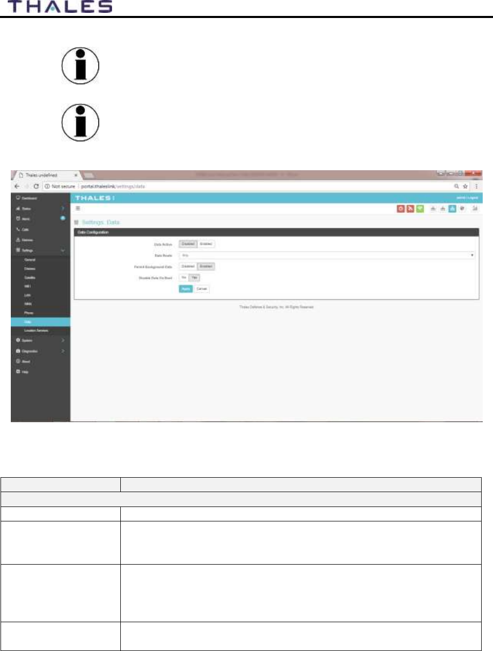
4-31
User Manual PN 84468 Rev 1
NOTE
The WAN port does not have Power of Ethernet (PoE)
capability, so any device plugged into the WAN port needs to
provide its own power source. The TU does not provide power.
NOTE
The automatic data routing feature does not apply to voice calls.
All voice calls are routed through the Iridium satellite system
100% of the time. The WAN port is only for data.
Figure 4-28 Settings
Data Screen
Table 4-10 Settings
Data
Section
Value
Data Configuration
Data Active
Disabled / Enabled (Disabled is the default setting)
Data Route
Select the desired data route (Any, Satellite, or WAN Port) (Any is the
default setting). The automatic data routing feature requires Any be
set.
Permit Background
Data
Disabled / Enabled (Enabled is the default setting). If Enabled, this
setting allows for GPS location information to be transmitted even
when data is disabled. This is valuable if location services are being
used.
Disable Data on Boot
NO / YES (NO is the default setting). Determines the default data
operations state when the system is restarted.
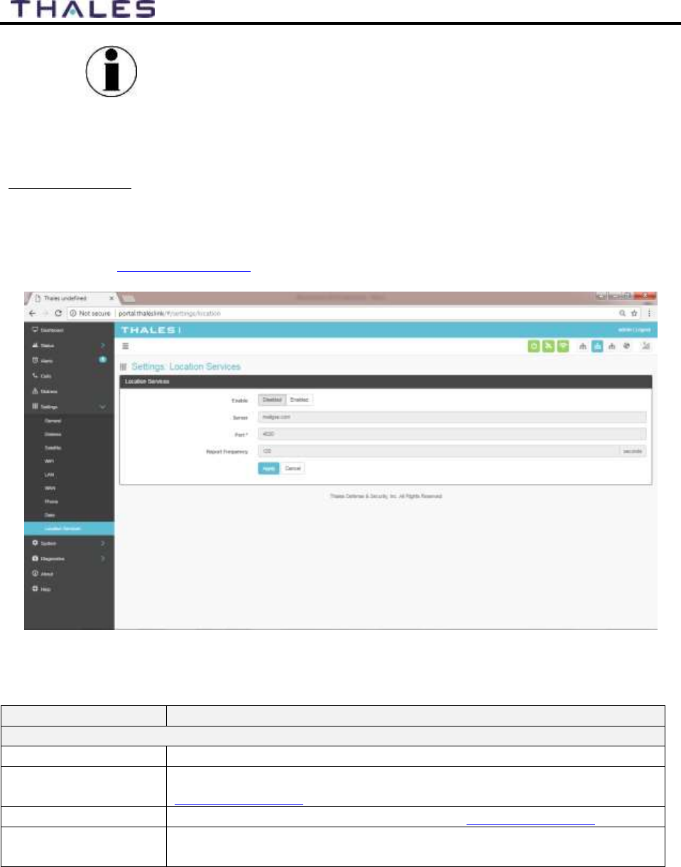
4-32
User Manual PN 84468 Rev 1
NOTE
Since the system default for “Satellite Data Sessions” is OFF,
the “Disable Data on Boot” configuration has been added so that
when the system is turned off and on frequently, it comes up in a
known state each time for data. This allows the unit to start up
with data sessions turned on each time or to be off.
Location Services
From the Location Services page, shown in Figure 4-29, Location Services are enabled and
disabled and the settings are configured (when enabled). Thales offers ClearSIGHT as the
preferred tracking service. This requires an account and service subscription. More information
can be found at www.clrSight.com.
Figure 4-29 Settings
Location Services Screen
Table 4-11 Settings
Location Services
Section
Value
Data Configuration
Enable
Disabled / Enabled (Disabled is the default setting)
Server
Enter the name of server. Get this information from
www.clrSight.com
Port
Enter the port number of the service from www.clrSight.com
Report Frequency
Default setting is 120 seconds. When DISTRESS is set to enabled,
frequency will be every 5 minutes.
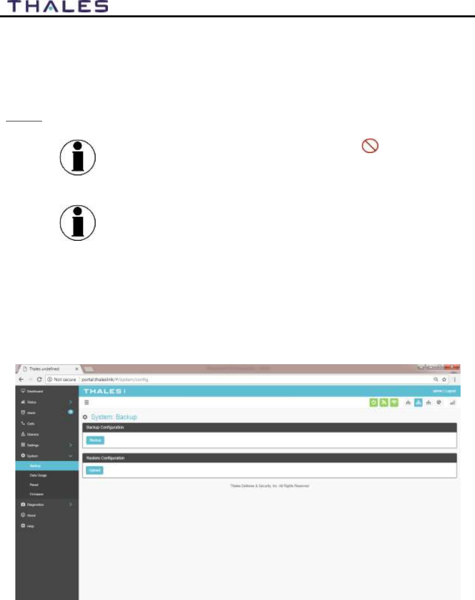
4-33
User Manual PN 84468 Rev 1
System
The System menu item allows for backing up a configuration and restoring it, monitoring of
system data usage (estimate for informational purposes only), performing a system reboot,
restoring factory default settings, and provides information on the system firmware versions.
Backup
NOTE
This is an ADMIN function only. If the user sees this icon,
login as the ADMIN to continue. Otherwise this is a view only
screen.
NOTE
File download cannot be done on a phone or tablet using iOS
operating system. If a configuration file needs to be saved, use a
device with a browser other than iOS.
Refer to Figure 4-30. Before performing a firmware update, replace a TU, cloning information
for multiple systems or just as good practice periodically, the system configuration file should be
backed up to prevent loss of custom configuration settings in the event that an issue should
occur. Backup can occur on devices that have a file system where the configuration file can be
downloaded and saved (personal computer, laptop, Android). Backing up the current
configuration is a simple process detailed below.
Figure 4-30 System
Backup Screen
4-34
User Manual PN 84468 Rev 1
Backup Configuration
o Connect a computer to the TU either through Ethernet or Wi-Fi
o Select BACKUP, will automatically backup the data contained in the
Management Portal.
o The backup file can be renamed as long as the file extension is “.json”
NOTE: This is very useful for restoring setting to a replacement unit or cloning
setup for multi-unit fleet service
Restore Configuration
o In the event the configuration file needs to be reloaded, RESTORE
CONFIGURATION will enable you to reload a previous saved configuration file.
o Select RESTORE CONFIGURATION
o Navigate to the file that was saved.
o Open the file to Upload
Data Usage
NOTE
This is an ADMIN functional only. If the user sees this icon,
login as the ADMIN to continue. Otherwise this is a view only
screen.
Refer to Figure 4-31. Data usage is shown for information purposes only. If there is a data limit
set, this information will be provided on this screen. The system data usage can be reset to
restart the data count. Select RESET and then YES, RESET to confirm. Otherwise, select NO,
CANCEL (Figure 4-32). For Satellite Data Limits – pressing the VIEW SATELLITE LIMITS
button, will bring up the SETTINGS SATELLITE Screen (Figure 4-23).
NOTE
This is an estimate of data used and does not accurately
represent the billable data total. It also does not limit or restrict
data usage even if the Data Usage exceeds the Data Cap. To get
accurate data usage, please contact your service provider.
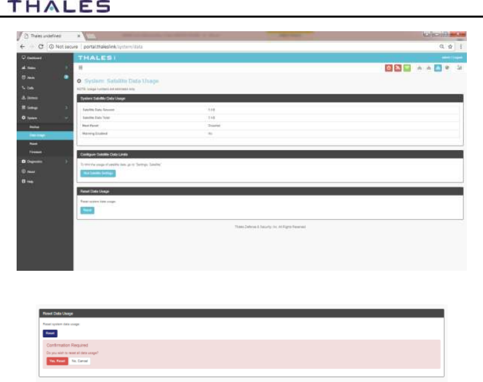
4-35
User Manual PN 84468 Rev 1
Figure 4-31 System
Data Usage Screen
Figure 4-32 Reset Data Usage Screen
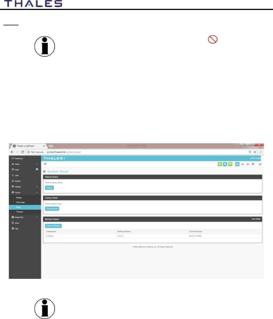
4-36
User Manual PN 84468 Rev 1
Reset
NOTE
This is an ADMIN function only. If the user sees this icon,
login as the ADMIN to continue. Otherwise this is a view only
screen.
Refer to Figure 4-33. In the event the system is not responding correctly, a system reboot can be
performed. Select REBOOT to restart the system.
If there is a larger issue such as a corruption or if configuration settings have made the system
non-operational, a Factory Reset can be performed. Select FACTORY RESET. This resets all
the configuration settings to the default settings.
Backup Version will revert the system to the previous software version.
Figure 4-33 System
RESET
NOTE
Factory Rest will restore factory defaults and all users’
customized settings will be lost.
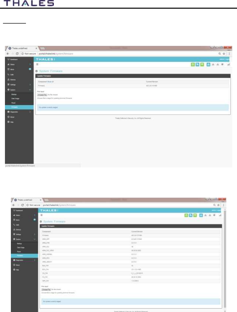
4-37
User Manual PN 84468 Rev 1
Firmware
Refer to Figure 4-34. The Firmware page displays the current firmware version numbers. These
may be helpful if customer service is contacted to resolve an issue.
Figure 4-34 System
Firmware Screen
Selecting the SHOW ALL will display system level information (Figure 4-35).
Figure 4-35 Firmware Screen – Show All
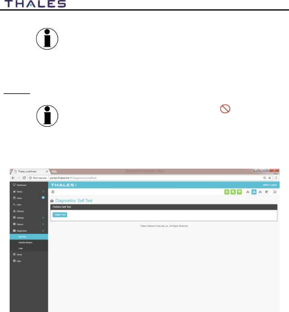
4-38
User Manual PN 84468 Rev 1
NOTE
For detailed instructions on updating Firmware on the TU please
reference chapter 5 of this manual.
Diagnostics
Self-Test
NOTE
This is an ADMIN function only. If the user sees this icon,
login as the ADMIN to continue. Otherwise this is a view only
screen.
The Self-Test diagnostics page (Figure 4-36), users will be able to run a diagnostic test of the
system and results will be available in the diagnostic logs page for debug.
Figure 4-36 Diagnostics
Self-Test Screen
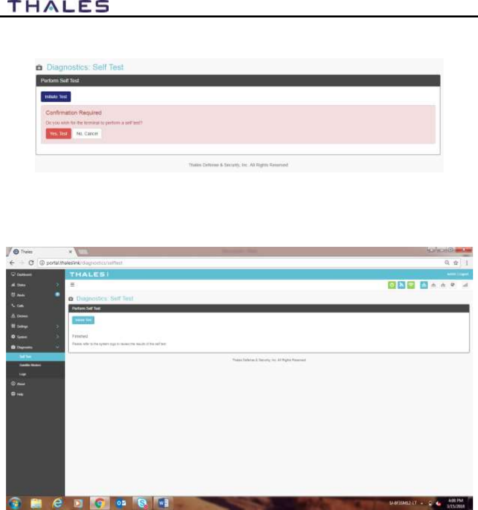
4-39
User Manual PN 84468 Rev 1
Refer to Figure 4-37. Select INITIATE TEST and then confirm by selecting YES, TEST to
perform the self-diagnostics test.
Figure 4-37 Perform Self-Test Confirmation
Once the Self-Test is complete, you will be directed to refer to the system logs (Figure 4-40) for
results of the test (Figure 4-38).
Figure 4-38 Perform Self Test Completed Screen

4-40
User Manual PN 84468 Rev 1
Satellite Modem
NOTE
This is a view only page.
The Satellite Modem diagnostics page provides information that will aide in the debugging of the
system.
The Satellite Modem page is divided into the following sections as shown in Figure 4-37:
System Status
Constellation Status
Static Config
System Diagnostics
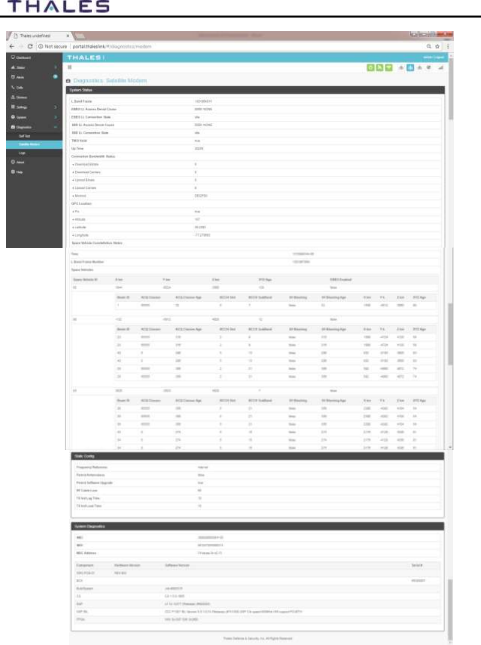
4-41
User Manual PN 84468 Rev 1
Figure 4-39 Diagnostics
Satellite Modem Screen
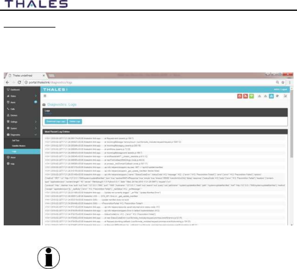
4-42
User Manual PN 84468 Rev 1
Diagnostics Logs
Refer to Figure 4-40. The Diagnostics Logs provide the operator with the results of all recent
diagnostic tests. This information can be used in debugging / troubleshooting the system. A
limited number of logs can be viewed on the screen or detailed logs can be downloaded by
selecting DOWNLOAD LOGS. Logs can be erased by selecting DELETE LOGS.
Figure 4-40 Diagnostics
Logs Screen
NOTE
The “Most Recent Log Entries” only shows the last 100 log
entries. For additional information, select DOWNLOAD LOGS
(.tgz) for additional information.
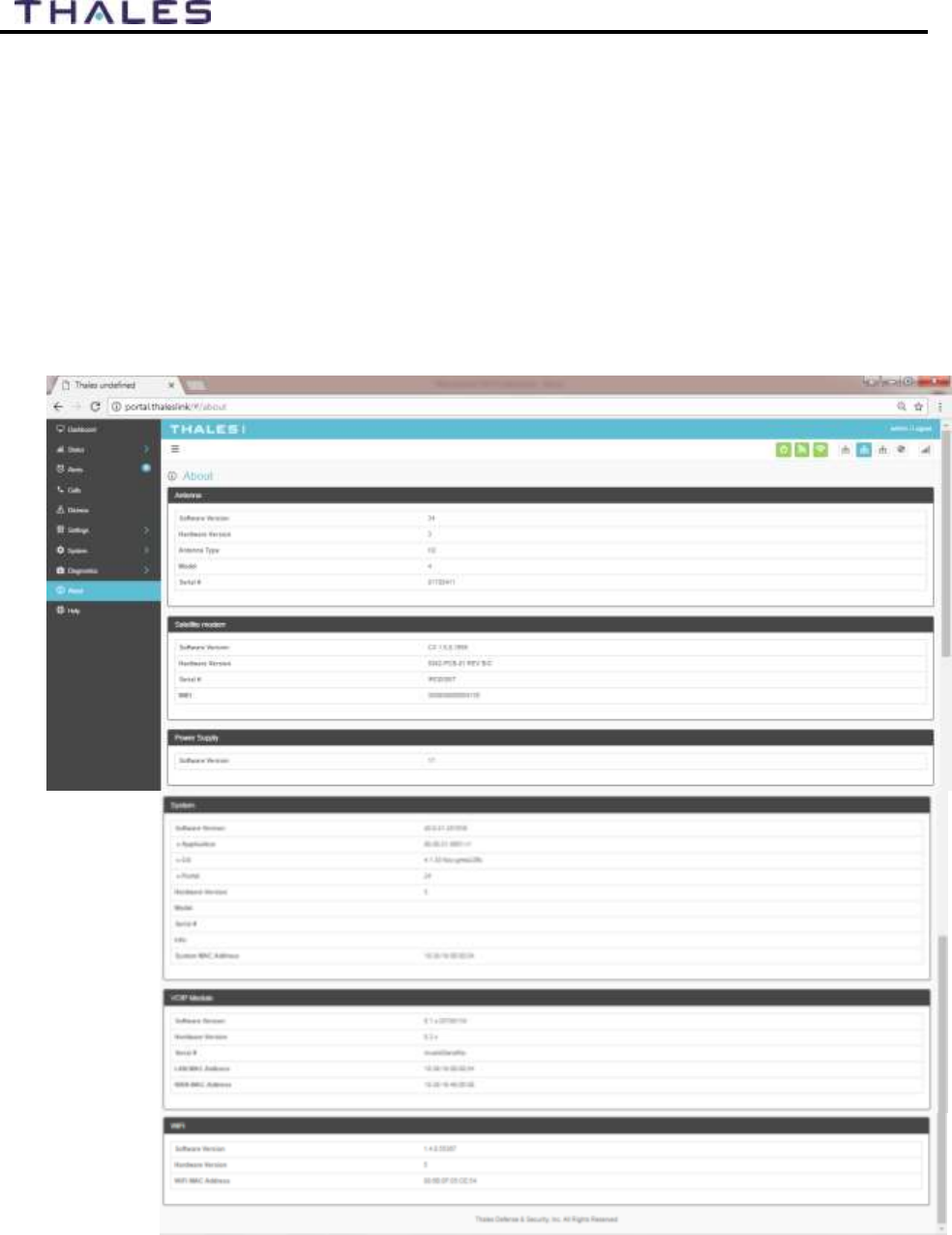
4-43
User Manual PN 84468 Rev 1
About
Refer to Figure 4-41. This page provides detailed information relating to the equipment,
including unique HW information and its current software version.
This includes,
Antenna
Satellite Modem
Power Supply
System
VOIP Module
Wi-Fi
Figure 4-41 About Screen
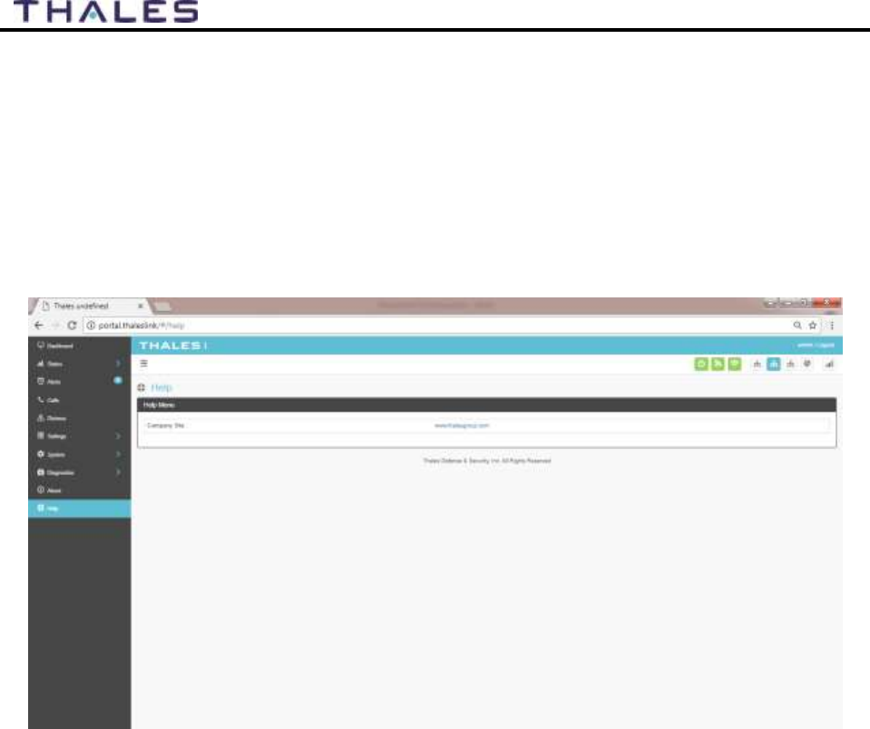

5-1
User Manual PN 84468 Rev 1
FIRMWARE UPGRADE CHAPTER 5
On occasion it may be necessary to update MissionLINK software to add features or fix issues
found in the software. This section will step through the process of those updates. The firmware
file will contain updates for both the TU and the antenna if needed, so a single load automatically
updates both. It is important to make sure the system is connected, powered up, and operational
before attempting a firmware update. Do not remove power from the TU or remove the
antenna connection while an update is in process. This may cause a corruption to occur and
force a revert to the previous software version.
NOTE
For SW reset or returning to factory defaults please refer to
Chapter 6 RESETS.
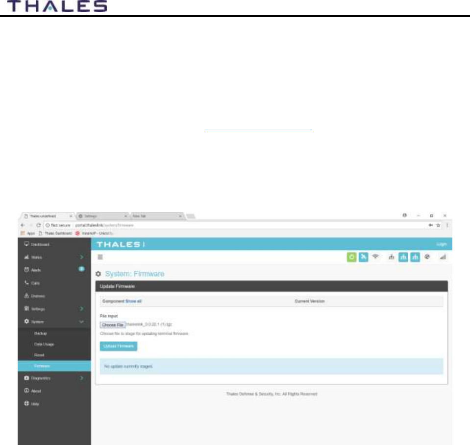
5-2
User Manual PN 84468 Rev 1
INSTALLING THE FIRMWARE ON MISSIONLINK
Via Computer or Mobile device.
1. With PC or Mobile Device connect to “THALESLINK” on Wi-Fi or via Ethernet
(RJ-45) port.
2. Open a web browser and type: http://portal.thaleslink (do not type .com or any other
extension)
3. Once prompted enter Username and Password.
4. Navigate to the SYSTEM Firmware (Figure 5-1)
Figure 5-1 System
Firmware
5. Select CHOOSE FILE.
6. Go to File Input and select the Browse button.
7. Navigate to location of downloaded file (See Page Error! Bookmark not defined.).
This file should have the firmware version and .tgz” as the file extension
o Example: thaleslink_0.0.22.1.tgz
8. Select the “SELECT” button
9. After file has been selected return to the Firmware page.
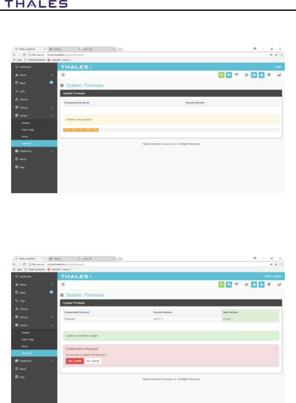
5-3
User Manual PN 84468 Rev 1
10. Select “UPLOAD FIRMWARE” button. This may take a few seconds as a progress
bar moves across the page (see Figure 5-2).
Figure 5-2 Firmware Being Staged
11. Once staged the Firmware page will display “UPDATE STAGED” (At this point user
will be able to see Current and New Versions side by side on the Firmware page)
12. Select “ RUN”
Figure 5-3 System
Firmware Update Confirm
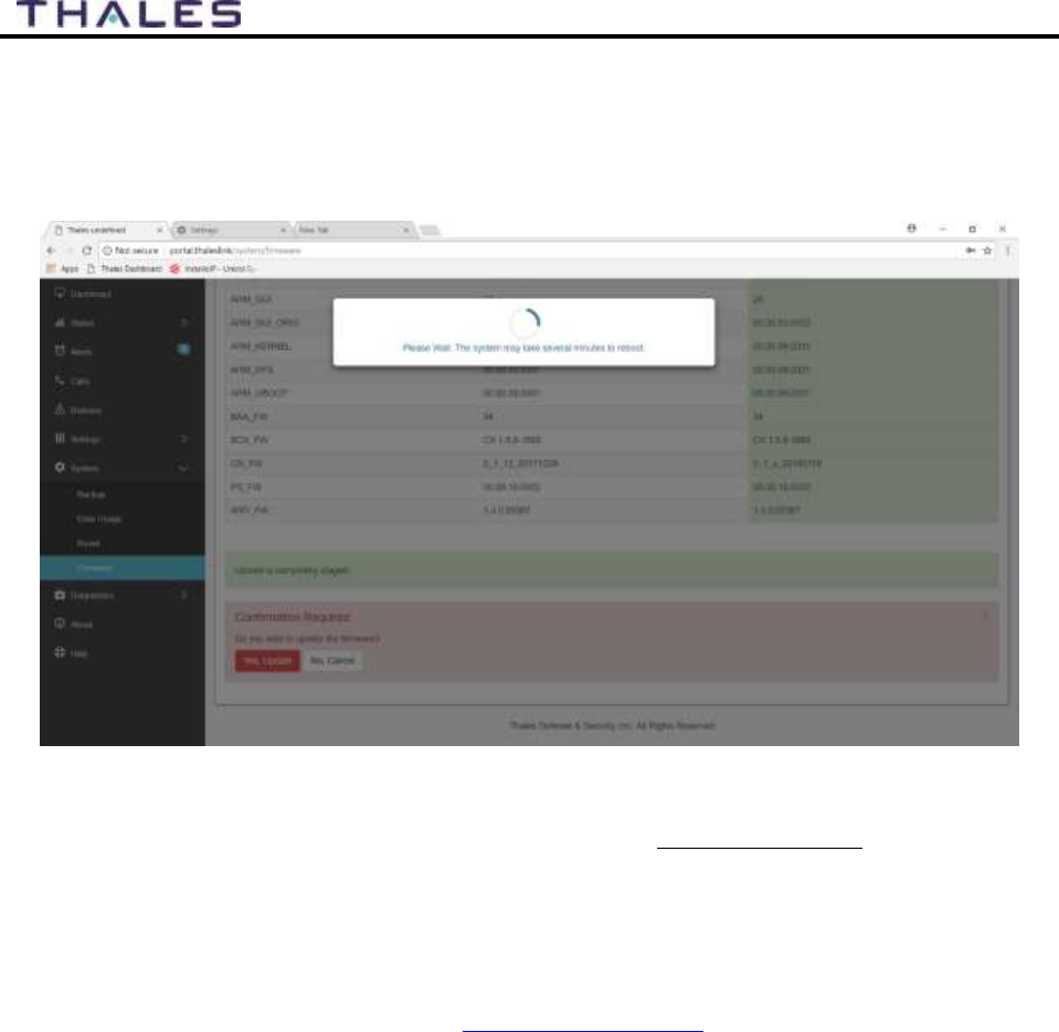
5-4
User Manual PN 84468 Rev 1
13. Once YES, UPDATE is selected, the process to Update Firmware has begun and will
take approximately 10 to 15 minutes to complete. *DO NOT REMOVE POWER
DURING THIS PHASE*
Figure 5-4 Firmware Update in Process
14. Once completed and the system reboots, wait for all the Status LEDs to go Solid
Green and/or Blue. This may take a couple minutes.
15. Verify Firmware Update by connecting to “THALESLINK” (or SSID set in
MissionLINK) on Wi-Fi or Ethernet port.
16. Open a web browser and type: http://portal.thaleslink (do not type .com or any other
extension).
17. Once prompted enter the admin Password (this will not change from before the
firmware update).
18. Navigate to the SYSTEM Firmware to view updates. (Software version can also be
found in the ABOUT menu item.)
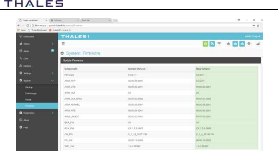
5-5
User Manual PN 84468 Rev 1
Figure 5-5 System
Firmware Update Completed
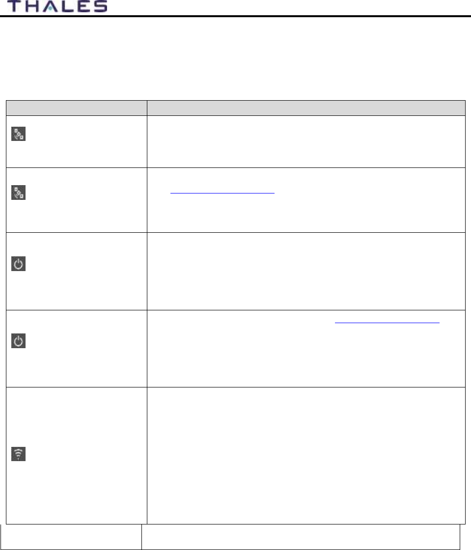
6-1
User Manual PN 84468 Rev 1
TROUBLESHOOTING CHAPTER 6
TROUBLESHOOTING
Table 6-1 Troubleshooting
PROBLEM
SOLUTION
Satellite LED Flashing
GREEN
Flashing GREEN light indicates that it is acquiring the satellite. If
it continues to flash for more than 5 minutes, check that the
antenna has a clear view of the sky.
Reboot TU.
Satellite LED Flashing
RED
Critical Fault Detected. Open Management Portal
http://portal.thaleslink and check Alerts. Make any adjustments.
(For example: check antenna connection, or GPS not acquired.)
Turn unit off and on again. If same result, contact your service
provider.
System LED Flashing
Green
Start-up in progress. Wait until unit has run diagnostics and
completed start procedure. This may take more time than usual
when acquiring satellites for the first time
Switch power off and back on if the light doesn’t turn solid green
after 5 minutes.
System LED Flashing
RED
Fault Detected. Open Management Portal http://portal.thaleslink and
check for alerts. Make any adjustments. (For example: Common alerts
include, but not limited to, are the SIM Card not installed, SIM Card
not provisioned. Power-Up Test (POST) failure.)
Turn unit off and on again. If same result, contact your service
provider.
Wi-Fi LED
OFF – Turn Wi-Fi ON using the Management Portal through a
hardwired, PoE connection.
THALESLINK > SETTINGS > WIFI
Solid RED – Wi-Fi may need to turned off and back on again from the
Management Portal. If the LED does not turn to GREEN within a
minute, reboot the TU.
Flashing GREEN – If this continues for more than a minute or two,
check for NO OR WEAK Wi-Fi
Call Logs are not appearing
Call logs must be enabled. Verify call logs are enabled (SETTING
PHONE PHONE CONFIGURATION)
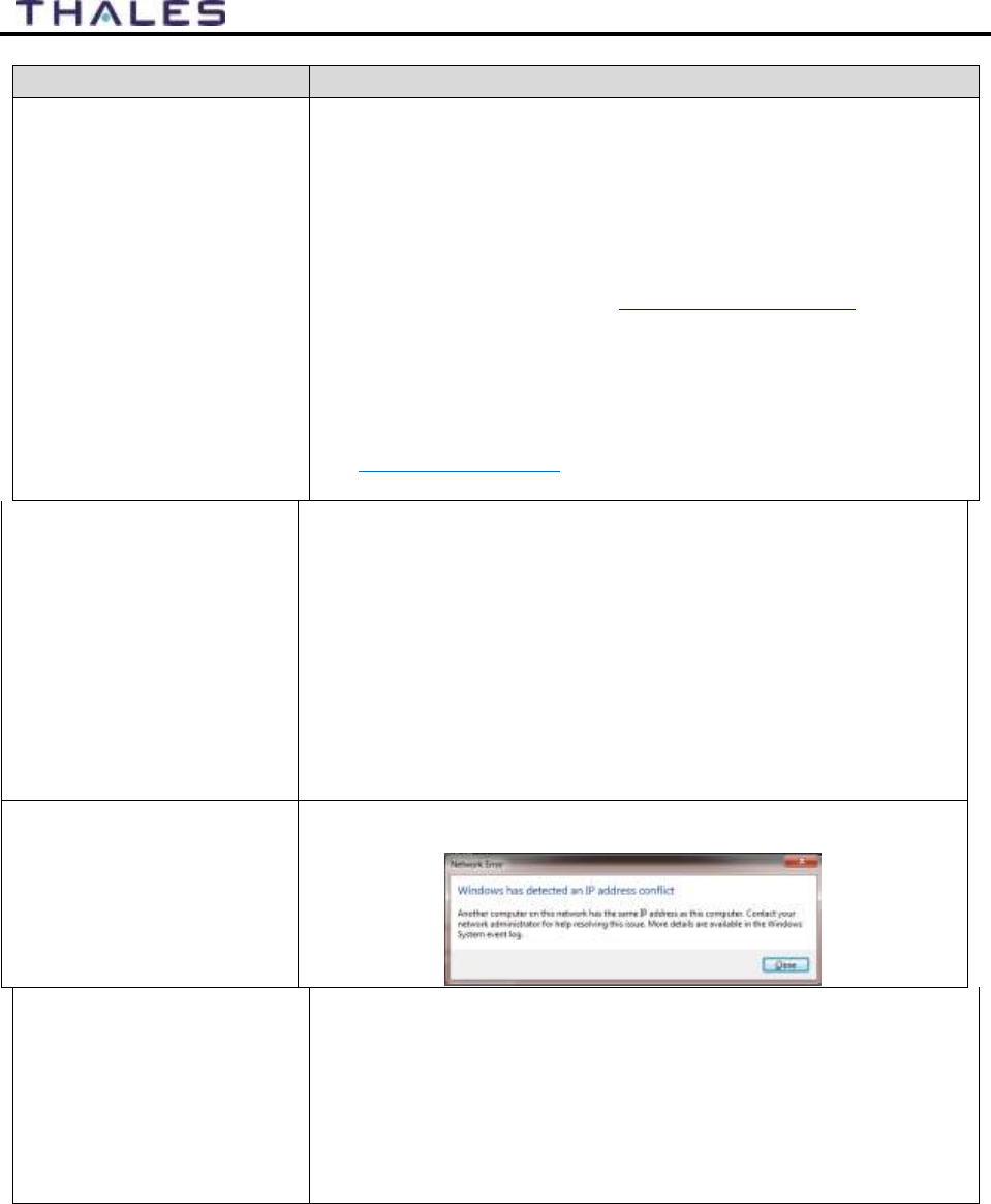
6-2
User Manual PN 84468 Rev 1
PROBLEM
SOLUTION
Cannot connect to the
Management Portal
Ensure Terminal Unit is powered ON
Ensure Wi-Fi is enabled and connected to ThalesLINK (or
renamed SSID). If using a Wi-Fi enabled device, the Wi-Fi LED
on the TU should be solid GREEN. If not using Wi-Fi, ensure Cat
5 cable is connected to one of the three Ethernet ports (NOT WAN
or POTS Port). If Ethernet connection, replace the cable and re-
check connection
Open web browser and type http://portal.thaleslink/#. Ensure
network settings are correct on the connected device.
Device’s browser may be incompatible. Update or try different
browser.
You may need to reconnect via Ethernet or Wi-Fi to the TU.
Check to make sure the correct address is typed in
http://portal.thaleslink
Cannot connect to Wi-Fi
service
Check that the Wi-Fi antenna is attached and tightly screwed in.
Check that the TU’s Wi-Fi LED is solid GREEN.
Check to see if there’s an available connection by checking the
devices that are connected in Status Current Devices page.
Only 5 simultaneous devices can connect to the Wi-Fi. Any
additional connection attempts are blocked.
Remove one or more devices from the Wi-Fi and try again to
connect.
Use the Wi-Fi Device Whitelist to limit access to specific wireless
devices.
Network Error
If you receive a message similar to this, another user is attempting to
use the same IP Address as your computer.
No or Weak Wi-Fi Signal
Connect Wi-Fi antenna and ensure it is secured tightly
If walls or metal obstructions are between the TU and the Wi-Fi
device, move closer to the TU or move the TU to a better location
with less obstructions
Check to make sure Wi-Fi device is connected to the TU’s Wi-Fi
and verify that you are connected to the ThalesLINK.
Check the Management Portal to make sure the Wi-Fi device is
registered as a user.

6-3
User Manual PN 84468 Rev 1
PROBLEM
SOLUTION
ThalesLINK is not obtaining
a satellite signal (Satellite
LED is red)
Check signal bars at the top of the Management Portal. If no bars
are highlighted, the satellite is not being detected. Wait a few
minutes to see if the signal strength improves as another satellite
comes into view.
Check antenna connection at the TU and antenna. Make sure no
corrosion has occurred on the cable connections to the antenna and
that the connectors are screwed in tightly.
Check antenna for a clear view of the sky with no obstructions.
Relocate antenna if needed.
Check for interferers in the area that could be affecting the signal
such as active radars, VSAT systems and other radio antennas.
Turn those off and retest.
Move vessel to a new location and retest if other interfering
vessels are in the area
Reboot TU and check the Alerts.
Call Service Provider if the satellite connection is still not
working.
Terminal Unit does not
Power-ON
Check TU for Green lights, If green light is on Unit has Power
Push power button on front of TU.
Check that the power source is providing 10-32V and is not
current limited.
Check connection of the 10-32V DC cable has correct polarity.
Check to ensure Ignition line is connected to switched line or
connected to Red (Positive line) for continuous operation.
Check that ignition or remote switch is turned on if ignition line is
connected.
If using AC/DC converter (optional), make sure the AC outlet has
power and that the plug is securely in the AC outlet and the other
end is securely connected to the TU.
Terminal Unit has power but
accessories not working
Remove power from accessories and disconnect from TU. Restart
TU using the power button or remove power from TU for 10
seconds. After TU has rebooted re-attach accessories
If PoE accessory not receiving power, make sure PoE is enabled
for that port.
PoE is not available on WAN port. Any device on WAN port
needs its own power source.
Check VoIP phone manuals for proper configuration. Each phone
may have a different configuration method.

6-4
User Manual PN 84468 Rev 1
PROBLEM
SOLUTION
Terminal Unit is not
responding
Check LED status on TU or on Management Portal. Make sure
there are no RED LEDs. Check for Alerts in Management Portal
by selecting the Alerts menu item
Reboot the system and recheck for any Alerts that have been
generated.
Call Service Provider if the TU is still not responding.
As a last resort, use the manual reset button, located below Wi-Fi
antenna port, using a straightened paper clip or similar sized article
insert into port and push reset button.
NOTE: This is not recommended as a routine troubleshooting
measure. All user data and debug information will be lost and
factory defaults returned.
Terminal Unit not connecting
to Management Portal
System LED is flashing GREEN, wait until it turns solid GREEN,
then try reconnecting to the portal.
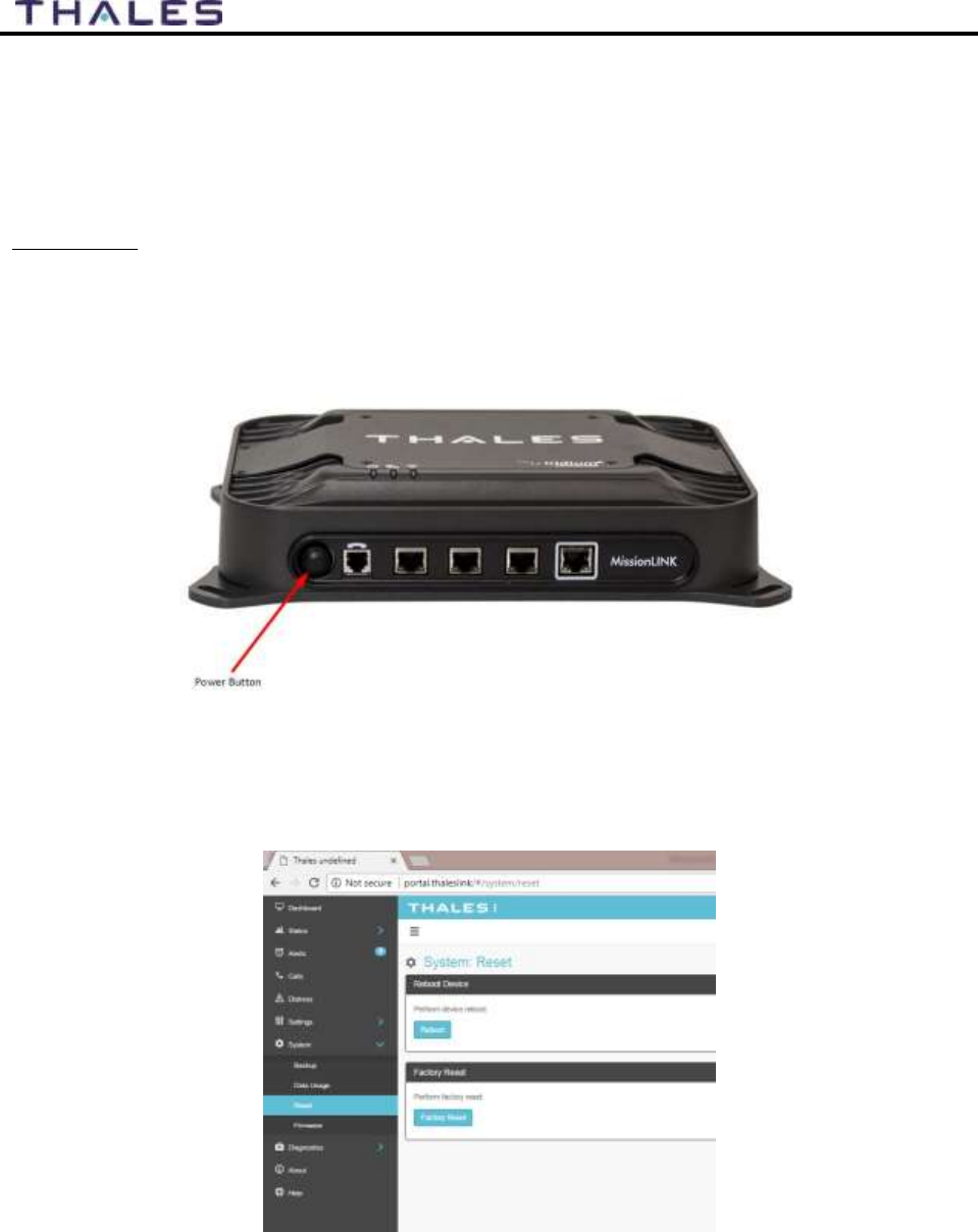
6-5
User Manual PN 84468 Rev 1
System Resets
In a rare situation where the MissionLINK system is not responding or operating properly, it may
be necessary to reset the system. There are varying levels of system resets that are explained
below:
Power Cycle
There are three (3) ways to power cycle the system:
If power is already on (LEDs are illuminated), press and release the Power Button on the
unit to power the unit off. Again, press and release the Power Button to power the unit
on. It will take a couple minutes before the boot-up cycle completes.
Figure 6-1 Location of Power Button on Terminal Unit (TU)
From the Management Portal, select SYSTEM RESET REBOOT DEVICE. Press
REBOOT. It will take a couple minutes before the boot-up cycle completes.
Figure 6-2 Management Portal - SYSTEM
RESET
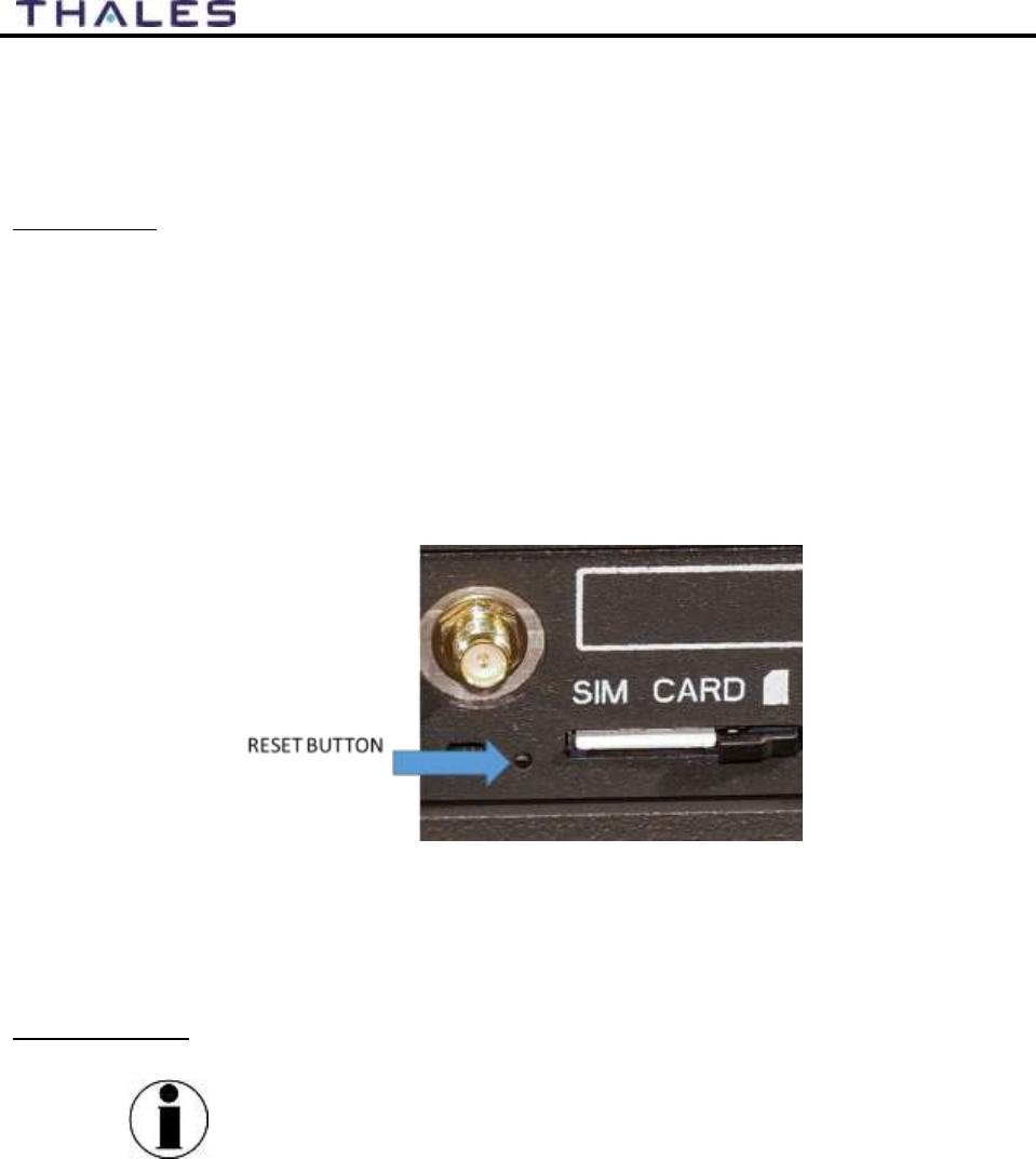
6-6
User Manual PN 84468 Rev 1
If neither of these work, then unplugging the system from the power source may be
necessary. Note: Always wait at least 20 seconds for power inside the unit to dissipate
before reconnecting the input power.
Factory Reset
As its name implies, this restores the factory defaults (passwords will return to “admin”). This is
particularly helpful when a system has been wrongly configured and starting over is the easiest
option. If an admin password is customized and is forgotten, the only way to reset it is to use the
factory reset option.
Factory Reset can be accomplished by either of these two actions:
Remove the SIM card cover exposing the reset hole. Using a straightened paperclip,
insert it into the round hole just to left of the SIM card as shown in Figure 6-3. Push in
until the paperclip causes the switch to click. A factory reset will occur.
Figure 6-3 RESET BUTTON
From the Management Portal select SYSTEM RESET FACTORY RESET.
Confirm by selecting YES, FACTORY RESET. A factory reset will occur.
Firmware Revert
NOTE
FIRMWARE REVERT should only be used when a system has
a serious issue and all other troubleshooting tips have been tried.
Call your Service Provider before doing a firmware revert to
make sure all other troubleshooting steps have been exhausted.
This restores the previous version FIRMWARE used on the system.
This can be accomplished by following these steps:
Remove the SIM card cover exposing the reset hole. Using a straightened paperclip,
insert it into the round hole just to left of the SIM card as shown in Figure 6-3.
Push in until the paperclip causes the switch to click. At the same time hold the power
button in until the LEDs blink and then release.

6-7
User Manual PN 84468 Rev 1

6-8
User Manual PN 84468 Rev 1
Alerts
Table 6-2 ALERTS / Error Messages
Alert Name
Description
Level
Additional Information
Corrective Action
ANT_CABLE
Cable loss excessive; check system;
performance maybe degraded.
Critical
Cable loss may exceed the
system spec of 9 dB
Check Antenna cable for
damage or loose
connections. Replace if
necessary.
ANT_MISSING
Unable to detect antenna
Fault
Check Antenna for
damage. Check for loose
connections. Remove and
reinstall the antenna. If
problem continues, replace
antenna.
ANTENNA_POST_FAIL
URE
The antenna has failed POWER ON
SELF TEST
Fault
Check Antenna for
damage. Check for loose
connections. Remove and
reinstall the antenna. If
problem continues, replace
antenna.
BCX-denial
Failed to connect to pass data,
reason – location
Fault
Restart TU. Contact
representative if problem
persists.
BCX_IBIT_FAILURE
The BCX has failed “Initiated Built
In Self-Test” View Logs for details.
Fault
Open
http://portal.thaleslink and
review Self-Test logs.
Restart the Terminal Unit.
If problem persists, contact
representative.

6-9
User Manual PN 84468 Rev 1
Alert Name
Description
Level
Additional Information
Corrective Action
BCX_SIM
Modem failed to read SIM card
Warning
Remove, clean and re-
insert SIM. Contact service
provider if problem
persists.
CN_OFF
CN is powered off, restart required
Critical
CN is noticed to be
unexpectedly off.
Restart TU. Contact
representative if problem
persists.
CN_REBOOT
CN Reboot has occurred, full
system restart is required.
Critical
CN Module restarts while
the system is up and
running.
Restart TU. Contact
representative if problem
persists.
MODEM_ACT
Modem returned an unknown error
– cannot activate
Fault
Restart TU. Contact
representative if problem
persists.
MUX_PLL_UNLOCKED
Antenna mux out-of-lock
Critical
PLL failed to acquire
Restart TU. Contact
representative if problem
persists.
PWR_IBIT_FAILURE
The power has failed “Initiated Built
In Self-Test” View Logs for details.
Fault
Open
http://portal.thaleslink and
review Self-Test logs.
Contact representative.
SIM_MISSING
SIM card not detected
Fault
SIM Card is physically
missing
Replace SIM card

6-10
User Manual PN 84468 Rev 1
THIS PAGE INTENTIONALLY LEFT BLANK
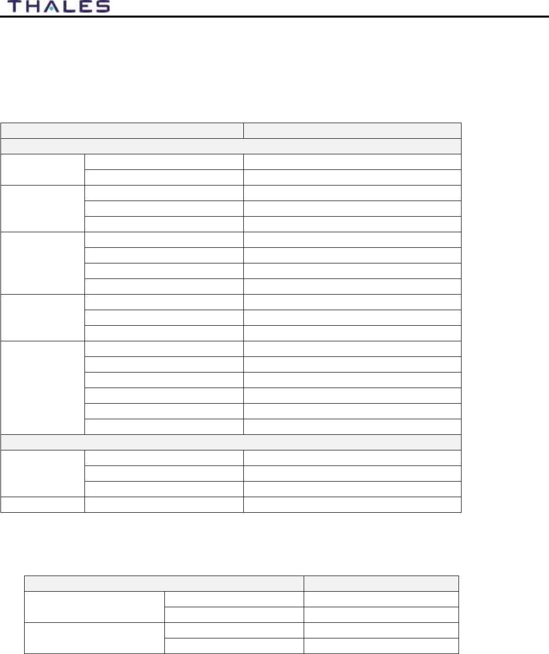
7-1
User Manual PN 84468 Rev 1
TECHNICAL SPECIFICATIONS CHAPTER 7
TECHNICAL SPECIFICATIONS
Table 7-1 Technical Specifications
Description
Parameters
Technical
Frequency of
Operation
Uplink (TX)
1616 to 1626.5 MHz
Downlink (RX)
1616 to 1626.5 MHz
Channelization
FDMA spacing
41.667 KHz
TDMA Timing
8.3 mS Slot in a 90 mS window
Channels Available
240 channels
EIRP
(Weighted
Average)
Voice
9 dBW
Data (Block 1)
11.7 dBW
Data Certus™ 1xC8 16 APSK
15.2 dBW
Data Certus™ 2xC8 16 APSK
18.2 dBW
Modulation
Block 1 Voice/Data
DQPSK
Certus™ C1, C8 Voice/Data
QPSK
Certus™ C8 APSK Data
16 APSK
Antenna
Type
Electronically steered phased array
Polarization
RHCP
Gain
9.5 dBi
Beam Width
31° typical per beam
MissionLINK coverage
8° to 90 elevation
Power
DC Input
Voltage
10-32 VDC
Max Current
12 Amps
Max Power
120 Watts
Ethernet
3x PoE
PSE Class 2 (6.5 Watts each)
TEMPERATURE
Table 7-2 Operating and Storage Temperatures
Description
Temperature Range
Broadband Active
Antenna
Operating Temp
-30°C to +55°C
Storage Temperature
-40°C to +85°C
Terminal Unit
Operating Temp
-30°C to +55°C
Storage Temperature
-40°C to +85°C
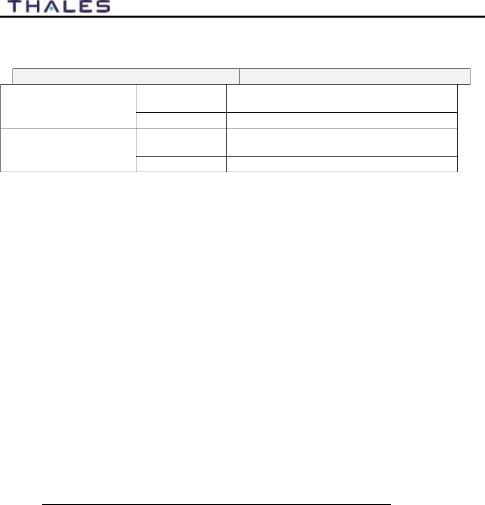
7-2
User Manual PN 84468 Rev 1
PHYSICAL CHARACTERISTICS
Table 7-3 Physical Characteristics
Description
Parameters
Broadband Active
Antenna
Dimensions
14" D x 4" H
(35.6 cm x 10.2 cm)
Weight
7 lbs (3.2 kg)
Terminal Unit
Dimensions
12” L x 9” W x 3” H
(30.5 cm x 23 cm x 7.6 cm)
Weight
< 7.5 lbs (3.4 kg)
CONNECTOR DETAILS:
General Purpose Inputs / Outputs (GPIO)
Refer to Figure 7-2 for the connector and its pinout. The connector is located on the back of the
TU and is labeled I/O. The GPIO has 4 main functions. Some of the functions are reserved for
this connector are not yet implemented (they are reserved for future use.) Refer to Table 7-2 for
the pin descriptions of the GPIO connector.
1. 1-Wire SOS/Distress This distress connection is intended to allow for a remote switch
to activate the distress mainly for situations where the Management Portal or the optional
Thales SureLINK IP Handset is not available. Distress can be activated when Pin 5 has
been connected to GND signal (ANY of the pins, 1, 8, and 12) for more than 3 seconds.
Once set, it sends an automated message stating Distress has been triggered. This
message contains Latitude, Longitude, Altitude and predefined user message (setup in
Management Portal) to a message recipient. (Refer to Page 4-14 for information on how to
create a Distress message.)
IF Location Services are turned on the distress signal will increase frequency of
transmission to every 5 minutes.
NOTE: THERE IS NO EXTERNAL INDICATION OF DISTRESS
This security feature is for user protection. The ONLY way to remove active SOS is to
enter Management Portal under DISTRESS TAB
2. Radio Gateway Advanced users can connect Land Mobile Radio I/O to send and
receive voice and Push-To-Talk (PTT) calls over the MissionLINK. This feature is for
advanced users familiar with Land Mobile Radio systems and requires a custom cable
connections between the GPIO connector (DB-15) and the target Radio (cables not
offered by TDSI). Because each radio system will require a unique setup, it is highly
recommended that you contact your TDSI representative for help in setup of this
advanced user feature. See pinout (Table 7-4) for creating the custom Radio Gateway
cable.
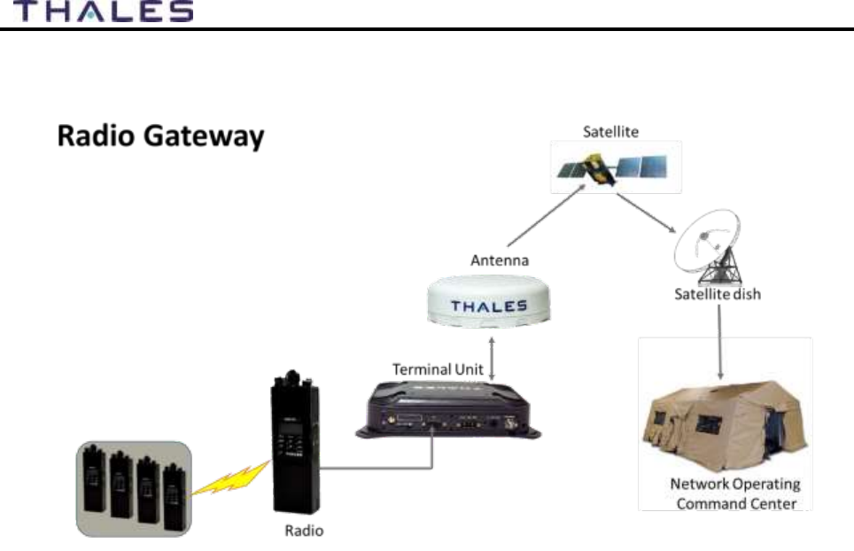
7-3
User Manual PN 84468 Rev 1
Figure 7-1 Radio Gateway for Advanced Land Mobile Services
3. 2- Wire RS232 Reserved for future use.
Contact your service provider or Thales Customer Service for help in setting up of this
advanced user feature.
4. User defined GPIO Reserved for future use.
Contact your service provider or Thales Customer Service for help in setting up of this
advanced user feature.
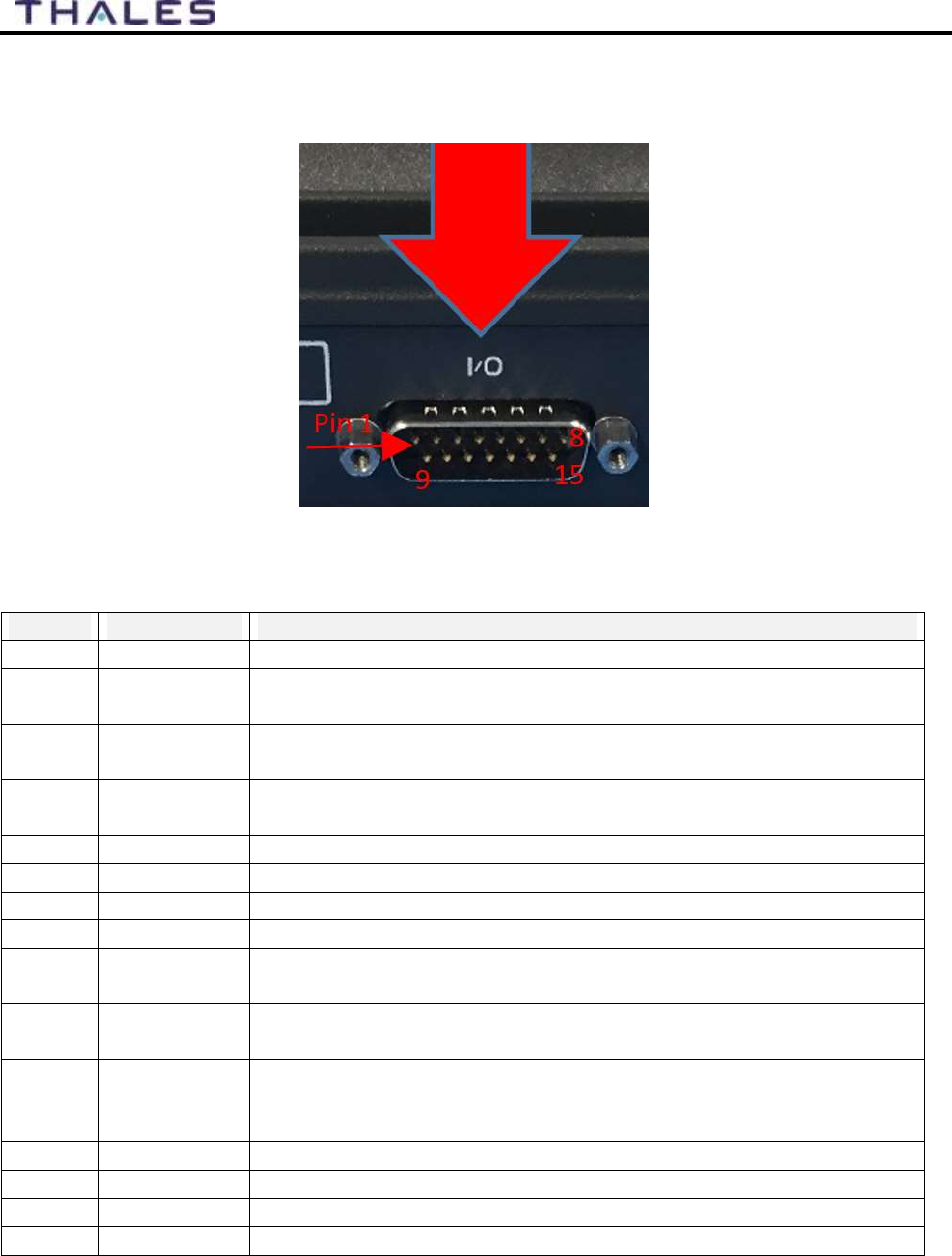
7-4
User Manual PN 84468 Rev 1
Connector Location
The DB-15 connector with Pin out shown in Figure 7-2.
Figure 7-2 GPIO Connector Pin Detail
Table 7-4 GPIO Connector Pin Definition
Pin No
Name
Description
1
GND1
Ground
2
Audio_In +
Radio Gateway functionality, differential (+) Hi-Z Audio Input from
external Radio
3
Audio_Out +
Radio Gateway functionality, Differential (+) Low-Z Audio Output
to external radio (mic input)
4
RadioCOR
Radio Gateway functionality, Radio initiated voice into terminal
(optional)
5
SOS_IN
SOS remote functionality, Ground pin to activate internal SOS
6
GPI01
Software configurable GPIO pin #1 (future)
7
RS232_TD
RS232 Output (future)
8
GND2
Ground
9
Audio_In -
Radio Gateway functionality, differential (-) Hi-Z Audio Input from
external Radio
10
Audio_Out -
Radio Gateway functionality, Differential (-) Low-Z Audio Output
to external radio (mic input)
11
RadioPTT
Radio Gateway functionality, Putput PTT from terminal to external
radio, short to ground for PTT enabled, Open drain requires external
10k pullup resistor
12
GND3
Ground
13
GPI02
Software configurable GPIO pin #2 (future)
14
RS232_RD
RS232 Input (future)
15
12V
+12V output, 100mA
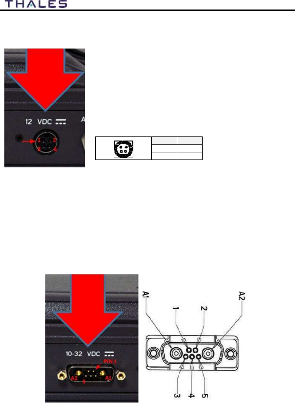
7-5
User Manual PN 84468 Rev 1
PIN NO
OUTPUT
2, 4
+V
1, 3
-V
VIEW INTO END OF MATING CONNECTOR
2
4
1
3
TU 12V Connection Detail
Type: KPPX-4x connector (or similar) shown in Figure 7-3.
Figure 7-3 12V Input and Mating Connector Detail
TU 10-32VDC Connection Detail
Type: 684M7W2103L201 connector (or similar) shown in Figure 7-4.
A1 = V+ /10-32VDC
A2 =V- /GND
Pin 5 = Ignition
Figure 7-4 10-32 VDC and Mating Connector Detail

8-1
User Manual PN 84468 Rev 1
ACRONYMS / GLOSSARY CHAPTER 8
ACRONYMS / GLOSSARY
Table 8-1 List of Acronyms
Acronym
Description
AC
Alternating Current
API
Application Programming Interface
BAA
Broadband Active Antenna
BAE
Broadband Application Electronics
BCX
Broadband Core Transceiver
BIT
Built In Test
DC
Direct Current
DHCP
Dynamic Host Configuration Protocol
DTMF
Dual Tone Multi-Frequency
EBB
Enhanced Broadband
ETSI
European Telecommunications Standards Institute
GPIO
General Purpose Inputs/Outputs
GPS
Global Positioning System
HGA
High Gain Antenna
HRLP
High Speed Radio Link Protocol
HTTP
Hypertext Transfer Protocol
ICMP
Internet Control Message Protocol
IP
Internet Protocol
ITU
International Telecommunications Union
LAN
Local Area Network
LED
Light Emitting Diode
LEO
Low Earth Orbiting
LGA
Low Gain Antenna
LOS
Line of Site
MO
Mobile Originated
MT
Mobile Terminated
NAS
Network Attached Storage
PBX
Private Branch Exchange
PCM
Pulse Code Modulation
PoE
Power Over Ethernet
POST
Power On Self-Test
POTS
Plain Old Telephone Service
PSTN
Public Switched Telephone Network
QSG
Quick Start Guide
R/W
Read/Write
RF
Radio Frequency
SBC
Smart Battery Charger

8-2
User Manual PN 84468 Rev 1
Acronym
Description
SIM
Subscriber Identity Module
SIP
Session Initiation Protocol
SMBus
System Management Bus
SV
Satellite Vehicle
TCP
Transmission Control Protocol
TDSI
Thales Defense & Security, Inc.
TLS
Transport Layer Security
TU
Terminal Unit
UDP
User Datagram Protocol
UL/DL
Uplink/Downlink
VLAN
Virtual Local Area Network
VOIP
Voice of Internet Protocol
WAN
Wide Area Network
Wi-Fi
Wireless Network
WPA2-PSK
Wi-Fi Protected Access 2 – Pre-Shared Key
Table 8-2 List of Definitions
Acronym
Description
API
Application Programming
Interface
The Management Portal provides API to allow for the
connection to the terminal remotely.
BAA
Broadband Active
Antenna
The antenna and supporting electronics that interface an
Iridium satellite terminal with the Iridium constellation
BAE
Broadband Application
Electronics
Hardware and software platform resident in the TU that
interfaces with the BCX, BAA and user devices
BCX
Broadband Core
Transceiver
Hardware designed for an Iridium satellite terminal to
interface end-user equipment with an Iridium BAA
BIT
Built In Test
Diagnostic testing for system integrity check and error
reporting
DHCP
Dynamic Host
Configuration Protocol
1. The Dynamic Host Configuration Protocol (DHCP) is a
system used in computer networking to automatically
assign networking information to a client.
DTMF
Dual Tone Multi-
Frequency
Signals generated from phone keypad
EBB
Enhanced Broadband
EBB Mode is Iridium NEXT phase 1 EBBS (Enhanced
Broadband Service)
ETSI
European
Telecommunications
Standards Institute
Organization that maintains standards for Information
and Communications applicable to fixed and mobile
radio platforms
GPIO
General Purpose
Inputs/Outputs
General use pins
HGA
High Gain Antenna
External antenna that connects to the TU via a coaxial
cable. The HGA2 (also called BAA-H2) provides 352
kbps uplink and downlink capability
HRLP
High Speed Radio Link
Management of In-band signaling on broadband

8-3
User Manual PN 84468 Rev 1
Acronym
Description
Protocol
channels
HTTP
Hypertext Transfer
Protocol
Protocol to exchange or transfer hypertext
ICMP
Internet Control Message
Protocol
Protocol by network devices that typically send error
messages and is used for diagnostics
ITU
International
Telecommunications
Union
Agency of the United Nations responsible for issues
concerning information and communications
technologies
LED
Light Emitting Diode
Semiconductor that emits colored light
LGA
Low Gain Antenna
External antenna that connects to the TU via a coaxial
cable. The LGA1 and LGA2 support the future Certus™
100 and Certus™ 200 capabilities
Management
Portal
Management Portal: A web page served from the
Terminal Unit that brings together the diverse status and
configuration information of the TU in one place.
MO
Mobile Originated
Calls originating from the terminal
MT
Mobile Terminated
Calls terminating at the terminal
NAS
Network Attached Storage
Ability to store and retrieve files to/from a physical
memory storage device attached to the network
PBX
Private Branch Exchange
Telephone connection between local users not requiring
external phone connection
POST
Power On Self-Test
BIT Test performed at the turn-on of the TU
POTS
Plain Old Telephone
Service
A voice-grade telephone service that utilizes analog
signal transmission over copper loops
PSTN
Public Switched
Telephone Network
The world's collection of interconnected voice-
orientable public telephone networks, both commercial
and government owned.
R/W
Read/Write
Capability
SIM
Subscriber Identification
Module
Iridium provided method to authenticate and identify
subscriber
SIP
Session Initiation Protocol
An Internet Engineering Task Force (IETF) standard
protocol for initiating an interactive user session that
involves multimedia elements such as video, voice, and
chat
SMBus
System Management Bus
Two-wire bus for communications between devices
such as a Terminal and a Smart Battery
SV
Satellite Vehicle
Iridium Satellite
TCP
Transmission Control
Protocol
Core internet protocol that provides reliable delivery
and error-checking
TLS
Transport Layer Security
TLS is on the standard way that computers on the
internet transmit information over an encrypted channel.
TU
Terminal Unit
Electronic equipment that contains the BCX and the
BAE
UDP
User Datagram Protocol
Connectionless transmission model with minimum , no-
handshaking protocol
UL/DL
Uplink/Downlink
To and from satellite communications
VLAN
Virtual Local Area
Network
For context within this document, VLAN more
specifically designates an Ethernet VLAN. A VLAN is

8-4
User Manual PN 84468 Rev 1
Acronym
Description
establishes a broadcast domain that is partitioned
WPA2-PSK
Wi-Fi Protected Access 2
– Pre-Shared Key
Method of securing a Wi-Fi network
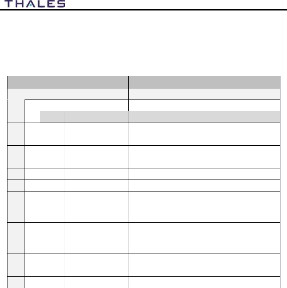
9-1
User Manual PN 84468 Rev 1
SPARE PARTS CHAPTER 9
SPARE PARTS
The following list of equipment can be purchased as a kit or separately, depending on your
requirements and/or needs.
Table 9-1 List of Equipment
IRIDIUM System Part Number
Description
MF700BV
Kit, MissionLINK Vehicular High Gain 700**
MF350BV
Kit, MissionLINK Vehicular High Gain 350**
Qty
Part Number
Description
1
1100789-501
Kit, Terminal Unit, Mounting Hardware
1
1100790-501
Kit, Antenna Magnetic Mount
1
1100792-501
Kit, Antenna Mounting Hardware Land
1
1600899-1
Broadband Active Antenna (BAA)
1
4102947-502
Terminal Unit 350, IRIDIUM CERTUS™ Land
1
4102947-504
Terminal Unit 700, IRIDIUM CERTUS™ Land
1
855021-010
Cable TNCM-TNCM Coax TWS (LMR) 240 Mat
10Ft
1
855024-020
Cable, Vehicle Power Harness 20Ft
1
855026-010
Cable Cat-5e Patch RJ45M-RJ-45M Blue 10ft
1
85728-001
Antenna 2.4 GHz Dipole 2dBi Rev Pol SMA 50
OHM
1
3900011-1
Template, Terminal Unit Mount
1
3900013-1
Template, Land BAA Mount
1
3402174-1
MissionLINK Quick Start Guide
** The MF700BV kit includes the future software upgrade for 700 kbps downlink speeds
whereas the MF350BV does not. The MF350BV is capable of the 700 kbps downlink
speeds and the option can be purchased separately.
Note: The SIM card is provided by the airtime service provider and may be packaged
separately from this kit.
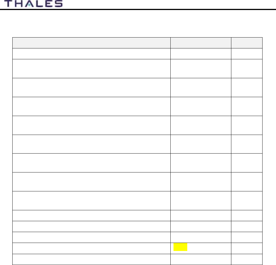
9-2
User Manual PN 84468 Rev 1
Table 9-2 MissionLINK Accessories
Description
Part Number
Qty
Power Supply, AC/DC 12V – 160W
84670-001
1
Cable AC Power USA Plug Type B IEC 60320-C13
Connect Blk 6ft
854024-001
1
Cable AC Power Euro Plug Type E IEC 320-C14
Connect Blk 6ft
854025-001
1
Cable AC Power AUS Plug Type 1 IEC 320-C14
Connect Blk 6ft
854026-001
1
Cable AC Power UK Plug Type G IEC 320-C13
Connect Blk 6ft
854027-001
1
Cable TNCM-TNCM Coax TWS (LMR) 240 Mat
20Ft
855021-020
1
RF Cable TNCM-TNCM COAX TWS (LMR) 240
MAT 30Ft
855021-030
1
RF Cable TNCM-TNCM COAX TWS (LMR) 240
MAT 50Ft
855021-050
1
RF Cable TNCM-TNCM COAX TWS (LMR) 400
MAT 100ft (Fixed Locations)
855022-100
1
Cable, Vehicle Power Harness 20ft
855024-020
1
Cable Cat-5e Patch RJ45M-RJ-45M Blue 10ft
855035-010
1
Antenna 2.4 GHz Dipole 2dBi Rev Pol SMA 50 OHM
85728-001
1
SS Clip and Knob for IP Handset
TBD
1
Thales SureLINK IP Handset with 6ft Coil Cord
1600913-1
1

Thales Defense & Security, Inc.
22605 Gateway Center Drive | Clarksburg MD 20871
Toll-Free 1.800.324.6089 | Phone: 240.864.7000 | Fax: 240.864.7920
Email: Customer.Service@thalesdsi.com | Website:
www.thalesdsi.com