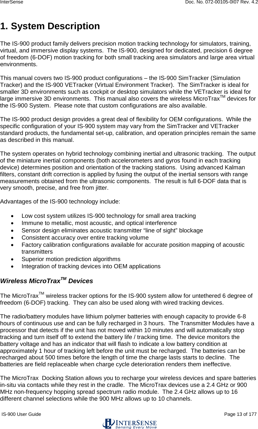
Thales Visionix 9SMLW Ultrasonic Tracking Device User Manual Version 2 2
Thales Visionix, Inc. Ultrasonic Tracking Device Version 2 2
UserManual.wiki
>
Thales Visionix
>
9SMLW User Manual
User Manual.pdf
Navigation menu
Upload a User Manual
Namespaces
Wiki Guide
HTML
PDF
Info
Views
User Manual
Discussion / Help
Navigation
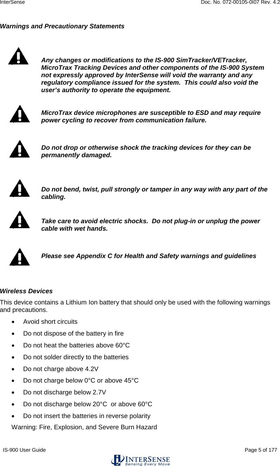
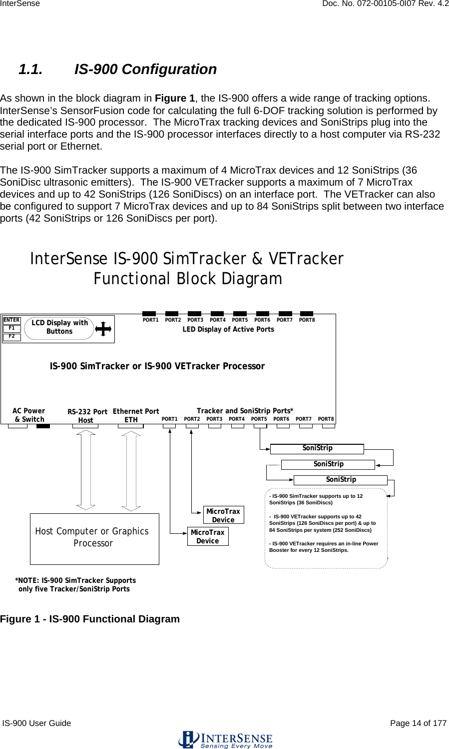
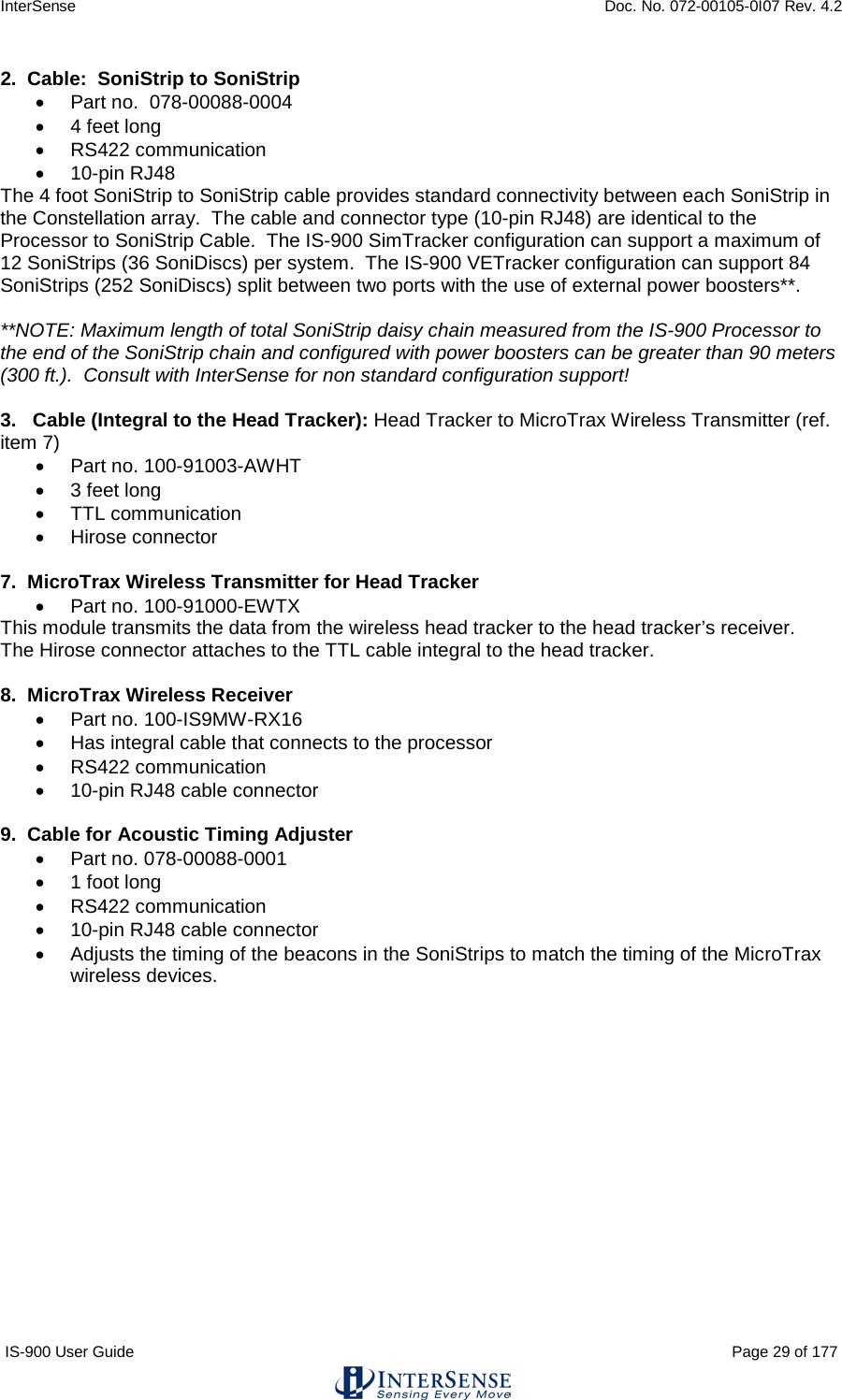
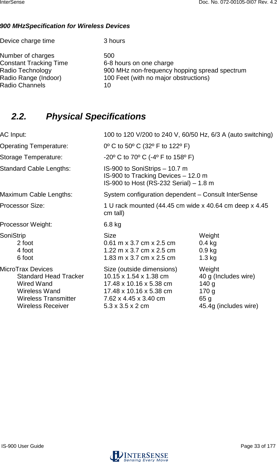
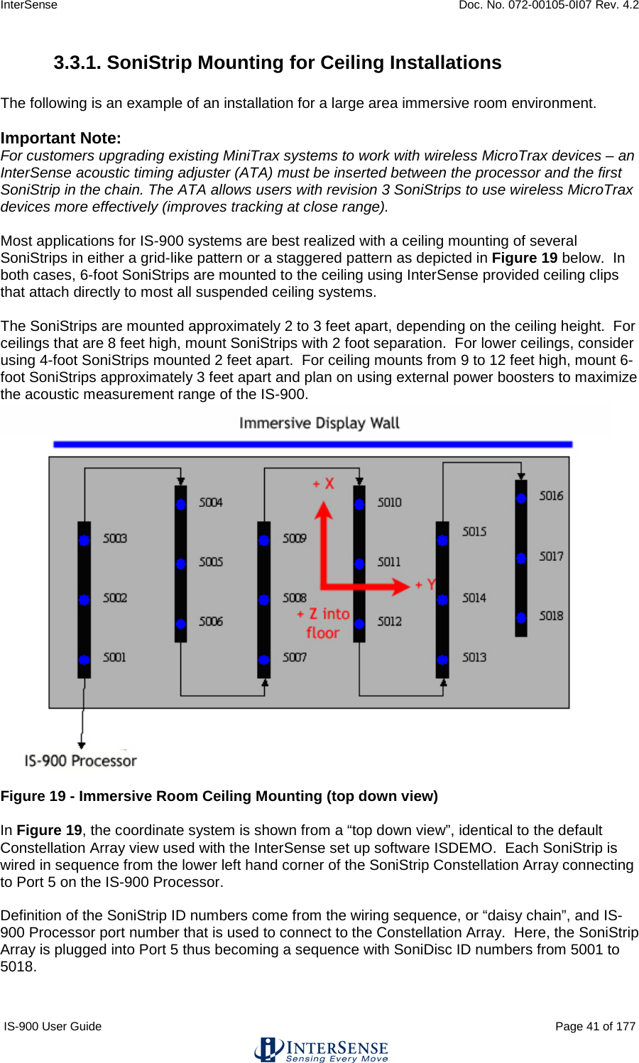
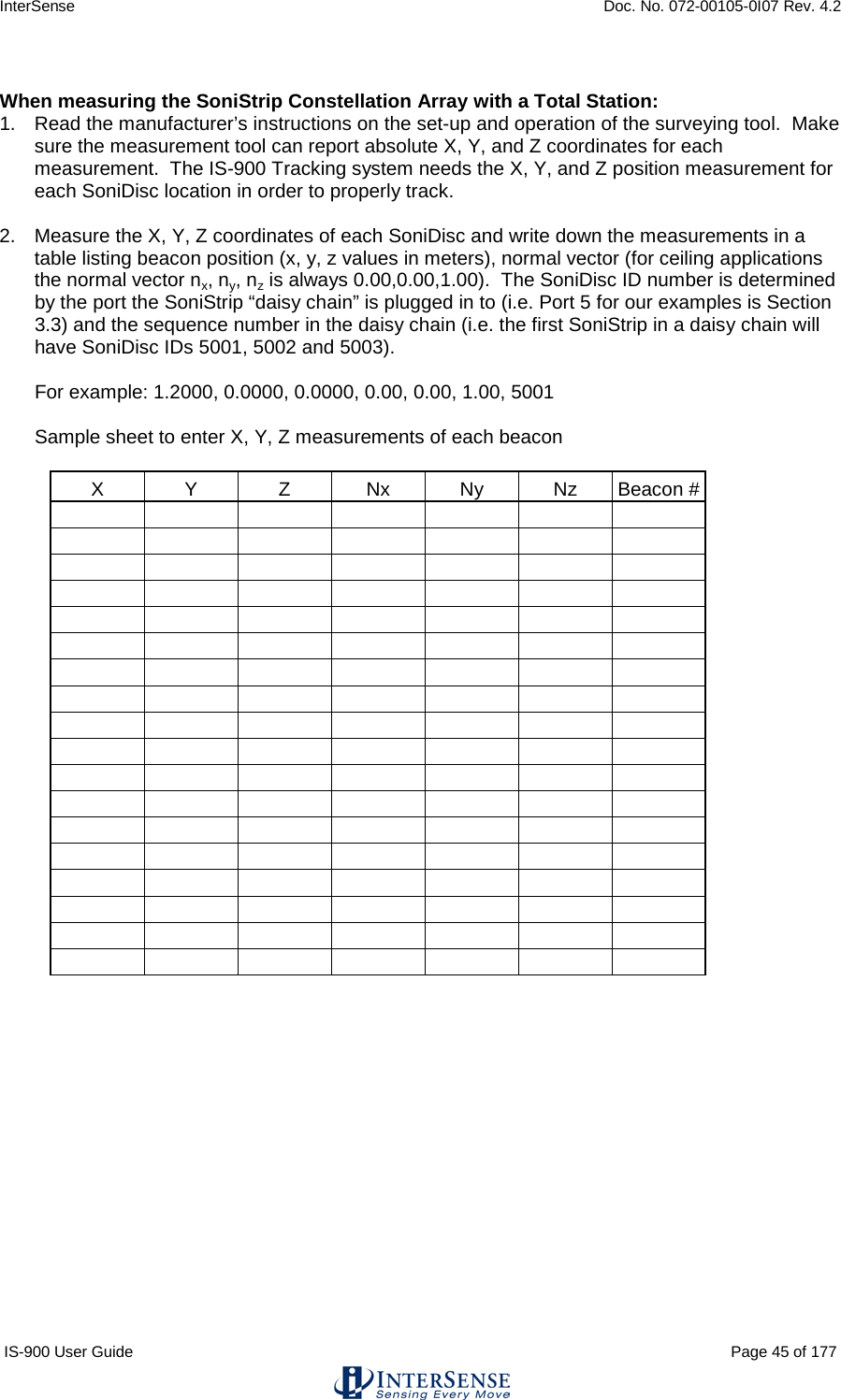
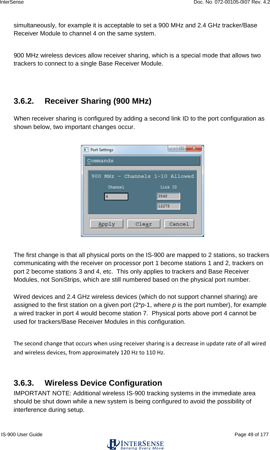
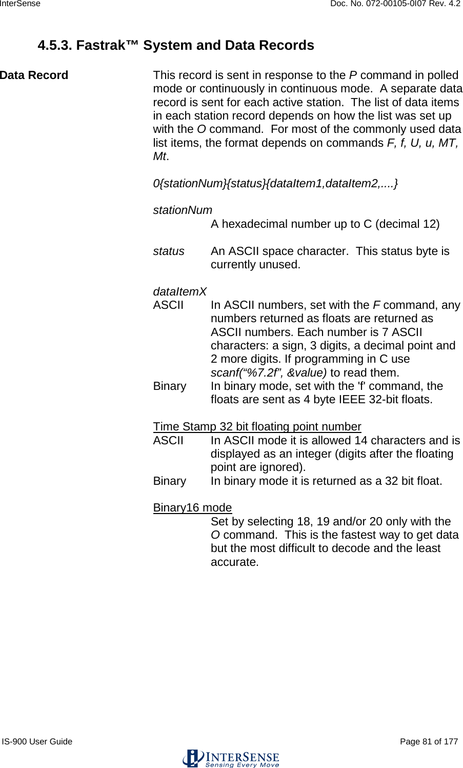
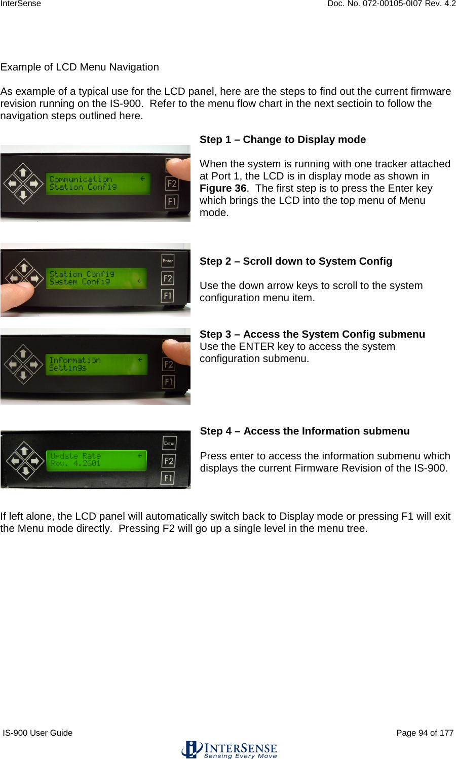
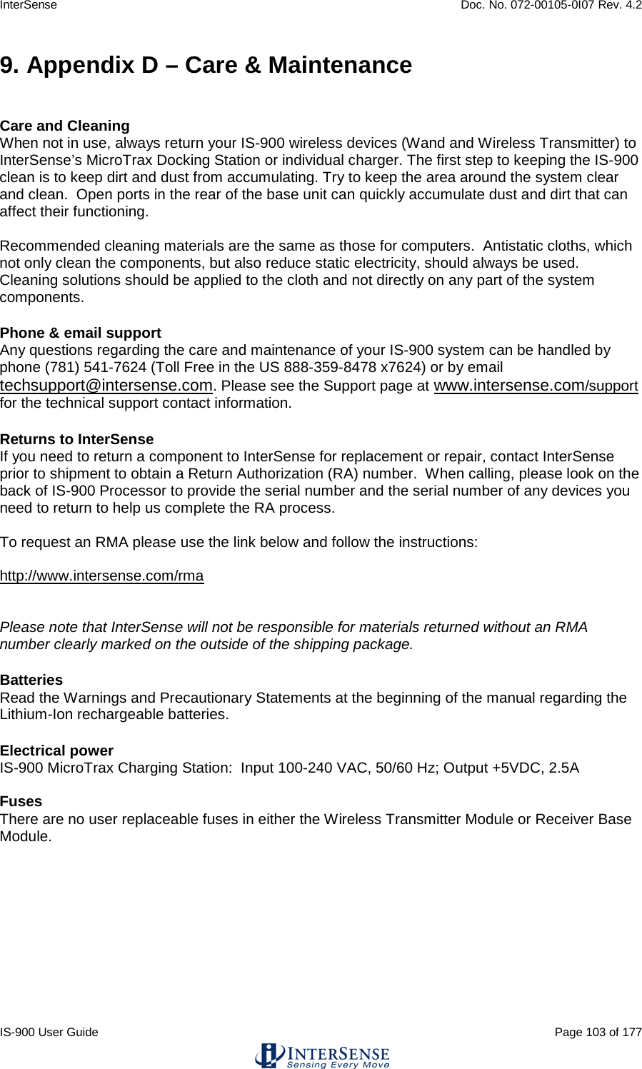
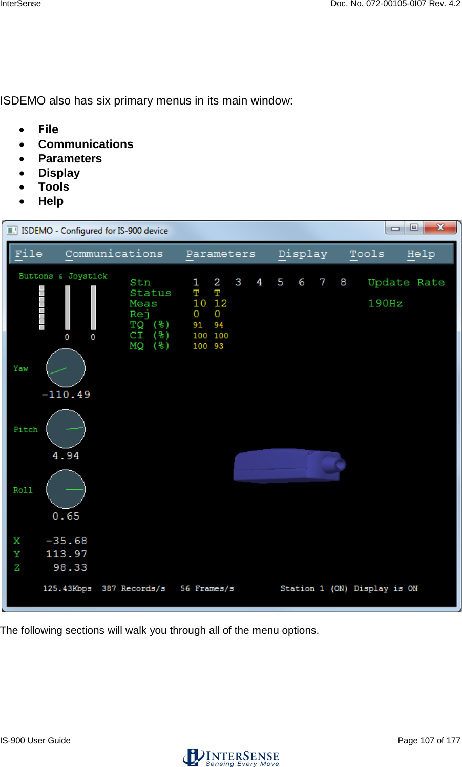
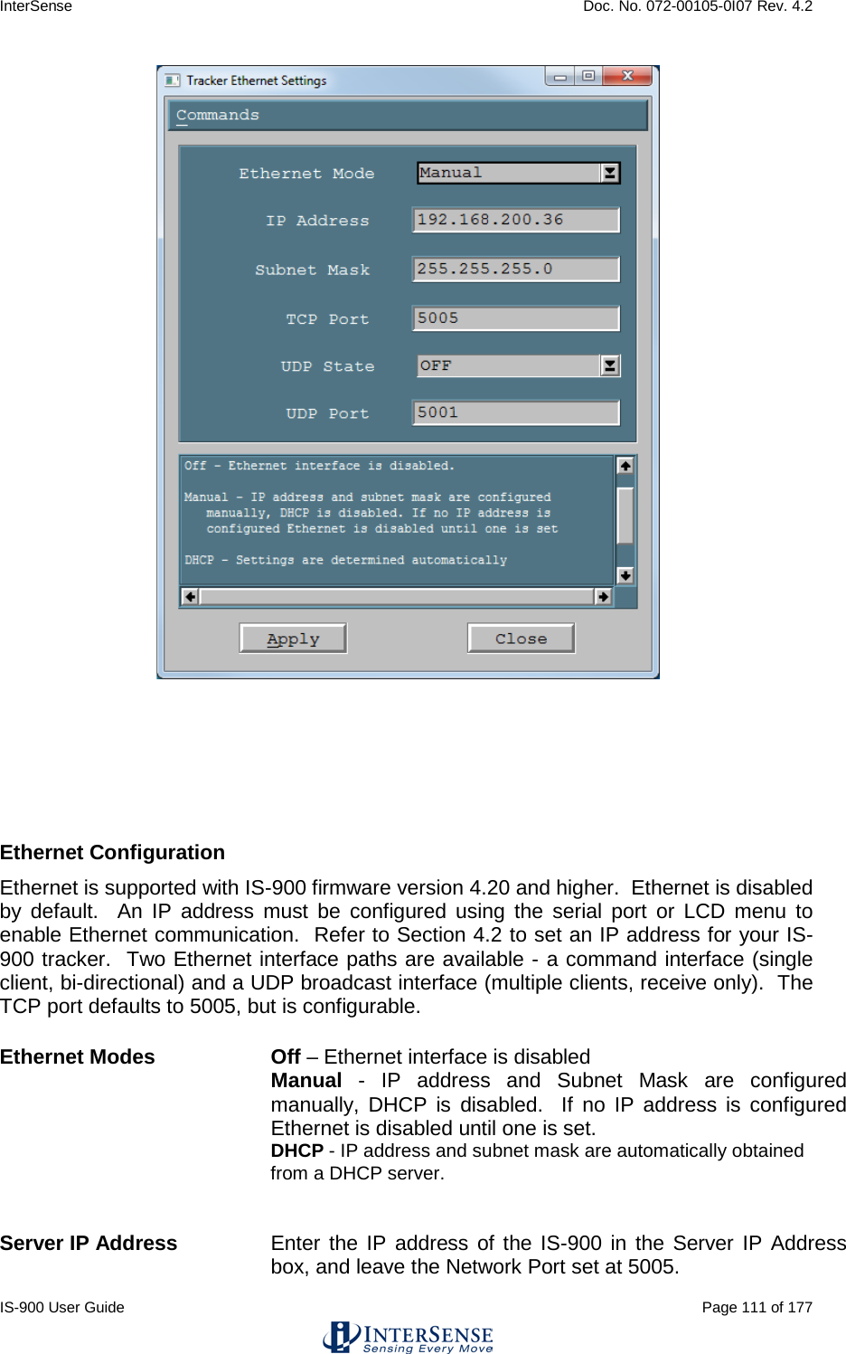
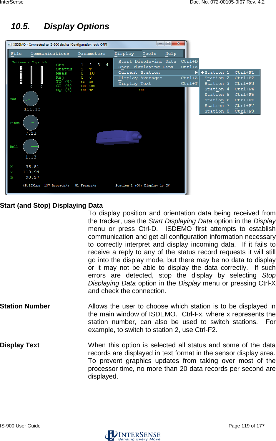
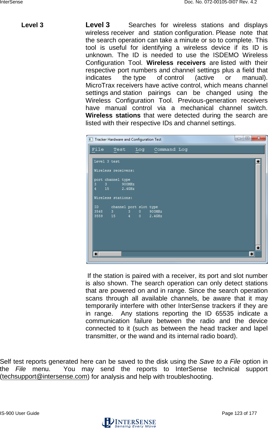
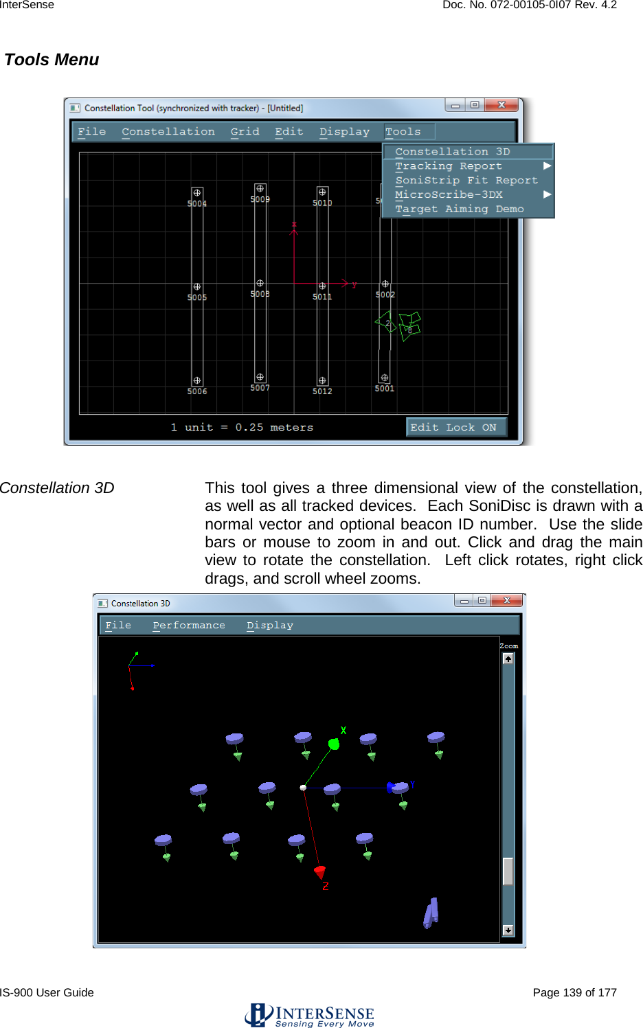
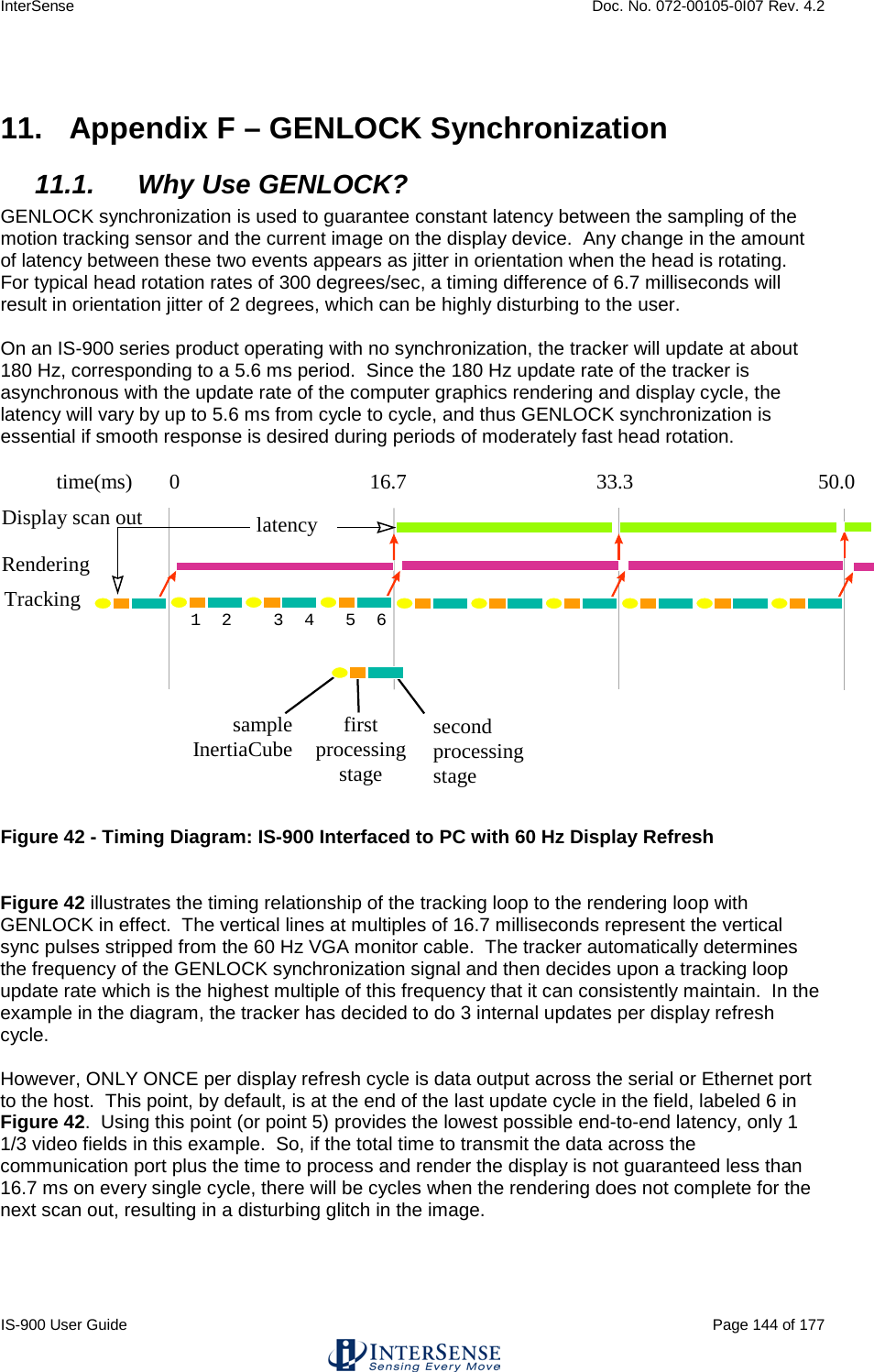
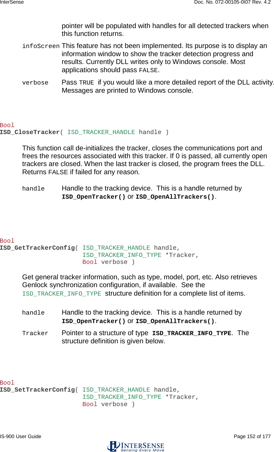
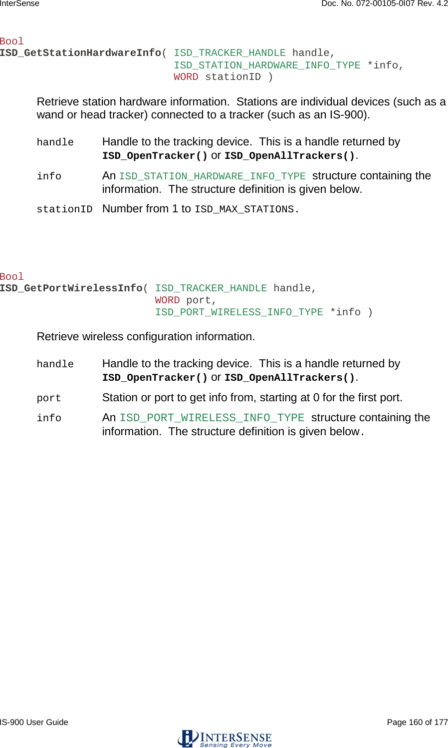
![InterSense Doc. No. 072-00105-0I07 Rev. 4.2 IS-900 User Guide Page 63 of 177 4. Interface Communication Protocol For firmware version 4.20 or higher Terminology Throughout this section and the ISDEMO program described in Section 10, certain terms and acronyms are used to reference functional components of all InterSense tracking systems. Specifically, IS-900 models contain an ultrasonic subsystem that includes SoniDiscs (Ultrasonic Transponder Beacons) and Microphones (Ultrasonic Receiver Modules – URMs). To generalize the interface protocol and configuration tools for these tracker models, InterSense uses the term: PSE - Position Sensing Element. A PSE may be Mobile or Fixed. Mobile PSEs are assigned to the stations and their movements are tracked by the system (i.e. MicroTrax Microphones). Fixed PSEs form a CONSTELLATION that is used as a reference for tracking (i.e. SoniStrips & SoniDiscs). In the case of IS-900 tracking systems, Microphones are mobile and SoniDiscs are fixed. 4.1. Commands Sent from the Host to the Tracker <> Carriage return line feed pair- not needed for single character commands. CR – ASCII value 13, LF – ASCII value 10. {} List of parameters required for command. [] List of optional parameters for command. Omitting those results in a query. The IS-900 emulates most (but not all) of the commands in the Polhemus Fastrak™ protocol, thus it is possible to use the IS-900 with most applications without writing new driver code. There are also several additional commands added to access some of the advanced features of the IS-900 that do not have any counterpart in the Fastrak™ protocol. Note: Firmware version 3.xx extended Fastrak™ protocol to support up to 32 stations (actual number allowed is determined by your hardware configuration). StationNum in commands, status and data records is now encoded in an extended hexadecimal notation. Numbers 1 to F conform to standard hexadecimal notation, with numbers greater that F represented by additional upper case letters of the alphabet. For example, number 16 is displayed as G. 4.2. Standard Fastrak™ Interface Commands Data Record Request P Request a data record from all active stations. Only used in polled mode. Output mode C Put in continuous output mode. c Put in polled output mode. Default Polled mode](https://usermanual.wiki/Thales-Visionix/9SMLW/User-Guide-2168100-Page-63.png)
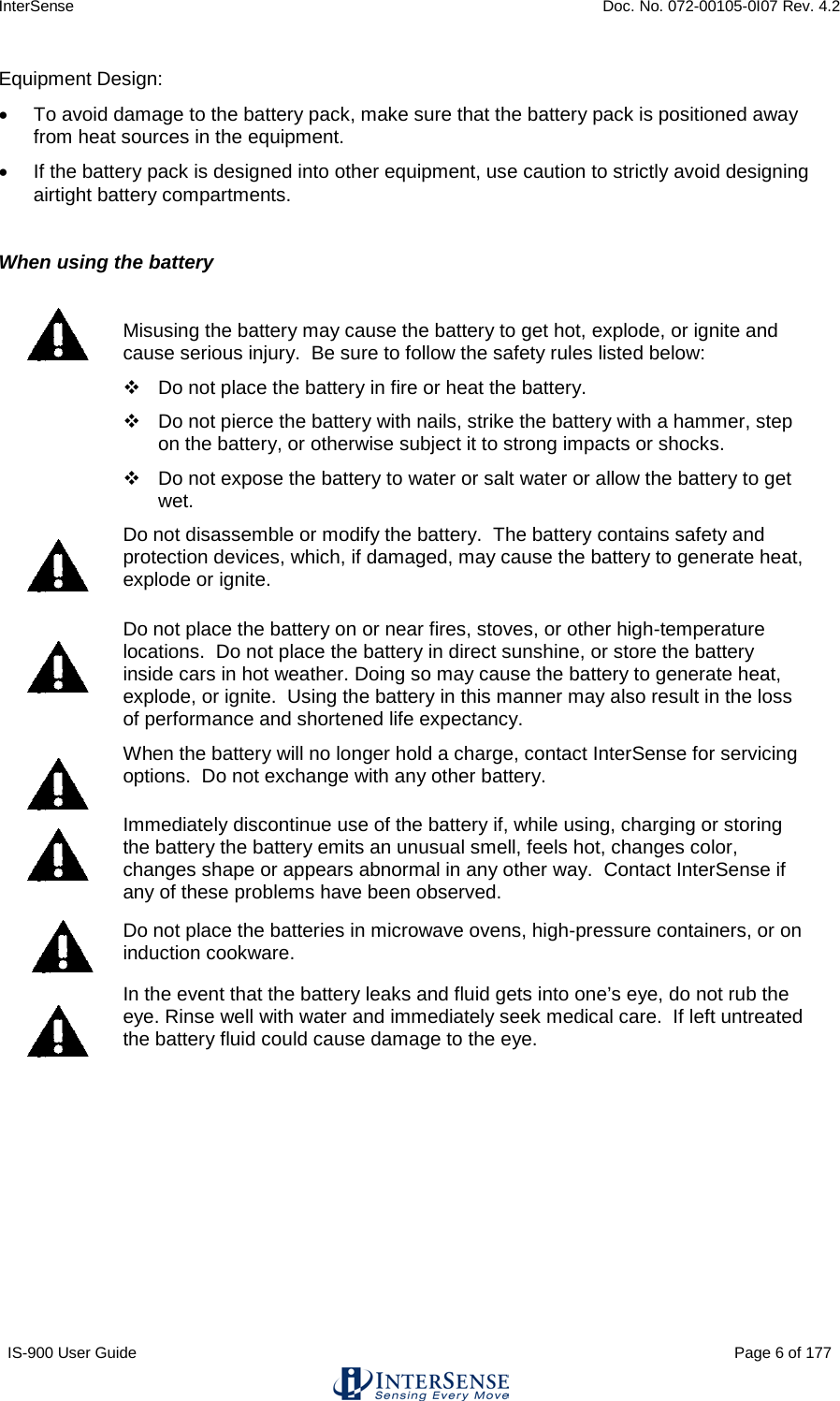
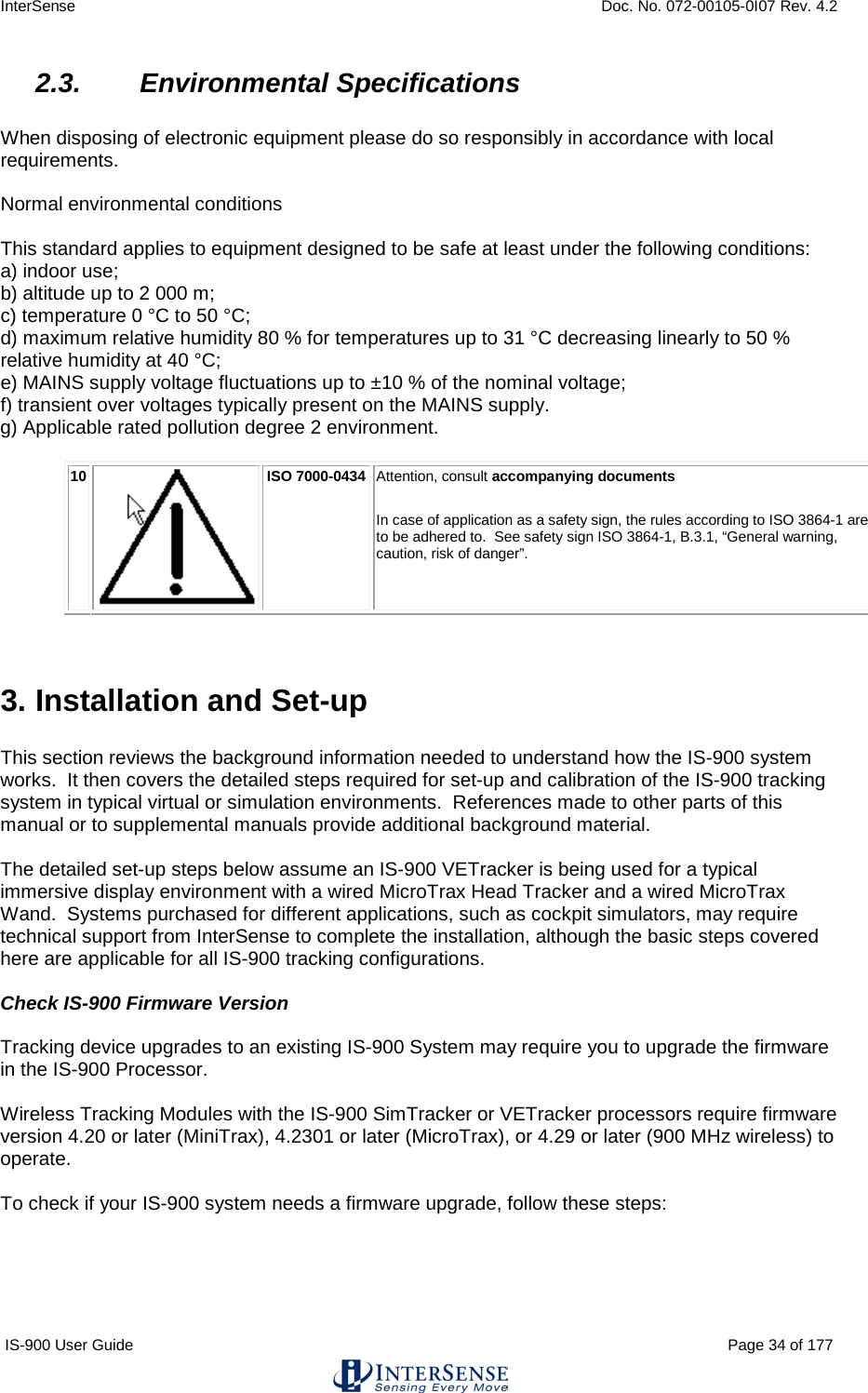
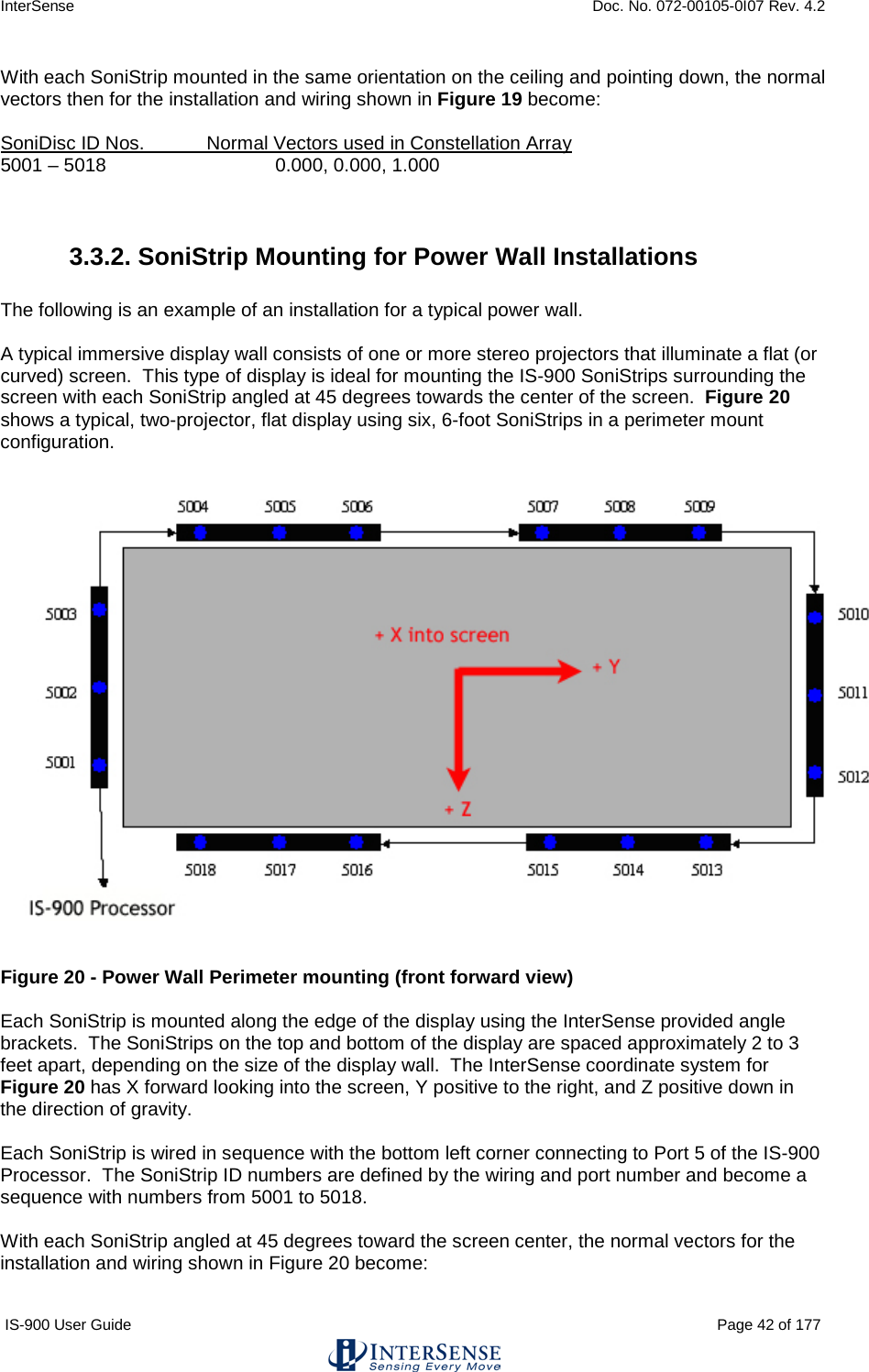
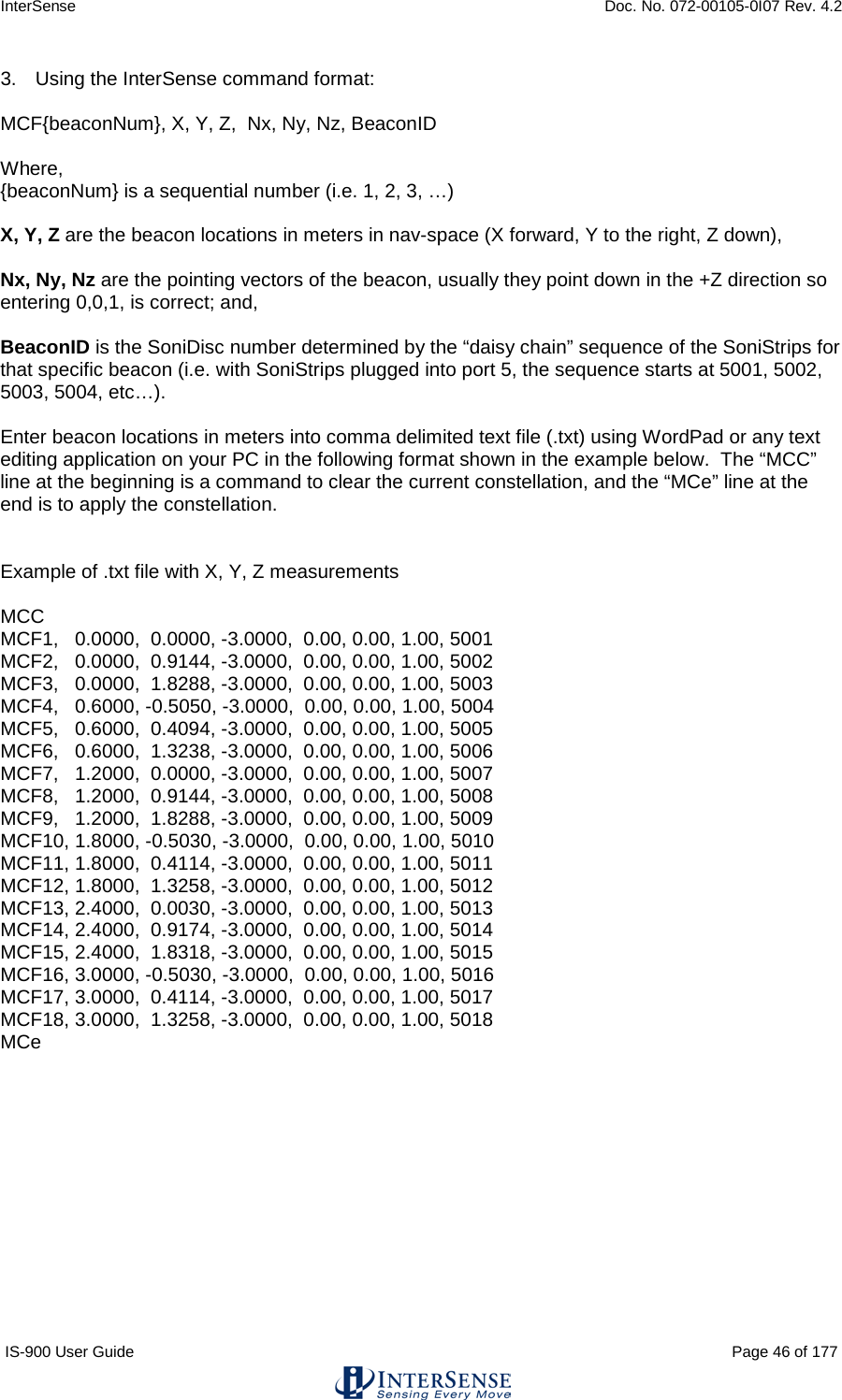
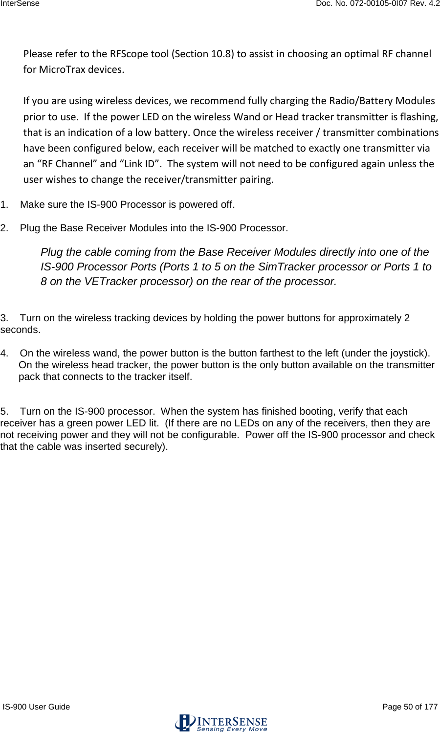
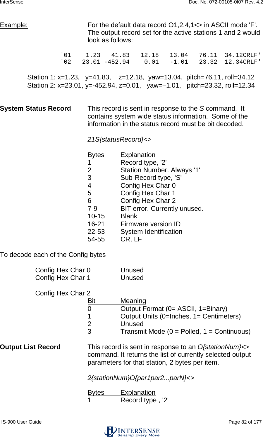
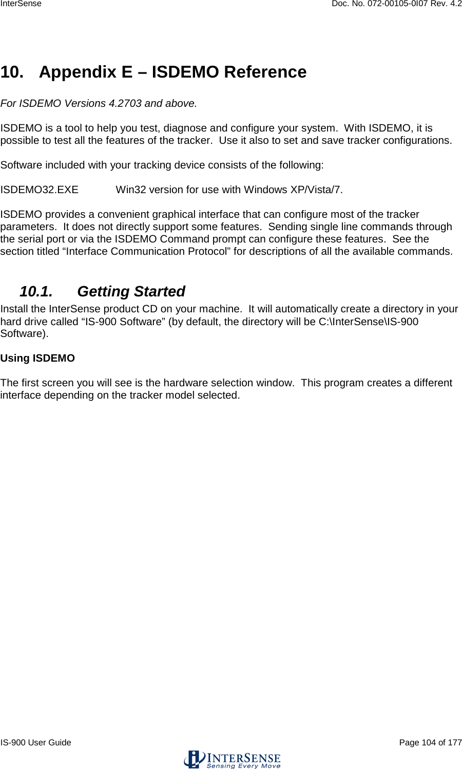
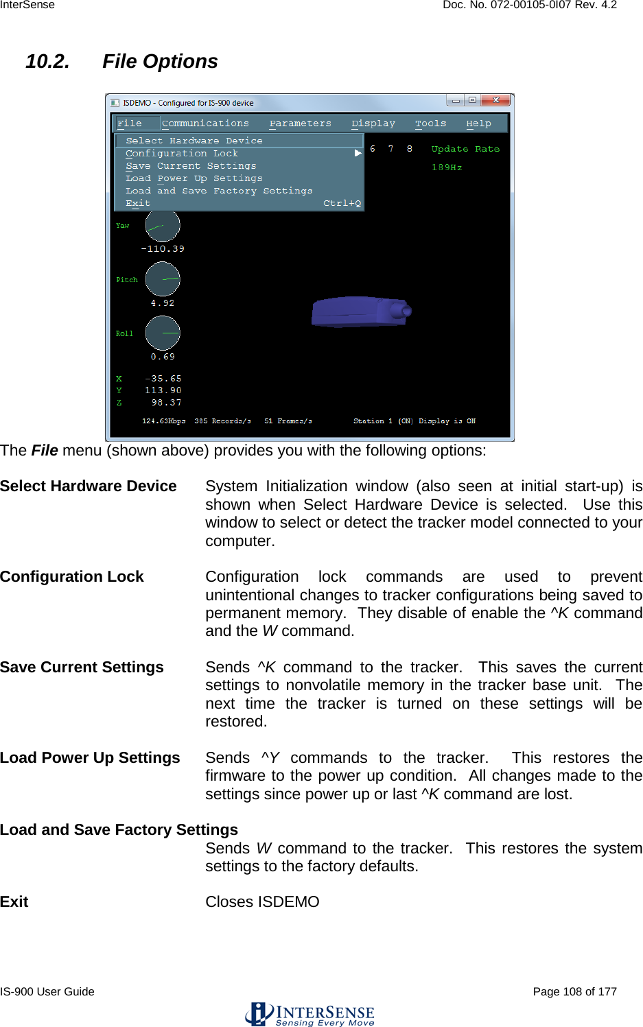
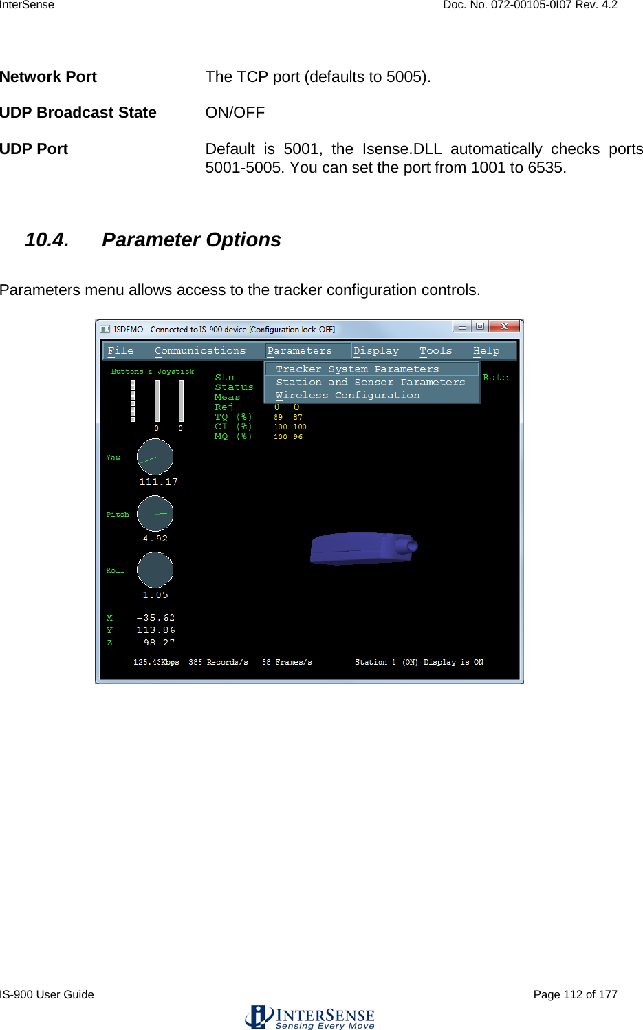
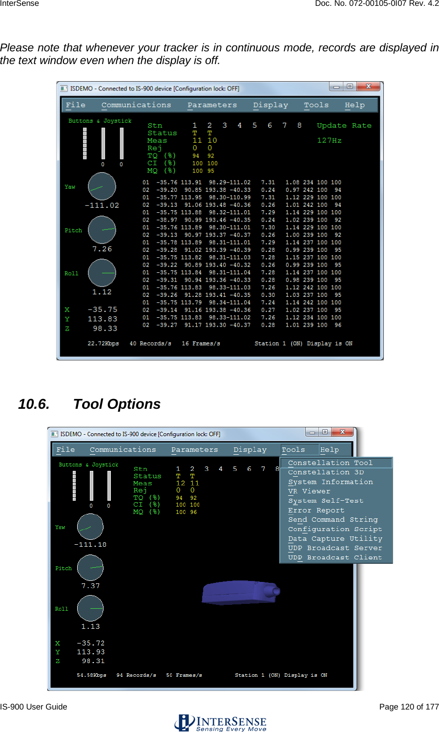
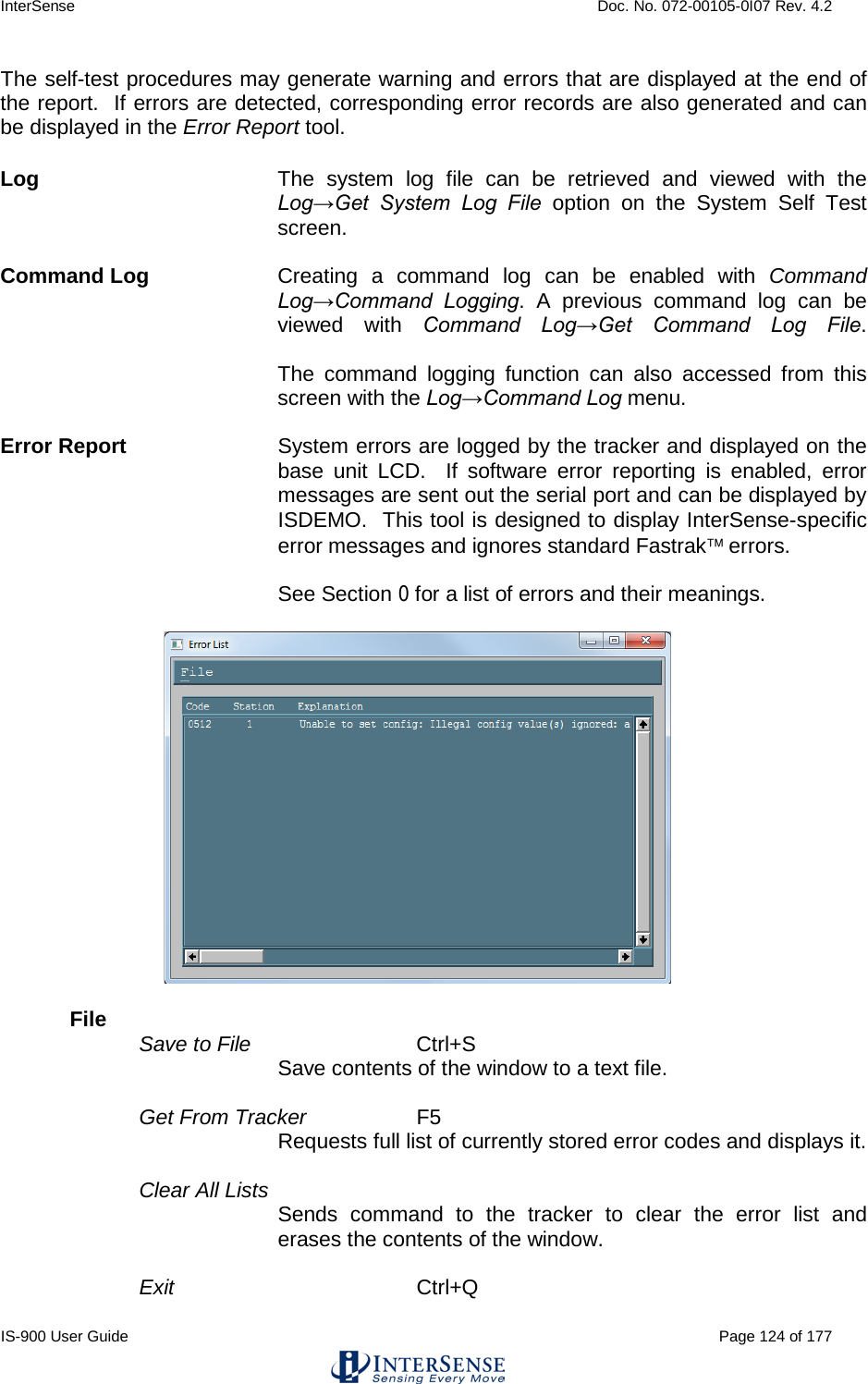
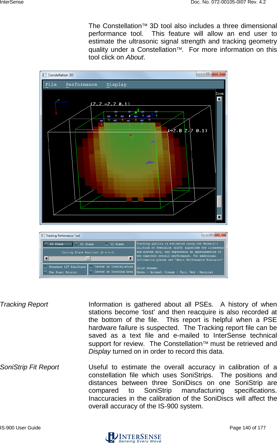
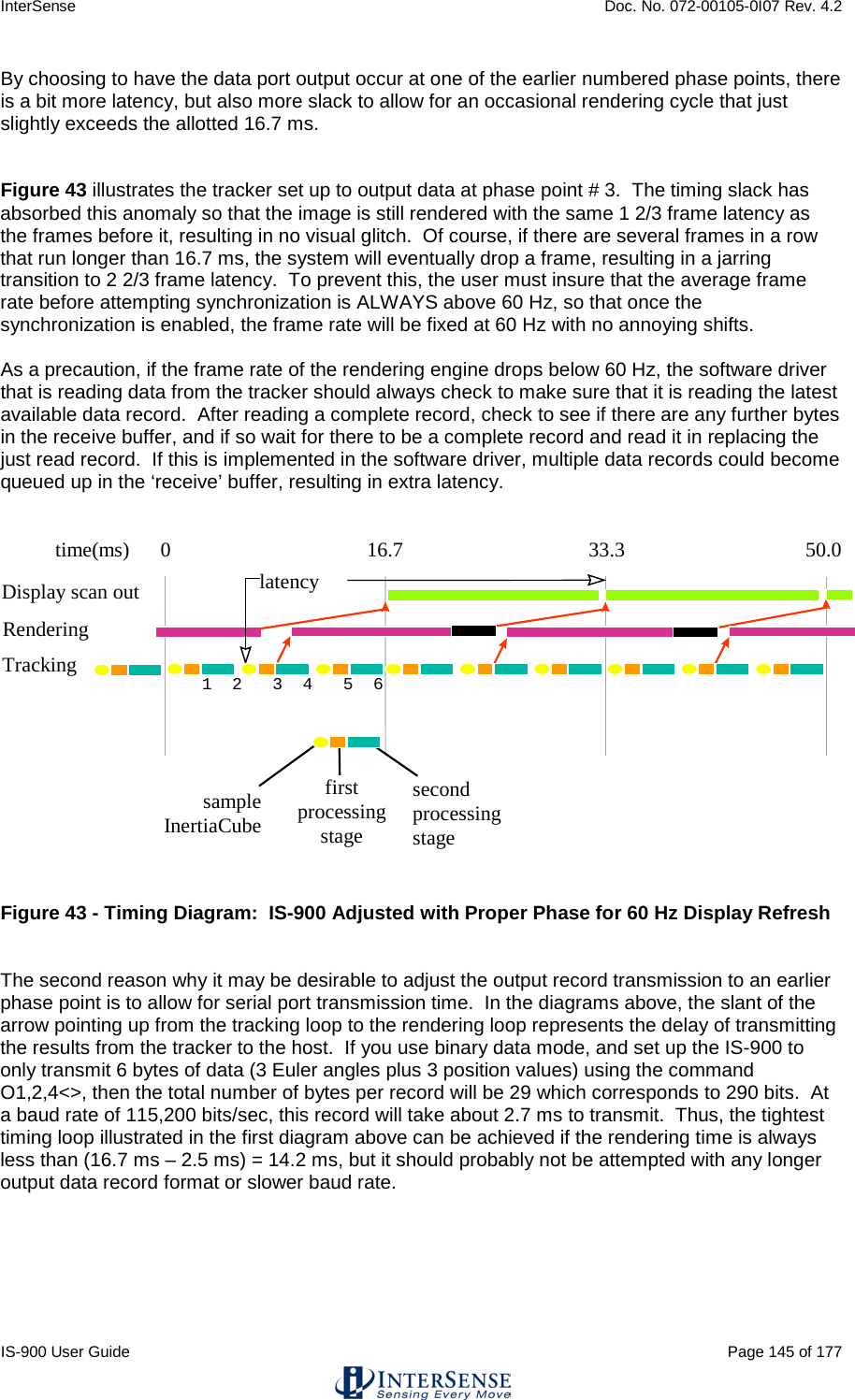
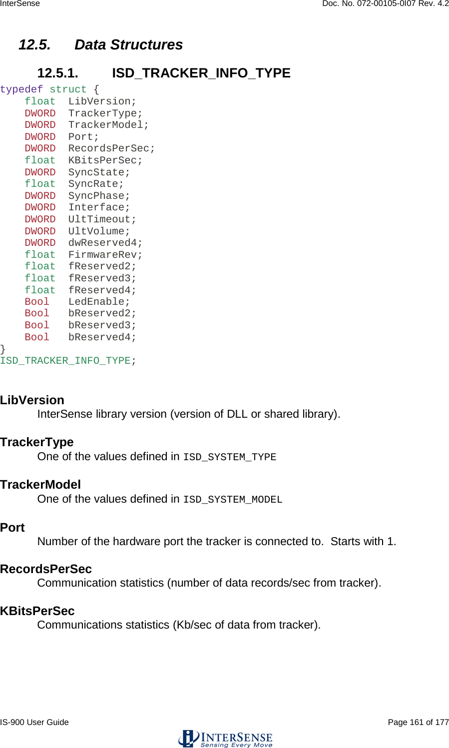
![InterSense Doc. No. 072-00105-0I07 Rev. 4.2 IS-900 User Guide Page 64 of 177 Alignment Reference Frame A{stationNum},[Ox,Oy,Oz,Xx,Xy,Xz,Yx,Yy,Yz]<> Sets the coordinate frame with respect to which outputs for that station will be reported. The coordinate frame is defined by a set of three points. Ox,Oy,Oz defines the origin of the new coordinate system, Xx,Xy,Xz defines a point on the positive x-axis and Yx,Yy,Yz defines a point on the positive y-axis. The points on the positive X and positive Y axis are in the new coordinate frame rather than the original coordinate frame. Values are not cumulative/incremental, so any future changes are relative to the original coordinate system. For example, in order to configure station 1 to use a new origin of (50, 60, 70)cm with the coordinate frame rotated 90 degrees about the +Z axis, the command would be A1,50,60,70,50,61,70,49,60,70 (adding +1cm to the Xy value and -1cm to the Yx value). Any length of vector along +X and +Y may be used, as these are normalized internally to a length of 2m (200cm), although for simplicity we recommend adding the same value; in the example, however, the command A1,50,60,70,50,400,70,12,60,70 (adding +340cm to Xy and -38cm to Yx) would cause the same translation/rotation of the coordinate system. If optional parameters are omitted, current values are returned. Units are centimeters. Default Fusion Mode: X=North, Y=East, Z=Down, position origin is defined by SoniStrip Constellation Array horizontally leveled. See Section 3.1. Reset Alignment Reference Frame R{stationNum}<> Resets reference frame to the default. Boresight Reference Angles G{stationNum},[yawref, pitchref, rollref]<> Sets the boresight reference angles for the specified station. If set, these values are then used by the next Boresight command instead of current orientation. If optional parameters are omitted, current reference angles are returned. Units are degrees. Default 0,0,0](https://usermanual.wiki/Thales-Visionix/9SMLW/User-Guide-2168100-Page-64.png)
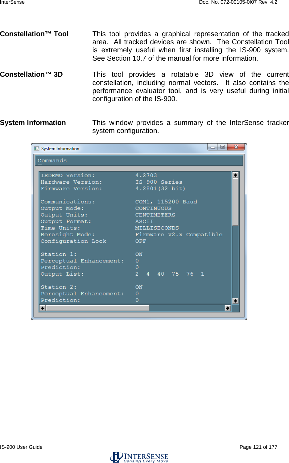
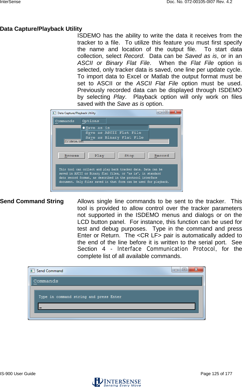
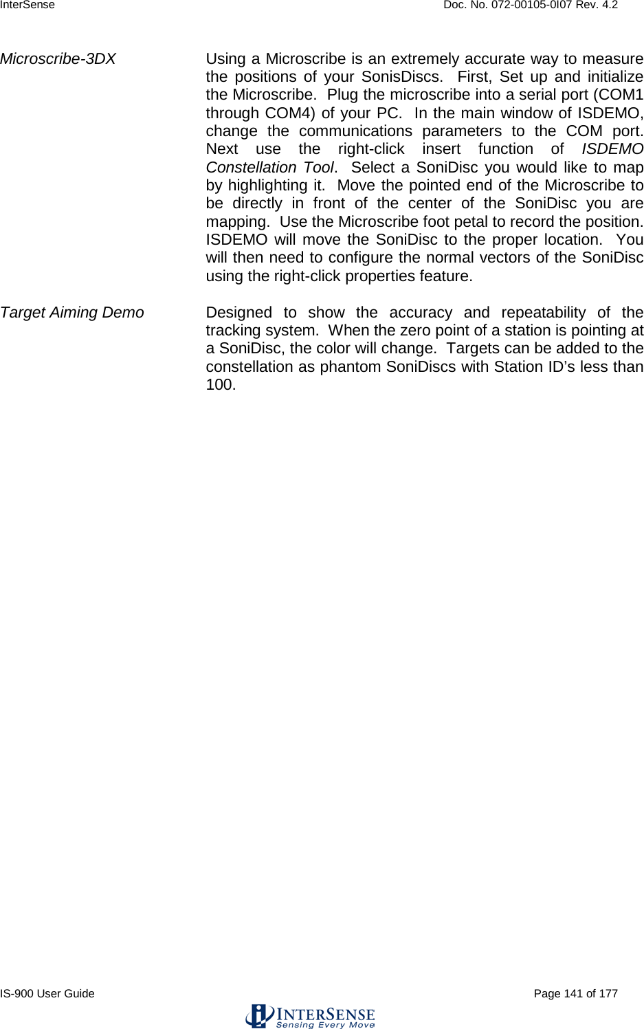
![InterSense Doc. No. 072-00105-0I07 Rev. 4.2 IS-900 User Guide Page 65 of 177 Boresight Compatibility Mode MBF<> Switch system to Fastrak Compatible mode. MBI<> Switch system to Firmware Version 2.x Compatible mode. In firmware versions prior to 3.00 the B{stationNum}<> command was implemented as the Heading Boresight (see below) and full boresight was not available. To maintain compatibility with the user software written at that time, two Boresight Compatibility modes are available. In Fastrak Compatible mode B{stationNum}<> command executes full 3-DOF boresight and MB{stationNum}<> effects heading only. In the Firmware Version 2.x Compatible mode the meanings of these commands are reversed. Default Firmware Version 2.x Compatible, MBI<> Boresight B{stationNum}<> (Fastrak compatibility mode) MB{stationNum}<> (Firmware Version 2.x compatibility mode) Boresight a station. If boresight reference angles have been specified by the G{stationNum}[yawref, pitchref, rollref]<> command prior to issuing of Boresight command then that orientation becomes the new reference point. The angles output by the tracker at that orientation become zero. Otherwise, system uses current station orientation and that becomes the new reference line of sight. Please make sure that the object being tracked (like an HMD) is leveled and is pointing down the x-axis when boresighting a station. Unboresight b{stationNum} <> (Fastrak compatibility mode) Mb{stationNum}<> (Firmware Version 2.x compatibility mode) Unboresight a station. Reference angles are cleared for the specified station. Heading Boresight B{stationNum}<> (Firmware Version 2.x compatibility mode) MB{stationNum}<> (Fastrak compatibility mode) This command has no effect with the IS-900.](https://usermanual.wiki/Thales-Visionix/9SMLW/User-Guide-2168100-Page-65.png)
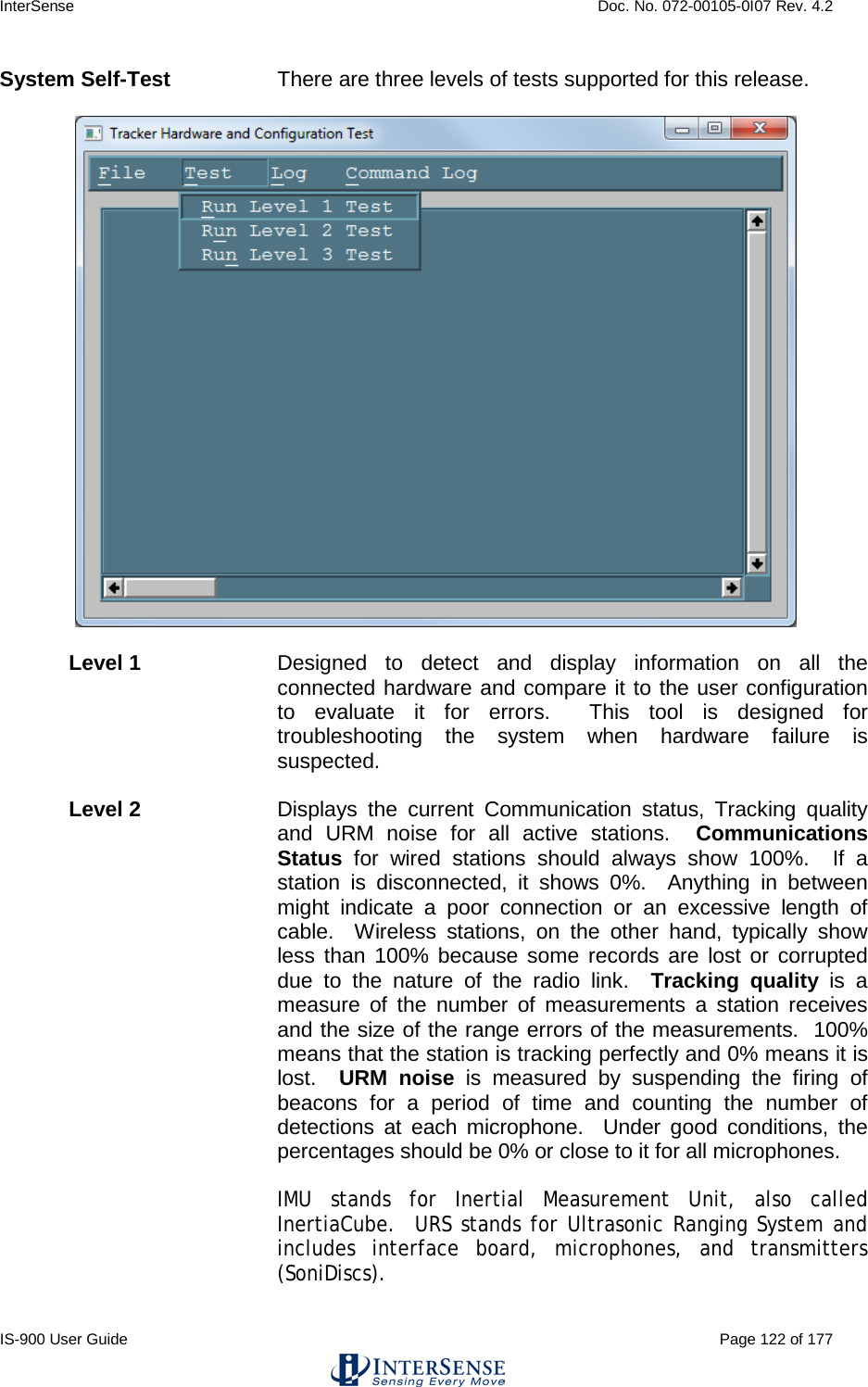
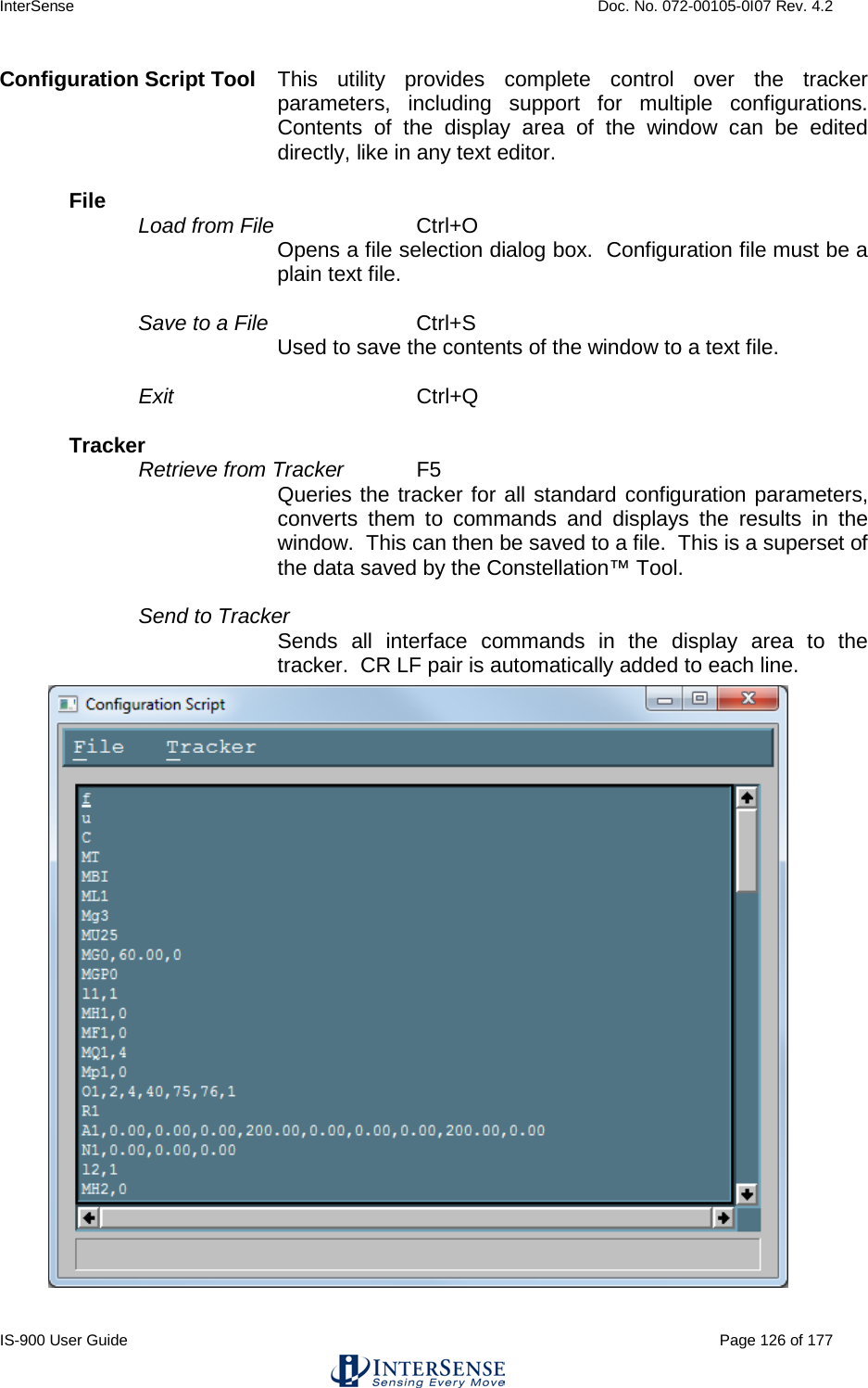
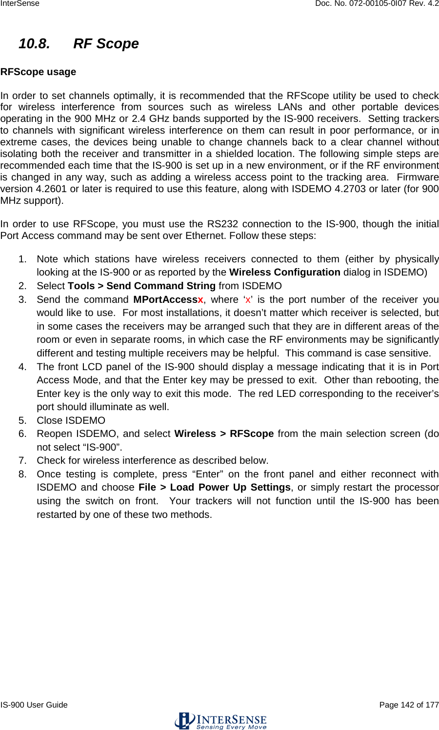
![InterSense Doc. No. 072-00105-0I07 Rev. 4.2 IS-900 User Guide Page 66 of 177 Heading Unboresight b{stationNum}<> (Firmware Version 2.x compatibility mode) Mb{stationNum}<> (Fastrak compatibility mode) This command has no effect with the IS-900. Set Serial Communication Parameters o{rate,parity,bits,HHS}<> Change the serial communication parameters rate is one of 3,12,24,48,96,192,384,576,1152 (rate is multiplied by 100) parity N = none O = odd E = even bits 7 or 8 HHS (Hardware handshake) 0 = OFF 1 = ON Default serial communications settings: rate 1152 parity N bits 8 HHS OFF System Record Request S Request a system status record to be sent. Station Status l{stationNum},[state]<> Set the stationNum on or off. state 0 = OFF, 1 = ON Default All connected stations are on Output Units Control U Sets output data record position units to inches. u Sets the position units to centimeters. These only matter in 6-DOF mode. Default U System control ^K Save the current settings to nonvolatile memory. W Restore the system settings to the factory defaults. ^Y Restart the firmware to the power up condition. ^S Suspend data transmission. ^Q Resume data transmission. Caution: Sending W command will cause all the user configuration information to be lost.](https://usermanual.wiki/Thales-Visionix/9SMLW/User-Guide-2168100-Page-66.png)
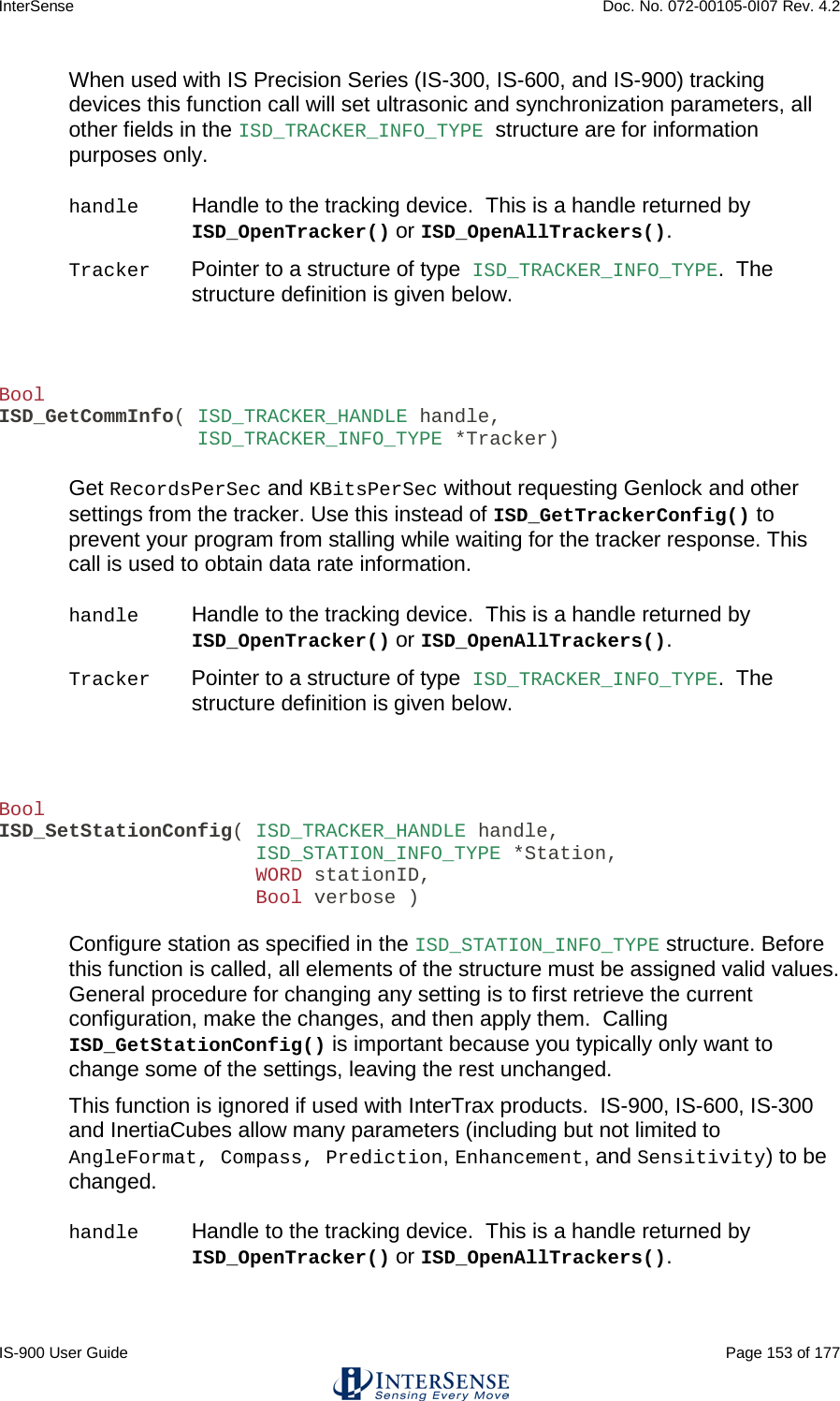
![InterSense Doc. No. 072-00105-0I07 Rev. 4.2 IS-900 User Guide Page 67 of 177 Output record mode F Put in ASCII output mode f Put in Binary output mode. Default F Output record list settings O{stationNum},[p1],[p2],[p3],.....,[pn]<> Sets the output data list for stationNum. If optional parameters are omitted, a data record containing current output list settings for the station is returned. Item Description Output Format 0 ASCII space character 1 ASCII byte 1 ASCII CR, LF pair 2 ASCII bytes 2 x, y, z position coordinates 3 floats 4 yaw, pitch, roll Euler angles 3 floats 5 X-axis direction cosines 3 floats 6 Y-axis direction cosines 3 floats 7 Z-axis direction cosines 3 floats 11 orientation quaternion 4 floats 16 stylus switch status (always 0) 1 byte (ASCII/binary) 18 x, y, z in 16 bit binary format see below 19 yaw, pitch and roll in 16 bit binary format see below 20 quaternion in 16 bit binary format see below 21 time stamp, in selected time units see section 5.3.1 22 buttons see below 23 joystick see below 40 tracking status 0-255 68 – 71 auxiliary inputs 75 communication integrity 0-100 76 Measurement quality 0-100 Default 2,4,1 Data Item 4 – Euler Angles. The Euler angles are defined as rotations about Z, then Y, then X in body frame. Angles are returned in degrees](https://usermanual.wiki/Thales-Visionix/9SMLW/User-Guide-2168100-Page-67.png)
![InterSense Doc. No. 072-00105-0I07 Rev. 4.2 IS-900 User Guide Page 68 of 177 Data Items 5, 6, 7 – Direction Cosines. X-axis, Y-axis and Z-axis direction cosines can be used to construct a 3x3 rotation matrix. X direction cosines. Y direction cosines. Z direction cosines. This matrix can also be constructed from Euler angles: Data Item 11 – Orientation Quaternion. Quaternion is returned as q = [w, x, y, z]. Quaternion to rotation matrix conversion can be accomplished using the following formula: x1 x2 x3 y1 y2 y3 z1 z2 z3 1–2y2 – 2z2 2xy – 2wz 2xz + 2wy 2xy + 2wz 1 – 2x2 – 2z2 2yz – 2wx 2xz – 2wy 2yz + 2wx 1 – 2x2 – 2y2 cos(P)*cos(Y) sin(R)*sin(P)*cos(Y) - cos(R)*sin(Y) cos(R)*sin(P)*cos(Y) + sin(R)*sin(Y) cos(P)*sin(Y) sin(R)*sin(P)*sin(Y) + cos(R)*cos(Y) cos(R)*sin(P)*sin(Y) - sin(R)*cos(Y) -sin(P) cos(P)*sin(R) cos(P)*cos(R) Yaw Roll Pitch X Y Z](https://usermanual.wiki/Thales-Visionix/9SMLW/User-Guide-2168100-Page-68.png)
![InterSense Doc. No. 072-00105-0I07 Rev. 4.2 IS-900 User Guide Page 69 of 177 Data Items 18, 19, 20 – 16 bit binary format. 16 bit binary format can be used in applications requiring fastest possible serial I/O. Each floating point number is stored in 2 bytes with only 14 bits containing actual data. This results in lower accuracy than the standard IEEE floating point format. Data is 2’s-complement. The first byte of the data set has its high-order bit set to 1; all others have them set to zero. This can be used for data synchronization. Data is returned low-order byte, then high-order byte. Use following code sample as an example on how to decode this format: To decode position: lo = (dataRecord[3] & 0x007F); hi = (dataRecord[4] & 0x007F); int14bit = (lo « 2) | (hi « 9); result = (float) int14bit * 3.0 / 32768.0; Result is a number representing position (in meters) and has a full range of ± 3.0 meters (−300.0 to+299.963 centimeters or –118.110 to 118.096 inches). To decode Euler angles: lo = (dataRecord[3] & 0x007F); hi = (dataRecord[4] & 0x007F); int14bit = (lo « 2) | (hi « 9); result = (float) int14bit * 180.0 / 32768.0; Resulting number represents orientation and has a full range of ± 180.0 (−180.0 to +179.978) degrees. To decode Orientation Quaternion: lo = (dataRecord[3] & 0x007F); hi = (dataRecord[4] & 0x007F); int14bit = (lo « 2) | (hi « 9); result = (float) int14bit * 1.0 / 32768.0; Resulting quaternion value has range of ± 1.0.](https://usermanual.wiki/Thales-Visionix/9SMLW/User-Guide-2168100-Page-69.png)
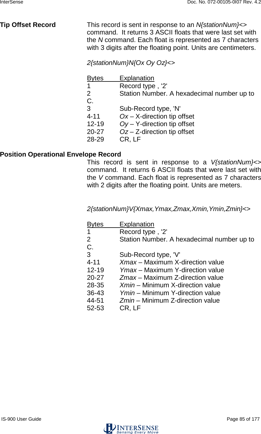
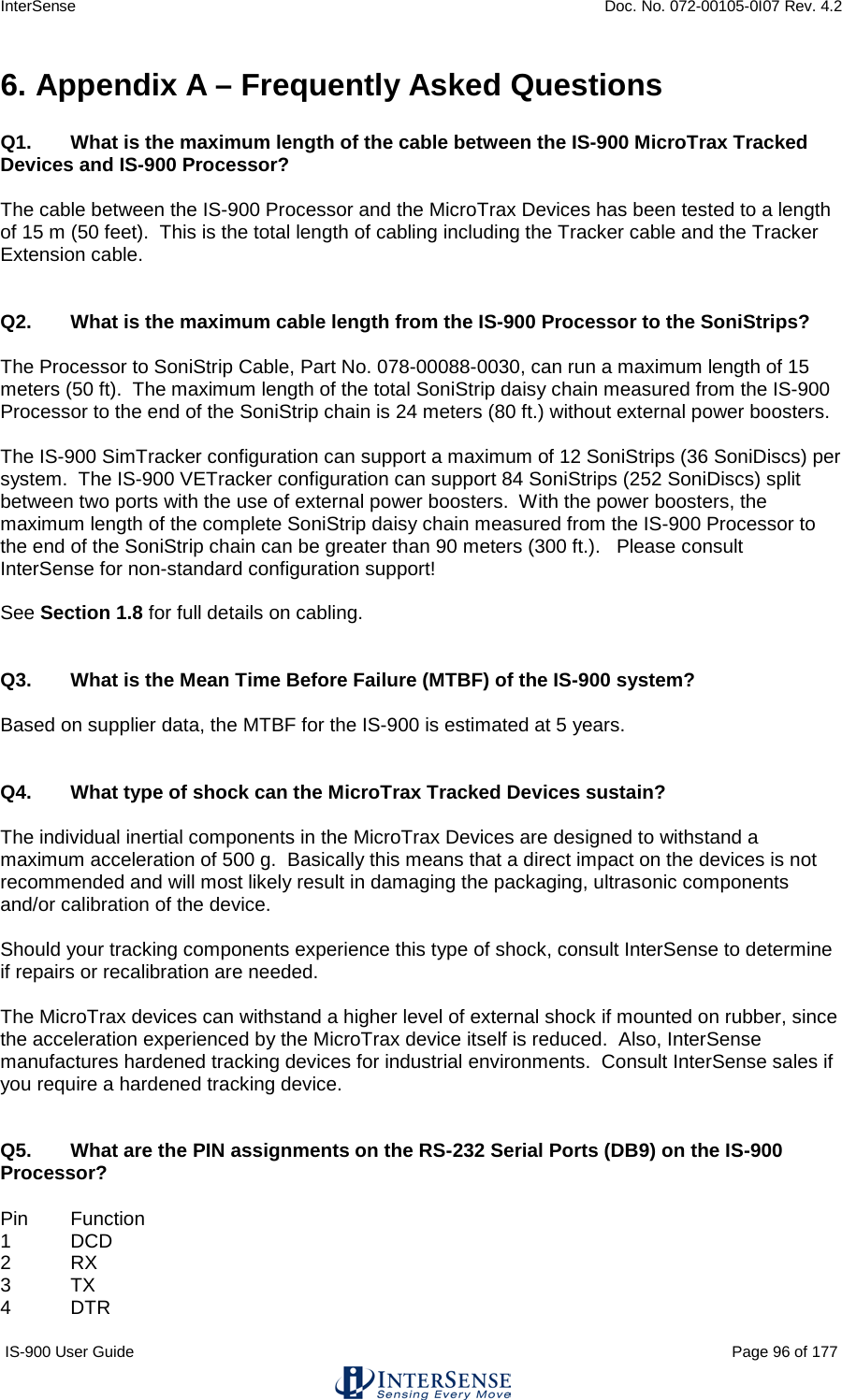
![InterSense Doc. No. 072-00105-0I07 Rev. 4.2 IS-900 User Guide Page 70 of 177 Data Item 22 – Buttons. One 3-digit integer in ASCII format or one byte in binary format. Bits represent the button states of a station’s buttons. If a button is pressed, the corresponding bit is 1 otherwise it is 0. The bit assignments for the wand are (where bit 0 is the least significant bit): Bit Button MicroTrax Wand button 0 1 1 on wand image 1 2 2 on wand image 2 3 3 on wand image 3 4 4 on wand image 4 5 center (press joystick) 5 6 trigger Data Item 23 – Joystick. Two integers, one for each axis, values ranging from 0 to 255. Two 3-digit integers in ASCII format or two 1-byte unsigned values in binary format. Values at limits and at center are: Axis Position Value left/right (1st integer) left 0 center 127 right 255 front/rear (2nd integer) rear 0 center 127 front 255 Define Tip Offsets N{stationNum},[Ox, Oy, Oz]<> By default, the point being tracked is for each station is: Wand Station: Tip. Head Tracker Station: Intersection of front surface, bottom surface and at mid length, see image to the left. Hand Tracker Station: center top, in dent. This command allows the user to define a set of position offsets, so a different point can be tracked. Offsets are measured in the body coordinate frame of the MicroTrax station and are entered in centimeters. If optional parameters are omitted, current settings are returned. Default 0,0,0 Tip Offset: intersection of front surface and bottom surface and at mid length.](https://usermanual.wiki/Thales-Visionix/9SMLW/User-Guide-2168100-Page-70.png)
![InterSense Doc. No. 072-00105-0I07 Rev. 4.2 IS-900 User Guide Page 71 of 177 Position Operational Envelope V{stationNum},[Xmax, Ymax, Zmax, Xmin, Ymin, Zmin]<> This command sets the boundaries of the area where position is to be tracked. Whenever a station leaves the defined range, position tracking is stopped and only resumed once it is back within the defined boundaries. Parameters are entered in meters. If optional parameters are omitted, current settings are returned. Units are meters. Default 200,200,200,-200,-200,-200 4.3. Fastrak™ Commands Implemented for Compatibility Hemisphere H{stationNum},[p1,p2,p3]<> Sets the tracking hemisphere for a magnetic tracking system. Because InterSense trackers are not magnetic the parameters are ignored. However, they can be set and then queried for compatibility with software such as MultiGen SmartScene or Immersion Corporation haptic Software. If optional parameters are omitted, a data record containing current Hemisphere settings for the station is returned. Default 1,0,0 4.4. InterSense specific Commands All InterSense specific commands start with the letter M (for “Manufacturer-specific”) and must be completed by a CR,LF pair.](https://usermanual.wiki/Thales-Visionix/9SMLW/User-Guide-2168100-Page-71.png)
![InterSense Doc. No. 072-00105-0I07 Rev. 4.2 IS-900 User Guide Page 72 of 177 4.4.1. System Configuration Commands Time Units The time stamp recorded is the time when the tracker data was collected from the hardware. The time index is set to zero when tracker is first turned on. MT<> Sets the units for the data record time stamp to milliseconds. Mt<> Sets the units for the data record time stamp to microseconds. Default T Set Current Time to Zero MZ<> This command sets current time index of the tracker to zero. Set Ethernet Communication Parameters MEthIp{address}<> Sets System IP address. Use dotted format like 192.168.1.1. If address is omitted, the current address is returned, 31EI[address]<>. The IP address takes effect immediately unless an address was already set, in which case system settings must be saved and the system must be restarted. MEthTcpPort{port}<> Sets TCP communication port. MEthUdp{state}<> Sets state of UDP broadcast. 1=enabled, 0=disabled MEthUdpPort{port}<> Sets UDP broadcast port. MEthSubnet{subnet}<> Sets network subnet. MEthMode{mode}<> Sets network subnet. 2=DHCP, 1=manual, 0=disabled MEthApply<> Apply Ethernet settings (settings must be saved to make this permanent). Default Ethernet communications settings: UDP state OFF UDP port 5001 TCP port 5005 Subnet 255.255.255.0 IP address None](https://usermanual.wiki/Thales-Visionix/9SMLW/User-Guide-2168100-Page-72.png)
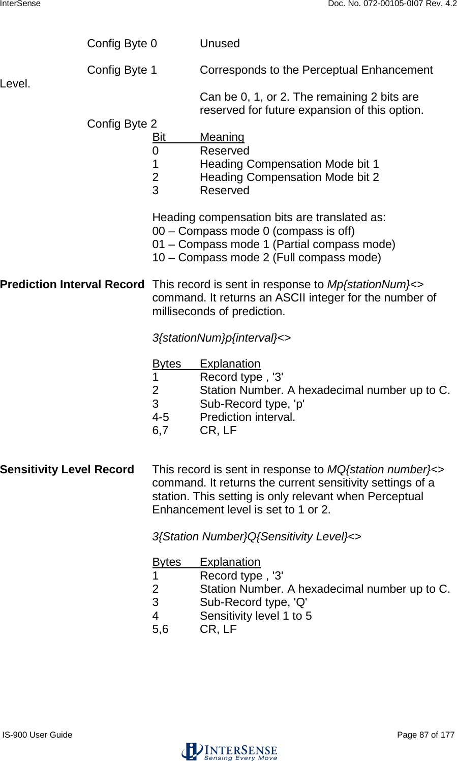
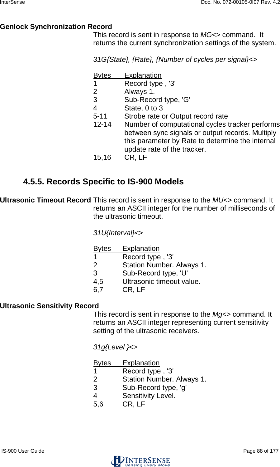
![InterSense Doc. No. 072-00105-0I07 Rev. 4.2 IS-900 User Guide Page 73 of 177 InterSense System Status Record Request MS<> Request the manufacturer-specific system status record. This is information about parameters which are specific to the InterSense product, additional to the standard system status information obtained using the S command. Tracking Status Record Request MP<> Requests tracking status information for all 12 stations. See Section 5.5.5 for the description. Ultrasonic Timeout Interval MU[interval]<> This command has no effect with the IS-900. Default N/A Ultrasonic Receiver Sensitivity Mg[Level]<> This command has no effect with the IS-900. Default N/A Genlock Synchronization MG[State, Rate]<> State 0 – Genlock is off (free run) 1 – Reserved 2 – External sync, manual (supply strobe rate) 3 – Internal sync, supply output record rate Rate Value in Hertz used with State = 2 and 3 Default 0 Genlock Phase MGP[Param]<> Param can be the Phase (0 to 100%) or ‘+’ to increase to the next phase point, or ‘-‘ to decrease to the next phase point. Please see Appendix F for complete details. Default 0 Genlock Sync Source MGS[source]<> source 1 – TTL 2 – NTSC](https://usermanual.wiki/Thales-Visionix/9SMLW/User-Guide-2168100-Page-73.png)
![InterSense Doc. No. 072-00105-0I07 Rev. 4.2 IS-900 User Guide Page 74 of 177 Configuration Lock Configuration lock commands are used to prevent unintentional changes to tracker configuration. Two Levels of protection are provided. The First prevents changes to saved settings. The second prevents changes to current unsaved (session) settings as well as saved settings. MConfigLockMode[mode]<> Mode 0 Lock off 1 Lock saved settings 2 Lock saved and session settings Default 0 In mode 1 (lock saved settings), the Fastrak commands to save current (^K) and restore factory (W) settings are disabled. In mode 2 (lock saved and session settings), the Fastrak command to restore saved settings (^Y) is disabled as well as ^K and W. In mode 0 (lock off), ^Y, ^K and W are all enabled. When mode is changed, it is saved to nonvolatile memory without affecting any other saved settings. If mode is omitted, the current setting is returned. The LCD menu options to save and restore settings are not affected by lock mode. SoniStrip LED control ML[state]<> If state is 0, the blue LEDs on the SoniStrips are disabled. Visual confirmation of the operation of the ultrasonic system is important, so don’t disable the LEDs unless they interfere with your application. Default 1 Beacon Scheduler MSchAlg[n]<> Selects beacon Scheduling Algorithm. If n is 1, a distance-based algorithm is used. This algorithm chooses beacons based on distance only. If n is 2 a directional algorithm is used which chooses beacons based on orientation as well as distance. Default 2 Error reporting Hardware and configuration errors are stored internally and can be reported to the application. If the application is not setup to accept error messages, or if you are not sure, error reporting should be disabled. This setting is not saved with tracker configuration, so error reporting is off every time tracker is turned on.](https://usermanual.wiki/Thales-Visionix/9SMLW/User-Guide-2168100-Page-74.png)
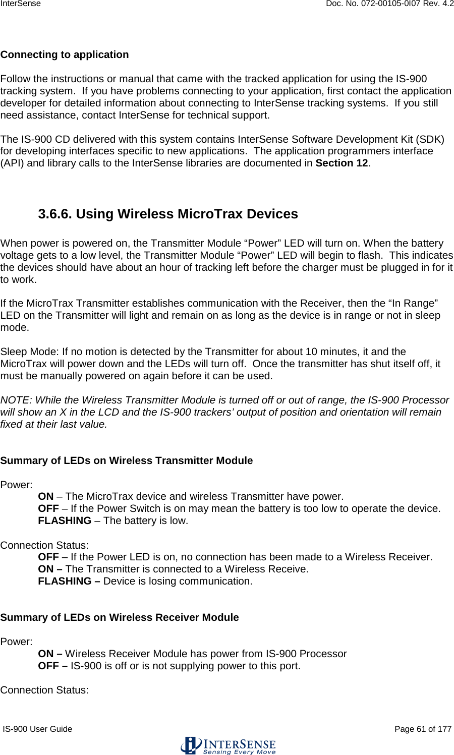
![InterSense Doc. No. 072-00105-0I07 Rev. 4.2 IS-900 User Guide Page 75 of 177 ME<> Returns all errors, one per error message. MEC<> Clear all errors from internal list. ME1<> Enable error reporting. ME0<> Disable error reporting. Default Error reporting is OFF Command logging Command logging captures all host commands into a file for debugging purposes. The log file holds a maximum of 500 kB. When the max size is reached, the file is rewound and overwritten with new entries. Long series of P and MP commands are abbreviated to save space. The command logging state is also indicated on the LCD (see Section 5). Command logging control is available on the LCD menu under System ConfigCommand Log: Enable Log, Disable Log and Clear Log. It is accessed by the following command set. MLogOpen<> Enables logging. If settings are saved, logging will remain on through reset. An existing log file is always appended to. MLogClose<> Disables logging. MLogClear<> Disables logging and deletes log file. Use MLogOpen to resume logging. MLogState<> Returns logging state (0=off, 1=on), 31LS{0,1}<> MLogSend<> Outputs log file to host one command per line. 31LF<timestamp in ms>:<command><> the timestamp is a decimal number and is not zero-padded. The log file can alternatively be retrieved using ISDEMO (see section 10). 4.4.2. InterSense-specific Station Parameters InterSense Station Status Record Request Ms{stationNum}<> Request an individual sensor status record for stationNum. This is information about parameters which are specific to the InterSense product. Prediction Interval Mp{stationNum},[Interval]<> Sets the time-interval of prediction for stationNum. Interval is an integer number of time in milliseconds. Suggested](https://usermanual.wiki/Thales-Visionix/9SMLW/User-Guide-2168100-Page-75.png)
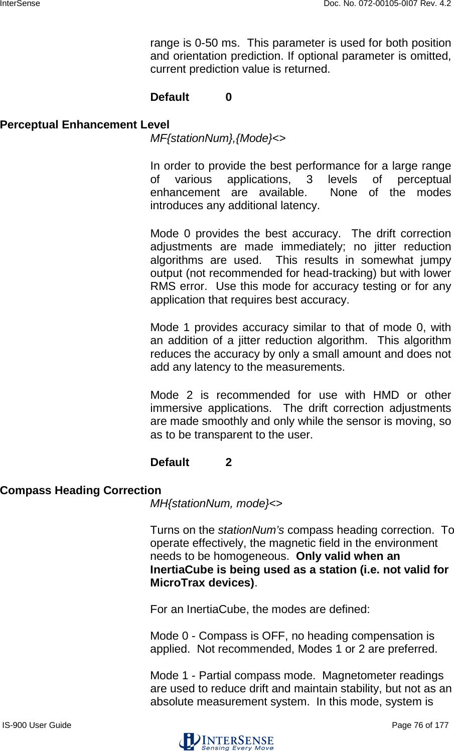
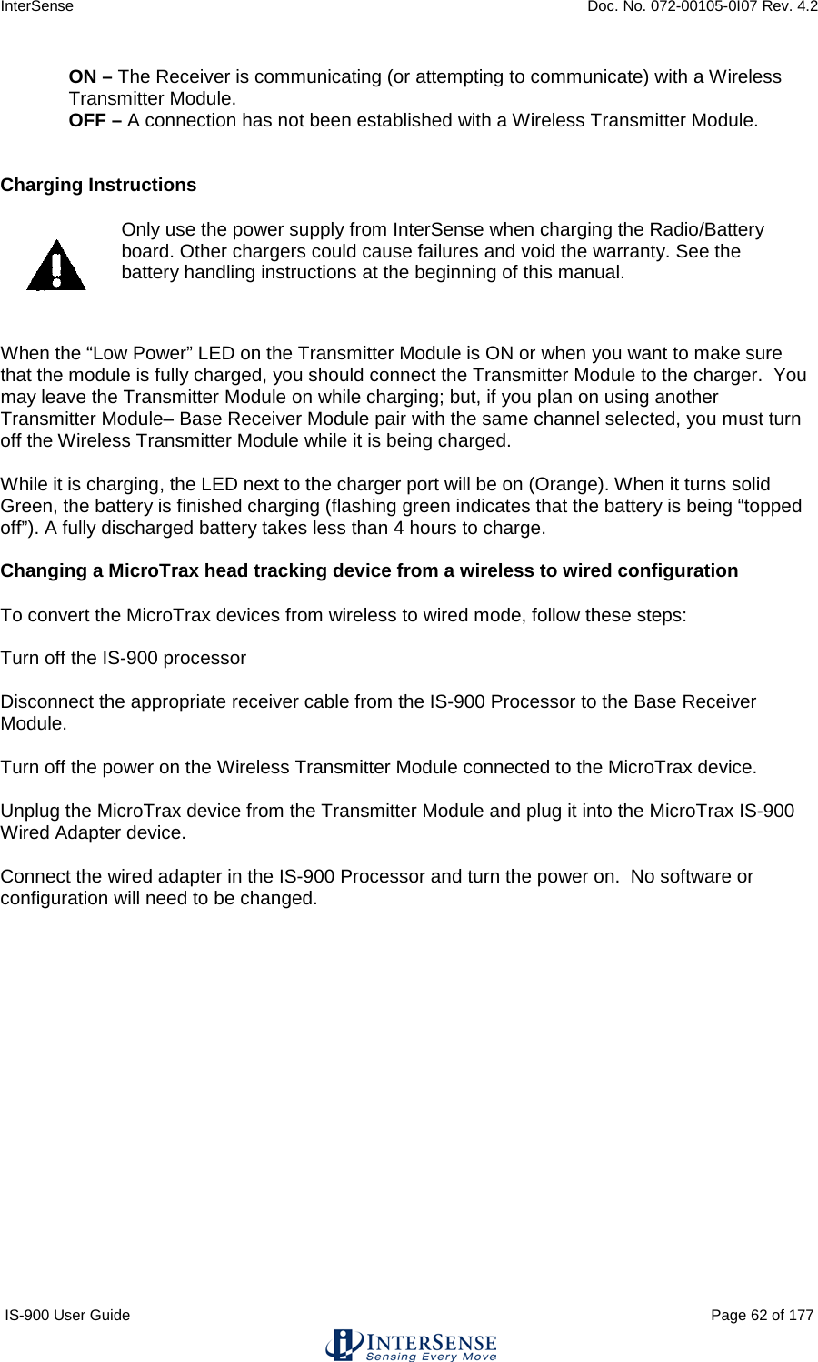
![InterSense Doc. No. 072-00105-0I07 Rev. 4.2 IS-900 User Guide Page 77 of 177 much less susceptible to magnetic interference, but heading drift will slowly accumulate. This mode is particularly useful when high rotational sensitivity settings are used. Mode 2 - FULL compass mode. Readings produced by the magnetometers inside the InertiaCube are used as the absolute reference orientation for yaw. Default 2 Mh{stationNum}<> Turns off the stationNum’s compass heading correction. There can be slow drift in the yaw direction. Only valid when an InertiaCube is being used as a station (i.e. not valid for MicroTrax devices). Rotational Sensitivity Level MQ{stationNum},[Sensitivity Level]<> Adjusts rotational sensitivity of a station when the Perceptual Enhancement Level is set to level 2. Sensitivity Level is an integer 1 to 4 where 1 is the lowest and 4 is the highest sensitivity. It is recommended that sensitivity be set to 4 when enhancement is set to level 1. If optional parameter is omitted, current value is returned. Default 3 4.4.3. Station and Constellation Configuration Commands This section describes the commands used to assign sensing devices to the logical components of the tracking system. Such devices with the IS-900 are SoniStrips and the SoniDiscs (beacons) that make up the Constellation Array. All commands in this section start with MC. A Configuration Session is the period during which MC commands are received and accepted. It starts when the first MC command arrives and ends when these commands are explicitly activated with the MCe<> (or discarded with the MCx<>) command. Associate Fixed PSE with a Constellation MCF{FPSE number},{xp, yp, zp, xn, yn, zn, IDcode}<> Configures or adds a Fixed PSE. For IS-900 FPSE is a SoniDisc ultrasonic transponder beacon. If only the FPSE number parameter is present then current data for that PSE is returned on the serial port. If that PSE is not configured, record will contain Hardware ID of -1. If no parameters are provided then data for all configured Fixed PSEs is returned, each PSE in a separate record. This command does not take effect until explicitly activated by the MCe<> command. FPSE number](https://usermanual.wiki/Thales-Visionix/9SMLW/User-Guide-2168100-Page-77.png)
![InterSense Doc. No. 072-00105-0I07 Rev. 4.2 IS-900 User Guide Page 78 of 177 A Unique number identifying a Fixed PSE (beacon) within a Constellation (a complete set of fixed PSEs). Numbering starts at 1. xp, yp, zp FPSE position in meters. xn, yn, zn Normal vector. IDcode Hardware ID of the PSE. <> CR LF pair. Disassociate Fixed PSE from the Constellation MCf[Fixed PSE number, IDcode]<> If PSE number and IDcode are not associated in the current configuration, this command is ignored. This command does not take effect until explicitly activated by the MCe<> command. Clear All Fixed PSEs (Constellation) Command MCC<> Delete all Fixed PSEs from the configuration. This command does not take effect until explicitly activated by the MCe<> command.](https://usermanual.wiki/Thales-Visionix/9SMLW/User-Guide-2168100-Page-78.png)
![InterSense Doc. No. 072-00105-0I07 Rev. 4.2 IS-900 User Guide Page 80 of 177 4.5. Records Returned from the Tracker to the Host 4.5.1. Format Considerations Record Headers The first byte of each record is used to identify its type. 0 – Data record. 2 – Fastrak™ status record. 3 – InterSense manufacturer-specific status record. Floating Point Numbers Floating point numbers can be returned as IEEE 32 bit floats or as ASCII numbers in X.xf notation, where: X is the total number of characters used to represent the float. x is the number of digits after the floating point. f is a symbol indicating that number is a float. For example, number -42.6 in 10.4f format would look as follows: “-42.6000” 4.5.2. Status Record Hexadecimal Character Decoding System Status, Manufacturer Status, and Manufacturer Station records use Hexadecimal Characters to encode status data. Each character can be 0 to F and can encode 4 bits. Logical AND operator can be used to test specific bits. Please see following code example: unsigned short byte1, byte2, byte3; char hexChar[2]; hexChar[1] = 0x00; hexChar[0] = statusRecordBuffer[3]; sscanf(hexChar,"%x", &byte1); hexChar[0] = statusRecordBuffer[4]; sscanf(hexChar,"%x", &byte2); hexChar[0] = statusRecordBuffer[5]; sscanf(hexChar,"%x", &byte3);](https://usermanual.wiki/Thales-Visionix/9SMLW/User-Guide-2168100-Page-80.png)
![InterSense Doc. No. 072-00105-0I07 Rev. 4.2 IS-900 User Guide Page 89 of 177 Fixed PSE Record This record is sent in response to MCF[Fixed PSE number]<> command. It returns the current settings of a single PSE or entire Constellation. 31F{Fixed PSE number}{Fixed PSE record}<> Bytes Explanation 1 Record type , '3' 2 Constellation Number. Always '1' 3 Sub-Record type, 'M' 4-10 Fixed PSE number in ASCII decimal format. 11-40 x, y, z components of position vector in 10.4f ASCII format. Values are in meters. 41-61 x, y, z components of normal vector in 7.2f ASCII format 62-68 Hardware ID code in ASCII format. 69,70 CR, LF Tracking Status Record Sent in response to MP<> command. It returns the tracking status information for all 12 stations. Range measurement is defined as an ultrasonic signal received by a single URM. For example, if the system is configured with two URMs and six ultrasonic beacons (SoniDiscs), 12 range measurements per cycle could be received. 31P{Tracking state record}<> Bytes Explanation 1 Record type, 3'3' 2 Station Number. Always 1. 3 Sub-Record type, 'P' 4 Tracking state identifier for station 1. State can be L if lost, T for tracking, or X for invalid. Please see Section 4.2.10 of this manual for complete description. 5 Number of range measurements received this cycle. 6 Number of range measurements rejected. . … 3+3*N Tracking state identifier for station N. . … 40-44 Update rate per station. 45 Not used, always blank. 46 Genlock identifier. Can be G for Genlock on and synchronized, X if Genlock on but not synchronized, or blank if Genlock is off. 47,48 CR, LF](https://usermanual.wiki/Thales-Visionix/9SMLW/User-Guide-2168100-Page-89.png)
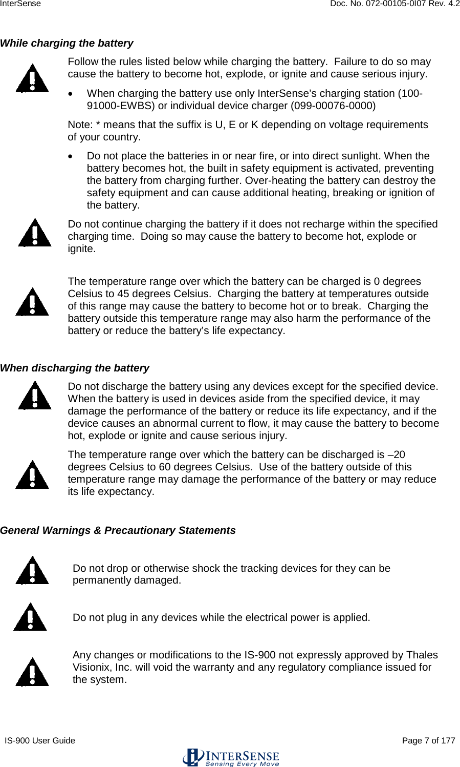
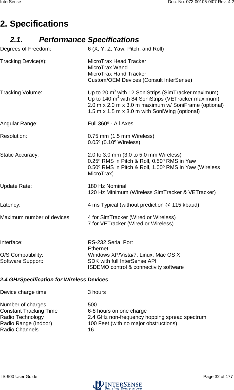
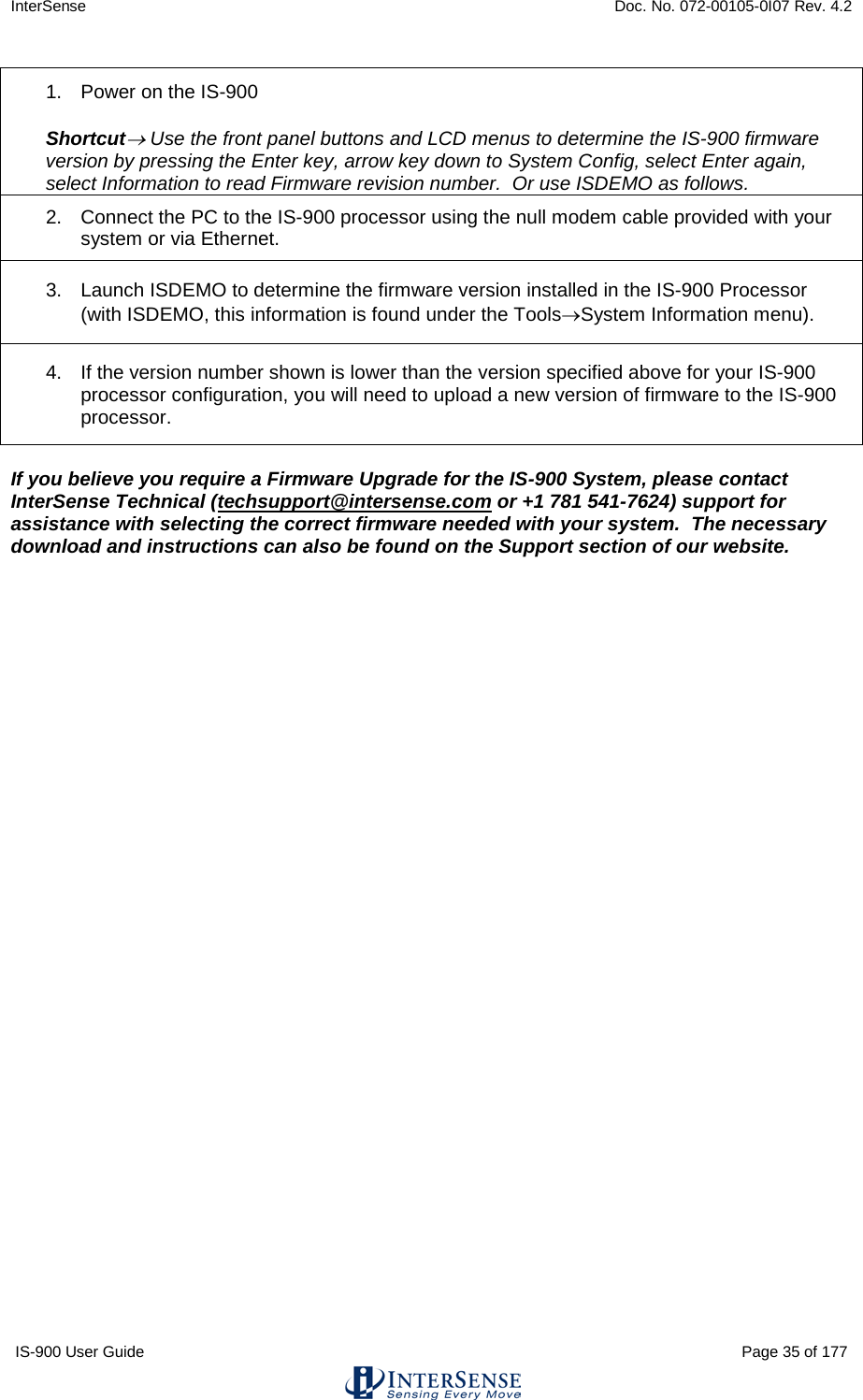
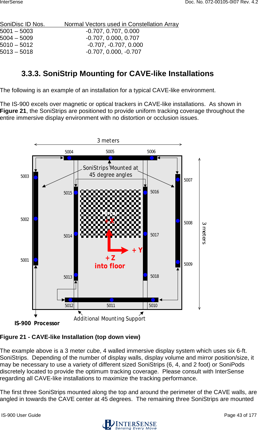
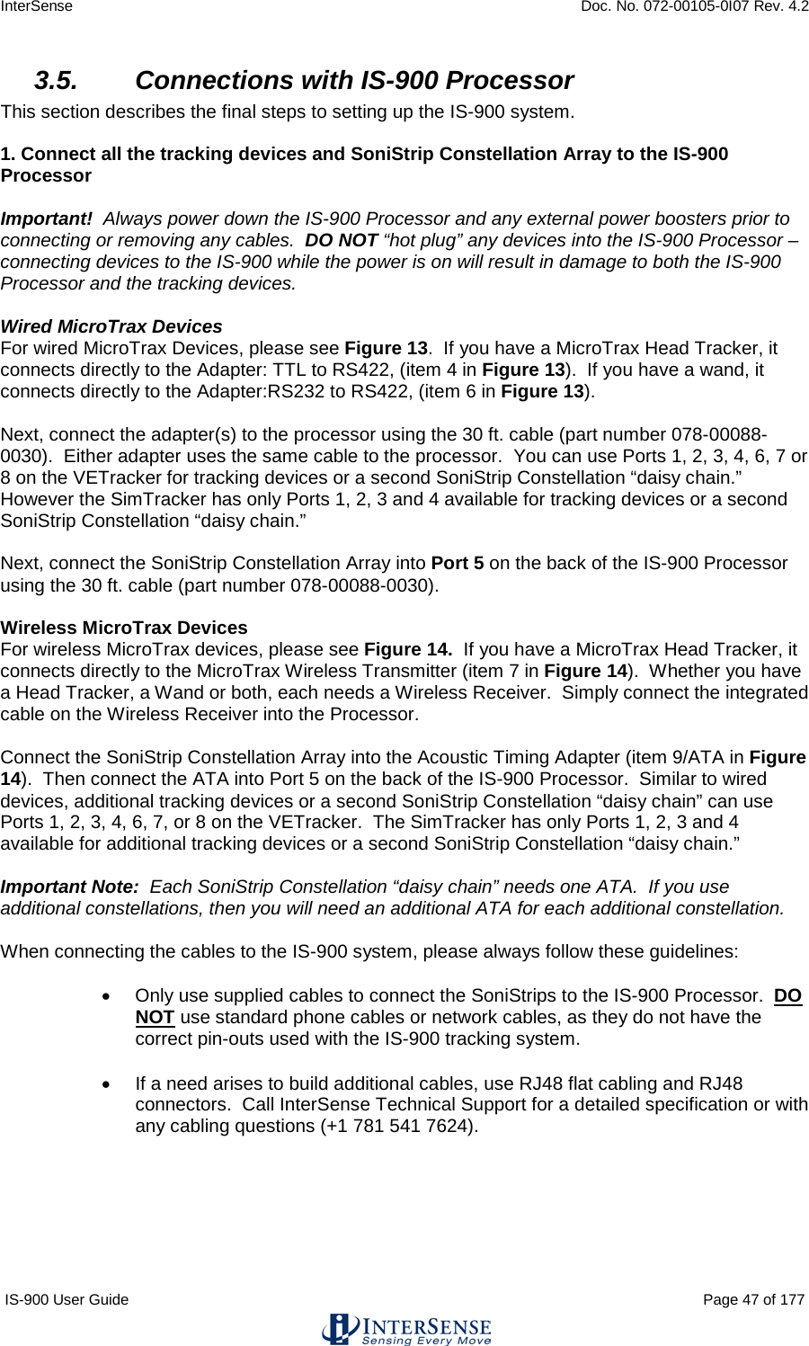
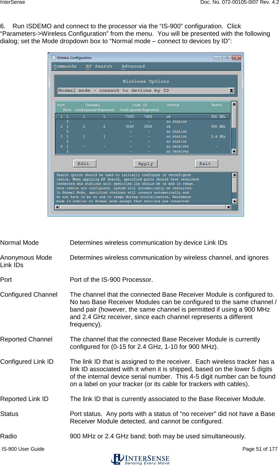
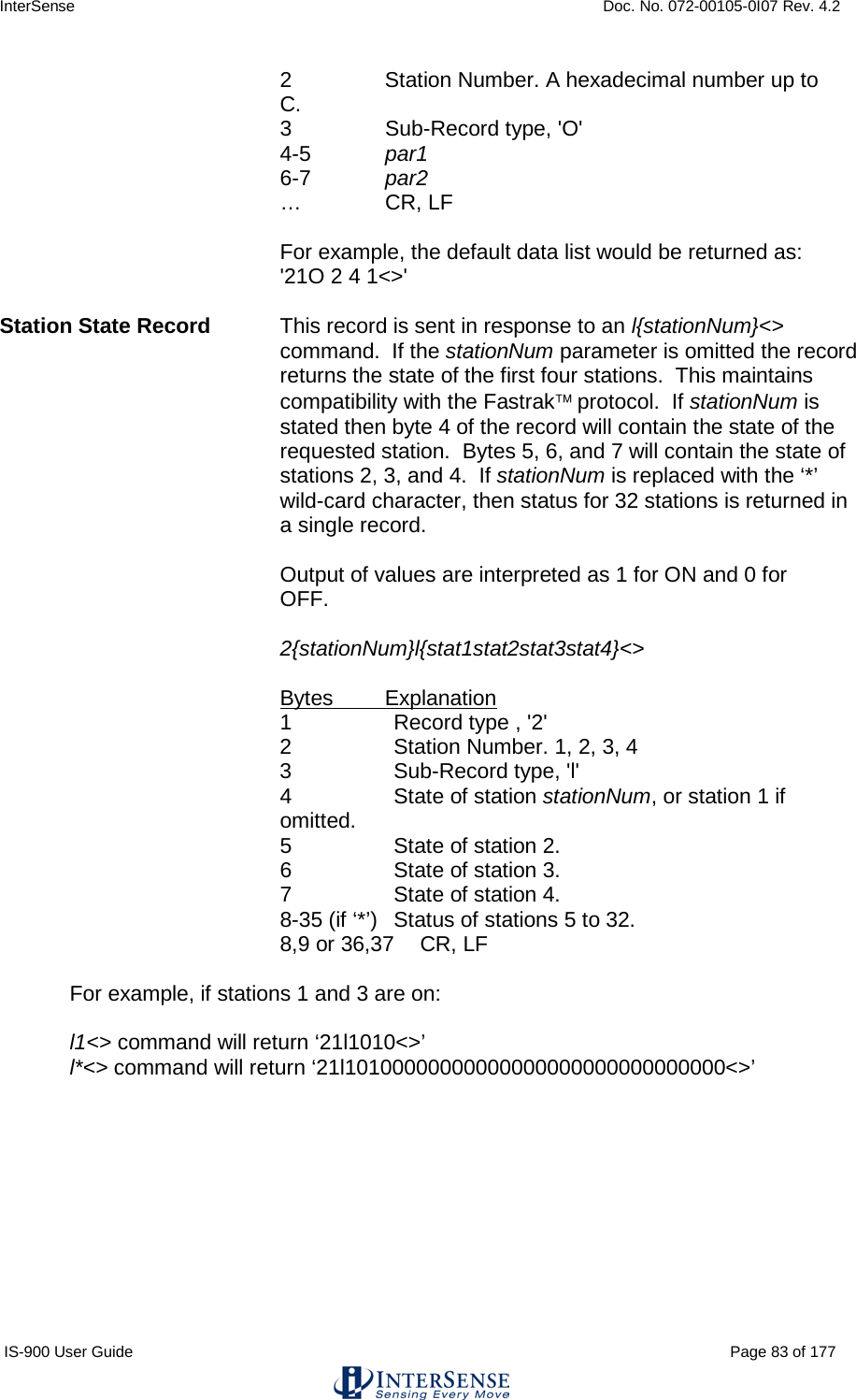
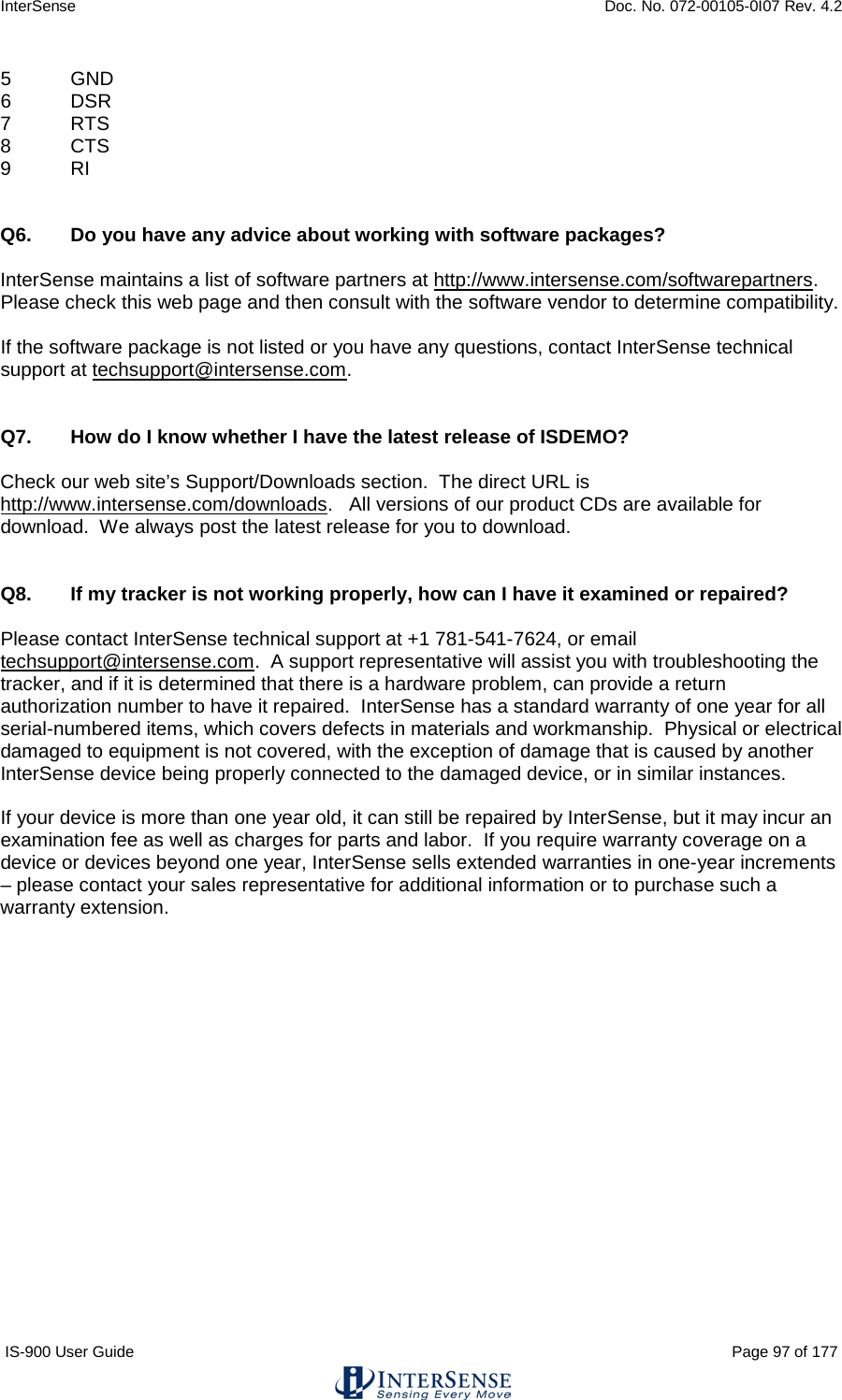
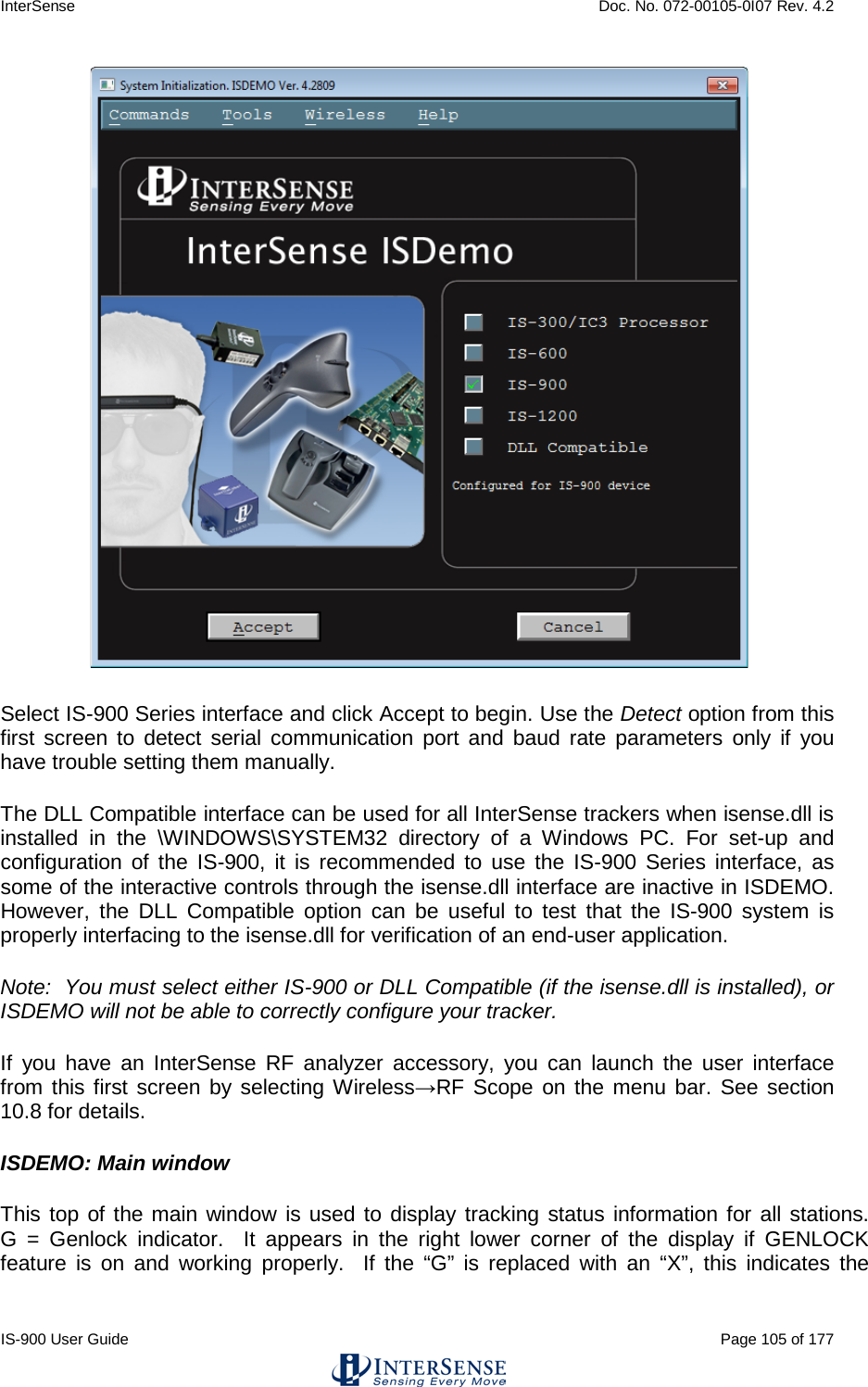
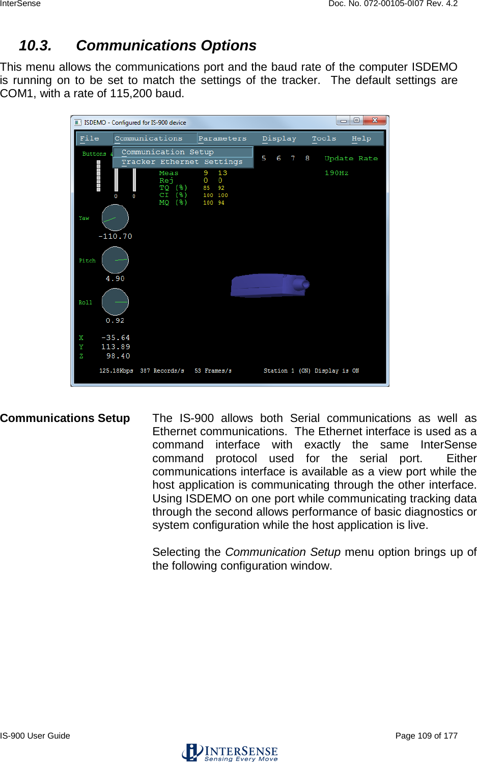
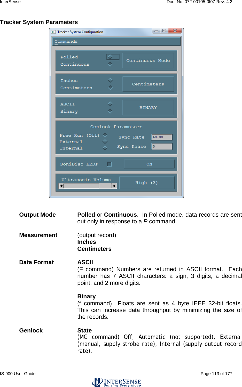
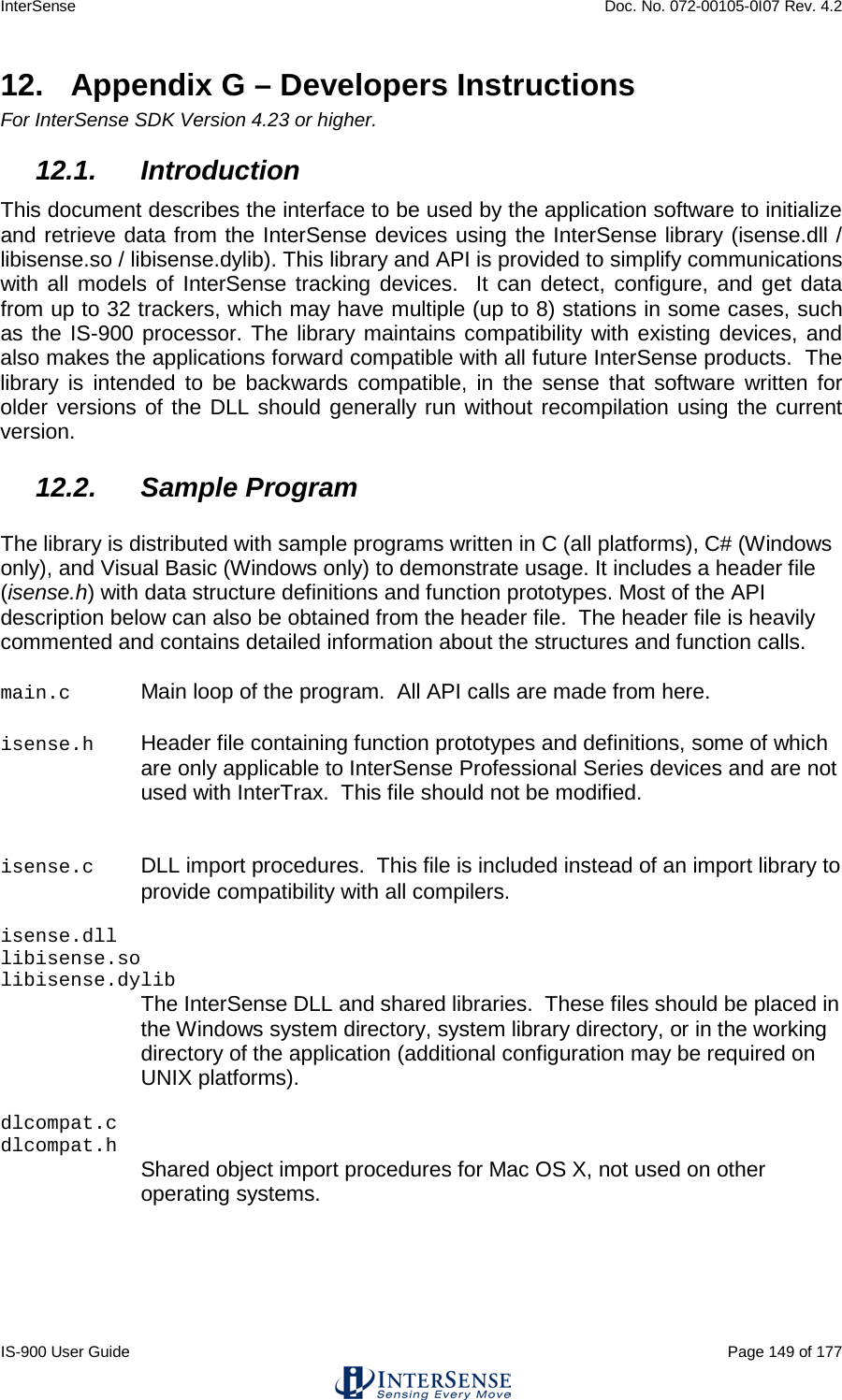
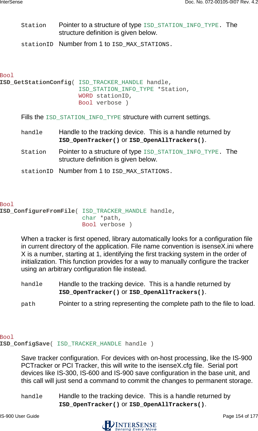
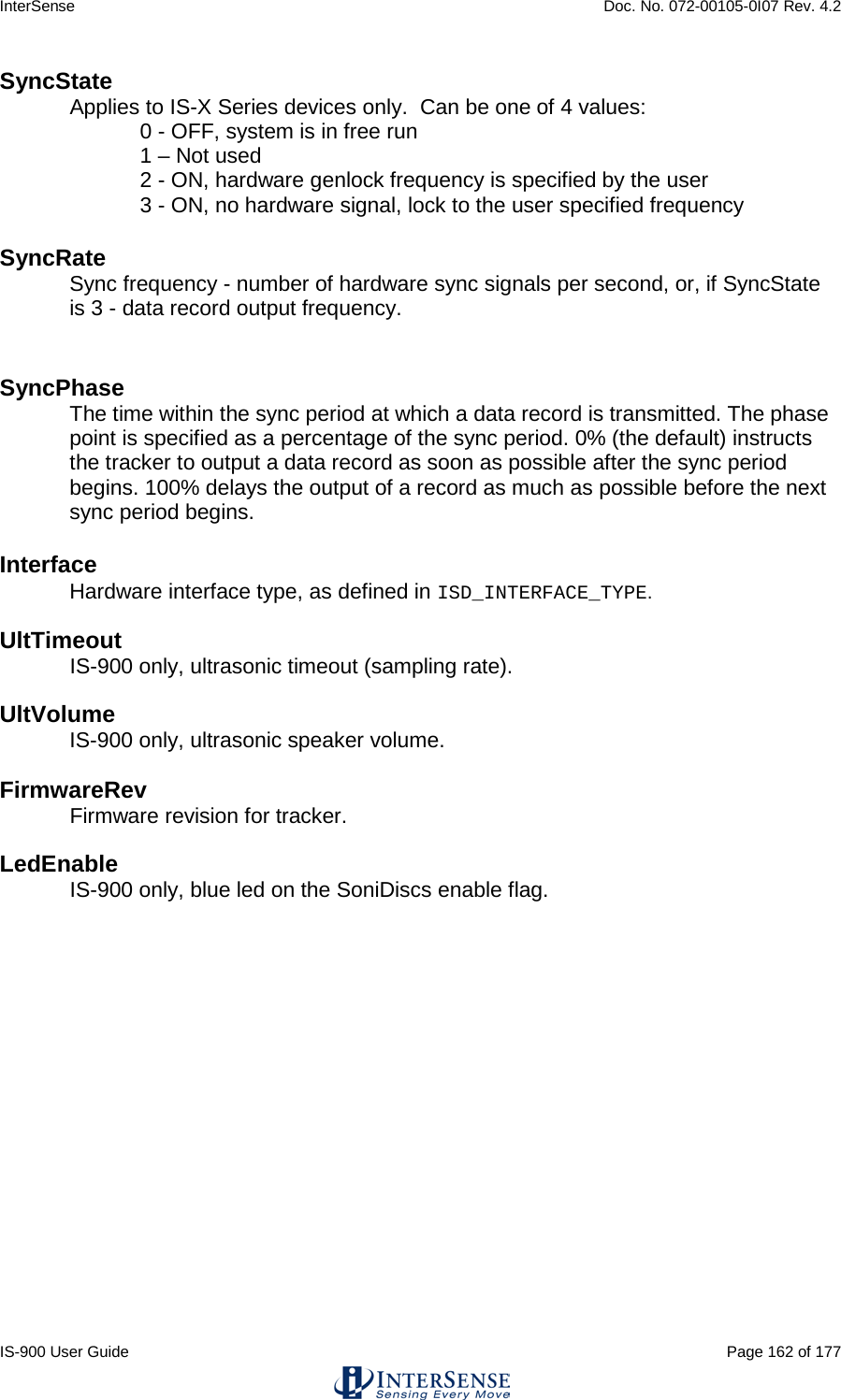
![InterSense Doc. No. 072-00105-0I07 Rev. 4.2 IS-900 User Guide Page 95 of 177 5.3. IS-900 LCD Menu Flow Chart Figure 41 illustrates the flow chart for the IS-900 LCD menu. LCD menu flow chart for firmware versions 4.29 and greater.Bold boxes represent decision points. Communication Station Config System Config Errors Display Reset Encoders (reserved) Exit Menu Baud Rate Data Output Ethernet BACK 0. 9600 Baud 1. 19200 Baud 2. 38400 Baud 3. 115200 Baud BACK Binary Form ASCII Form BACK Inches Centimeters BACK Polled Continuous BACK Format Units Sample Mode BACK Set Station Config Station View Station BACK Information Settings Genlock Beacons Command Log Monitor BACK Set Station XX # Prediction Sensitivity Enhancement Compass State BACK View Errors Clear Errors BACK 0. Off 1. Bias 2. Full BACK 0. None 1. Partial 2. Full BACK Station On Station Off BACK 1. Low 2. Medium 3. High 4. Max BACK Prediction: XXms Errors #x xxxxxxH Station [X] State [X] Enhancement [X] Sensitivity [X] Compass [X] Prediction [X] BACK Set Group XX # Phase Point xxx % Output Rate xxx Hz Strobe Rate xxx Hz Rate: xxxx Hz Update Rate Rev. _____ BACK Save Current Restore Factory Restore Saved Set Config Lock BACK State Phase Source BACK Set Phase Increase Decrease BACK Genlock Off External Internal BACK 0. Off 1. Saved 2. Saved/Session BACK LED Control Volume BACK Set Group Set Mode BACK Meas Received Meas Rejected Comm Integrity Track Quality Meas Quality BACK Enable Log Disable Log Clear Log BACK Broadcast On Broadcast Off UDP Port BACK UDP Port: xxxx TTL NTSC BACK Mode IP Address Subnet Mask TCP Port Apply UDP Broadcast BACK 0. Disabled 1. Manual 2. DHCP BACK IP Address xxx.xxx.xxx.xxx Subnet Mask xxx.xxx.xxx.xxx TCP Port xxxx LEDs On LEDs Off BACK Min Low Med Max BACK Figure 41 - IS-900 LCD Menu Flow Chart](https://usermanual.wiki/Thales-Visionix/9SMLW/User-Guide-2168100-Page-95.png)
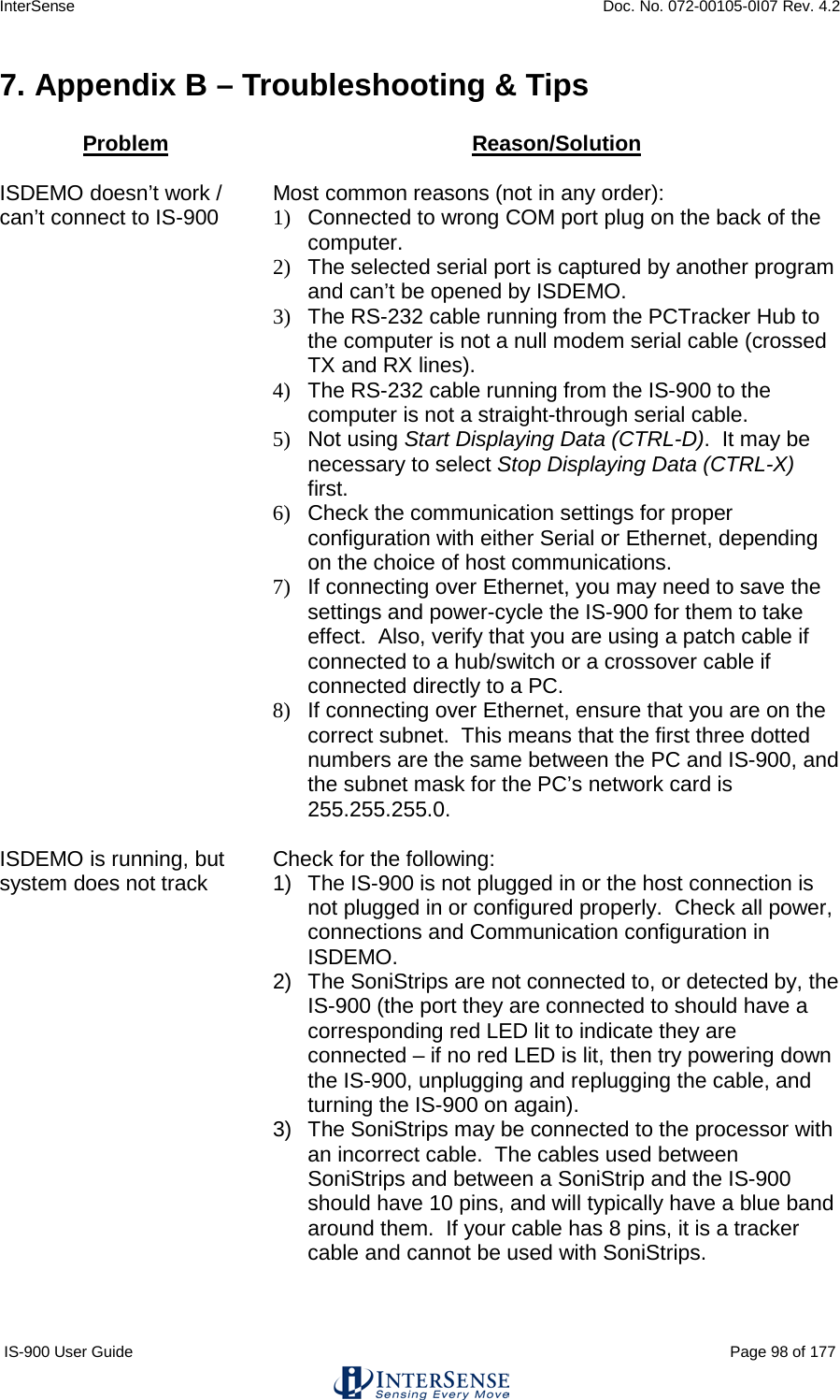
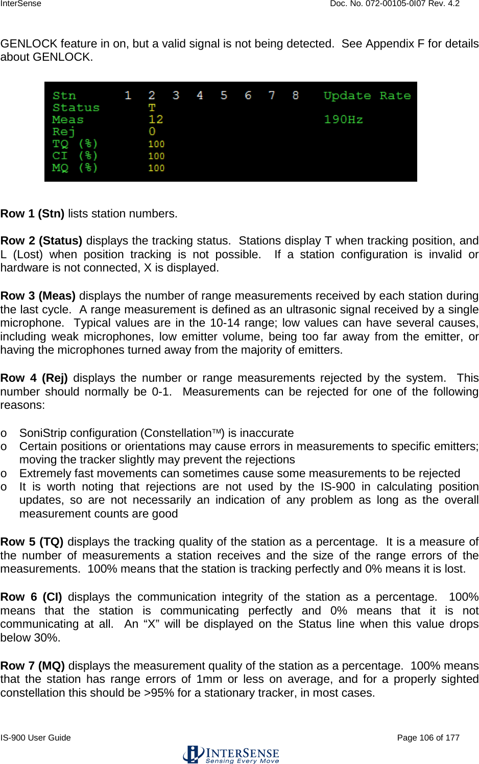
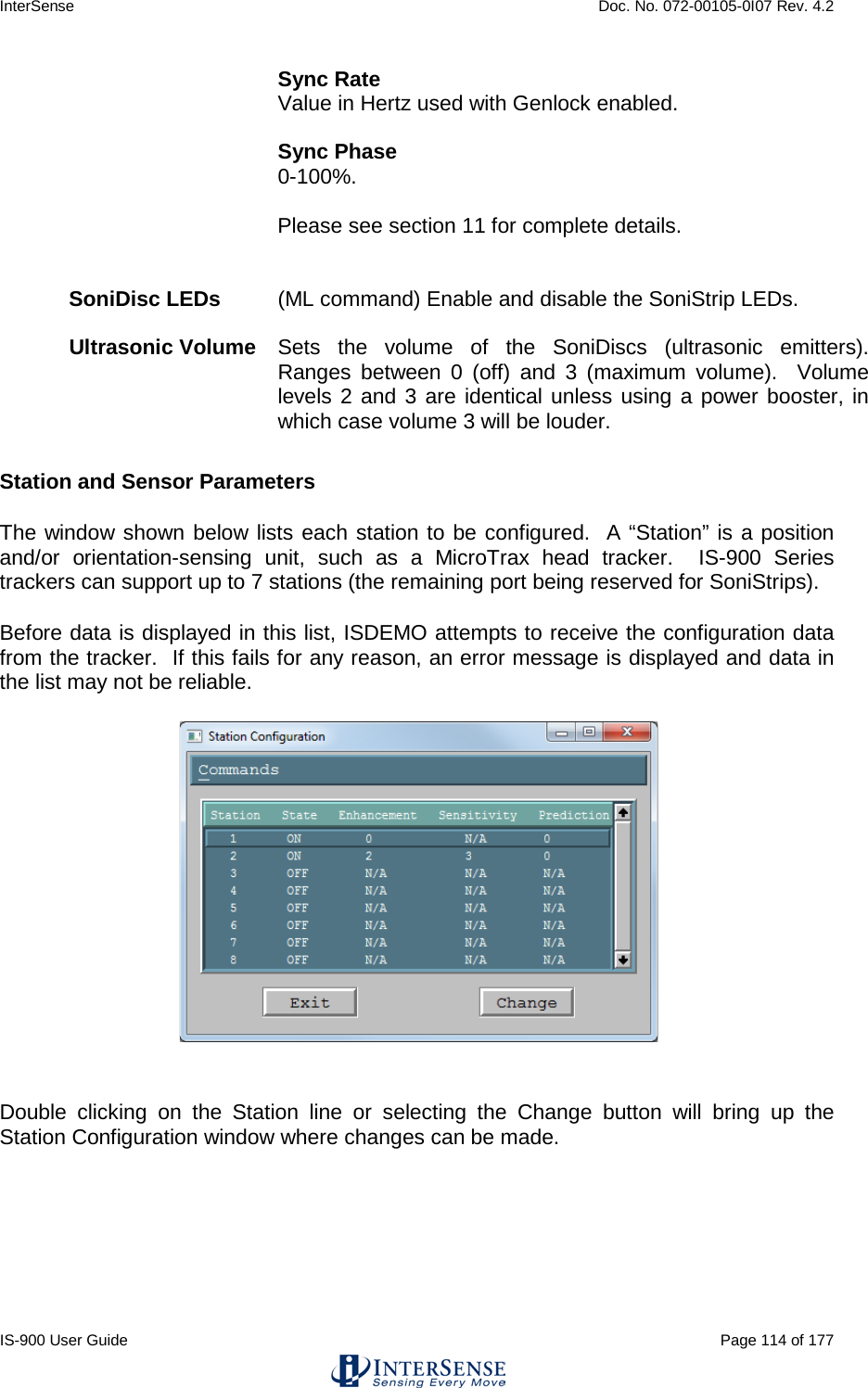

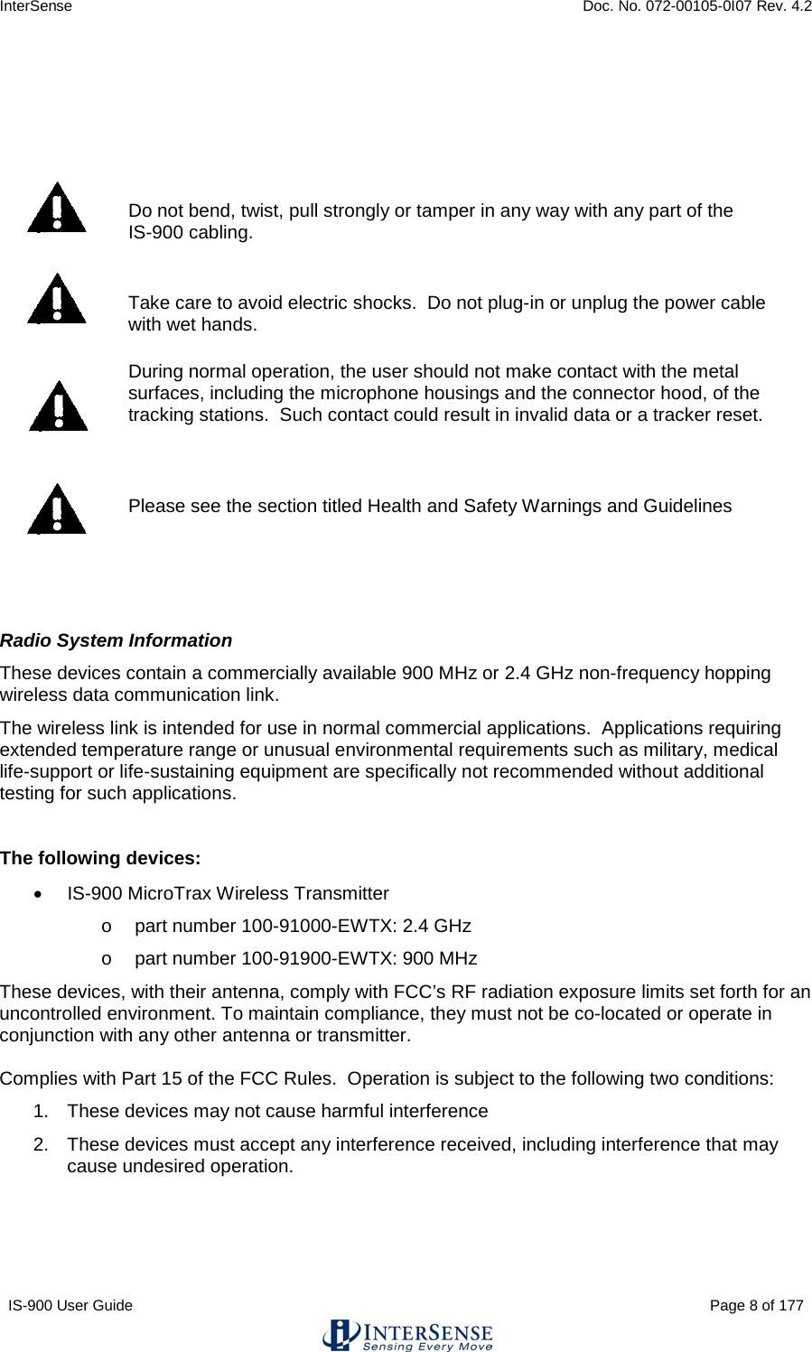
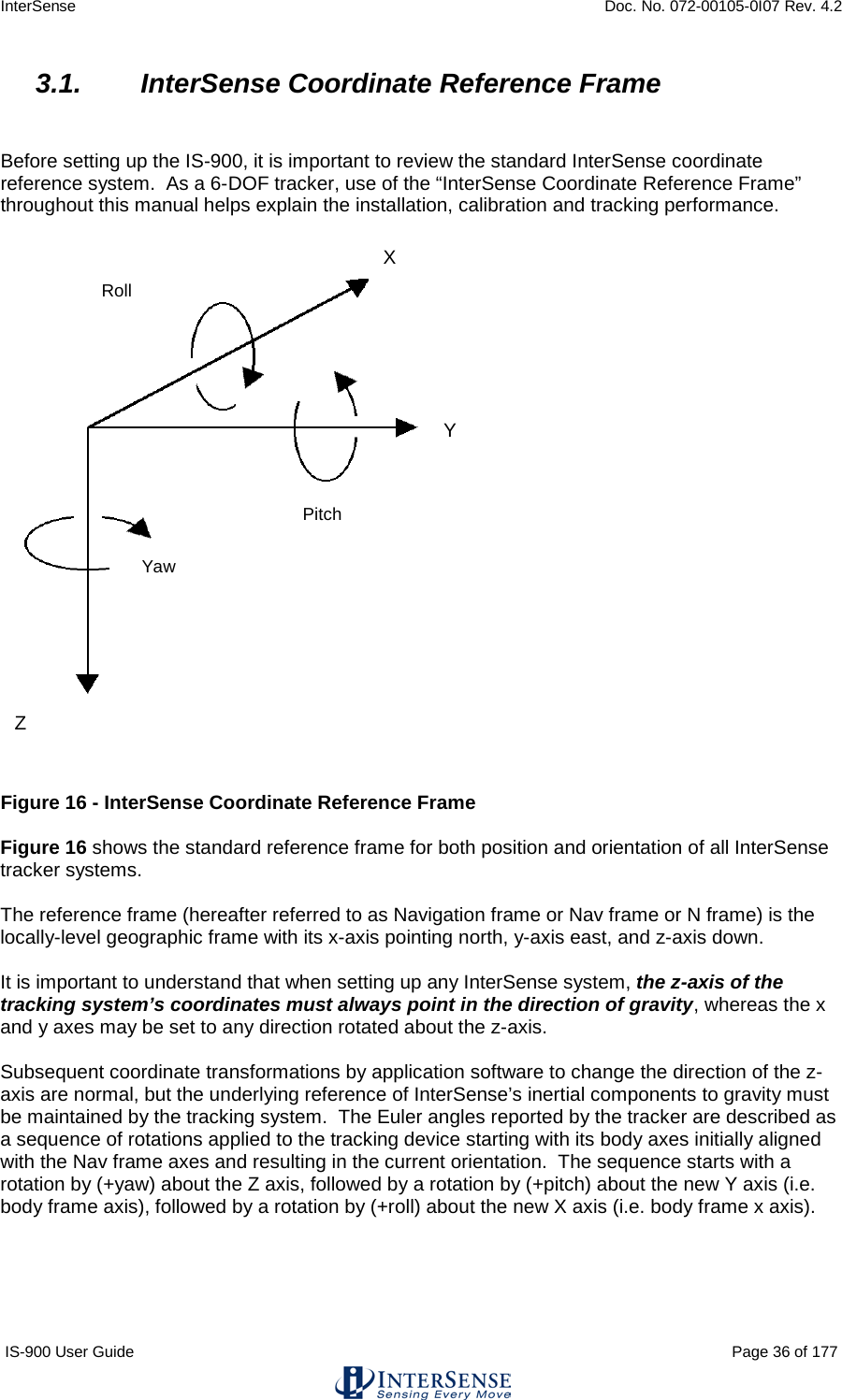
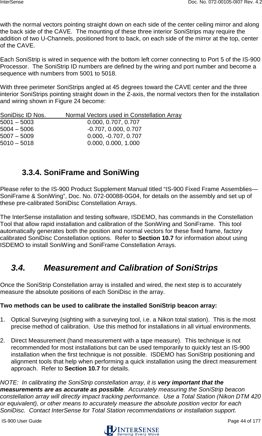
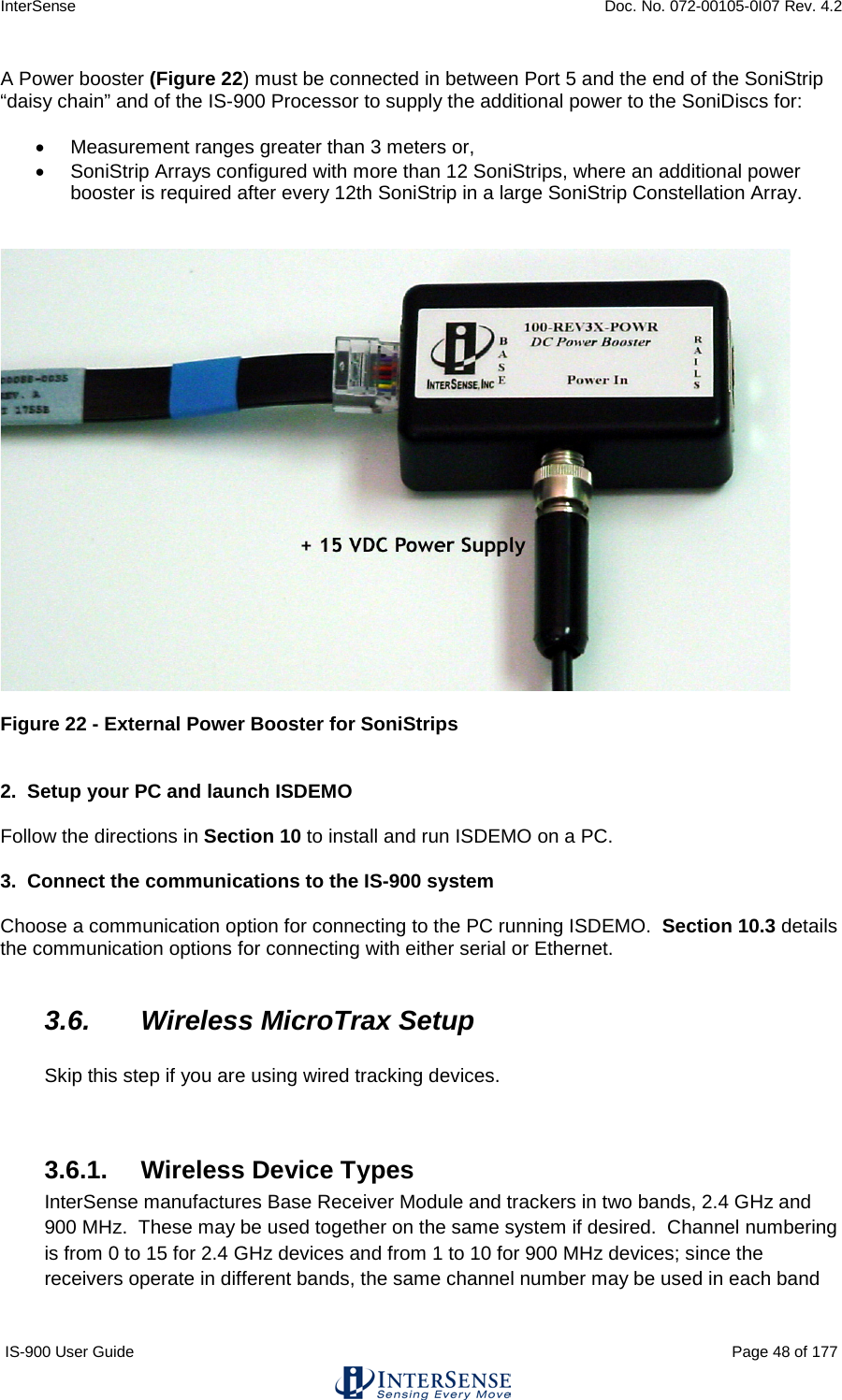
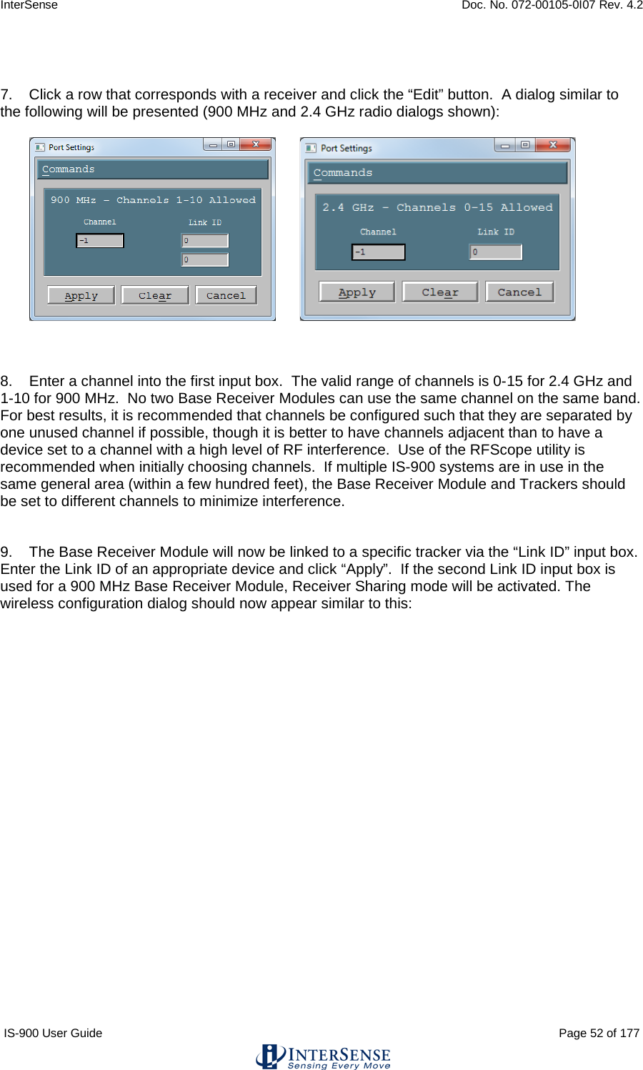
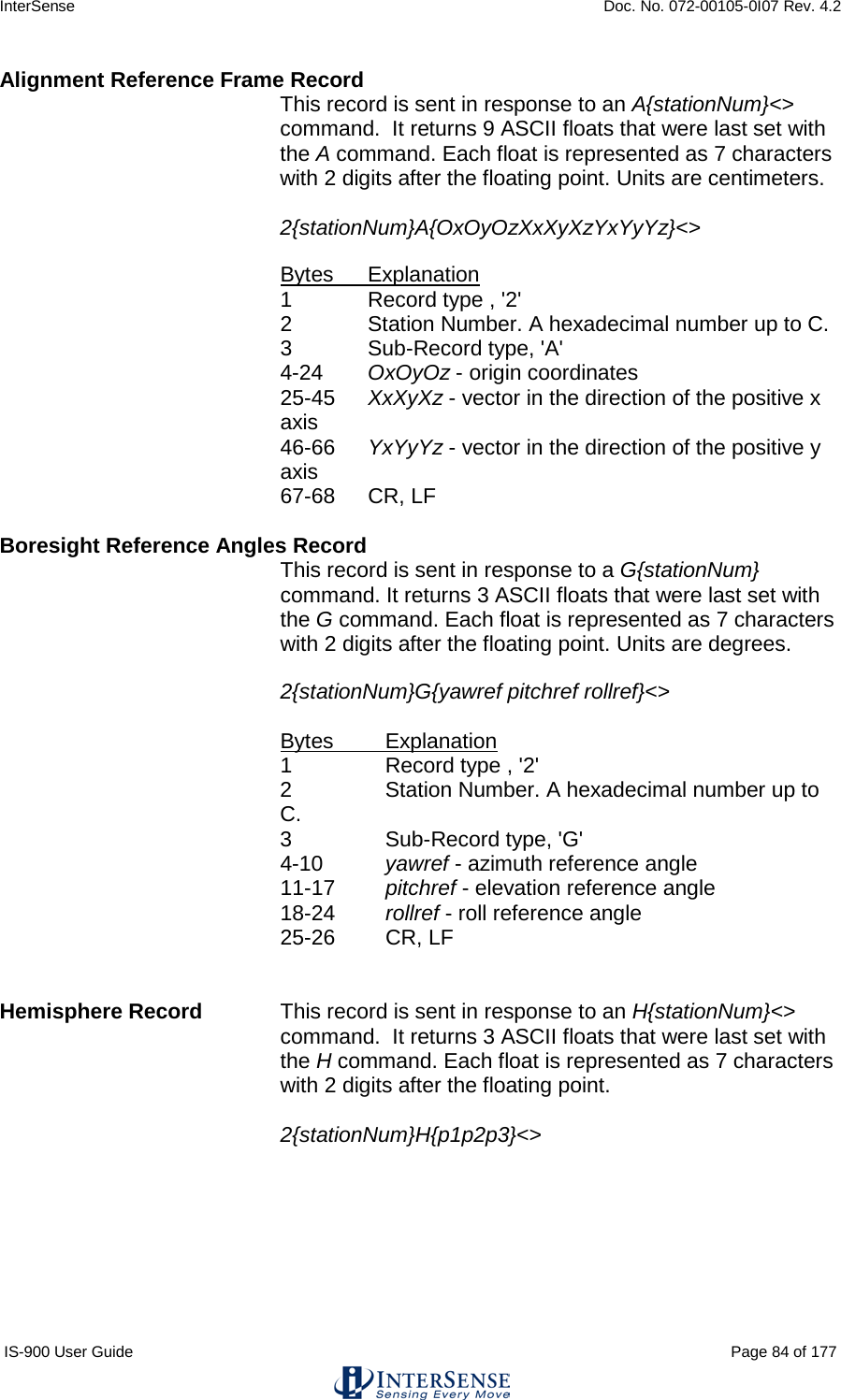
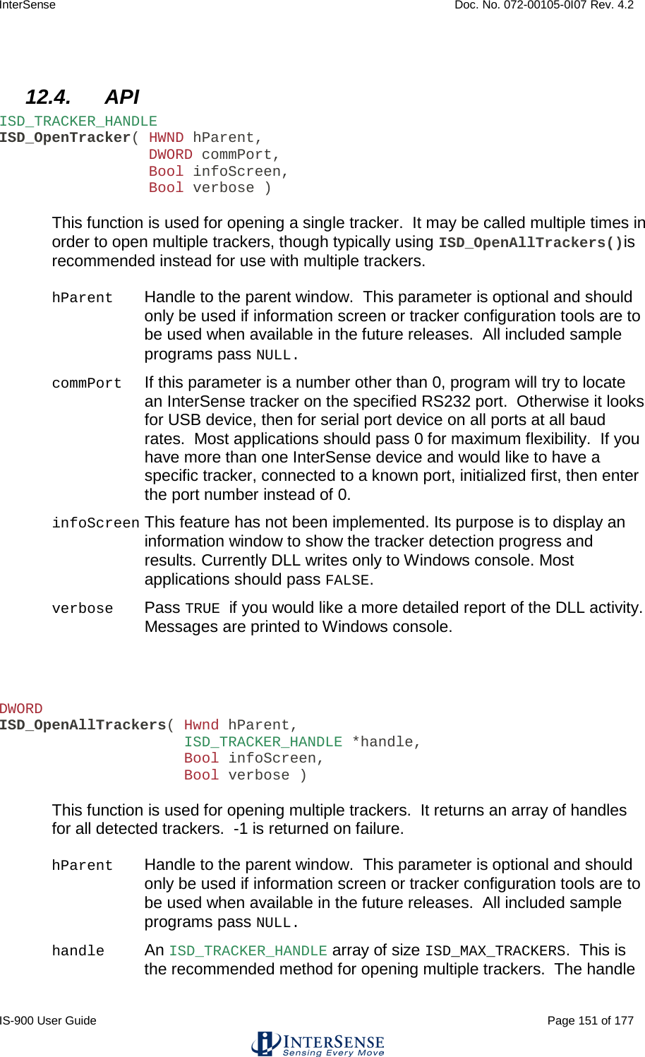
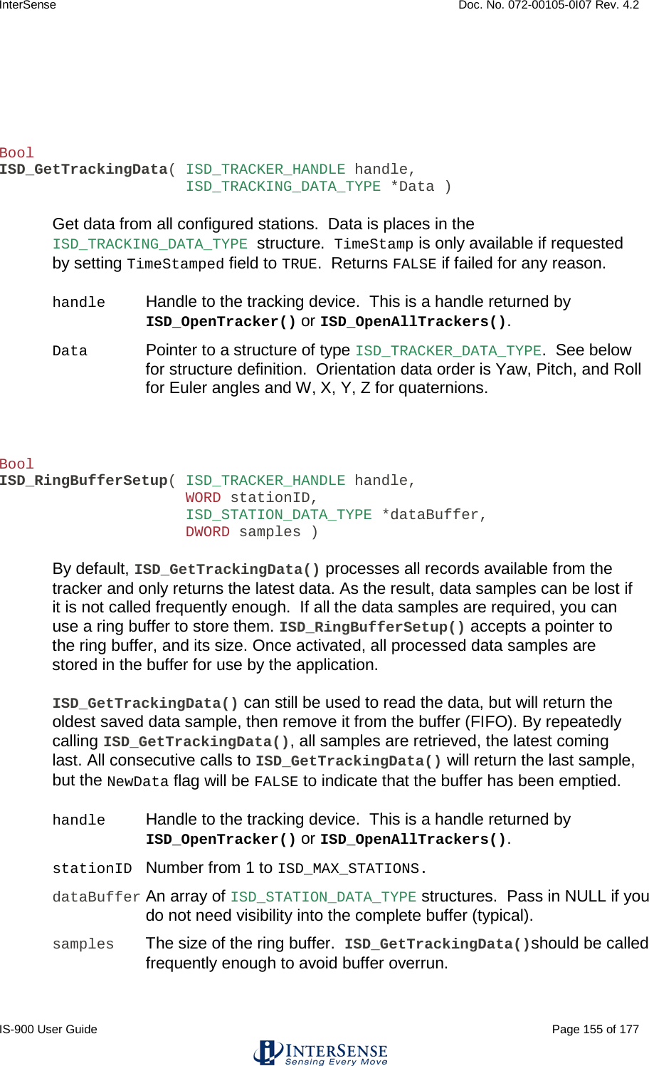
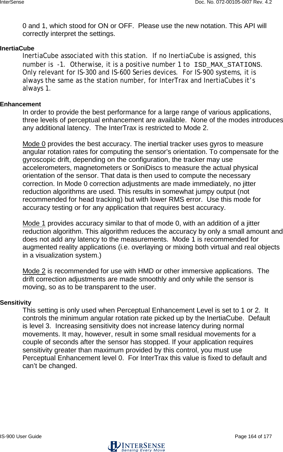
![InterSense Doc. No. 072-00105-0I07 Rev. 4.2 IS-900 User Guide Page 146 of 177 11.2. Configuring the IS-900 for GENLOCK The default operation of the tracker is free run. That is, the tracker performs updates and, in continuous mode, outputs data records as rapidly as it can. GENLOCK operation causes the tracker to synchronize updates and data record output to an external sync signal or to an internal clock. When external GENLOCK is enabled and a valid sync signal is provided, it may take several seconds to stabilize tracking. If a valid signal not present, the tracker will wait an extra period for the signal, dropping the update rate to half the sync rate. Details are discussed below. Connecting Sync Signal The external sync signal for GENLOCK on an IS-900 is on the back panel of the processor shown in Figure 44. Figure 44 - Back Panel of IS-900, SYNC IN is External GENLOCK Input Connect the sync signal to the BNC connector labeled SYNC IN on the back of the IS-900 Processor. The input interface setting for SYNC IN is controlled by software and access is provided via command or the LCD menu. This setting is saved with the rest of the user settings. Command: MGS[source]<> source 1 TTL 2 NTSC Default is TTL. If source is omitted, the current setting is returned (31GS{source}<>). From the LCD menu, GENLOCK source is selected by choosing: System Config → GENLOCK → Source (TTL and NTSC options only).](https://usermanual.wiki/Thales-Visionix/9SMLW/User-Guide-2168100-Page-146.png)
![InterSense Doc. No. 072-00105-0I07 Rev. 4.2 IS-900 User Guide Page 147 of 177 Enabling GENLOCK via Command Send the C command to the tracker to place it in continuous mode. If the tracker is used in polled mode, its internal updates will be synchronized to the sync signal but data record output will not. Send the InterSense-specific GENLOCK command to the tracker. MG[state,[rate]]<> State 0 Genlock off (free run) 1 Reserved—has no effect on the GENLOCK state. 2 Use external sync, strobe rate specified by rate parameter (manual). 3 Use internal sync, output data records at frequency specified by rate parameter. rate For state 2, the sync strobe rate in hertz. For state 3, the data record output rate in hertz. 30 Hz minimum in either case. Current settings of state and rate are reported if the command is issued without parameters (or invalid ones). The Fastrak command y{state}<> is not recognized by the IS-900, but has the equivalent function the MG command with state equal to 0 or 1. If the Fastrak y{state}<> command is used in your code, remember to manually configure GENLOCK via the LCD menu to the settings required by the application. ISDEMO can be used to send the GENLOCK command using the Send Command String option. GENLOCK settings can be saved to the tracker using ISDEMO, using the ^K command or using the LCD (if equipped). Enabling GENLOCK via LCD Menu Select Communication→Data Output→Sample Mode→Continuous to place the tracker in continuous mode. If the tracker is used in polled mode, its internal updates will be synchronized to the sync signal but data record output will not. Select System Config→GENLOCK→State and then one of the following choices. Off GENLOCK off Manual Use external sync (select strobe rate in 5 Hz increments using arrow buttons, then press the enter button) Internal Use internal sync (select data record output rate in 5 Hz increments using arrows buttons, then press the enter button)](https://usermanual.wiki/Thales-Visionix/9SMLW/User-Guide-2168100-Page-147.png)
![InterSense Doc. No. 072-00105-0I07 Rev. 4.2 IS-900 User Guide Page 148 of 177 Verifying Synchronization To verify GENLOCK is working with the IS-900, check the GENLOCK indicator in the lower-right corner of the LCD on the front panel of the processor. When GENLOCK is on and stable, the indicator displays “G”, otherwise the indicator displays an “X” indicating GENLOCK is enabled but the processor is not synchronized. If “G” or “X” is not displayed, then GENLOCK is off. Using CrystalEyes™ To configure an IS-900 for use with CrystalEyes™, set the sync signal type to TTL and send the command MG2,120 or MG2,60 to the tracker (assuming the video refresh rate is 60 Hz or 120 Hz per eye). Connect the external sync signal used for the CrystalEyes™ IR emitter to the SYNC IN on the back panel of the IS-900 Processor. Adjusting Phase Point A data record is output once per sync period when the tracker is in continuous mode. The phase point is the time within the sync period at which a data record is transmitted and is adjustable for internal and external GENLOCK. The phase point is specified as a percentage of the sync period. 0% (the default) instructs the tracker to output a data record as soon as possible after the sync period begins. 100% delays the output of a record as much as possible before the next sync period begins. To adjust phase point via command: MGP[+/-]<> Increase/decrease to next/preceding phase point MGP[p]<> Set phase point to percentage specified by p (0 to 100) The current phase point is reported if the command is issued without parameters (or invalid ones). The tracker will accept the first form of the command only after GENLOCK is established. With the second form of the command, the tracker will match the specified phase point as best it can, but typically with far less resolution than 1/100th of the sync period. To set the phase point via the LCD menu, select System Config→Genlock→Phase→Set and change the value with the arrow buttons, then press the enter button. To increase or decrease to the next or previous phase point, select System Config→Genlock→Phase→Increase or →Decrease. Adjust the phase to the latest point in the cycle (for minimum latency) such that the system still behaves smoothly during head rotation (no render cycles last beyond the deadline for the next scan out).](https://usermanual.wiki/Thales-Visionix/9SMLW/User-Guide-2168100-Page-148.png)
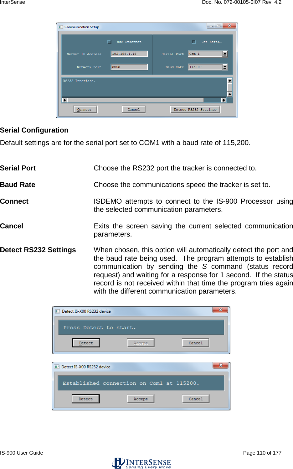
![InterSense Doc. No. 072-00105-0I07 Rev. 4.2 IS-900 User Guide Page 150 of 177 12.3. Usage The API provides an extensive set of functions that can read and set tracker configuration, but in its simplest form can be limited to just 3 or 4 function calls, as shown in the simple example below: #include <stdio.h> #include "isense.h" #ifdef UNIX #include <unistd.h> #endif void main() { ISD_TRACKER_HANDLE handle; ISD_TRACKER_INFO_TYPE tracker; ISD_TRACKING_DATA_TYPE data; int i; handle = ISD_OpenTracker((Hwnd)NULL, 0, FALSE, FALSE ); if ( handle > 0 ) printf( "\n Az El Rl X Y Z \n" ); else printf( "Tracker not found. Press any key to exit" ); for (i=0; i < 20; i++) { if ( handle > 0 ) { ISD_GetTrackingData( handle, &data ); printf( "%7.2f %7.2f %7.2f %7.3f %7.3f %7.3f ", data.Station[0].Euler[0], data.Station[0].Euler[1], data.Station[0].Euler[2], data.Station[0].Position[0], data.Station[0].Position[1], data.Station[0].Position[2] ); ISD_GetCommInfo( handle, &tracker ); printf( "%5.2f Kb/s %d Rec/s \r", tracker.KBitsPerSec, tracker.RecordsPerSec ); fflush(0); } #ifdef _WIN32 Sleep( 1000 ); #elif defined UNIX usleep(1e6); #endif } ISD_CloseTracker( handle ); }](https://usermanual.wiki/Thales-Visionix/9SMLW/User-Guide-2168100-Page-150.png)
![InterSense Doc. No. 072-00105-0I07 Rev. 4.2 IS-900 User Guide Page 163 of 177 12.5.2. ISD_STATION_INFO_TYPE This data structure is used to get and set station configuration, using ISD_GetStationConfig() and ISD_SetStationConfig(). typedef struct { DWORD ID; Bool State; Bool Compass; LONG InertiaCube; DWORD Enhancement; DWORD Sensitivity; DWORD Prediction; DWORD AngleFormat; Bool TimeStamped; Bool GetInputs; Bool GetEncoderData; BYTE CompassCompensation; BYTE ImuShockSuppression; BYTE UrmRejectionFactor; BYTE bReserved2; DWORD CoordFrame DWORD AccelSensitivity; float fReserved1; float fReserved2; float TipOffset[3]; float fReserved3; Bool GetCameraData; Bool GetAuxInputs; Bool GetCovarianceData; Bool GetExtendedData; } ISD_STATION_INFO_TYPE; ID A unique number identifying a station. It is the same as that passed to the ISD_SetStationConfig() and ISD_GetStationConfig() functions and can be 1 to ISD_MAX_STATIONS. State TRUE if on, FALSE if off. InertiaCubes are considered to be a tracking system consisting of one station, which cannot be turned off, so this field will always be TRUE. The IS-900 may have up to 7 stations connected. Compass Only available for InertiaCube devices. For all others this setting is always 2. This controls the state of the compass component of the InertiaCube. Compass is only used when station is configured for GEOS or Dual modes, in Fusion mode compass readings are not used, regardless of this setting. When station is configured for full compass mode, the readings produced by the magnetometers inside the InertiaCube are used as absolute reference orientation for yaw. Compass can be affected by metallic objects and electronic equipment in close proximity to an InertiaCube. Older versions of tracker firmware supported only](https://usermanual.wiki/Thales-Visionix/9SMLW/User-Guide-2168100-Page-163.png)
![InterSense Doc. No. 072-00105-0I07 Rev. 4.2 IS-900 User Guide Page 167 of 177 12.5.3. ISD_TRACKING_DATA_TYPE This data structure is used to return current data for a station, including position, orientation, time stamp, button and analog channel state. It is passed to ISD_GetTrackingData() as part of ISD_TRACKING_DATA_TYPE typedef struct { ISD_STATION_DATA_TYPE Station[ISD_MAX_STATIONS]; } ISD_TRACKING_DATA_TYPE; typedef struct { BYTE TrackingStatus; BYTE NewData; BYTE CommIntegrity; BYTE BatteryState float Euler[3]; float Quaternion[4]; float Position[3]; float TimeStamp; float StillTime; float BatteryLevel; float CompassYaw; Bool ButtonState[ISD_MAX_BUTTONS]; short AnalogData[ISD_MAX_CHANNELS]; BYTE AuxInputs[ISD_MAX_AUX_INPUTS]; float AngularVelBodyFrame[3]; float AngularVelNavFrame[3]; float AccelBodyFrame[3]; float AccelNavFrame[3]; float VelocityNavFrame[3]; float AngularVelRaw[3]; BYTE MeasQuality; BYTE bReserved2; BYTE bReserved3; BYTE bReserved4; DWORD TimeStampSeconds; DWORD TimeStampMicroSec; DWORD OSTimeStampSeconds; DWORD OSTimeStampMicroSec; float Reserved[56]; float MagBodyFrame[3]; } ISD_STATION_DATA_TYPE;](https://usermanual.wiki/Thales-Visionix/9SMLW/User-Guide-2168100-Page-167.png)
![InterSense Doc. No. 072-00105-0I07 Rev. 4.2 IS-900 User Guide Page 171 of 177 12.5.4. ISD_HARDWARE_INFO_TYPE This data structure is used to return system hardware information using ISD_GetSystemHardwareInfo(). For more detailed descriptions of elements in the structure, please reference the comments in the isense.h file. typedef struct { Bool Valid; DWORD TrackerType; DWORD TrackerModel; DWORD Port; DWORD Interface; Bool OnHost; DWORD AuxSystem; float FirmwareRev; char ModelName[128]; struct { Bool Position; Bool Orientation; Bool Encoders; Bool Prediction; Bool Enhancement; Bool Compass; Bool SelfTest; Bool ErrorLog; Bool UltVolume; Bool UltGain; Bool UltTimeout; Bool PhotoDiode; DWORD MaxStations; DWORD MaxImus; DWORD MaxFPses; DWORD MaxChannels; DWORD MaxButtons; Bool MeasData; Bool DiagData; Bool PseConfig; Bool ConfigLock; float UltMaxRange; float fReserved2; float fReserved3; float fReserved4; Bool CompassCal; Bool bReserved2; Bool bReserved3; Bool bReserved4; DWORD dwReserved1;](https://usermanual.wiki/Thales-Visionix/9SMLW/User-Guide-2168100-Page-171.png)
![InterSense Doc. No. 072-00105-0I07 Rev. 4.2 IS-900 User Guide Page 172 of 177 DWORD dwReserved2; DWORD dwReserved3; DWORD dwReserved4; } Capability; Bool bReserved1; Bool bReserved2; Bool bReserved3; Bool bReserved4; DWORD BaudRate; DWORD NumTestLevels; DWORD dwReserved3; DWORD dwReserved4; float fReserved1; float fReserved2; float fReserved3; float fReserved4; char cReserved1[128]; char cReserved2[128]; char cReserved3[128]; char cReserved4[128]; } ISD_HARDWARE_INFO_TYPE;](https://usermanual.wiki/Thales-Visionix/9SMLW/User-Guide-2168100-Page-172.png)
![InterSense Doc. No. 072-00105-0I07 Rev. 4.2 IS-900 User Guide Page 173 of 177 12.5.5. ISD_STATION_HARDWARE_INFO_TYPE This data structure is used to return station (individual tracking device) hardware information using ISD_GetStationHardwareInfo(). For more detailed descriptions of elements in the structure, please reference the comments in the isense.h file. typedef struct { Bool Valid; DWORD ID; char DescVersion[20]; float FirmwareRev; DWORD SerialNum; char CalDate[20]; DWORD Port; struct { Bool Position; Bool Orientation; DWORD Encoders; DWORD NumChannels; DWORD NumButtons; DWORD AuxInputs; DWORD AuxOutputs; Bool Compass; Bool bReserved1; Bool bReserved2; Bool bReserved3; Bool bReserved4; DWORD dwReserved1; DWORD dwReserved2; DWORD dwReserved3; DWORD dwReserved4; } Capability; Bool bReserved1; Bool bReserved2; Bool bReserved3; Bool bReserved4; DWORD Type; DWORD DeviceID; DWORD dwReserved3; DWORD dwReserved4; float fReserved1; float fReserved2; float fReserved3; float fReserved4; char cReserved1[128]; char cReserved2[128]; char cReserved3[128]; char cReserved4[128]; } ISD_STATION_HARDWARE_INFO_TYPE;](https://usermanual.wiki/Thales-Visionix/9SMLW/User-Guide-2168100-Page-173.png)
![InterSense Doc. No. 072-00105-0I07 Rev. 4.2 IS-900 User Guide Page 174 of 177 12.5.6. ISD_PORT_WIRELESS_INFO_TYPE This data structure is used to information about the wireless hardware on a given port, using ISD_GetPortWirelessInfo(). The radioVersion field can be used to check the type of radio hardware: 2.4 GHz (Aerocomm, radio used with older MiniTrax trackers): 15 or 31 2.4 GHz (Chipcon, MicroTrax only): 128 900 MHz (MicroTrax only): 144 868 MHz (MicroTrax only): 160 typedef struct { Bool valid; LONG status; Bool wireless; DWORD channel; DWORD id[4]; DWORD radioVersion; DWORD dReserved1; DWORD dReserved2; DWORD dReserved3; DWORD dReserved4; } ISD_PORT_WIRELESS_INFO_TYPE;](https://usermanual.wiki/Thales-Visionix/9SMLW/User-Guide-2168100-Page-174.png)
![InterSense Doc. No. 072-00105-0I07 Rev. 4.2 IS-900 User Guide Page 175 of 177 13. Appendix H – Interface Protocol Commands – Quick Reference For further detail, see: Section 4.2 Standard Fastrak™ Interface Commands, pages 63-71. Section 4.3 Fastrak™ Commands Implemented for Compatibility, page 71. Section 4.4 InterSense specific Commands, pages 71-80. NOTE: “<>” represents a newline character, and “^” represents a control character Command Syntax Data Record Request P Output mode C Set continuous output mode c Set polled output mode Alignment Reference Frame A{stationNum},[Ox,Oy,Oz,Xx,Xy,Xz,Yx,Yy,Yz]<> Reset Alignment Reference Frame R{stationNum}<> Boresight Reference Angles G{stationNum},[yawref, pitchref, rollref]<> Boresight Compatibility Mode MBF<> Switch to Fastrak Compatible mode. MBI<> Switch to Version 2.x Compatible mode (default). Boresight B{stationNum}<> (Fastrak compatibility mode) MB{stationNum}<> (Version 2.x compatibility mode) Unboresight b{stationNum}<> (Fastrak compatibility mode) Mb{stationNum}<> (Version 2.x compatibility mode) Heading Boresight B{stationNum}<> (Version 2.x compatibility mode) MB{stationNum}<> (Fastrak compatibility mode) Heading Unboresight b{stationNum}<> (Version 2.x compatibility mode) Mb{stationNum}<> (Fastrak compatibility mode) . Set Serial Communication Parameters o{rate,parity,bits,HHS}<> System Record Request S Station Status l{stationNum},[state]<> Output Units Control U Set units to inches. u Set units to centimeters. System control ^K Save current settings to non-volatile memory. W Restore factory default settings. ^Y Restart the firmware to the power up condition. ^S Suspend data transmission. ^Q Resume data transmission. Output record mode F Put in ASCII output mode. f Put in Binary output mode.](https://usermanual.wiki/Thales-Visionix/9SMLW/User-Guide-2168100-Page-175.png)
![InterSense Doc. No. 072-00105-0I07 Rev. 4.2 IS-900 User Guide Page 176 of 177 Output record list settings O{stationNum},[p1],[p2],[p3],.....,[pn]<> Define Tip Offsets N{stationNum},[Ox, Oy, Oz]<> Position Operational Envelope V{stationNum},[Xmax,Ymax,Zmax,Xmin,Ymin,Zmin]<> Hemisphere H{stationNum},[p1,p2,p3]<> Time Units MT<> Sets to milliseconds. Mt<> Sets to microseconds. Set Current Time to Zero MZ<> Ethernet Communication Parameters MEthIp{address}<> Set IP address MEthTcpPort{port}<> Set TCP port MEthUdp{state}<> Set UDP state MEthUdpPort{port}<> Set UDP port MEthSubnet{subnet}<> Set subnet MEthMode{mode}<> Set manual or DHCP mode MEthApply<> Apply Ethernet settings InterSense System Status Record Request MS<> Tracking Status Record Request MP<> Genlock Synchronization MG[State, Rate]<> Genlock Phase MGP[Param]<> Configuration Lock MConfigLockMode{Mode}<> SoniStrip LED Control ML[state] Error reporting ME<> MEC<> ME1<> ME0<> Command Logging MLogOpen<> MLogClose<> MLogClear<> MLogState<> MLogSend<> InterSense Station Status Record Request Ms{stationNum}<> Prediction Interval Mp{stationNum},[Interval]<> Perceptual Enhancement Level MF{stationNum},{Mode}<> Compass Heading Correction MH{stationNum},{state}<> Rotational Sensitivity Level MQ{stationNum},[Sensitivity Level]<> Associate Fixed PSE with a Constellation MCF{FPSE number}, {xp, yp, zp, xn, yn, zn, IDcode}<> Disassociate Fixed PSE from Constellation MCf[Fixed PSE number, IDcode]<> Clear All Fixed PSEs (Constellation) MCC<> Apply New Configuration MCe<> Cancel Configuration Session MCx<>](https://usermanual.wiki/Thales-Visionix/9SMLW/User-Guide-2168100-Page-176.png)
![InterSense Doc. No. 072-00105-0I07 Rev. 4.2 IS-900 User Guide Page 177 of 177 [END]](https://usermanual.wiki/Thales-Visionix/9SMLW/User-Guide-2168100-Page-177.png)