Thales Visionix 9SMLW Ultrasonic Tracking Device User Manual Version 2 2
Thales Visionix, Inc. Ultrasonic Tracking Device Version 2 2
User Manual.pdf

InterSense Doc. No. 072-00105-0I07 Rev. 4.2
IS-900 User Guide Page 2 of 177
User Guide for the IS-900 SimTracker, SimTracker LT, & VETracker
Firmware 4.29 and higher
DLL Version 4.237 and higher
Contacting InterSense
Please contact us if you need assistance.
Thales Visionix, Inc.
700 Technology Park Drive, Suite 102
Billerica, Massachusetts 01821
USA
Telephone: +1 781 541 6330 Internet: http://www.intersense.com
Fax: +1 781 541 6329 email: ISinfo@intersense.com
Technical Support: +1 781 541 7624 email: techsupport@intersense.com
Sales: +1 781 541 7650 email: sales@intersense.com
Patents
The label below identifies the protection granted by the Government of the United States
to InterSense for its products:
Trademarks
InterSense™, InertiaCube™, InertiaCube2™, SoniDisc™, SoniStrip™, SoniFrame™,
SoniPod™, IS-900™, VETracker™, SimTracker™, ISDEMO™, GEOS™, PULSAR™,
CONSTELLATION™, MicroTrax™ are trademarks of Thales Visionix, Inc. All other
trademarks are the property of their respective owners.
Copyright
2013
Thales Visionix, Inc.
U.S. Patents
5645077, 5807284, 6162191, 6176837, 6314055, 6361507,
6409687, 6474159, 6681629, 6757068, 6786877, 6922632,
700469 and Patents Pending

InterSense Doc. No. 072-00105-0I07 Rev. 4.2
IS-900 User Guide Page 3 of 177
Regulatory Statements and Approvals
FCC Compliance Statement for SimTracker and VETracker Systems
This device complies with part 15 of the FCC Rules. Operation is subject to the following two
conditions: (1) This device may not cause harmful interference, and (2) this device must accept
any interference received, including interference that may cause undesired operation.
Note: this equipment has been tested and found to comply with the limits for a Class A digital
device, pursuant to part 15 of the FCC Rules. These limits are designed to provide reasonable
protection against harmful interference when the equipment is operated in a commercial
environment. This equipment generates, uses, and can radiate radio frequency energy and, if not
installed and used in accordance with the instruction manual, may cause harmful interference to
radio communications. Operation of this equipment in a residential area is likely to cause harmful
interference in which case the user will be required to correct the interference at his own
expense.
Important: Changes or modifications to this product not authorized by InterSense, Inc. could void
the EMC compliance and negate your authority to operate the product. This product was tested
for EMC compliance under conditions that included the use of InterSense peripheral devices and
InterSense cables and connectors between system components. It is important that you use
InterSense peripheral devices, cables, and connectors between system components to reduce
the possibility of causing interference to radios, TV sets, and other electronic devices. You can
obtain InterSense peripheral devices, cables, and connectors from InterSense or through an
InterSense Authorized Reseller.
Responsible party (contact for FCC matters):
Thales Visionix, Inc.
700 Technology Park Drive, Suite 102
Billerica, MA 01821
Industry Canada Statement
This Class A digital apparatus complies with Canadian ICES-003.
Cet appareil numérique de la classe A est conforme à la norme NMB-003 du Canada.
European Community
Products with the below CE marking comply with the directives issued by the Commission of the
European Community.
Warning
This is a Class A product. In a domestic environment this product may cause radio
interference in which case the user may be required to take adequate measures.

InterSense Doc. No. 072-00105-0I07 Rev. 4.2
IS-900 User Guide Page 4 of 177
FCC Compliance Statement for SimTracker LT Systems
This equipment has been tested and found to comply with the limits for a Class B digital device,
pursuant to Part 15 of the FCC Rules. These limits are designed to provide reasonable protection
against harmful interference in a residential installation. This equipment generates uses and can
radiate radio frequency energy and, if not installed and used in accordance with the instructions,
may cause harmful interference to radio communications. However, there is no guarantee that
interference will not occur in a particular installation. If this equipment does cause harmful
interference to radio or television reception, which can be determined by turning the equipment
off and on, the user is encouraged to try to correct the interference by one of the following
measures:
- Reorient or relocate the receiving antenna.
- Increase the separation between the equipment and receiver.
- Connect the equipment into an outlet on a circuit different from that to which the receiver is
connected.
- Consult the dealer or an experienced radio/TV technician for help.
This device complies with Part 15 of the FCC Rules. Operation is subject to the following two
conditions: (1) This device may not cause harmful interference, and (2) this device must accept
any interference received, including interference that may cause undesired operation.
FCC Caution: Any changes or modifications not expressly approved by the party responsible for
compliance could void the user's authority to operate this equipment.
To comply with FCC’s and Industry Canada’s RF radiation exposure limits for general
population/uncontrolled exposure, the antenna(s) used for this transmitter must be installed to
provide a separation distance of at least 20 cm from all persons and must not be collocated or
operating in conjunction with any other antenna or transmitter.
This device complies with Industry Canada licence-exempt RSS standard(s). Operation is
subject to the following two conditions: (1) this device may not cause interference, and (2)
this device must accept any interference, including interference that may cause undesired
operation of the device.
Le présent appareil est conforme aux CNR d'Industrie Canada applicables aux appareils radio
exempts de licence. L'exploitation est autorisée aux deux conditions suivantes : (1) l'appareil
ne doit pas produire de brouillage, et (2) l'utilisateur de l'appareil doit accepter tout brouillage
radioélectrique subi, même si le brouillage est susceptible d'en compromettre le
fonctionnement.
Under Industry Canada regulations, this radio transmitter may only operate using an antenna
of a type and maximum (or lesser) gain approved for the transmitter by Industry Canada. To
reduce potential radio interference to other users, the antenna type and its gain should be so
chosen that the equivalent isotropically radiated power (e.i.r.p.) is not more than that
necessary for successful communication.
Conformément à la réglementation d'Industrie Canada, le présent émetteur radio peut
fonctionner avec une antenne d'un type et d'un gain maximal (ou inférieur) approuvé pour
l'émetteur par Industrie Canada. Dans le but de réduire les risques de brouillage
radioélectrique à l'intention des autres utilisateurs, il faut choisir le type d'antenne et son gain
de sorte que la puissance isotrope rayonnée équivalente (p.i.r.e.) ne dépasse pas l'intensité
nécessaire à l'établissement d'une communication satisfaisante.

InterSense Doc. No. 072-00105-0I07 Rev. 4.2
IS-900 User Guide Page 5 of 177
Warnings and Precautionary Statements
Any changes or modifications to the IS-900 SimTracker/VETracker,
MicroTrax Tracking Devices and other components of the IS-900 System
not expressly approved by InterSense will void the warranty and any
regulatory compliance issued for the system. This could also void the
user’s authority to operate the equipment.
MicroTrax device microphones are susceptible to ESD and may require
power cycling to recover from communication failure.
Do not drop or otherwise shock the tracking devices for they can be
permanently damaged.
Do not bend, twist, pull strongly or tamper in any way with any part of the
cabling.
Take care to avoid electric shocks. Do not plug-in or unplug the power
cable with wet hands.
Please see Appendix C for Health and Safety warnings and guidelines
Wireless Devices
This device contains a Lithium Ion battery that should only be used with the following warnings
and precautions.
• Avoid short circuits
• Do not dispose of the battery in fire
• Do not heat the batteries above 60°C
• Do not solder directly to the batteries
• Do not charge above 4.2V
• Do not charge below 0°C or above 45°C
• Do not discharge below 2.7V
• Do not discharge below 20°C or above 60°C
• Do not insert the batteries in reverse polarity
Warning: Fire, Explosion, and Severe Burn Hazard
InterSense Doc. No. 072-00105-0I07 Rev. 4.2
IS-900 User Guide Page 6 of 177
Equipment Design:
• To avoid damage to the battery pack, make sure that the battery pack is positioned away
from heat sources in the equipment.
• If the battery pack is designed into other equipment, use caution to strictly avoid designing
airtight battery compartments.
When using the battery
Misusing the battery may cause the battery to get hot, explode, or ignite and
cause serious injury. Be sure to follow the safety rules listed below:
Do not place the battery in fire or heat the battery.
Do not pierce the battery with nails, strike the battery with a hammer, step
on the battery, or otherwise subject it to strong impacts or shocks.
Do not expose the battery to water or salt water or allow the battery to get
wet.
Do not disassemble or modify the battery. The battery contains safety and
protection devices, which, if damaged, may cause the battery to generate heat,
explode or ignite.
Do not place the battery on or near fires, stoves, or other high-temperature
locations. Do not place the battery in direct sunshine, or store the battery
inside cars in hot weather. Doing so may cause the battery to generate heat,
explode, or ignite. Using the battery in this manner may also result in the loss
of performance and shortened life expectancy.
When the battery will no longer hold a charge, contact InterSense for servicing
options. Do not exchange with any other battery.
Immediately discontinue use of the battery if, while using, charging or storing
the battery the battery emits an unusual smell, feels hot, changes color,
changes shape or appears abnormal in any other way. Contact InterSense if
any of these problems have been observed.
Do not place the batteries in microwave ovens, high-pressure containers, or on
induction cookware.
In the event that the battery leaks and fluid gets into one’s eye, do not rub the
eye. Rinse well with water and immediately seek medical care. If left untreated
the battery fluid could cause damage to the eye.
InterSense Doc. No. 072-00105-0I07 Rev. 4.2
IS-900 User Guide Page 7 of 177
While charging the battery
Follow the rules listed below while charging the battery. Failure to do so may
cause the battery to become hot, explode, or ignite and cause serious injury.
• When charging the battery use only InterSense’s charging station (100-
91000-EWBS) or individual device charger (099-00076-0000)
Note: * means that the suffix is U, E or K depending on voltage requirements
of your country.
• Do not place the batteries in or near fire, or into direct sunlight. When the
battery becomes hot, the built in safety equipment is activated, preventing
the battery from charging further. Over-heating the battery can destroy the
safety equipment and can cause additional heating, breaking or ignition of
the battery.
Do not continue charging the battery if it does not recharge within the specified
charging time. Doing so may cause the battery to become hot, explode or
ignite.
The temperature range over which the battery can be charged is 0 degrees
Celsius to 45 degrees Celsius. Charging the battery at temperatures outside
of this range may cause the battery to become hot or to break. Charging the
battery outside this temperature range may also harm the performance of the
battery or reduce the battery’s life expectancy.
When discharging the battery
Do not discharge the battery using any devices except for the specified device.
When the battery is used in devices aside from the specified device, it may
damage the performance of the battery or reduce its life expectancy, and if the
device causes an abnormal current to flow, it may cause the battery to become
hot, explode or ignite and cause serious injury.
The temperature range over which the battery can be discharged is –20
degrees Celsius to 60 degrees Celsius. Use of the battery outside of this
temperature range may damage the performance of the battery or may reduce
its life expectancy.
General Warnings & Precautionary Statements
Do not drop or otherwise shock the tracking devices for they can be
permanently damaged.
Do not plug in any devices while the electrical power is applied.
Any changes or modifications to the IS-900 not expressly approved by Thales
Visionix, Inc. will void the warranty and any regulatory compliance issued for
the system.

InterSense Doc. No. 072-00105-0I07 Rev. 4.2
IS-900 User Guide Page 8 of 177
Do not bend, twist, pull strongly or tamper in any way with any part of the
IS-900 cabling.
Take care to avoid electric shocks. Do not plug-in or unplug the power cable
with wet hands.
During normal operation, the user should not make contact with the metal
surfaces, including the microphone housings and the connector hood, of the
tracking stations. Such contact could result in invalid data or a tracker reset.
Please see the section titled Health and Safety Warnings and Guidelines
Radio System Information
These devices contain a commercially available 900 MHz or 2.4 GHz non-frequency hopping
wireless data communication link.
The wireless link is intended for use in normal commercial applications. Applications requiring
extended temperature range or unusual environmental requirements such as military, medical
life-support or life-sustaining equipment are specifically not recommended without additional
testing for such applications.
The following devices:
• IS-900 MicroTrax Wireless Transmitter
o part number 100-91000-EWTX: 2.4 GHz
o part number 100-91900-EWTX: 900 MHz
These devices, with their antenna, comply with FCC’s RF radiation exposure limits set forth for an
uncontrolled environment. To maintain compliance, they must not be co-located or operate in
conjunction with any other antenna or transmitter.
Complies with Part 15 of the FCC Rules. Operation is subject to the following two conditions:
1. These devices may not cause harmful interference
2. These devices must accept any interference received, including interference that may
cause undesired operation.

InterSense Doc. No. 072-00105-0I07 Rev. 4.2
IS-900 User Guide Page 9 of 177
The following devices:
• 2.4 GHz-
o IS-900 MicroTrax Wireless Wand (part number 100-91000-EWWD)
o IS-900 16 Channel Receiver (part number 100-IS9MW-RX16)
o SimTracker LT (part number 100-9SMLW-0020)
• 900 MHz
o IS-900 MicroTrax Wireless Wand (part number 100-91900-EWWD)
o IS-900 10 Channel Receiver (part number 100-91900-EWRX)
o SimTracker LT (part number 100-9SMLW-0090)
This device complies with FCC’s RF radiation exposure limits set forth for
an uncontrolled environment. It should be installed and operated such that;
a minimum separation distance of 20cm is maintained between the radiator
(antenna) & user’s/nearby people’s body at all times. This device must not
be co-located or operating in conjunction with any other antenna or
transmitter.
Comply with Part 15 of the FCC Rules. Operation is subject to the following two conditions:
3. These devices may not cause harmful interference
4. These devices must accept any interference received, including interference that may
cause undesired operation.

InterSense Doc. No. 072-00105-0I07 Rev. 4.2
IS-900 User Guide Page 10 of 177
Table of Contents
1. System Description ................................................................................................................ 13
1.1. IS-900 Configuration ....................................................................................................... 14
1.2. IS-900 SimTracker & VETracker Processor ................................................................... 15
1.3. SoniStrips, SoniFrame, SoniWing & SoniPod acoustic pulse transmitters ..................... 16
1.4. Acoustic Constellation Mounting Considerations ............................................................ 17
1.4.1. SoniFrame & SoniWing Fixed Constellations .......................................................... 17
1.4.2. SoniPods .................................................................................................................. 18
1.5. Tracking Station Description ........................................................................................... 18
1.5.1. MicroTrax Wand with Joystick ................................................................................. 20
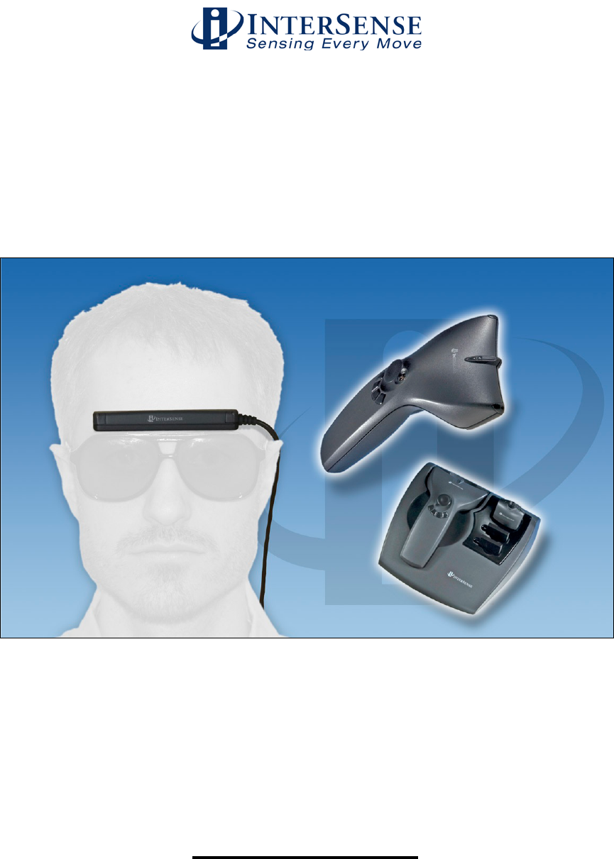
1.5.2. MicroTrax Head Tracker .......................................................................................... 21
1.5.3. MicroTrax Docking Station ....................................................................................... 22
1.5.4. MicroTrax Hand Tracker .......................................................................................... 23
1.5.5. Wireless MicroTrax Modules ................................................................................... 24
1.5.6. OEM Tracking Devices ............................................................................................ 24
1.6. IS-900 Cables, Connectors, Adaptors, Power Boosters and Wireless Radios ............... 25
1.6.1. Wired System ........................................................................................................... 25
1.6.2. Wireless System ...................................................................................................... 28
1.6.3. All Systems .............................................................................................................. 30
1.7. IS-900 Support CD .......................................................................................................... 31
2. Specifications ......................................................................................................................... 32
2.1. Performance Specifications ............................................................................................ 32
2.2. Physical Specifications .................................................................................................... 33
2.3. Environmental Specifications .......................................................................................... 34
3. Installation and Set-up ............................................................................................................ 34
3.1. InterSense Coordinate Reference Frame ....................................................................... 36
3.2. Hardware Set-up ............................................................................................................. 37
3.3. Installation of SoniStrips .................................................................................................. 38
3.3.1. SoniStrip Mounting for Ceiling Installations ............................................................. 41
3.3.2. SoniStrip Mounting for Power Wall Installations ...................................................... 42
3.3.3. SoniStrip Mounting for CAVE-like Installations ........................................................ 43
3.3.4. SoniFrame and SoniWing ........................................................................................ 44
3.4. Measurement and Calibration of SoniStrips ................................................................... 44
3.5. Connections with IS-900 Processor ................................................................................ 47
3.6. Wireless MicroTrax Setup ............................................................................................... 48
3.6.1. Wireless Device Types ............................................................................................ 48
3.6.2. Receiver Sharing (900 MHz) ................................................................................... 49
3.6.3. Wireless Device Configuration ................................................................................. 49
3.6.4. Checking the installation .......................................................................................... 54
3.6.5. Loading the Constellation File ................................................................................. 55
3.6.6. Using Wireless MicroTrax Devices .......................................................................... 61
4. Interface Communication Protocol ......................................................................................... 63
4.1. Commands Sent from the Host to the Tracker ............................................................... 63
4.2. Standard Fastrak™ Interface Commands ..................................................................... 63
4.3. Fastrak™ Commands Implemented for Compatibility .................................................... 71
4.4. InterSense specific Commands ...................................................................................... 71
4.4.1. System Configuration Commands ........................................................................... 72
4.4.2. InterSense-specific Station Parameters .................................................................. 75
4.4.3. Station and Constellation Configuration Commands ............................................... 77
4.5. Records Returned from the Tracker to the Host ............................................................. 80
4.5.1. Format Considerations............................................................................................. 80
4.5.2. Status Record Hexadecimal Character Decoding ................................................... 80
4.5.3. Fastrak™ System and Data Records ...................................................................... 81
4.5.4. InterSense-specific Records .................................................................................... 86

InterSense Doc. No. 072-00105-0I07 Rev. 4.2
IS-900 User Guide Page 11 of 177
4.5.5. Records Specific to IS-900 Models .......................................................................... 88
5. LCD Status & Settings Screen ............................................................................................... 90
5.1. Overview ......................................................................................................................... 90
5.2. Normal Operation (Steady State) .................................................................................... 91
5.3. IS-900 LCD Menu Flow Chart ......................................................................................... 95
6. Appendix A – Frequently Asked Questions ............................................................................ 96
7. Appendix B – Troubleshooting & Tips .................................................................................... 98
8. Appendix C – Health & Safety Warnings with Tracker Use Guidelines ............................... 101
9. Appendix D – Care & Maintenance ...................................................................................... 103
10. Appendix E – ISDEMO Reference ................................................................................... 104
10.1. Getting Started .......................................................................................................... 104
10.2. File Options ............................................................................................................... 108
10.3. Communications Options .......................................................................................... 109
10.4. Parameter Options .................................................................................................... 112
10.4.1. Wireless Configuration window .......................................................................... 117
10.5. Display Options ......................................................................................................... 119
10.6. Tool Options .............................................................................................................. 120
10.7. Constellation™ Configuration Tool ............................................................................ 128
10.8. RF Scope ................................................................................................................... 142
11. Appendix F – GENLOCK Synchronization ....................................................................... 144
11.1. Why Use GENLOCK? ............................................................................................... 144
11.2. Configuring the IS-900 for GENLOCK ....................................................................... 146
12. Appendix G – Developers Instructions ............................................................................. 149
12.1. Introduction ................................................................................................................ 149
12.2. Sample Program ........................................................................................................ 149
12.3. Usage ........................................................................................................................ 150
12.4. API ............................................................................................................................. 151
12.5. Data Structures .......................................................................................................... 161
12.5.1. ISD_TRACKER_INFO_TYPE ............................................................................ 161
12.5.2. ISD_STATION_INFO_TYPE .............................................................................. 163
12.5.3. ISD_TRACKING_DATA_TYPE .......................................................................... 167
12.5.4. ISD_HARDWARE_INFO_TYPE ........................................................................ 171
12.5.5. ISD_STATION_HARDWARE_INFO_TYPE....................................................... 173
12.5.6. ISD_PORT_WIRELESS_INFO_TYPE ............................................................... 174
13. Appendix H – Interface Protocol Commands – Quick Reference .................................... 175

InterSense Doc. No. 072-00105-0I07 Rev. 4.2
IS-900 User Guide Page 12 of 177
Table of Figures
Figure 1 - IS-900 Functional Diagram ........................................................................................... 14
Figure 2 - IS-900 SimTracker Processor ....................................................................................... 15
Figure 3 - IS-900 VETracker Processor ........................................................................................ 15
Figure 4 - IS-900 SoniStrips .......................................................................................................... 16
Figure 5 - IS-900 SoniWing ........................................................................................................... 16
Figure 6 - IS-900 SoniFrame with three 6 ft. SoniStrips Assembled and Mounted on a Ceiling .. 16
Figure 7 - Discrete SoniDisc Transmitter (SoniPod) ..................................................................... 17
Figure 8 - IS-900 Tracked Stations................................................................................................ 18
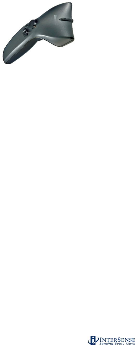
Figure 9 - MicroTrax Wand ............................................................................................................ 20
Figure 10 - MicroTrax Head Tracker ............................................................................................. 21
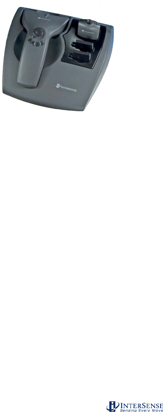
Figure 11 - MicroTrax Docking Station .......................................................................................... 22
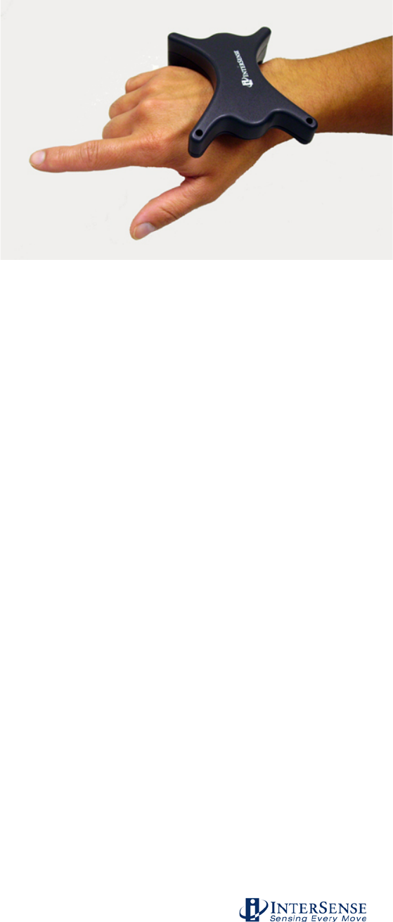
Figure 12 - MicroTrax Hand Tracker ............................................................................................. 23
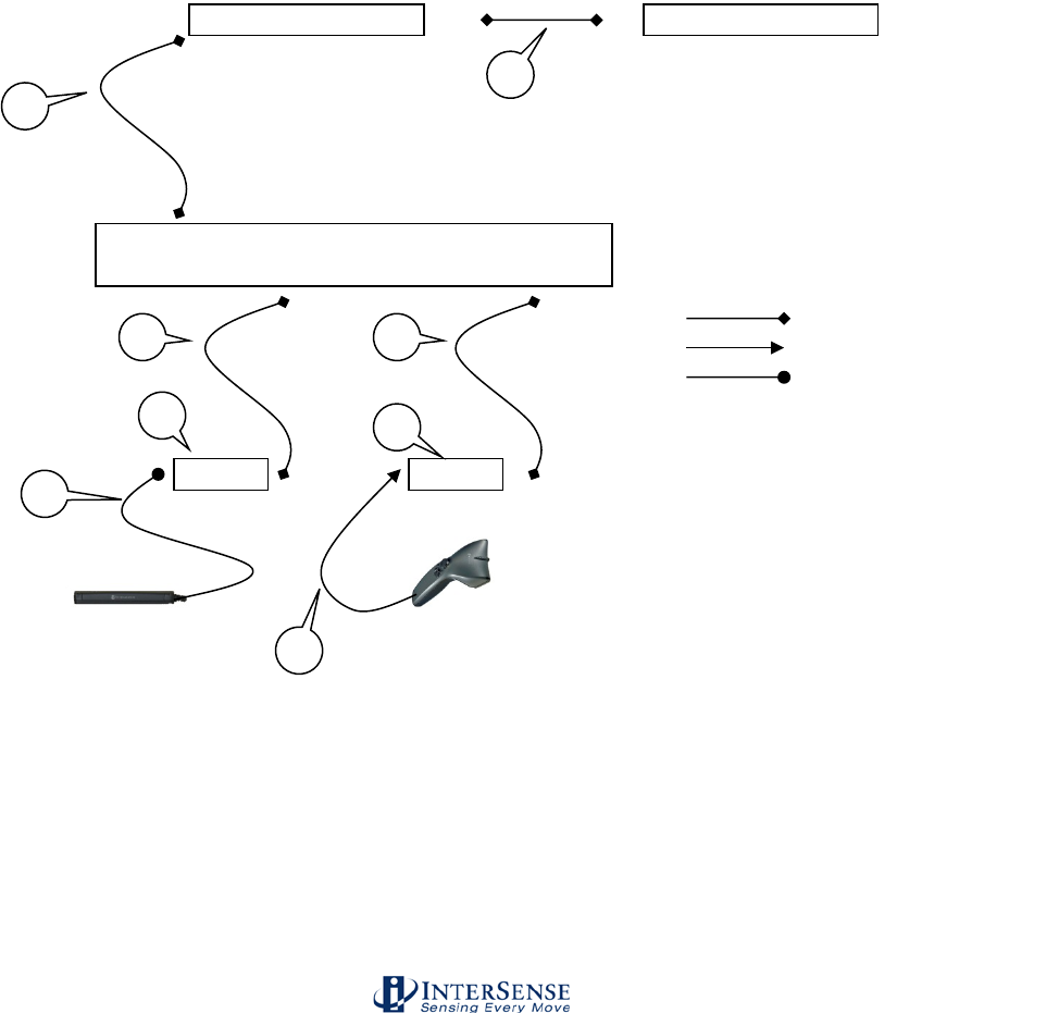
Figure 13 - Wired IS-900 and MicroTrax Cables, Connectors and Adapters ................................ 25
Figure 14 - Wireless IS-900 and MicroTrax Cables, Connectors and Adapters ........................... 28
Figure 15 - SoniStrip Power Booster (Optional) ............................................................................ 30
Figure 16 - InterSense Coordinate Reference Frame ................................................................... 36
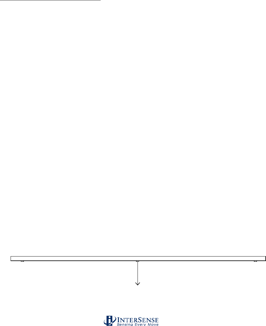
Figure 17 - Unit Normal Vector Definition for Ceiling Installed SoniStrip ...................................... 38
Figure 18 - Tracking Coverage with Two SoniStrips ..................................................................... 39
Figure 19 - Immersive Room Ceiling Mounting (top down view) ................................................... 41
Figure 20 - Power Wall Perimeter mounting (front forward view) ................................................. 42
Figure 21 - CAVE-like Installation (top down view) ....................................................................... 43
Figure 22 - External Power Booster for SoniStrips ........................................................................ 48
Figure 23 - Configuration Script Menu for loading SoniStrip Constellation array file .................... 55
Figure 24 - Configuration Script File Menu .................................................................................... 56
Figure 25 - Sending Configuration Script to Tracker ..................................................................... 56
Figure 26 - Constellation Tool Selection ....................................................................................... 57
Figure 27 - Checking installed SoniStrip Constellation Array ........................................................ 57
Figure 28 - ISDEMO Constellation Tool Screen for Ceiling Mount Power Wall Applications ....... 58
Figure 29 - ISDEMO Constellation Tool Screen for Wall Mount Power Wall Applications ........... 58
Figure 30 - ISDEMO Constellation Tool Screen for CAVE-like Applications ................................ 58
Figure 31 - ISDEMO Constellation Tool Screen with Tracking Devices ....................................... 59
Figure 32 - Tracking Status Display on IS-900 LCD Panel ........................................................... 59
Figure 33 - Saving All Configuration Settings to IS-900 Processor ............................................... 60
Figure 34 - Locking Configuration Settings in IS-900 Processor .................................................. 60
Figure 35 - IS-900 LCD Status & Settings Screen ........................................................................ 90
Figure 36 - LCD Panel in Normal Display Mode (Tracking One Station) ...................................... 91
Figure 37 - Status Display of Additional Tracking Stations ........................................................... 91
Figure 38 - Rejected Measurement Status for Tracking Station 1 ................................................ 92
Figure 39 - Communication Integrity Status for a Wired Tracking Station 1 ................................. 93
Figure 40 - Tracking Quality Status for a Wired Tracking Station 1 .............................................. 93
Figure 41 - IS-900 LCD Menu Flow Chart ..................................................................................... 95
Figure 42 - Timing Diagram: IS-900 Interfaced to PC with 60 Hz Display Refresh .................... 144
Figure 43 - Timing Diagram: IS-900 Adjusted with Proper Phase for 60 Hz Display Refresh ... 145
Figure 44 - Back Panel of IS-900, SYNC IN is External GENLOCK Input .................................. 146

InterSense Doc. No. 072-00105-0I07 Rev. 4.2
IS-900 User Guide Page 13 of 177
1. System Description
The IS-900 product family delivers precision motion tracking technology for simulators, training,
virtual, and immersive display systems. The IS-900, designed for dedicated, precision 6 degree
of freedom (6-DOF) motion tracking for both small tracking area simulators and large area virtual
environments.
This manual covers two IS-900 product configurations – the IS-900 SimTracker (Simulation
Tracker) and the IS-900 VETracker (Virtual Environment Tracker). The SimTracker is ideal for
smaller 3D environments such as cockpit or desktop simulators while the VETracker is ideal for
large immersive 3D environments. This manual also covers the wireless MicroTraxTM devices for
the IS-900 System. Please note that custom configurations are also available.
The IS-900 product design provides a great deal of flexibility for OEM configurations. While the
specific configuration of your IS-900 system may vary from the SimTracker and VETracker
standard products, the fundamental set-up, calibration, and operation principles remain the same
as described in this manual.
The system operates on hybrid technology combining inertial and ultrasonic tracking. The output
of the miniature inertial components (both accelerometers and gyros found in each tracking
device) determines position and orientation of the tracking stations. Using advanced Kalman
filters, constant drift correction is applied by fusing the output of the inertial sensors with range
measurements obtained from the ultrasonic components. The result is full 6-DOF data that is
very smooth, precise, and free from jitter.
Advantages of the IS-900 technology include:
• Low cost system utilizes IS-900 technology for small area tracking
• Immune to metallic, most acoustic, and optical interference
• Sensor design eliminates acoustic transmitter “line of sight” blockage
• Consistent accuracy over entire tracking volume
• Factory calibration configurations available for accurate position mapping of acoustic
transmitters
• Superior motion prediction algorithms
• Integration of tracking devices into OEM applications
Wireless MicroTraxTM Devices
The MicroTraxTM wireless tracker options for the IS-900 system allow for untethered 6 degree of
freedom (6-DOF) tracking. They can also be used along with wired tracking devices.
The radio/battery modules have lithium polymer batteries with enough capacity to provide 6-8
hours of continuous use and can be fully recharged in 3 hours. The Transmitter Modules have a
processor that detects if the unit has not moved within 10 minutes and will automatically stop
tracking and turn itself off to extend the battery life / tracking time. The device monitors the
battery voltage and has an indicator that will flash to indicate a low battery condition at
approximately 1 hour of tracking left before the unit must be recharged. The batteries can be
recharged about 500 times before the length of time the charge lasts starts to decline. The
batteries are field replaceable when charge cycle deterioration renders them ineffective.
The MicroTrax Docking Station allows you to recharge your wireless devices and spare batteries
in-situ via contacts while they rest in the cradle. The MicroTrax devices use a 2.4 GHz or 900
MHz non-frequency hopping spread spectrum radio module. The 2.4 GHz allows up to 16
different channel selections while the 900 MHz allows up to 10 channels.
InterSense Doc. No. 072-00105-0I07 Rev. 4.2
IS-900 User Guide Page 14 of 177
1.1. IS-900 Configuration
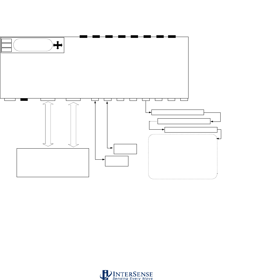
As shown in the block diagram in Figure 1, the IS-900 offers a wide range of tracking options.
InterSense’s SensorFusion code for calculating the full 6-DOF tracking solution is performed by
the dedicated IS-900 processor. The MicroTrax tracking devices and SoniStrips plug into the
serial interface ports and the IS-900 processor interfaces directly to a host computer via RS-232
serial port or Ethernet.
The IS-900 SimTracker supports a maximum of 4 MicroTrax devices and 12 SoniStrips (36
SoniDisc ultrasonic emitters). The IS-900 VETracker supports a maximum of 7 MicroTrax
devices and up to 42 SoniStrips (126 SoniDiscs) on an interface port. The VETracker can also
be configured to support 7 MicroTrax devices and up to 84 SoniStrips split between two interface
ports (42 SoniStrips or 126 SoniDiscs per port).
Figure 1 - IS-900 Functional Diagram
PORT1
RS-232 Port
Host
MicroTrax
Device
IS-900 SimTracker or IS-900 VETracker Processor
MicroTrax
Device
AC Power
& Switch
LCD Display with
Buttons
Ethernet Port
ETH
PORT2
PORT3
PORT4
PORT5
PORT6
PORT7
PORT8
Tracker and SoniStrip Ports*
PORT1
PORT2
PORT3
PORT4
PORT5
PORT6
PORT7
PORT8
LED Display of Active Ports
ENTER
F1
F2
*NOTE: IS-900 SimTracker Supports
only five Tracker/SoniStrip Ports
SoniStrip
SoniStrip
SoniStrip
- IS-900 SimTracker supports up to 12
SoniStrips (36 SoniDiscs)
- IS-900 VETracker supports up to 42
SoniStrips (126 SoniDiscs per port) & up to
84 SoniStrips per system (252 SoniDiscs)
- IS-900 VETracker requires an in-line Power
Booster for every 12 SoniStrips.
Host Computer or Graphics
Processor
InterSense IS-900 SimTracker & VETracker
Functional Block Diagram
InterSense Doc. No. 072-00105-0I07 Rev. 4.2
IS-900 User Guide Page 15 of 177
The IS-900 SimTracker and VETracker work with all of InterSense’s standard wired & wireless
MicroTrax devices (Head Tracker and Wand) plus several specialized devices developed for
OEM applications (Helmet Tracker, NVIS Virtual Binoculars & HMD, plus others).
Note that some early versions of InterSense’s devices are not compatible with the SimTracker &
VETracker components. Please check with InterSense Technical Support
(techsupport@intersense.com) to see if upgrades are required if you plan to use previously
purchased devices with the IS-900 SimTracker or VETracker system.
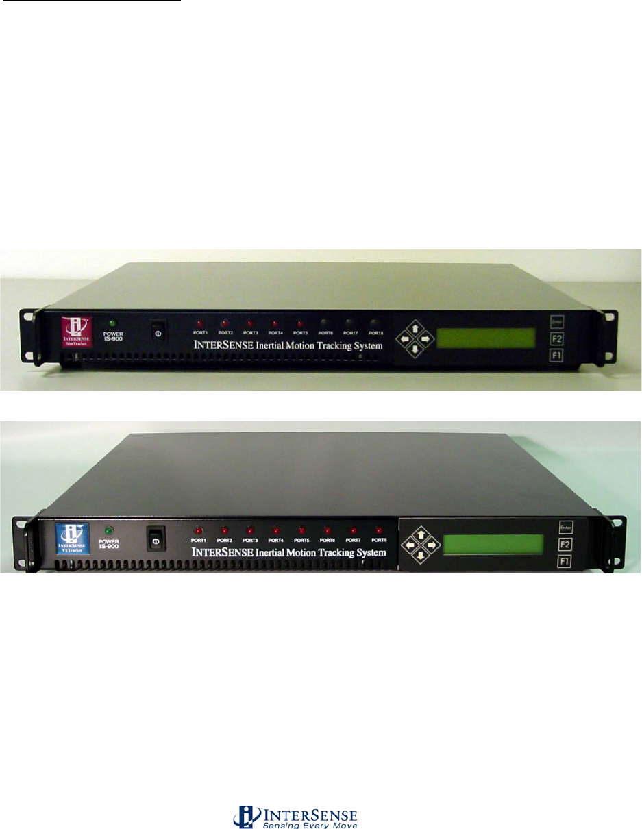
1.2. IS-900 SimTracker & VETracker Processor
The IS-900 Processor uses specialized firmware running on a dedicated processor to control
motion sensor data acquisition and then calculate tracking and related data for output over serial
or Ethernet interfaces. Shown in Figure 2, the SimTracker Processor has five front panel LEDs
which indicate active ports during normal operation. Shown in Figure 3, the VETracker
Processor has eight front panel LEDs to indicate active ports. Both processor configurations
have a front panel LCD display and selection buttons for checking and changing tracking system
parameters. The tracking device, SoniStrip, Ethernet, host computer, and power connectors are
accessed from the rear panel (described in detail in Section 3).
Figure 2 - IS-900 SimTracker Processor
Figure 3 - IS-900 VETracker Processor
InterSense Doc. No. 072-00105-0I07 Rev. 4.2
IS-900 User Guide Page 16 of 177
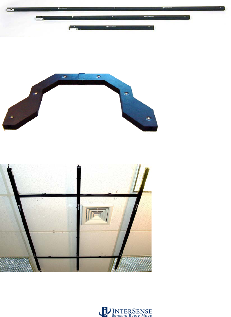
1.3. SoniStrips, SoniFrame, SoniWing & SoniPod acoustic
pulse transmitters
The SoniStrips (Figure 4), SoniWing (Figure 5), SoniFrame (Figure 6) and SoniPods (Figure 7)
have ultrasonic SoniDisc transmitters that receive addressed signals from the Base Processor
Unit and transmit ultrasonic pulses in response. The acoustic transmission beam width for each
SoniDisc is adjusted for wide-angle coverage (approx. 70-degree cone angle) to maximize the
tracking area.
Figure 4 - IS-900 SoniStrips
Figure 5 - IS-900 SoniWing
Figure 6 - IS-900 SoniFrame with three 6 ft. SoniStrips Assembled and Mounted on a
Ceiling
InterSense Doc. No. 072-00105-0I07 Rev. 4.2
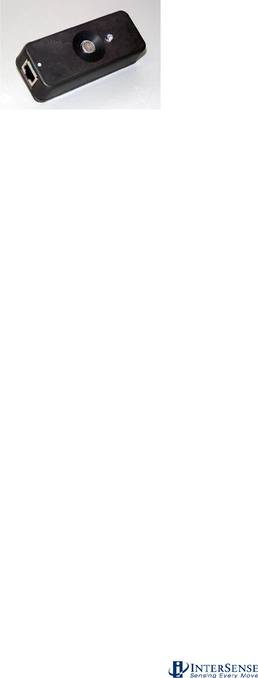
IS-900 User Guide Page 17 of 177
Figure 7 - Discrete SoniDisc Transmitter (SoniPod)
The IS-900 uses an acoustic time-of-flight (TOF) ranging system to prevent position and
orientation drift. For maximum accuracy and resolution, acoustic range measurements are made
with unidirectional TOF measurements from the SoniStrip transmitters to the Tracked Stations.
The SoniDiscs’ acoustic pulses are detected by miniature microphones integrated in the Tracked
Stations.
Details of the assembly and set up of the SoniFrame and SoniWing are found in a supplemental
manual in your IS-900 product CD.
1.4. Acoustic Constellation Mounting Considerations
The IS-900 product family offers a wide range of options to meet the needs of many different
tracking environments.
SoniStrips are normally mounted from the ceiling over the desired tracking workspace. To
increase the flexibility of this system, the IS-900 has been designed with different sized SoniStrips
for mounting in a variety of immersive environments. The user is able to position SoniStrips in
most environments, including confined spaces such as virtual workbenches, automobiles, and
cockpit simulators. Once installed, the user must calibrate the SoniStrip Constellation by
measuring the Cartesian X, Y, Z coordinates of each SoniStrip and enter this information using
the Constellation Configuration Utility Program provided with the system. A trained technical
representative should perform the process of calibration. InterSense provides installation
services and training upon request.
Adjusting the tracking volume is easily accomplished by selecting the appropriate ultrasonic
Constellation components. Options include different sized SoniStrips, discrete SoniPods and pre-
calibrated SoniFrame or SoniWing structures.
1.4.1. SoniFrame & SoniWing Fixed Constellations
The fixed frame SoniFrame assembly provides up to a 2 x 2 x 3 meter tracking volume with no
special sighting or calibration of the SoniStrips. The three SoniStrips easily mount to the
SoniFrame assembly to produce a repeatable rigid structure that is portable and convenient to
use. The SoniFrame provides a quick and convenient method for setting the IS-900’s tracking
area that does not require optical sighting for calibration.
The aluminum frame is made from a standard extrusion product that when assembled properly
will provide an accurate mounting platform for InterSense’s ultrasonic SoniStrip and SoniDisc
tracking referencing components.
InterSense Doc. No. 072-00105-0I07 Rev. 4.2
IS-900 User Guide Page 18 of 177
The design of the Fixed Frame provides mechanical mounting options for all InterSense
SoniStrips in all lengths (2-foot, 4-foot and 6-foot) and combinations. Figure 6 shows a typical
SoniFrame fully assembled and ceiling mounted with three 6 ft. SoniStrips.
Interconnect bars are available to assemble multiple SoniFrames together as one structure.
NOTE: When using multiple SoniFrames connected with InterSense’s interconnect bars, the fully
assembled & interconnected frames must be mounted to a rigid structure (i.e. a lighting grid or
ceiling structure). Furthermore, the mounted SoniFrames must be leveled and coplanar in order
to achieve accurate tracking.
The SoniWing is a smaller fixed frame assembly ideal for cockpit simulators or desktop tracking
applications. The SoniWing, like the SoniFrame, does not require special measurement or
calibration. The exact location of the SoniDiscs has been pre-measured by InterSense and is
included in the ISDEMO Constellation Tool utility program provided with the system. As with
SoniFrames, multiple SoniWings can be utilized with a single system (i.e. a dual cockpit flight
simulator configuration can use two SoniWings to simultaneously track two pilot head positions).
1.4.2. SoniPods
The SoniPod is a discrete SoniDisc packaged in its own enclosure with mechanical and electrical
interfaces. SoniPods provide the most flexible Constellation configuration option for closed
spaces, cockpits, or spaces that do not offer simple mounting spaces for fixed frames or
SoniStrips. Each SoniPod is connected by “daisy chain” to the next with one cable from the IS-
900 processor. It is highly recommended that InterSense installation engineers are consulted for
configuration, installation and calibration of an IS-900 SoniPod Constellation array.
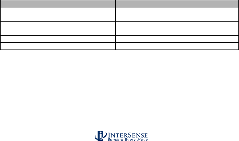
1.5. Tracking Station Description
For InterSense motion tracking systems, a “station” is the tracked object or device, which by
industry jargon may also be called a sensor or tracker. An IS-900 tracks all stations in a 6-DOF
mode, meaning each tracked device outputs X, Y, Z position information along with a pitch, yaw
and roll orientation information. In addition, the Wand Tracking Station output joystick and button
information for use with the immersive environment software. Figure 8 summarizes InterSense’s
IS-900 Tracking Stations.
Tracked Station
Function
MicroTrax Wand w/ Joystick Tracking
Station
Five button with center push button joystick
MicroTrax Head Tracking Station
Stereo glasses and Head Mounted Display
(HMD) mounted
MicroTrax Hand Tracking Station
Mounted to user’s hand
MicroTrax OEM Tracking Stations
Specific to OEM application
Figure 8 - IS-900 Tracked Stations
Each tracked station sends inertia measurement unit (IMU) data (angular & acceleration rates)
with Ultrasonic Receiver Module (URM) acoustic range data for transmission to IS-900 base
processor via wired or wireless links.
InterSense provides the different types of tracked stations listed above for use in immersive
environments. All of these tracked stations use InterSense’s advanced inertial MicroTrax
technology combined with miniaturized digital acoustic position referencing components.

InterSense Doc. No. 072-00105-0I07 Rev. 4.2
IS-900 User Guide Page 19 of 177
In addition to InterSense’s standard tracked stations, there are also new OEM devices being
delivered with some IS-900 systems that integrate the IS-900 technology into custom 3rd party
tracked stations. IS-900 systems shipped with 3rd party devices come with documentation
specific to these devices.
All of InterSense’s MicroTrax tracking devices can be configured with a wireless transmitter &
receiver for unencumbered tracking over larger areas.
The following sections summarize all of the options available from your local reseller or
InterSense.
InterSense Doc. No. 072-00105-0I07 Rev. 4.2
IS-900 User Guide Page 20 of 177
1.5.1. MicroTrax Wand with Joystick
Figure 9 - MicroTrax Wand
The MicroTrax Wand with center-click Joystick (Figure 9) is a tracked device that provides a
simple and convenient way for the user to interact with virtual environments.
There are four miniature acoustic receiver microphones integrated into the MicroTrax Wand.
During operation, all four miniature microphones are sampling the ultrasonic signals. Based on
the trackers position with respect to ultrasonic Constellation array, only signals from the two best
microphones are used for combination with the inertial data and calculation of the 6-DOF output.
Each miniature receiver microphone has a reception cone angle approaching 180°. With two
pairs of microphones located on the top and bottom of the MicroTrax Wand, the wand will
consistently track over a full 360° range of motion in all axes while under the active Constellation
array. The Wand will continue to track during brief (less than 1 minute) occlusion of one of the
two active microphones.
Each of the five buttons (four on top and one below plus sixth button on the joystick can be
accessed from the IS-900 data stream by calling the output record Data Item 22. The two axis
analog joystick provides an easy “fly-through” navigation interface used in most immersive virtual
environments. The access to joystick data comes by calling the output record Data Item 23.
The device powers on by pressing the left button for ~ 3seconds. The unit will auto-off after 10
minutes of no movement to preserve battery power. To shut the unit off, press the left button and
right button simultaneously (pressing the left button for ~ 1 minute will also power off the device).
Details of format, definition, and programming your application to use the buttons and joystick can
be found in Section 4.

InterSense Doc. No. 072-00105-0I07 Rev. 4.2
IS-900 User Guide Page 21 of 177
1.5.2. MicroTrax Head Tracker
Figure 10 - MicroTrax Head Tracker
The MicroTrax Head Trackers (Figure 10) are tracked devices that provide accurate 6-DOF data
needed to give the user a correct visual viewpoint in an immersive visual environment. The
MicroTrax head tracker is suitable for use in both projected (Simulators, CAVE®s, PowerWalls,
etc…) and head worn (HMDs) application where head tracking is required.
The device can be used wired, or wirelessly. When wired, the head tracker connects to the
MicroTrax TTL-RS422 Dongle. When used in a wireless configuration the head tracker connects
to the MicroTrax Wireless Transmitter. The transmitter powers on by pressing the button for ~
3seconds. The unit will auto-off after 10 minutes of no movement to preserve battery power. To
shut the unit off, press and hold the button for 3 seconds.
There are two miniature acoustic receiver microphones integrated into the MicroTrax Head
Tracker. During operation, all miniature microphones are sampling the ultrasonic signals. Each
miniature receiver microphone has a reception cone angle approaching 180°.
The MicroTrax Head Tracker has the receiver microphones placed at a 45° angle off the front of
the device assuring continual tracking with all normal head positions in standard ceiling or wall
mounted Constellation arrays. The head trackers will continue to track during brief (less than 1
minute) occlusion of one of the microphones.
InterSense Doc. No. 072-00105-0I07 Rev. 4.2
IS-900 User Guide Page 22 of 177
1.5.3. MicroTrax Docking Station
Figure 11 - MicroTrax Docking Station
The MicroTrax Docking Station (Figure 11) is an optional component that serves to hold the
wireless MicroTrax devices, and two spare batteries, in one handy place. The wireless devices
are equipped with charging contacts enabling recharging in-situ. LEDs next to each slot indicate
when the device is in the process of charging or is completely charged. When the LED is
illuminated and the color is:
• Orange Device is in the process of recharging
• Green Device is fully charged.
• Off Device is either not fully seated or the docking station is not powered.
InterSense Doc. No. 072-00105-0I07 Rev. 4.2
IS-900 User Guide Page 23 of 177
1.5.4. MicroTrax Hand Tracker
Figure 12 - MicroTrax Hand Tracker
The MicroTrax Hand Tracker (Figure 12) is a tracked device that provides accurate 6-DOF data
of a user’s hand. The MicroTrax Hand Tracker is designed to be ambidextrous. When properly
mounted to either hand, the main device cable should exit the tracker from the pinky-side of the
hand.
The device can be used wired, or wirelessly. When wired, the hand tracker connects to the
MicroTrax TTL-RS422 Dongle. When used in a wireless configuration the hand tracker connects
to the MicroTrax Wireless Transmitter. The transmitter powers on by pressing the button for ~ 3
seconds. The unit will auto-off after 10 minutes of no movement to preserve battery power. To
shut the unit off, press and hold the button for 3 seconds.
There are four miniature acoustic receiver microphones integrated into the MicroTrax Hand
Tracker. During operation, all four miniature microphones are sampling the ultrasonic signals.
Based on the tracker’s position with respect to ultrasonic Constellation array, only signals from
the two best microphones are used for combination with the inertial data and calculation of the 6-
DOF output. Each miniature receiver microphone has a reception cone angle approaching 180°.
The head tracker will continue to track during brief (less than 1 minute) occlusion of one of the
two active microphones.

InterSense Doc. No. 072-00105-0I07 Rev. 4.2
IS-900 User Guide Page 24 of 177
1.5.5. Wireless MicroTrax Modules
All MicroTrax tracked stations can be operated without cabling to the IS-900 processor by using
the IS-900 Wireless Modules. The Wireless Modules have two components—a receiver
component that plugs into the IS-900 Processor and a rechargeable, battery operated transmitter
that is either integrated into the tracked station (e.g. IS-900 Wireless MicroTrax Wand), or
connected to a small, body worn transmitter that plugs directly in to the MicroTrax Station (e.g. IS-
900 Wireless MicroTrax Head Tracker).
1.5.6. OEM Tracking Devices
InterSense works with Value Added Resellers, Systems Integrators and Partners to provide
tracked devices tailored to specific applications. InterSense uses the Inter-IC bus (I2C) interface
to all MicroTrax devices. The I2C is an industry standard interface developed by Philips nearly 20
years ago to establish a simple 2-wire communication standard between a variety of IC’s and
interface devices.
By choosing this standard board level interface, OEM’s and systems integrators have the
flexibility of integrating the InterSense’s IS-900 wireless tracking technology and device interface
into custom 3D interaction devices. InterSense can assist you with the development of a custom
device, providing technical interface details and reference designs, or be contracted to develop
the custom device to your specifications. For additional information about custom system
development, call or email us at sales@intersense.com.
InterSense Doc. No. 072-00105-0I07 Rev. 4.2
IS-900 User Guide Page 25 of 177
1.6. IS-900 Cables, Connectors, Adaptors, Power
Boosters and Wireless Radios
Due to the flexible design of the IS-900 system, many systems are custom configured and
installed by trained service representatives and may come with varying cabling and interconnect
items.The items and their descriptions in this section cover all standard and optional interconnect
components available for the IS-900.
Contact InterSense for detailed cable, adapter, or power booster specifications/questions.
1.6.1. Wired System
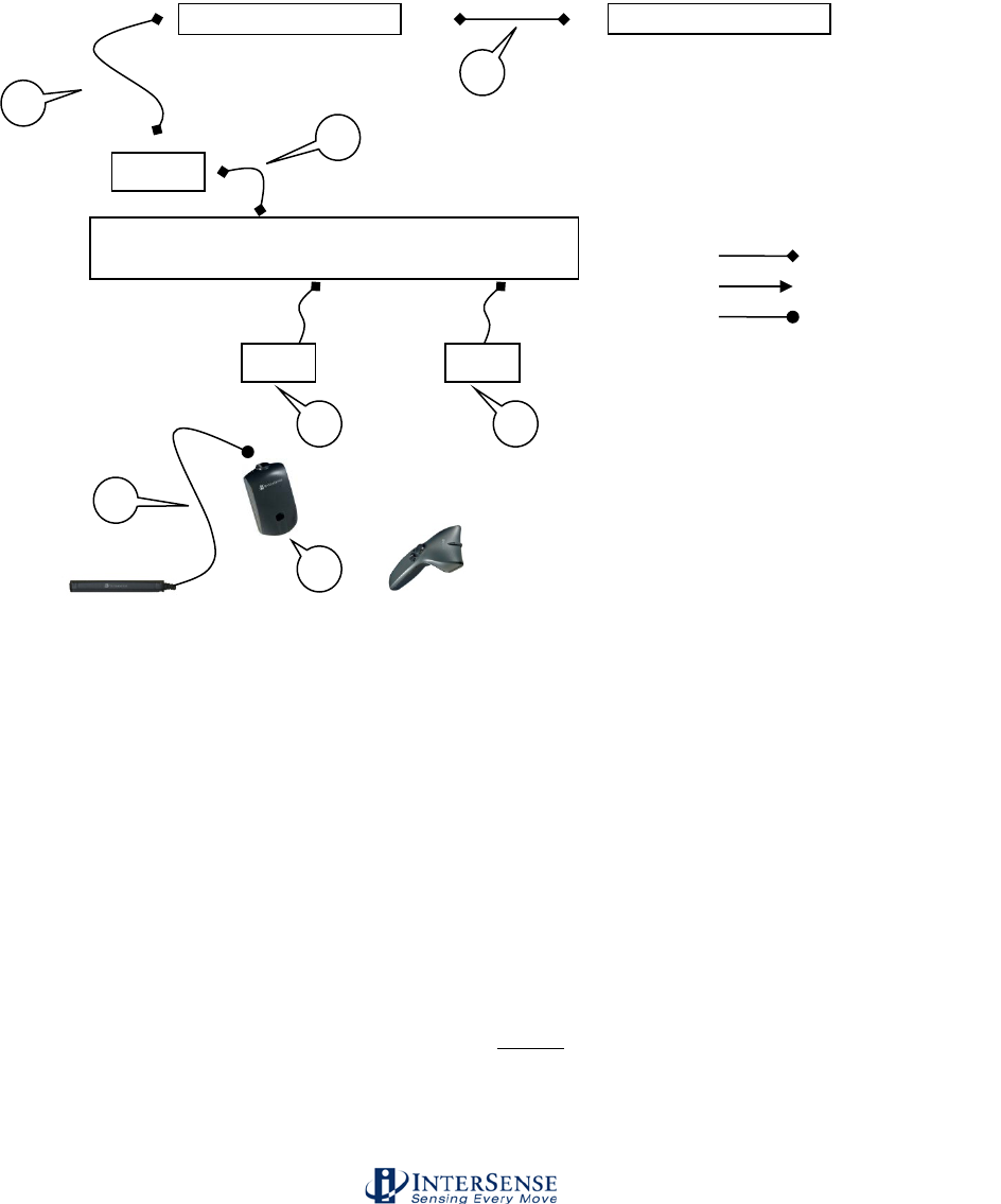
Figure 13 illustrates how the cables, connectors and adaptors are set-up for the wired version of
the IS-900 System and MicroTrax devices.
Figure 13 - Wired IS-900 and MicroTrax Cables, Connectors and Adapters
SoniStrip*
SoniStrip*
1
2
IS-900 Processor
Head Tracker
Not – to - Scale
Adapter
RJ48
RJ12
Hirose
Connector Symbols
Wand
Adapter
3
4
5
6
1
1
*Configuration
depends on your
constellation

InterSense Doc. No. 072-00105-0I07 Rev. 4.2
IS-900 User Guide Page 26 of 177
1. Cable: Processor to SoniStrip or to MicroTrax device Adapter.
• Part no. 078-00088-0030
• 30 feet long
• RS422 communication
• 10-pin RJ48 cable connector
This 30 foot cable provides basic +12 VDC power and transmits the SoniDisc trigger signals to
the SoniStrip Constellation array. It connects from the back of the IS-900 Processor (any PORT
#) to the SoniStrips and can run a maximum length of 15 meters (50 ft.)*.
*NOTE: Maximum length of the total SoniStrip daisy chain measured from the IS-900 Processor
to the end of the SoniStrip chain is 24 meters (80 ft.) without external power boosters.
This same cable is also used to connect the MicroTrax adapter to the processor.
2. Cable: SoniStrip to SoniStrip
• Part no. 078-00088-0004
• 4 feet long
• RS422 communication
• 10-pin RJ48
The 4 foot SoniStrip to SoniStrip cable provides standard connectivity between each SoniStrip in
the Constellation array. The cable and connector type (10-pin RJ48) are identical to the
Processor to SoniStrip Cable. The IS-900 SimTracker configuration can support a maximum of
12 SoniStrips (36 SoniDiscs) per system. The IS-900 VETracker configuration can support 84
SoniStrips (252 SoniDiscs) split between two ports with the use of external power boosters**.
**NOTE: Maximum length of total SoniStrip daisy chain measured from the IS-900 Processor to
the end of the SoniStrip chain and configured with power boosters can be greater than 90 meters
(300 ft.). Consult with InterSense for non standard configuration support!
3. Cable (Integral to the Head Tracker): Head Tracker to Adapter (ref. item 4)
• Part no. 100-91003-AWHT
• 3 feet long
• TTL communication
• Hirose connector
In order to keep the Head Tracker lightweight and unobtrusive, we use a Hirose connector
carrying a TTL signal. However this cable has limited length to processor capability. Therefore,
we convert it to anRS422 signal to allow longer cable lengths.
4. Adapter: TTL to RS422
• Part no. 100-91000-AWDG
• Hirose Connector for TTL
• 10 pin RJ48 connector for RS422
This adapter simply converts the TTL MicroTrax interface signals to a differential serial signal
(RS422) in order to transmit the signals long distance to the IS-900 Processor. The interface
RJ48 connector labeled “BASE” attaches to the Cable (ref. item 1). The Hirose connector
connects directly to the MicroTrax Head Tracker integral cable (ref. item 3).
5. Cable (Integral to Wand): Wand to Adapter (ref. item 6)
• Part no. 100-91012-AWWD
• 12 feet long
• RS232 Communication
• 6-pin RJ-11
This cable is fixed to the wand and uses RS232 communication. It has limited length capability
therefore must be converted to an RS422 signal to allow for longer cable lengths.downstream
closer to the processor.

InterSense Doc. No. 072-00105-0I07 Rev. 4.2
IS-900 User Guide Page 27 of 177
6. Adapter: RS232 to RS422
• Part no. 100-SDPDL-001
• 10 pin RJ48 connector for RS422
• 6-pin RJ12 connector for RS232
This adapter simply converts the RS232 MicroTrax interface signals to a differential serial signal
(RS422) in order to transmit the signals long distance to the IS-900 Processor. The interface
RJ48 connector labeled “BASE” attaches to the Cable (ref. item 1). The RJ12 connector labeled
“TRACKER” connects to the MicroTrax Wand integrated cable.
InterSense Doc. No. 072-00105-0I07 Rev. 4.2
IS-900 User Guide Page 28 of 177
1.6.2. Wireless System
Figure 14 illustrates how the cables, connectors and adaptors are set-up for the wireless version
of the IS-900 System and MicroTrax devices. For simplicity, 2.4 GHz wireless devices are
shown, therefore each device requires its own receiver (900 MHz devices may share
receivers, 2 devices per receiver).
Figure 14 - Wireless IS-900 and MicroTrax Cables, Connectors and Adapters
1. Cable: Processor to SoniStrip
• Part no. 078-00088-0030
• 30 feet long
• RS422 communication
• 10-pin RJ48 cable connector
This 30 foot cable provides basic +12 VDC power and transmits the SoniDisc trigger signals to
the SoniStrip Constellation array. It connects from the back of the IS-900 Processor (any PORT
#) to the SoniStrips and can run a maximum length of 15 meters (50 ft.)*.
*NOTE: Maximum length of the total SoniStrip daisy chain measured from the IS-900 Processor
to the end of the SoniStrip chain is 24 meters (80 ft.) without external power boosters.
SoniStrip*
SoniStrip*
1
2
IS-900 Processor
Head Tracker
Not – to - Scale
RJ48
RJ12
Hirose
Connector Symbols
Wand
3
7
* Configuration
depends on your
constellation
WR
WR
8
8
ATA
9

InterSense Doc. No. 072-00105-0I07 Rev. 4.2
IS-900 User Guide Page 29 of 177
2. Cable: SoniStrip to SoniStrip
• Part no. 078-00088-0004
• 4 feet long
• RS422 communication
• 10-pin RJ48
The 4 foot SoniStrip to SoniStrip cable provides standard connectivity between each SoniStrip in
the Constellation array. The cable and connector type (10-pin RJ48) are identical to the
Processor to SoniStrip Cable. The IS-900 SimTracker configuration can support a maximum of
12 SoniStrips (36 SoniDiscs) per system. The IS-900 VETracker configuration can support 84
SoniStrips (252 SoniDiscs) split between two ports with the use of external power boosters**.
**NOTE: Maximum length of total SoniStrip daisy chain measured from the IS-900 Processor to
the end of the SoniStrip chain and configured with power boosters can be greater than 90 meters
(300 ft.). Consult with InterSense for non standard configuration support!
3. Cable (Integral to the Head Tracker): Head Tracker to MicroTrax Wireless Transmitter (ref.
item 7)
• Part no. 100-91003-AWHT
• 3 feet long
• TTL communication
• Hirose connector
7. MicroTrax Wireless Transmitter for Head Tracker
• Part no. 100-91000-EWTX
This module transmits the data from the wireless head tracker to the head tracker’s receiver.
The Hirose connector attaches to the TTL cable integral to the head tracker.
8. MicroTrax Wireless Receiver
• Part no. 100-IS9MW-RX16
• Has integral cable that connects to the processor
• RS422 communication
• 10-pin RJ48 cable connector
9. Cable for Acoustic Timing Adjuster
• Part no. 078-00088-0001
• 1 foot long
• RS422 communication
• 10-pin RJ48 cable connector
• Adjusts the timing of the beacons in the SoniStrips to match the timing of the MicroTrax
wireless devices.
InterSense Doc. No. 072-00105-0I07 Rev. 4.2
IS-900 User Guide Page 30 of 177
1.6.3. All Systems
AC Power Cable, Part No. 078-00003-xx09 (“xx” for US/JP, UK, EU country code)
The IS-900 system ships with a 9 foot AC Power Cord to match the country voltage specification
on your order. The IS-900 Processor has an auto switching power supply module to supporting
AC voltage inputs from 100 to 240 VAC.
RS-232 Null Modem Serial Cable, Part No. 078-00001-0000 (IS-900 Processor to PC cable)
The null modem cable provides both data and control communication between the IS-900 System
and your host computer. InterSense ships a 1.8 meter (6 foot) cable with the system. The
maximum specified length for RS-232 communication cabling is 7.6 meters (25 feet). A pin-out
and cable specification is located in FAQ’s Appendix below. The null modem cable connects to
the port labeled HOST on the IS-900 Processor.
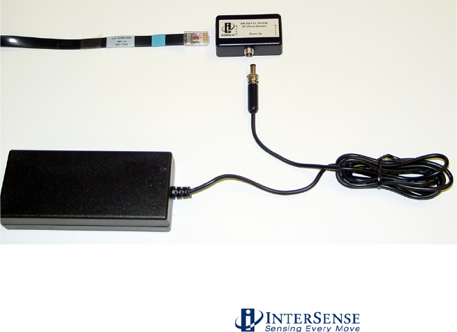
(Optional) SoniStrip Power Booster, Part No. ISC-REV3X-PWRx
The optional SoniStrip Power Booster kit shown in Figure 15 comes with a +15 VDC power
supply w/ country specific line cord, a 4 ft. SoniStrip Cable (Part No. 078-00088-0004), and an in-
line power booster module (Part No. 100-REV3X-POWR). SoniStrip Power Booster Kits are
required for SoniStrip Constellation Arrays that meet at least one the following conditions:
a) The initial Processor to SoniStrip Cable, Part No. 078-00088-00xx, is greater than 15
meters (50 ft.).
b) The SoniStrip Constellation Array is configured with more than 12 SoniStrips.
c) Any SoniStrip Constellation array requires an extended measurement range of up to 4
meters (13 ft.).
For condition (a) with just 12 SoniStrips in a Constellation Array, the Power Booster is inserted in-
line with the SoniStrip just before the first SoniStrip in the array. For condition (b), a Power
Booster is required after every 12th SoniStrip in a Constellation (i.e. it is added in-line after
between the 12th and 13th SoniStrip, the 24th and 25th SoniStrip, etc…). For condition (c), the
Power Boosters deploy as in-line components before the 1st SoniStrip and after every 12th
SoniStrip thereafter.
Figure 15 - SoniStrip Power Booster (Optional)

InterSense Doc. No. 072-00105-0I07 Rev. 4.2
IS-900 User Guide Page 31 of 177
Failure to power down the IS-900 Processor when connecting or disconnecting
tracked stations will cause damage to the tracked stations.
Exceeding maximum cable lengths will cause IS-900 to operate unreliably due
to signal transmission and timing errors.
1.7. IS-900 Support CD
The provided support CD has the latest version of all InterSense product specifications,
InterSense technical papers/notes, and IS-900 product documentation. The current version of
InterSense’s ISDEMO set-up, calibration, and product testing software is also available on the
support wepage at http://www.intersense.com/downloads.

InterSense Doc. No. 072-00105-0I07 Rev. 4.2
IS-900 User Guide Page 32 of 177
2. Specifications
2.1. Performance Specifications
Degrees of Freedom: 6 (X, Y, Z, Yaw, Pitch, and Roll)
Tracking Device(s): MicroTrax Head Tracker
MicroTrax Wand
MicroTrax Hand Tracker
Custom/OEM Devices (Consult InterSense)
Tracking Volume: Up to 20 m2 with 12 SoniStrips (SimTracker maximum)
Up to 140 m2 with 84 SoniStrips (VETracker maximum)
2.0 m x 2.0 m x 3.0 m maximum w/ SoniFrame (optional)
1.5 m x 1.5 m x 3.0 m with SoniWing (optional)
Angular Range: Full 360º - All Axes
Resolution: 0.75 mm (1.5 mm Wireless)
0.05º (0.10º Wireless)
Static Accuracy: 2.0 to 3.0 mm (3.0 to 5.0 mm Wireless)
0.25º RMS in Pitch & Roll, 0.50º RMS in Yaw
0.50º RMS in Pitch & Roll, 1.00º RMS in Yaw (Wireless
MicroTrax)
Update Rate: 180 Hz Nominal
120 Hz Minimum (Wireless SimTracker & VETracker)
Latency: 4 ms Typical (without prediction @ 115 kbaud)
Maximum number of devices 4 for SimTracker (Wired or Wireless)
7 for VETracker (Wired or Wireless)
Interface: RS-232 Serial Port
Ethernet
O/S Compatibility: Windows XP/Vista/7, Linux, Mac OS X
Software Support: SDK with full InterSense API
ISDEMO control & connectivity software
2.4 GHzSpecification for Wireless Devices
Device charge time 3 hours
Number of charges 500
Constant Tracking Time 6-8 hours on one charge
Radio Technology 2.4 GHz non-frequency hopping spread spectrum
Radio Range (Indoor) 100 Feet (with no major obstructions)
Radio Channels 16

InterSense Doc. No. 072-00105-0I07 Rev. 4.2
IS-900 User Guide Page 33 of 177
900 MHzSpecification for Wireless Devices
Device charge time 3 hours
Number of charges 500
Constant Tracking Time 6-8 hours on one charge
Radio Technology 900 MHz non-frequency hopping spread spectrum
Radio Range (Indoor) 100 Feet (with no major obstructions)
Radio Channels 10
2.2. Physical Specifications
AC Input: 100 to 120 V/200 to 240 V, 60/50 Hz, 6/3 A (auto switching)
Operating Temperature: 0º C to 50º C (32º F to 122º F)
Storage Temperature: -20º C to 70º C (-4º F to 158º F)
Standard Cable Lengths: IS-900 to SoniStrips – 10.7 m
IS-900 to Tracking Devices – 12.0 m
IS-900 to Host (RS-232 Serial) – 1.8 m
Maximum Cable Lengths: System configuration dependent – Consult InterSense
Processor Size: 1 U rack mounted (44.45 cm wide x 40.64 cm deep x 4.45
cm tall)
Processor Weight: 6.8 kg
SoniStrip Size Weight
2 foot 0.61 m x 3.7 cm x 2.5 cm 0.4 kg
4 foot 1.22 m x 3.7 cm x 2.5 cm 0.9 kg
6 foot 1.83 m x 3.7 cm x 2.5 cm 1.3 kg
MicroTrax Devices Size (outside dimensions) Weight
Standard Head Tracker 10.15 x 1.54 x 1.38 cm 40 g (Includes wire)
Wired Wand 17.48 x 10.16 x 5.38 cm 140 g
Wireless Wand 17.48 x 10.16 x 5.38 cm 170 g
Wireless Transmitter 7.62 x 4.45 x 3.40 cm 65 g
Wireless Receiver 5.3 x 3.5 x 2 cm 45.4g (includes wire)
InterSense Doc. No. 072-00105-0I07 Rev. 4.2
IS-900 User Guide Page 34 of 177
2.3. Environmental Specifications
When disposing of electronic equipment please do so responsibly in accordance with local
requirements.
Normal environmental conditions
This standard applies to equipment designed to be safe at least under the following conditions:
a) indoor use;
b) altitude up to 2 000 m;
c) temperature 0 °C to 50 °C;
d) maximum relative humidity 80 % for temperatures up to 31 °C decreasing linearly to 50 %
relative humidity at 40 °C;
e) MAINS supply voltage fluctuations up to ±10 % of the nominal voltage;
f) transient over voltages typically present on the MAINS supply.
g) Applicable rated pollution degree 2 environment.
10
ISO 7000-0434
Attention, consult accompanying documents
In case of application as a safety sign, the rules according to ISO 3864
-1 are
to be adhered to.
See safety sign ISO 3864-1, B.3.1, “General warning,
caution, risk of danger”.
3. Installation and Set-up
This section reviews the background information needed to understand how the IS-900 system
works. It then covers the detailed steps required for set-up and calibration of the IS-900 tracking
system in typical virtual or simulation environments. References made to other parts of this
manual or to supplemental manuals provide additional background material.
The detailed set-up steps below assume an IS-900 VETracker is being used for a typical
immersive display environment with a wired MicroTrax Head Tracker and a wired MicroTrax
Wand. Systems purchased for different applications, such as cockpit simulators, may require
technical support from InterSense to complete the installation, although the basic steps covered
here are applicable for all IS-900 tracking configurations.
Check IS-900 Firmware Version
Tracking device upgrades to an existing IS-900 System may require you to upgrade the firmware
in the IS-900 Processor.
Wireless Tracking Modules with the IS-900 SimTracker or VETracker processors require firmware
version 4.20 or later (MiniTrax), 4.2301 or later (MicroTrax), or 4.29 or later (900 MHz wireless) to
operate.
To check if your IS-900 system needs a firmware upgrade, follow these steps:

InterSense Doc. No. 072-00105-0I07 Rev. 4.2
IS-900 User Guide Page 35 of 177
1. Power on the IS-900
Shortcut
→
Use the front panel buttons and LCD menus to determine the IS-900 firmware
version by pressing the Enter key, arrow key down to System Config, select Enter again,
select Information to read Firmware revision number. Or use ISDEMO as follows.
2. Connect the PC to the IS-900 processor using the null modem cable provided with your
system or via Ethernet.
3. Launch ISDEMO to determine the firmware version installed in the IS-900 Processor
(with ISDEMO, this information is found under the Tools→System Information menu).
4. If the version number shown is lower than the version specified above for your IS-900
processor configuration, you will need to upload a new version of firmware to the IS-900
processor.
If you believe you require a Firmware Upgrade for the IS-900 System, please contact
InterSense Technical (techsupport@intersense.com or +1 781 541-7624) support for
assistance with selecting the correct firmware needed with your system. The necessary
download and instructions can also be found on the Support section of our website.
InterSense Doc. No. 072-00105-0I07 Rev. 4.2
IS-900 User Guide Page 36 of 177
3.1. InterSense Coordinate Reference Frame
Before setting up the IS-900, it is important to review the standard InterSense coordinate
reference system. As a 6-DOF tracker, use of the “InterSense Coordinate Reference Frame”
throughout this manual helps explain the installation, calibration and tracking performance.
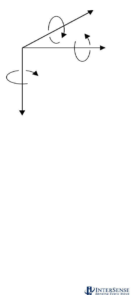
Figure 16 - InterSense Coordinate Reference Frame
Figure 16 shows the standard reference frame for both position and orientation of all InterSense
tracker systems.
The reference frame (hereafter referred to as Navigation frame or Nav frame or N frame) is the
locally-level geographic frame with its x-axis pointing north, y-axis east, and z-axis down.
It is important to understand that when setting up any InterSense system, the z-axis of the
tracking system’s coordinates must always point in the direction of gravity, whereas the x
and y axes may be set to any direction rotated about the z-axis.
Subsequent coordinate transformations by application software to change the direction of the z-
axis are normal, but the underlying reference of InterSense’s inertial components to gravity must
be maintained by the tracking system. The Euler angles reported by the tracker are described as
a sequence of rotations applied to the tracking device starting with its body axes initially aligned
with the Nav frame axes and resulting in the current orientation. The sequence starts with a
rotation by (+yaw) about the Z axis, followed by a rotation by (+pitch) about the new Y axis (i.e.
body frame axis), followed by a rotation by (+roll) about the new X axis (i.e. body frame x axis).
Yaw
Roll
Pitch
X
Y
Z

InterSense Doc. No. 072-00105-0I07 Rev. 4.2
IS-900 User Guide Page 37 of 177
3.2. Hardware Set-up
General Equipment Handling Warnings
The ultrasonic transmitters (SoniDiscs) are sensitive electronic
components. Take care not to allow any dirt or moisture in or around the
SoniDiscs install the SoniStrips, SoniFrame, SoniWing or SoniPods.
Mishandling or static discharge can damage both the ultrasonic emitters
and the tracking devices.
Do not drop the tracked stations. While InterSense has designed the
devices for normal usage in simulators and virtual environments,
excessive shock can damage the internal components.
Always turn off the IS-900 Processor (remembering to save any
configuration changes) before plugging or unplugging the tracked
stations. Failure to do this could result in damage to the stations.
Always store the tracked devices in a secure location when not in use.
Leaving them on the floor or on an unsecured surface can result in
accidental damage.
This section covers a typical installation of the IS-900 with standard components. Consult
InterSense for non-standard or OEM installations.
The basic steps covered in this section include:
• Installation of SoniStrips
• Mount and Calibration of SoniStrips
• Connection and Test with the IS-900 Processor.
• Special Instructions for Wireless Devices
Unpack all components and check against packing list (standard configuration referenced in
Section 1.2 for the IS-900 SimTracker and 1.3 for the IS-900 VETracker). Check the packing list
that came with the system as many orders will not match the standard configurations shown in
Section 1. Contact InterSense if any components are missing or appear damaged.
InterSense Doc. No. 072-00105-0I07 Rev. 4.2
IS-900 User Guide Page 38 of 177
3.3. Installation of SoniStrips
In order to install the SoniStrips, you need the following (that are not supplied in the standard IS-
900 System):
1. An optical surveying tool or Total Station. We recommend a Nikon DTM 420 or equivalent for
measuring absolute X, Y, and Z coordinates of all SoniDiscs.
Note: If your IS-900 system comes with a fixed constellation frame (SoniFrame or
SoniWing), then the optical surveying equipment is not needed.
2. A Windows PC capable of running the latest version of ISDEMO (check
www.intersense.com/downloads.aspx for current version).
General Guidelines
The position of a SoniDisc is defined as the coordinates of the center of the grill covering the
speaker. When measuring the position of each SoniDisc in an installed Constellation Array, all
values are entered in meters. The coordinates of the SoniDiscs are entered in a user-defined,
locally leveled coordinate frame. The coordinate system is right-handed with X pointing forward,
Y to the right and Z pointing down. Position data for all stations is computed relative to that
coordinate system.
SoniStrips come in 0.6, 1.2 or 1.8 meter (2, 4 or 6 foot) lengths. The 2-ft. SoniStrip has two
SoniDiscs per SoniStrip and the 4-ft SoniStrip has 3 SoniDiscs installed with each SoniDisc
spaced at 0.61 m (2 foot). The 6-ft SoniStrip has 3 SoniDiscs with each spaced at 0.91 m (3 foot)
spacing. For best performance, it is generally recommended that SoniStrips be installed in a
regular grid over the tracked area. Total distance from a SoniDisc in the Constellation to a
tracked station should not exceed 3.0 meters (10 feet) to guarantee good signal detection (4
meters with external power boosters installed).
IS-900 default configuration does not contain a Constellation, so it is up to the user to configure it.
To properly track, the system needs to know the position and orientation of each of the SoniDiscs
in the Constellation with high degree of accuracy. The best way to measure position of each
SoniDisc is with the use of an optical sighting tool known as a Total Station. The quality of the
measured position data input for the SoniStrip Constellation Array is directly proportional to the
accuracy of the IS-900 system’s tracking data output.
A second parameter needed for each SoniDisc in the installed Constellation Array is the unit
normal vector, as shown in Figure 17. The unit normal vector defines the orientation of a
SoniDisc. The default assumption is that the Constellation is installed horizontally over the
tracked area, so the normal vector points straight down with unit normal vector coordinates of 0,
0, 1. The unit normal vector is the same for each SoniDisc on the same SoniStrip. Entering the
correct normal vector for each SoniDisc is important. The normal vector information is used by
the IS-900 tracking algorithm to correctly schedule the polling of each SoniDiscs.
Figure 17 - Unit Normal Vector Definition for Ceiling Installed SoniStrip
Normal vector pointing down
0, 0, 1
SoniStrips
SoniDisc Emitter
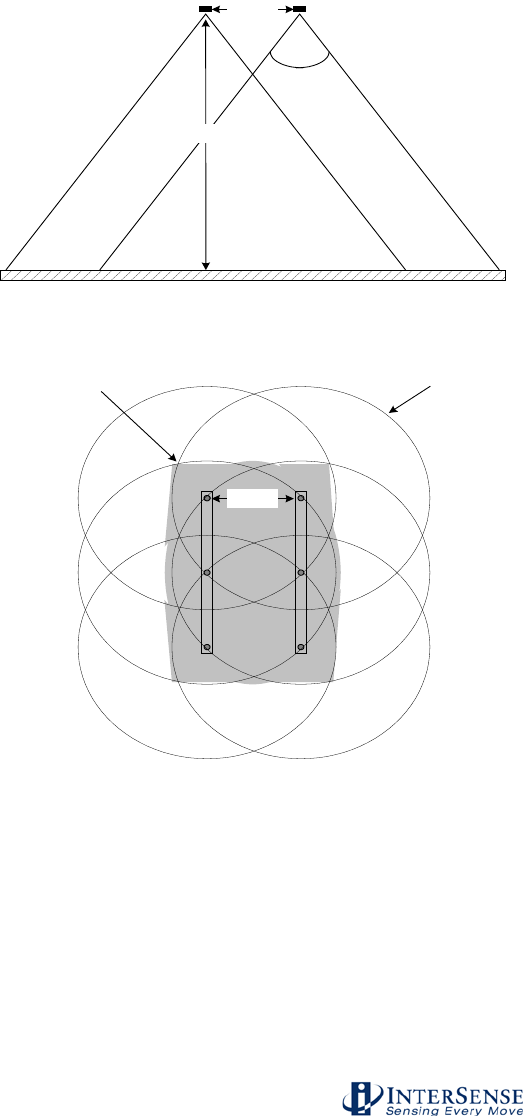
InterSense Doc. No. 072-00105-0I07 Rev. 4.2
IS-900 User Guide Page 39 of 177
The SoniStrip Constellation Array provides an absolute positional reference to the tracked
environment. The idea behind providing SoniDiscs (beacons) in groups of three in each SoniStrip
(rail) is to give flexibility in both the configuration and installation to cover a wide range of tracking
environments in a convenient package for ease of installation. To establish a minimum criterion
for a tracked environment, at least two SoniStrips are required to provide proper tracking. A
conceptual diagram using two SoniStrips, shown in Figure 18, provides the fundamental
relationship established by the SoniStrip Constellation with respect to the tracking environment.
0.67 m
3 m
Side view of SoniStrips
Area of Single SoniDisc
Coverage at 2 m from
SoniStrip Constellation
Area of optimal
tracking at 1m to 2 m from
SoniStrip Constellation
Top view of SoniStrips
70 degree
acoustic cone
Floor
0.67 m
Figure 18 - Tracking Coverage with Two SoniStrips
When preparing the installation for SoniStrips or SoniPods, it is very important to assure the
following in order to maintain stable tracking conditions:
1. The mounting surface is rigid and stable
2. The relative position between SoniStrips or SoniPods remains fixed

InterSense Doc. No. 072-00105-0I07 Rev. 4.2
IS-900 User Guide Page 40 of 177
Note: If either of these two conditions is not met, then the performance of the tracking
system will degrade and possibly fail. InterSense will not warrant a system to track with
improper installation.
For larger or first time installations, we recommend you contract InterSense to perform on-
site installation and training. Please contact your InterSense representative for details.
Sections 3.3.1, 3.3.2 and 3.3.3 describe three examples of typical tracking system installations:
• SoniStrip Mounting for Ceiling Installations
• SoniStrip Mounting for Power Wall Installations
• SoniStrip Mounting for CAVE-like Installations
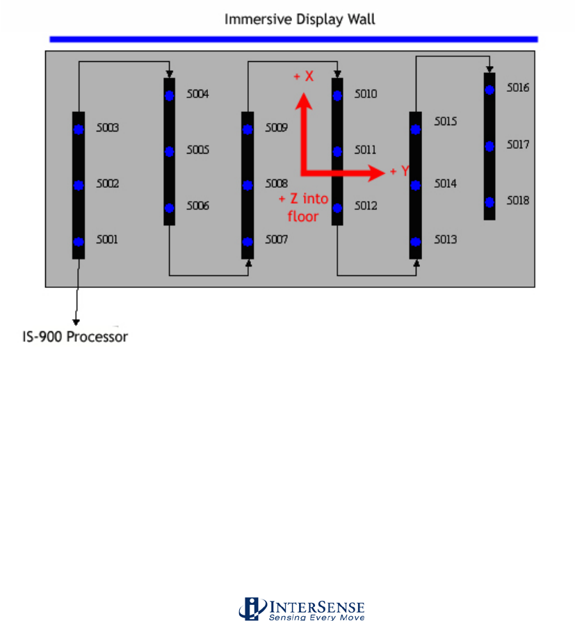
InterSense Doc. No. 072-00105-0I07 Rev. 4.2
IS-900 User Guide Page 41 of 177
3.3.1. SoniStrip Mounting for Ceiling Installations
The following is an example of an installation for a large area immersive room environment.
Important Note:
For customers upgrading existing MiniTrax systems to work with wireless MicroTrax devices – an
InterSense acoustic timing adjuster (ATA) must be inserted between the processor and the first
SoniStrip in the chain. The ATA allows users with revision 3 SoniStrips to use wireless MicroTrax
devices more effectively (improves tracking at close range).
Most applications for IS-900 systems are best realized with a ceiling mounting of several
SoniStrips in either a grid-like pattern or a staggered pattern as depicted in Figure 19 below. In
both cases, 6-foot SoniStrips are mounted to the ceiling using InterSense provided ceiling clips
that attach directly to most all suspended ceiling systems.
The SoniStrips are mounted approximately 2 to 3 feet apart, depending on the ceiling height. For
ceilings that are 8 feet high, mount SoniStrips with 2 foot separation. For lower ceilings, consider
using 4-foot SoniStrips mounted 2 feet apart. For ceiling mounts from 9 to 12 feet high, mount 6-
foot SoniStrips approximately 3 feet apart and plan on using external power boosters to maximize
the acoustic measurement range of the IS-900.
Figure 19 - Immersive Room Ceiling Mounting (top down view)
In Figure 19, the coordinate system is shown from a “top down view”, identical to the default
Constellation Array view used with the InterSense set up software ISDEMO. Each SoniStrip is
wired in sequence from the lower left hand corner of the SoniStrip Constellation Array connecting
to Port 5 on the IS-900 Processor.
Definition of the SoniStrip ID numbers come from the wiring sequence, or “daisy chain”, and IS-
900 Processor port number that is used to connect to the Constellation Array. Here, the SoniStrip
Array is plugged into Port 5 thus becoming a sequence with SoniDisc ID numbers from 5001 to
5018.
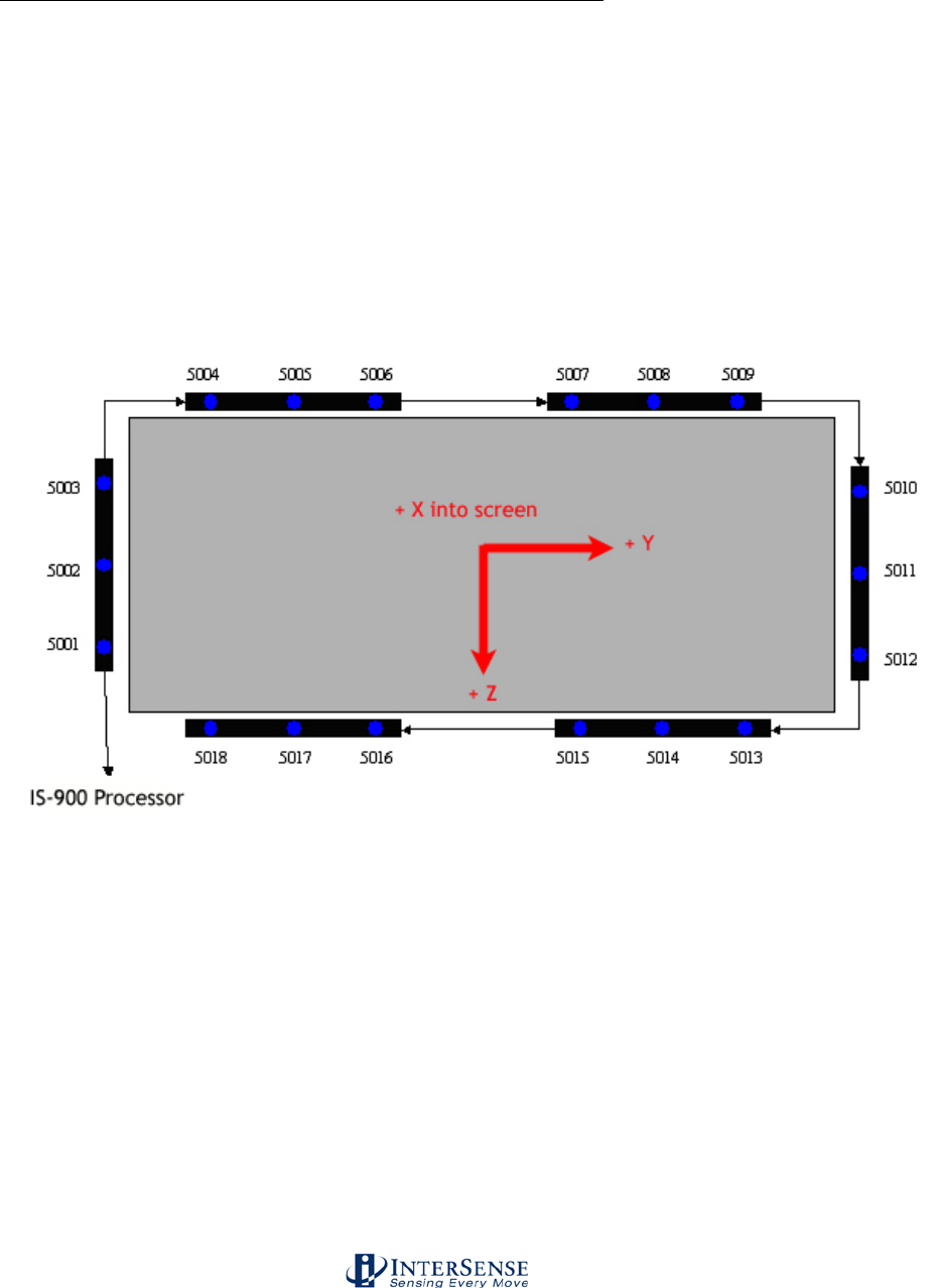
InterSense Doc. No. 072-00105-0I07 Rev. 4.2
IS-900 User Guide Page 42 of 177
With each SoniStrip mounted in the same orientation on the ceiling and pointing down, the normal
vectors then for the installation and wiring shown in Figure 19 become:
SoniDisc ID Nos. Normal Vectors used in Constellation Array
5001 – 5018 0.000, 0.000, 1.000
3.3.2. SoniStrip Mounting for Power Wall Installations
The following is an example of an installation for a typical power wall.
A typical immersive display wall consists of one or more stereo projectors that illuminate a flat (or
curved) screen. This type of display is ideal for mounting the IS-900 SoniStrips surrounding the
screen with each SoniStrip angled at 45 degrees towards the center of the screen. Figure 20
shows a typical, two-projector, flat display using six, 6-foot SoniStrips in a perimeter mount
configuration.
Figure 20 - Power Wall Perimeter mounting (front forward view)
Each SoniStrip is mounted along the edge of the display using the InterSense provided angle
brackets. The SoniStrips on the top and bottom of the display are spaced approximately 2 to 3
feet apart, depending on the size of the display wall. The InterSense coordinate system for
Figure 20 has X forward looking into the screen, Y positive to the right, and Z positive down in
the direction of gravity.
Each SoniStrip is wired in sequence with the bottom left corner connecting to Port 5 of the IS-900
Processor. The SoniStrip ID numbers are defined by the wiring and port number and become a
sequence with numbers from 5001 to 5018.
With each SoniStrip angled at 45 degrees toward the screen center, the normal vectors for the
installation and wiring shown in Figure 20 become:
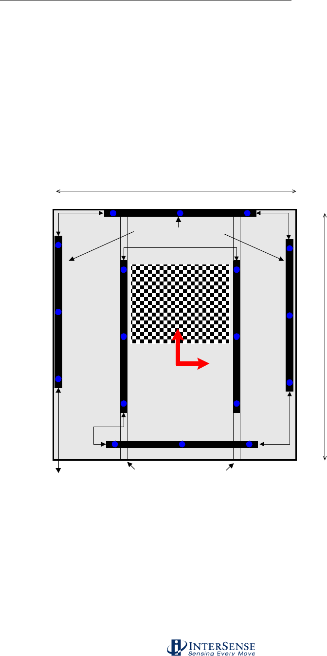
InterSense Doc. No. 072-00105-0I07 Rev. 4.2
IS-900 User Guide Page 43 of 177
SoniDisc ID Nos. Normal Vectors used in Constellation Array
5001 – 5003 -0.707, 0.707, 0.000
5004 – 5009 -0.707, 0.000, 0.707
5010 – 5012 -0.707, -0.707, 0.000
5013 – 5018 -0.707, 0.000, -0.707
3.3.3. SoniStrip Mounting for CAVE-like Installations
The following is an example of an installation for a typical CAVE-like environment.
The IS-900 excels over magnetic or optical trackers in CAVE-like installations. As shown in
Figure 21, the SoniStrips are positioned to provide uniform tracking coverage throughout the
entire immersive display environment with no distortion or occlusion issues.
3 meters
3 meters
Mirror
SoniStrips Mounted at
45 degree angles
Additional Mounting Support
IS-900 Processor
5001
5002
5003
5004 5005 5006
5009
5008
5007
5013
5014
5015
5018
5017
5016
5012 5011 5010
+ X
+ Y
+ Z
into floor
Figure 21 - CAVE-like Installation (top down view)
The example above is a 3 meter cube, 4 walled immersive display system which uses six 6-ft.
SoniStrips. Depending of the number of display walls, display volume and mirror position/size, it
may be necessary to use a variety of different sized SoniStrips (6, 4, and 2 foot) or SoniPods
discretely located to provide the optimum tracking coverage. Please consult with InterSense
regarding all CAVE-like installations to maximize the tracking performance.
The first three SoniStrips mounted along the top and around the perimeter of the CAVE walls, are
angled in towards the CAVE center at 45 degrees. The remaining three SoniStrips are mounted

InterSense Doc. No. 072-00105-0I07 Rev. 4.2
IS-900 User Guide Page 44 of 177
with the normal vectors pointing straight down on each side of the center ceiling mirror and along
the back side of the CAVE. The mounting of these three interior SoniStrips may require the
addition of two U-Channels, positioned front to back, on each side of the mirror at the top, center
of the CAVE.
Each SoniStrip is wired in sequence with the bottom left corner connecting to Port 5 of the IS-900
Processor. The SoniStrip ID numbers are defined by the wiring and port number and become a
sequence with numbers from 5001 to 5018.
With three perimeter SoniStrips angled at 45 degrees toward the CAVE center and the three
interior SoniStrips pointing straight down in the Z-axis, the normal vectors then for the installation
and wiring shown in Figure 24 become:
SoniDisc ID Nos. Normal Vectors used in Constellation Array
5001 – 5003 0.000, 0.707, 0.707
5004 – 5006 -0.707, 0.000, 0.707
5007 – 5009 0.000, -0.707, 0.707
5010 – 5018 0.000, 0.000, 1.000
3.3.4. SoniFrame and SoniWing
Please refer to the IS-900 Product Supplement Manual titled “IS-900 Fixed Frame Assemblies—
SoniFrame & SoniWing”, Doc. No. 072-00088-0G04, for details on the assembly and set up of
these pre-calibrated SoniDisc Constellation Arrays.
The InterSense installation and testing software, ISDEMO, has commands in the Constellation
Tool that allow rapid installation and calibration of the SoniWing and SoniFrame. This tool
automatically generates both the position and normal vectors for these fixed frame, factory
calibrated SoniDisc Constellation options. Refer to Section 10.7 for information about using
ISDEMO to install SoniWing and SoniFrame Constellation Arrays.
3.4. Measurement and Calibration of SoniStrips
Once the SoniStrip Constellation array is installed and wired, the next step is to accurately
measure the absolute positions of each SoniDisc in the array.
Two methods can be used to calibrate the installed SoniStrip beacon array:
1. Optical Surveying (sighting with a surveying tool, i.e. a Nikon total station). This is the most
precise method of calibration. Use this method for installations in all virtual environments.
2. Direct Measurement (hand measurement with a tape measure). This technique is not
recommended for most installations but can be used temporarily to quickly test an IS-900
installation when the first technique is not possible. ISDEMO has SoniStrip positioning and
alignment tools that help when performing a quick installation using the direct measurement
approach. Refer to Section 10.7 for details.
NOTE: In calibrating the SoniStrip constellation array, it is very important that the
measurements are as accurate as possible. Accurately measuring the SoniStrip beacon
constellation array will directly impact tracking performance. Use a Total Station (Nikon DTM 420
or equivalent), or other means to accurately measure the absolute position vector for each
SoniDisc. Contact InterSense for Total Station recommendations or installation support.

InterSense Doc. No. 072-00105-0I07 Rev. 4.2
IS-900 User Guide Page 45 of 177
When measuring the SoniStrip Constellation Array with a Total Station:
1. Read the manufacturer’s instructions on the set-up and operation of the surveying tool. Make
sure the measurement tool can report absolute X, Y, and Z coordinates for each
measurement. The IS-900 Tracking system needs the X, Y, and Z position measurement for
each SoniDisc location in order to properly track.
2. Measure the X, Y, Z coordinates of each SoniDisc and write down the measurements in a
table listing beacon position (x, y, z values in meters), normal vector (for ceiling applications
the normal vector nx, ny, nz is always 0.00,0.00,1.00). The SoniDisc ID number is determined
by the port the SoniStrip “daisy chain” is plugged in to (i.e. Port 5 for our examples is Section
3.3) and the sequence number in the daisy chain (i.e. the first SoniStrip in a daisy chain will
have SoniDisc IDs 5001, 5002 and 5003).
For example: 1.2000, 0.0000, 0.0000, 0.00, 0.00, 1.00, 5001
Sample sheet to enter X, Y, Z measurements of each beacon
X
Y
Z
Nx
Ny
Nz
Beacon #

InterSense Doc. No. 072-00105-0I07 Rev. 4.2
IS-900 User Guide Page 46 of 177
3. Using the InterSense command format:
MCF{beaconNum}, X, Y, Z, Nx, Ny, Nz, BeaconID
Where,
{beaconNum} is a sequential number (i.e. 1, 2, 3, …)
X, Y, Z are the beacon locations in meters in nav-space (X forward, Y to the right, Z down),
Nx, Ny, Nz are the pointing vectors of the beacon, usually they point down in the +Z direction so
entering 0,0,1, is correct; and,
BeaconID is the SoniDisc number determined by the “daisy chain” sequence of the SoniStrips for
that specific beacon (i.e. with SoniStrips plugged into port 5, the sequence starts at 5001, 5002,
5003, 5004, etc…).
Enter beacon locations in meters into comma delimited text file (.txt) using WordPad or any text
editing application on your PC in the following format shown in the example below. The “MCC”
line at the beginning is a command to clear the current constellation, and the “MCe” line at the
end is to apply the constellation.
Example of .txt file with X, Y, Z measurements
MCC
MCF1, 0.0000, 0.0000, -3.0000, 0.00, 0.00, 1.00, 5001
MCF2, 0.0000, 0.9144, -3.0000, 0.00, 0.00, 1.00, 5002
MCF3, 0.0000, 1.8288, -3.0000, 0.00, 0.00, 1.00, 5003
MCF4, 0.6000, -0.5050, -3.0000, 0.00, 0.00, 1.00, 5004
MCF5, 0.6000, 0.4094, -3.0000, 0.00, 0.00, 1.00, 5005
MCF6, 0.6000, 1.3238, -3.0000, 0.00, 0.00, 1.00, 5006
MCF7, 1.2000, 0.0000, -3.0000, 0.00, 0.00, 1.00, 5007
MCF8, 1.2000, 0.9144, -3.0000, 0.00, 0.00, 1.00, 5008
MCF9, 1.2000, 1.8288, -3.0000, 0.00, 0.00, 1.00, 5009
MCF10, 1.8000, -0.5030, -3.0000, 0.00, 0.00, 1.00, 5010
MCF11, 1.8000, 0.4114, -3.0000, 0.00, 0.00, 1.00, 5011
MCF12, 1.8000, 1.3258, -3.0000, 0.00, 0.00, 1.00, 5012
MCF13, 2.4000, 0.0030, -3.0000, 0.00, 0.00, 1.00, 5013
MCF14, 2.4000, 0.9174, -3.0000, 0.00, 0.00, 1.00, 5014
MCF15, 2.4000, 1.8318, -3.0000, 0.00, 0.00, 1.00, 5015
MCF16, 3.0000, -0.5030, -3.0000, 0.00, 0.00, 1.00, 5016
MCF17, 3.0000, 0.4114, -3.0000, 0.00, 0.00, 1.00, 5017
MCF18, 3.0000, 1.3258, -3.0000, 0.00, 0.00, 1.00, 5018
MCe

InterSense Doc. No. 072-00105-0I07 Rev. 4.2
IS-900 User Guide Page 47 of 177
3.5. Connections with IS-900 Processor
This section describes the final steps to setting up the IS-900 system.
1. Connect all the tracking devices and SoniStrip Constellation Array to the IS-900
Processor
Important! Always power down the IS-900 Processor and any external power boosters prior to
connecting or removing any cables. DO NOT “hot plug” any devices into the IS-900 Processor –
connecting devices to the IS-900 while the power is on will result in damage to both the IS-900
Processor and the tracking devices.
Wired MicroTrax Devices
For wired MicroTrax Devices, please see Figure 13. If you have a MicroTrax Head Tracker, it
connects directly to the Adapter: TTL to RS422, (item 4 in Figure 13). If you have a wand, it
connects directly to the Adapter:RS232 to RS422, (item 6 in Figure 13).
Next, connect the adapter(s) to the processor using the 30 ft. cable (part number 078-00088-
0030). Either adapter uses the same cable to the processor. You can use Ports 1, 2, 3, 4, 6, 7 or
8 on the VETracker for tracking devices or a second SoniStrip Constellation “daisy chain.”
However the SimTracker has only Ports 1, 2, 3 and 4 available for tracking devices or a second
SoniStrip Constellation “daisy chain.”
Next, connect the SoniStrip Constellation Array into Port 5 on the back of the IS-900 Processor
using the 30 ft. cable (part number 078-00088-0030).
Wireless MicroTrax Devices
For wireless MicroTrax devices, please see Figure 14. If you have a MicroTrax Head Tracker, it
connects directly to the MicroTrax Wireless Transmitter (item 7 in Figure 14). Whether you have
a Head Tracker, a Wand or both, each needs a Wireless Receiver. Simply connect the integrated
cable on the Wireless Receiver into the Processor.
Connect the SoniStrip Constellation Array into the Acoustic Timing Adapter (item 9/ATA in Figure
14). Then connect the ATA into Port 5 on the back of the IS-900 Processor. Similar to wired
devices, additional tracking devices or a second SoniStrip Constellation “daisy chain” can use
Ports 1, 2, 3, 4, 6, 7, or 8 on the VETracker. The SimTracker has only Ports 1, 2, 3 and 4
available for additional tracking devices or a second SoniStrip Constellation “daisy chain.”
Important Note: Each SoniStrip Constellation “daisy chain” needs one ATA. If you use
additional constellations, then you will need an additional ATA for each additional constellation.
When connecting the cables to the IS-900 system, please always follow these guidelines:
• Only use supplied cables to connect the SoniStrips to the IS-900 Processor. DO
NOT use standard phone cables or network cables, as they do not have the
correct pin-outs used with the IS-900 tracking system.
• If a need arises to build additional cables, use RJ48 flat cabling and RJ48
connectors. Call InterSense Technical Support for a detailed specification or with
any cabling questions (+1 781 541 7624).
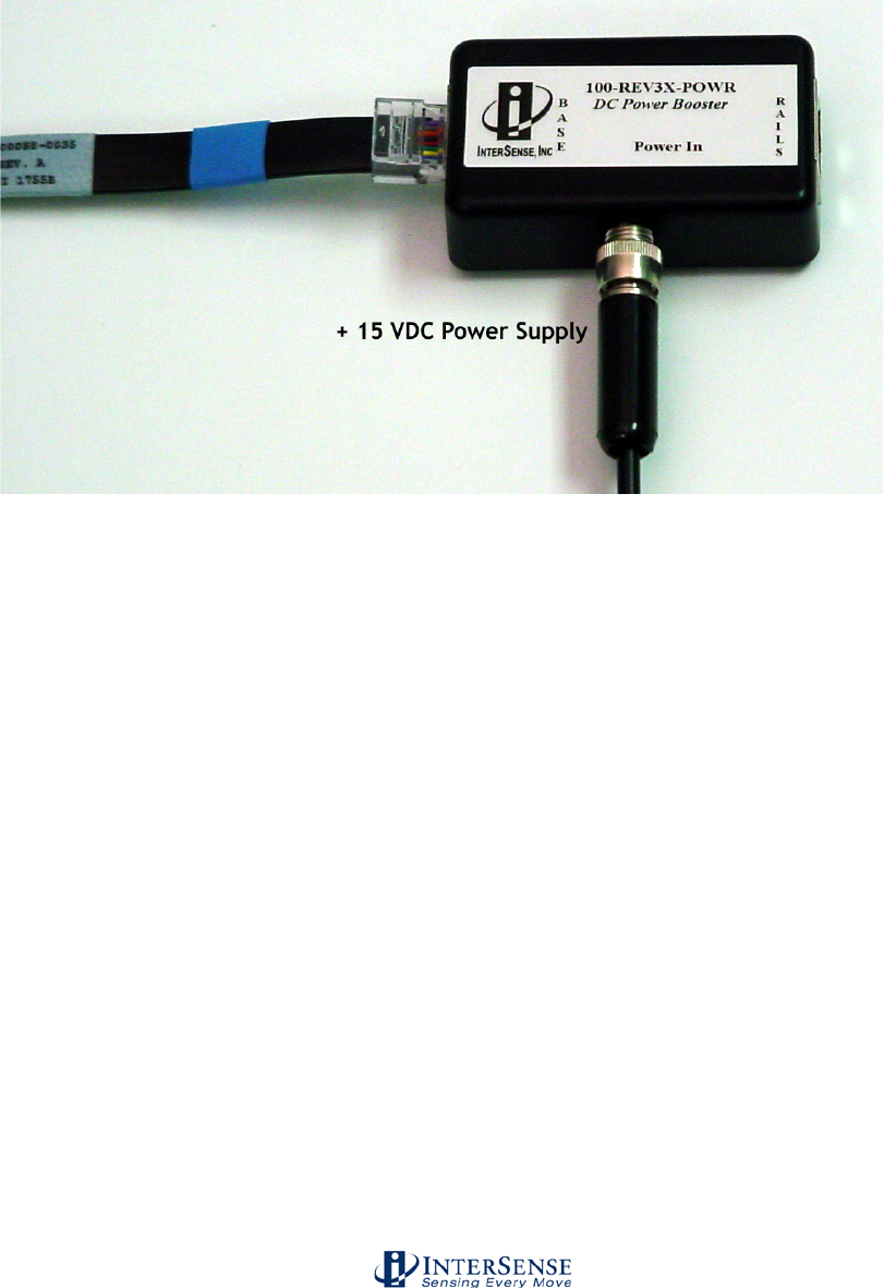
InterSense Doc. No. 072-00105-0I07 Rev. 4.2
IS-900 User Guide Page 48 of 177
A Power booster (Figure 22) must be connected in between Port 5 and the end of the SoniStrip
“daisy chain” and of the IS-900 Processor to supply the additional power to the SoniDiscs for:
• Measurement ranges greater than 3 meters or,
• SoniStrip Arrays configured with more than 12 SoniStrips, where an additional power
booster is required after every 12th SoniStrip in a large SoniStrip Constellation Array.
Figure 22 - External Power Booster for SoniStrips
2. Setup your PC and launch ISDEMO
Follow the directions in Section 10 to install and run ISDEMO on a PC.
3. Connect the communications to the IS-900 system
Choose a communication option for connecting to the PC running ISDEMO. Section 10.3 details
the communication options for connecting with either serial or Ethernet.
3.6. Wireless MicroTrax Setup
Skip this step if you are using wired tracking devices.
3.6.1. Wireless Device Types
InterSense manufactures Base Receiver Module and trackers in two bands, 2.4 GHz and
900 MHz. These may be used together on the same system if desired. Channel numbering
is from 0 to 15 for 2.4 GHz devices and from 1 to 10 for 900 MHz devices; since the
receivers operate in different bands, the same channel number may be used in each band
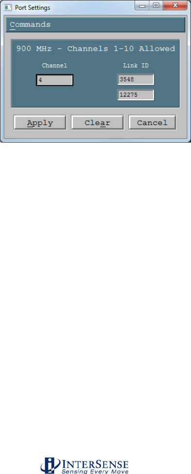
InterSense Doc. No. 072-00105-0I07 Rev. 4.2
IS-900 User Guide Page 49 of 177
simultaneously, for example it is acceptable to set a 900 MHz and 2.4 GHz tracker/Base
Receiver Module to channel 4 on the same system.
900 MHz wireless devices allow receiver sharing, which is a special mode that allows two
trackers to connect to a single Base Receiver Module.
3.6.2. Receiver Sharing (900 MHz)
When receiver sharing is configured by adding a second link ID to the port configuration as
shown below, two important changes occur.
The first change is that all physical ports on the IS-900 are mapped to 2 stations, so trackers
communicating with the receiver on processor port 1 become stations 1 and 2, trackers on
port 2 become stations 3 and 4, etc. This only applies to trackers and Base Receiver
Modules, not SoniStrips, which are still numbered based on the physical port number.
Wired devices and 2.4 GHz wireless devices (which do not support channel sharing) are
assigned to the first station on a given port (2*p-1, where p is the port number), for example
a wired tracker in port 4 would become station 7. Physical ports above port 4 cannot be
used for trackers/Base Receiver Modules in this configuration.
The second change that occurs when using receiver sharing is a decrease in update rate of all wired
and wireless devices, from approximately 120 Hz to 110 Hz.
3.6.3. Wireless Device Configuration
IMPORTANT NOTE: Additional wireless IS-900 tracking systems in the immediate area
should be shut down while a new system is being configured to avoid the possibility of
interference during setup.

InterSense Doc. No. 072-00105-0I07 Rev. 4.2
IS-900 User Guide Page 50 of 177
Please refer to the RFScope tool (Section 10.8) to assist in choosing an optimal RF channel
for MicroTrax devices.
If you are using wireless devices, we recommend fully charging the Radio/Battery Modules
prior to use. If the power LED on the wireless Wand or Head tracker transmitter is flashing,
that is an indication of a low battery. Once the wireless receiver / transmitter combinations
have been configured below, each receiver will be matched to exactly one transmitter via
an “RF Channel” and “Link ID”. The system will not need to be configured again unless the
user wishes to change the receiver/transmitter pairing.
1. Make sure the IS-900 Processor is powered off.
2. Plug the Base Receiver Modules into the IS-900 Processor.
Plug the cable coming from the Base Receiver Modules directly into one of the
IS-900 Processor Ports (Ports 1 to 5 on the SimTracker processor or Ports 1 to
8 on the VETracker processor) on the rear of the processor.
3. Turn on the wireless tracking devices by holding the power buttons for approximately 2
seconds.
4. On the wireless wand, the power button is the button farthest to the left (under the joystick).
On the wireless head tracker, the power button is the only button available on the transmitter
pack that connects to the tracker itself.
5. Turn on the IS-900 processor. When the system has finished booting, verify that each
receiver has a green power LED lit. (If there are no LEDs on any of the receivers, then they are
not receiving power and they will not be configurable. Power off the IS-900 processor and check
that the cable was inserted securely).
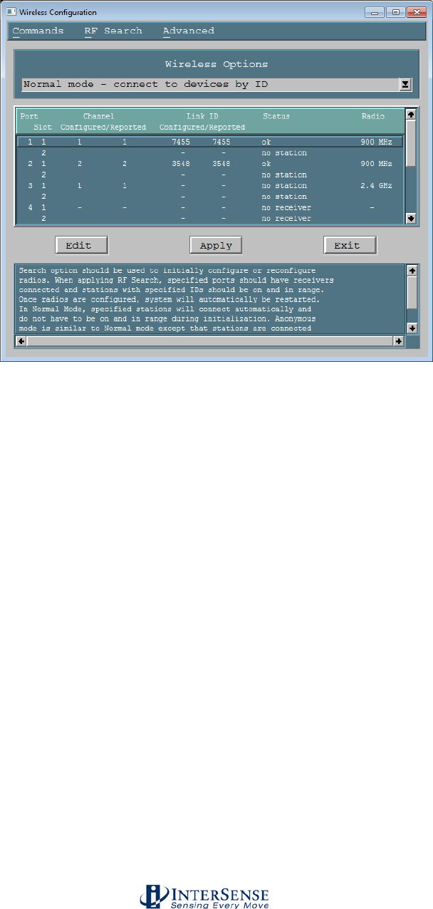
InterSense Doc. No. 072-00105-0I07 Rev. 4.2
IS-900 User Guide Page 51 of 177
6. Run ISDEMO and connect to the processor via the “IS-900” configuration. Click
“Parameters->Wireless Configuration” from the menu. You will be presented with the following
dialog; set the Mode dropdown box to “Normal mode – connect to devices by ID”:
Normal Mode Determines wireless communication by device Link IDs
Anonymous Mode Determines wireless communication by wireless channel, and ignores
Link IDs
Port Port of the IS-900 Processor.
Configured Channel The channel that the connected Base Receiver Module is configured to.
No two Base Receiver Modules can be configured to the same channel /
band pair (however, the same channel is permitted if using a 900 MHz
and 2.4 GHz receiver, since each channel represents a different
frequency).
Reported Channel The channel that the connected Base Receiver Module is currently
configured for (0-15 for 2.4 GHz, 1-10 for 900 MHz).
Configured Link ID The link ID that is assigned to the receiver. Each wireless tracker has a
link ID associated with it when it is shipped, based on the lower 5 digits
of the internal device serial number. This 4-5 digit number can be found
on a label on your tracker (or its cable for trackers with cables).
Reported Link ID The link ID that is currently associated to the Base Receiver Module.
Status Port status. Any ports with a status of “no receiver” did not have a Base
Receiver Module detected, and cannot be configured.
Radio 900 MHz or 2.4 GHz band; both may be used simultaneously.
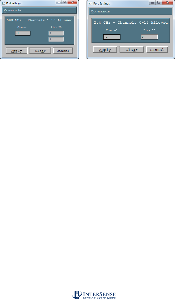
InterSense Doc. No. 072-00105-0I07 Rev. 4.2
IS-900 User Guide Page 52 of 177
7. Click a row that corresponds with a receiver and click the “Edit” button. A dialog similar to
the following will be presented (900 MHz and 2.4 GHz radio dialogs shown):
8. Enter a channel into the first input box. The valid range of channels is 0-15 for 2.4 GHz and
1-10 for 900 MHz. No two Base Receiver Modules can use the same channel on the same band.
For best results, it is recommended that channels be configured such that they are separated by
one unused channel if possible, though it is better to have channels adjacent than to have a
device set to a channel with a high level of RF interference. Use of the RFScope utility is
recommended when initially choosing channels. If multiple IS-900 systems are in use in the
same general area (within a few hundred feet), the Base Receiver Module and Trackers should
be set to different channels to minimize interference.
9. The Base Receiver Module will now be linked to a specific tracker via the “Link ID” input box.
Enter the Link ID of an appropriate device and click “Apply”. If the second Link ID input box is
used for a 900 MHz Base Receiver Module, Receiver Sharing mode will be activated. The
wireless configuration dialog should now appear similar to this:
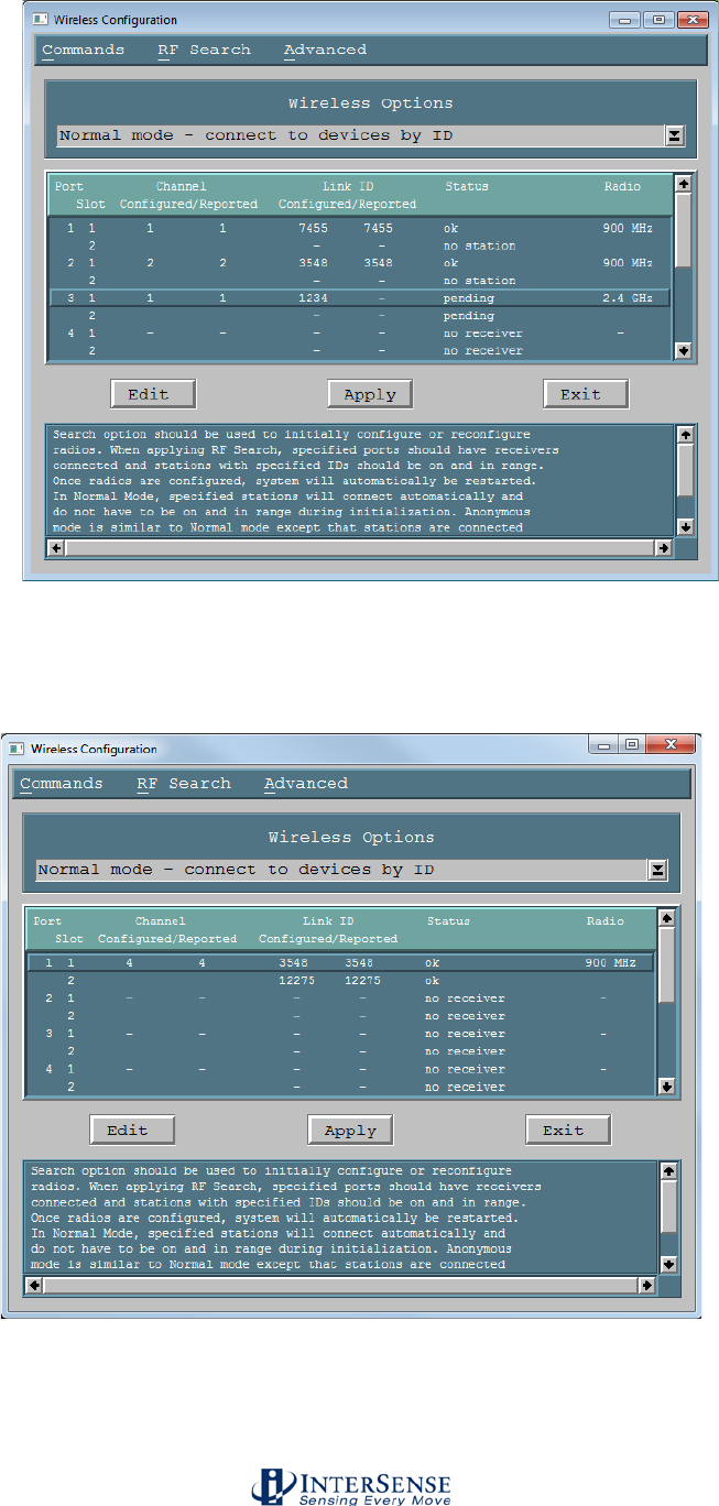
InterSense Doc. No. 072-00105-0I07 Rev. 4.2
IS-900 User Guide Page 53 of 177
If 900 MHz channel-sharing functionality is used (multiple devices per receiver), the dialog will
indicate multiple slots per port, and each port/slot will be considered a “station”, so port 2 slot 1
would be mapped to station 3 in ISDEMO and the InterSense API, for example:
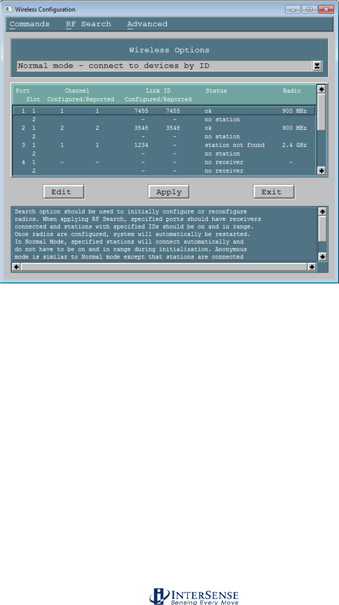
InterSense Doc. No. 072-00105-0I07 Rev. 4.2
IS-900 User Guide Page 54 of 177
10. Make sure that all configured Trackers are powered on and click the “Apply” button.
ISDEMO will prompt you if an RF Search is recommended. It may take a minute or two for the
processor to apply the configuration. If the devices are communicating properly, both green
LEDs should now be lit on both the Trackers and Base Receiver Modules. The status should
also be listed as “ok”. If the status is “station not found” click Search→RF Search.
Helpful Tip: Placement of Wireless Base Receiver Module
You should not place the Base Receiver Module inside a metal container. If the IS-900 is rack-
mounted, we recommend placing the adapters outside of the rack mount. In ideal conditions, the
Base Receiver Module can be as far away as 100 feet from the Transmitter Module. But if you
are having an interference issue, you may want to move the Base Receiver Module closer to the
tracking area to try to improve communication Extension cables are available to extend the
distance from the Base Receiver Module to the IS-900 Processor. You should keep the Base
Receiver Modules at least 10 cm (4 inches) apart from each other.
3.6.4. Checking the installation
Make sure you have followed the steps in the Software and Hardware Setup sections.
Turn off the IS-900 Processor.
Turn on the Wireless Transmitter or Wireless Wand.
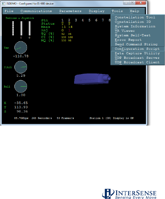
InterSense Doc. No. 072-00105-0I07 Rev. 4.2
IS-900 User Guide Page 55 of 177
The “Power” LED on the transmitter should be on. The “Link” LED on the transmitter should
be off. If the power LED is flashing or doesn’t turn on, the battery is low and you should
charge it before you continue or replace the battery with a charged one.
Note: If you turn the Wireless Transmitter Module ON but do not move it for more than 10 minutes
it will go into sleep mode and you will have to switch the power ON again.
Turn on the power to the IS-900 processor. The LEDs on the front panel next to each port should
come on and then stay on for each occupied port. The “Power” LED on the Wireless Receiver
should turn on. The Wireless Receiver ”Link” LED should turn on along with the Wireless
Transmitter “Link” LED.
If any of these steps failed or if the LCD on the front panel of the IS-900 processor indicates X for
the wireless station, refer to the Troubleshooting section in this manual.
Place the tracking device(s) under the IS-900 SoniStrip Constellation. The LCD on the front
panel of the IS-900 Processor should show a ‘T’ for each station indicating it is tracking. If it
shows an ‘L’ (lost), then you need to confirm that the tracking device is within the tracking volume
and the SoniStrip Constellation has been properly configured in the IS-900 Processor using
ISDEMO. If you are unable to get the tracker to work properly please contact Technical Support
using the information in the Contact section of this manual.
3.6.5. Loading the Constellation File
Open the Configuration Script window in ISDEMO
Under the Tools menu in ISDEMO, click on Configuration Script (Figure 23) to open the
Configuration Script window.
Figure 23 - Configuration Script Menu for loading SoniStrip Constellation array file
From the Configuration Script window under File menu, select Load from File (Figure 24).
Locate the SoniStrip Constellation Array .txt file created in Step 3.4 above. Double click on the
file and click on OK.
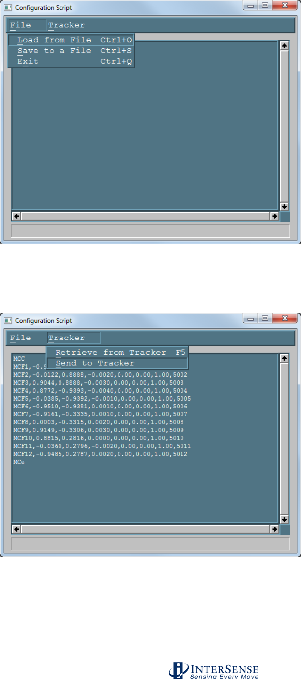
InterSense Doc. No. 072-00105-0I07 Rev. 4.2
IS-900 User Guide Page 56 of 177
Figure 24 - Configuration Script File Menu
From the Configuration Script window under Tracker menu, select Send to Tracker (Figure 25).
The SoniStrip Constellation Array is now uploaded into the IS-900 Processor.
Figure 25 - Sending Configuration Script to Tracker
Check the Configuration
To check the configuration, open the Constellation Configuration Tool window by selecting
Tools→ Constellation Tool from the Tools menu in the main window of ISDEMO (Figure 26).
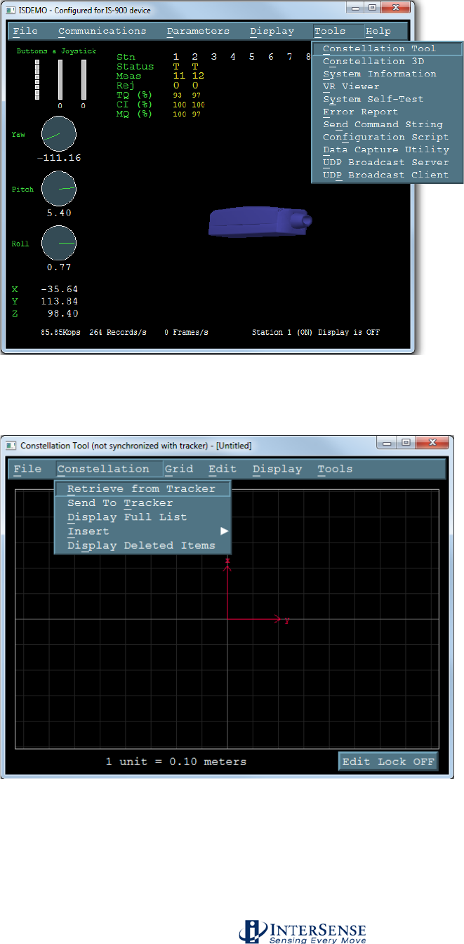
InterSense Doc. No. 072-00105-0I07 Rev. 4.2
IS-900 User Guide Page 57 of 177
Figure 26 - Constellation Tool Selection
From the Constellation Configuration Tool window, select Retrieve from Tracker from the
menu item Constellation (Figure 27).
Figure 27 - Checking installed SoniStrip Constellation Array
This will upload the grid into the Constellation Configuration Tool window from the IS-900
Processor. At this point, you should see SoniStrip Constellation Arrays similar to examples
covered in Section 3.3 for typical configurations (Figure 28, Figure 29 - ISDEMO Constellation
Tool Screen for Wall Mount Power Wall Applications and Figure 30).
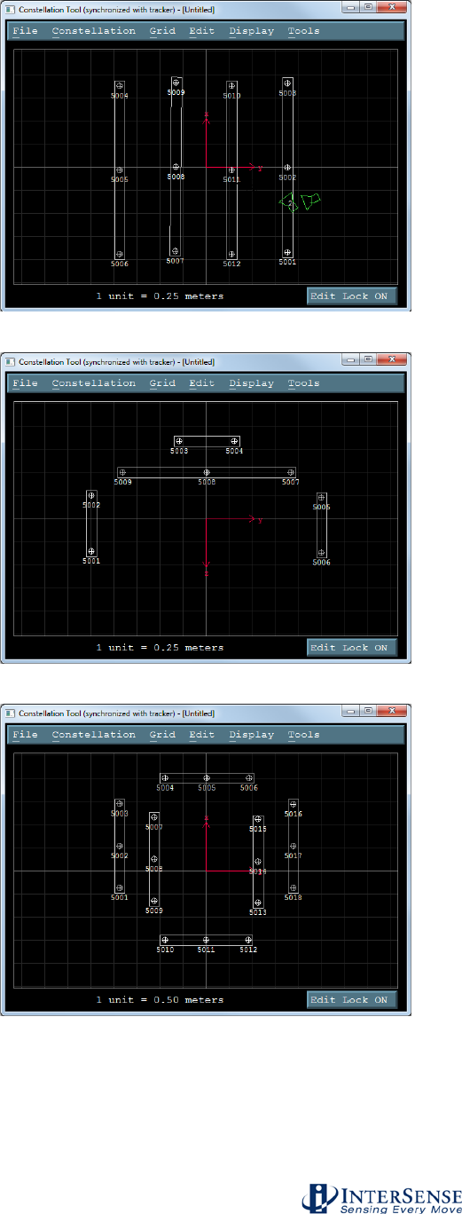
InterSense Doc. No. 072-00105-0I07 Rev. 4.2
IS-900 User Guide Page 58 of 177
Figure 28 - ISDEMO Constellation Tool Screen for Ceiling Mount Power Wall Applications
Figure 29 - ISDEMO Constellation Tool Screen for Wall Mount Power Wall Applications
Figure 30 - ISDEMO Constellation Tool Screen for CAVE-like Applications
Verify system is tracking
While still in the Constellation Configuration Tool window, type CTRL-D (or select menu item
Display→Start Displaying Data as shown in Figure 31) to verify the Constellation Array is
correctly installed and the system is tracking. The tracked device will appear green in the center
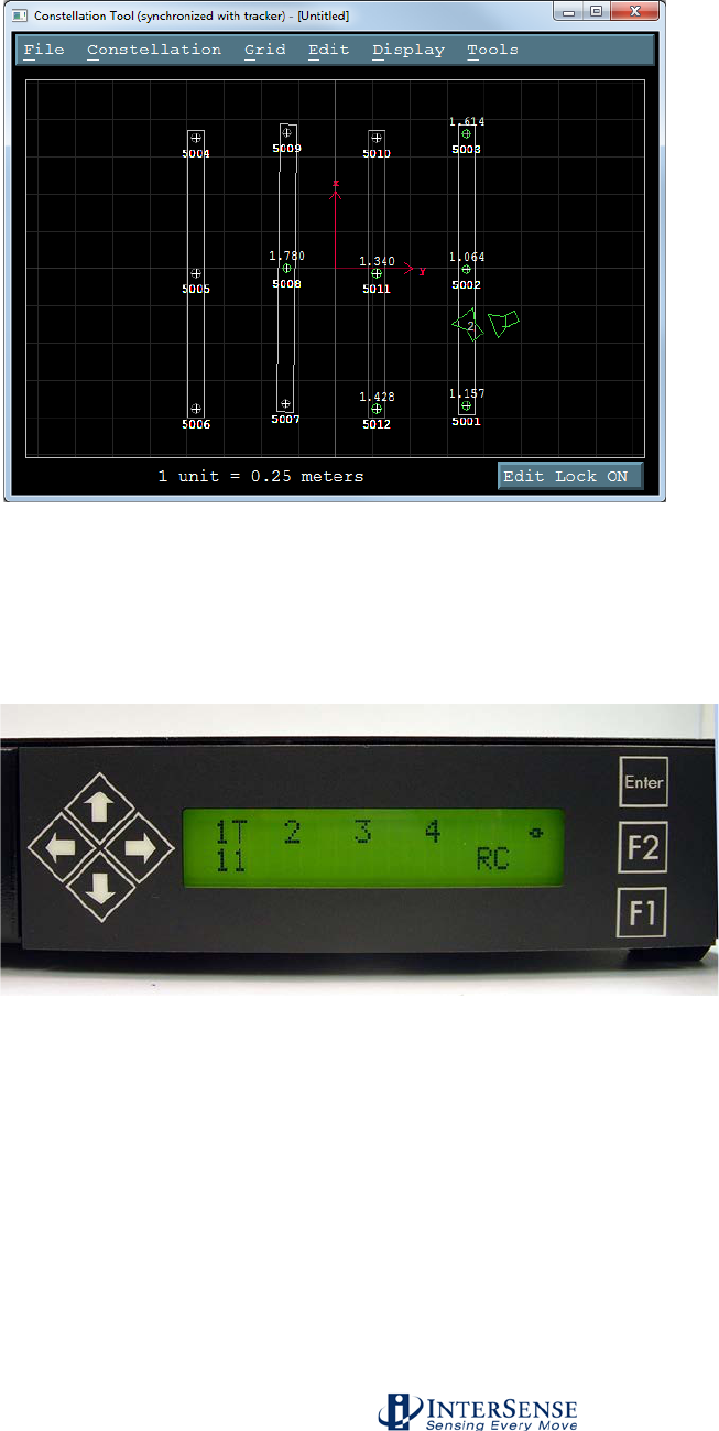
InterSense Doc. No. 072-00105-0I07 Rev. 4.2
IS-900 User Guide Page 59 of 177
of the display window indicating correct tracking. Move the physical tracker around and see it
move in the display window.
Figure 31 - ISDEMO Constellation Tool Screen with Tracking Devices
Also check the LCD panel of the IS-900 Processor. For each connected tracking station, “T”
should appear on the IS-900 Processor’s front LCD panel to indicate proper tracking (Figure 32).
If an “X”, appears it may indicate hardware, cabling or wireless link issues. Go back to Steps 5 &
6 to reload the proper configuration script containing the correct Constellation Configuration
Array. Refer to Section 7 for troubleshooting hardware, cabling and wireless connectivity issues.
Figure 32 - Tracking Status Display on IS-900 LCD Panel
Saving the Configuration
Save the current settings into firmware of the IS-900 Processor by selecting the menu item File→
Save Current Settings from the main ISDEMO (Figure 33). A window will come up asking to
save into permanent memory. Select YES to save into permanent memory.
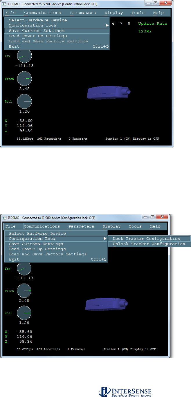
InterSense Doc. No. 072-00105-0I07 Rev. 4.2
IS-900 User Guide Page 60 of 177
Figure 33 - Saving All Configuration Settings to IS-900 Processor
Locking the configuration
Locking the settings will prevent inadvertently changing settings when not desired. Lock the
settings by selecting menu item File→Configuration Lock in main ISDEMO window (Figure 34).
A window will come up asking to Lock tracker configuration. Click on Lock Tracker Configuration.
Figure 34 - Locking Configuration Settings in IS-900 Processor

InterSense Doc. No. 072-00105-0I07 Rev. 4.2
IS-900 User Guide Page 61 of 177
Connecting to application
Follow the instructions or manual that came with the tracked application for using the IS-900
tracking system. If you have problems connecting to your application, first contact the application
developer for detailed information about connecting to InterSense tracking systems. If you still
need assistance, contact InterSense for technical support.
The IS-900 CD delivered with this system contains InterSense Software Development Kit (SDK)
for developing interfaces specific to new applications. The application programmers interface
(API) and library calls to the InterSense libraries are documented in Section 12.
3.6.6. Using Wireless MicroTrax Devices
When power is powered on, the Transmitter Module “Power” LED will turn on. When the battery
voltage gets to a low level, the Transmitter Module “Power” LED will begin to flash. This indicates
the devices should have about an hour of tracking left before the charger must be plugged in for it
to work.
If the MicroTrax Transmitter establishes communication with the Receiver, then the “In Range”
LED on the Transmitter will light and remain on as long as the device is in range or not in sleep
mode.
Sleep Mode: If no motion is detected by the Transmitter for about 10 minutes, it and the
MicroTrax will power down and the LEDs will turn off. Once the transmitter has shut itself off, it
must be manually powered on again before it can be used.
NOTE: While the Wireless Transmitter Module is turned off or out of range, the IS-900 Processor
will show an X in the LCD and the IS-900 trackers’ output of position and orientation will remain
fixed at their last value.
Summary of LEDs on Wireless Transmitter Module
Power: ON – The MicroTrax device and wireless Transmitter have power.
OFF – If the Power Switch is on may mean the battery is too low to operate the device.
FLASHING – The battery is low.
Connection Status:
OFF – If the Power LED is on, no connection has been made to a Wireless Receiver.
ON – The Transmitter is connected to a Wireless Receive.
FLASHING – Device is losing communication.
Summary of LEDs on Wireless Receiver Module
Power: ON – Wireless Receiver Module has power from IS-900 Processor
OFF – IS-900 is off or is not supplying power to this port.
Connection Status:

InterSense Doc. No. 072-00105-0I07 Rev. 4.2
IS-900 User Guide Page 62 of 177
ON – The Receiver is communicating (or attempting to communicate) with a Wireless
Transmitter Module.
OFF – A connection has not been established with a Wireless Transmitter Module.
Charging Instructions
Only use the power supply from InterSense when charging the Radio/Battery
board. Other chargers could cause failures and void the warranty. See the
battery handling instructions at the beginning of this manual.
When the “Low Power” LED on the Transmitter Module is ON or when you want to make sure
that the module is fully charged, you should connect the Transmitter Module to the charger. You
may leave the Transmitter Module on while charging; but, if you plan on using another
Transmitter Module– Base Receiver Module pair with the same channel selected, you must turn
off the Wireless Transmitter Module while it is being charged.
While it is charging, the LED next to the charger port will be on (Orange). When it turns solid
Green, the battery is finished charging (flashing green indicates that the battery is being “topped
off”). A fully discharged battery takes less than 4 hours to charge.
Changing a MicroTrax head tracking device from a wireless to wired configuration
To convert the MicroTrax devices from wireless to wired mode, follow these steps:
Turn off the IS-900 processor
Disconnect the appropriate receiver cable from the IS-900 Processor to the Base Receiver
Module.
Turn off the power on the Wireless Transmitter Module connected to the MicroTrax device.
Unplug the MicroTrax device from the Transmitter Module and plug it into the MicroTrax IS-900
Wired Adapter device.
Connect the wired adapter in the IS-900 Processor and turn the power on. No software or
configuration will need to be changed.

InterSense Doc. No. 072-00105-0I07 Rev. 4.2
IS-900 User Guide Page 63 of 177
4. Interface Communication Protocol
For firmware version 4.20 or higher
Terminology
Throughout this section and the ISDEMO program described in Section 10, certain terms and
acronyms are used to reference functional components of all InterSense tracking systems.
Specifically, IS-900 models contain an ultrasonic subsystem that includes SoniDiscs (Ultrasonic
Transponder Beacons) and Microphones (Ultrasonic Receiver Modules – URMs). To generalize
the interface protocol and configuration tools for these tracker models, InterSense uses the term:
PSE - Position Sensing Element.
A PSE may be Mobile or Fixed. Mobile PSEs are assigned to the stations and their movements
are tracked by the system (i.e. MicroTrax Microphones). Fixed PSEs form a CONSTELLATION
that is used as a reference for tracking (i.e. SoniStrips & SoniDiscs). In the case of IS-900
tracking systems, Microphones are mobile and SoniDiscs are fixed.
4.1. Commands Sent from the Host to the Tracker
<> Carriage return line feed pair- not needed for single character commands.
CR – ASCII value 13, LF – ASCII value 10.
{} List of parameters required for command.
[] List of optional parameters for command. Omitting those results in a query.
The IS-900 emulates most (but not all) of the commands in the Polhemus Fastrak™ protocol,
thus it is possible to use the IS-900 with most applications without writing new driver code. There
are also several additional commands added to access some of the advanced features of the IS-
900 that do not have any counterpart in the Fastrak™ protocol.
Note:
Firmware version 3.xx extended Fastrak™ protocol to support up to 32 stations (actual number
allowed is determined by your hardware configuration). StationNum in commands, status and
data records is now encoded in an extended hexadecimal notation. Numbers 1 to F conform to
standard hexadecimal notation, with numbers greater that F represented by additional upper case
letters of the alphabet. For example, number 16 is displayed as G.
4.2. Standard Fastrak™ Interface Commands
Data Record Request P Request a data record from all active stations.
Only used in polled mode.
Output mode C Put in continuous output mode.
c Put in polled output mode.
Default Polled mode

InterSense Doc. No. 072-00105-0I07 Rev. 4.2
IS-900 User Guide Page 64 of 177
Alignment Reference Frame
A{stationNum},[Ox,Oy,Oz,Xx,Xy,Xz,Yx,Yy,Yz]<>
Sets the coordinate frame with respect to which outputs for
that station will be reported. The coordinate frame is
defined by a set of three points. Ox,Oy,Oz defines the
origin of the new coordinate system, Xx,Xy,Xz defines a
point on the positive x-axis and Yx,Yy,Yz defines a point
on the positive y-axis. The points on the positive X and
positive Y axis are in the new coordinate frame rather than
the original coordinate frame. Values are not
cumulative/incremental, so any future changes are relative
to the original coordinate system.
For example, in order to configure station 1 to use a new
origin of (50, 60, 70)cm with the coordinate frame rotated
90 degrees about the +Z axis, the command would be
A1,50,60,70,50,61,70,49,60,70 (adding +1cm to the Xy
value and -1cm to the Yx value). Any length of vector
along +X and +Y may be used, as these are normalized
internally to a length of 2m (200cm), although for simplicity
we recommend adding the same value; in the example,
however, the command A1,50,60,70,50,400,70,12,60,70
(adding +340cm to Xy and -38cm to Yx) would cause the
same translation/rotation of the coordinate system. If
optional parameters are omitted, current values are
returned. Units are centimeters.
Default Fusion Mode: X=North, Y=East, Z=Down,
position origin is defined by
SoniStrip Constellation Array
horizontally leveled. See
Section 3.1.
Reset Alignment Reference Frame
R{stationNum}<>
Resets reference frame to the default.
Boresight Reference Angles
G{stationNum},[yawref, pitchref, rollref]<>
Sets the boresight reference angles for the specified
station. If set, these values are then used by the next
Boresight command instead of current orientation. If
optional parameters are omitted, current reference angles
are returned. Units are degrees.
Default 0,0,0

InterSense Doc. No. 072-00105-0I07 Rev. 4.2
IS-900 User Guide Page 65 of 177
Boresight Compatibility Mode
MBF<> Switch system to Fastrak Compatible mode.
MBI<> Switch system to Firmware Version 2.x Compatible
mode.
In firmware versions prior to 3.00 the B{stationNum}<>
command was implemented as the Heading Boresight (see
below) and full boresight was not available. To maintain
compatibility with the user software written at that time, two
Boresight Compatibility modes are available. In Fastrak
Compatible mode B{stationNum}<> command executes full
3-DOF boresight and MB{stationNum}<> effects heading
only. In the Firmware Version 2.x Compatible mode the
meanings of these commands are reversed.
Default Firmware Version 2.x Compatible, MBI<>
Boresight B{stationNum}<> (Fastrak compatibility mode)
MB{stationNum}<> (Firmware Version 2.x compatibility
mode)
Boresight a station. If boresight reference angles have
been specified by the G{stationNum}[yawref, pitchref,
rollref]<> command prior to issuing of Boresight command
then that orientation becomes the new reference point.
The angles output by the tracker at that orientation
become zero. Otherwise, system uses current station
orientation and that becomes the new reference line of
sight. Please make sure that the object being tracked (like
an HMD) is leveled and is pointing down the x-axis when
boresighting a station.
Unboresight b{stationNum} <> (Fastrak compatibility mode)
Mb{stationNum}<> (Firmware Version 2.x compatibility
mode)
Unboresight a station. Reference angles are cleared for
the specified station.
Heading Boresight B{stationNum}<> (Firmware Version 2.x compatibility
mode)
MB{stationNum}<> (Fastrak compatibility mode)
This command has no effect with the IS-900.

InterSense Doc. No. 072-00105-0I07 Rev. 4.2
IS-900 User Guide Page 66 of 177
Heading Unboresight b{stationNum}<> (Firmware Version 2.x compatibility
mode)
Mb{stationNum}<> (Fastrak compatibility mode)
This command has no effect with the IS-900.
Set Serial Communication Parameters
o{rate,parity,bits,HHS}<> Change the serial
communication parameters
rate is one of 3,12,24,48,96,192,384,576,1152
(rate is multiplied by 100)
parity N = none
O = odd
E = even
bits 7 or 8
HHS (Hardware handshake)
0 = OFF
1 = ON
Default serial communications settings:
rate 1152
parity N
bits 8
HHS OFF
System Record Request S Request a system status record to be sent.
Station Status l{stationNum},[state]<> Set the stationNum on or off.
state 0 = OFF, 1 = ON
Default All connected stations are on
Output Units Control U Sets output data record position units to inches.
u Sets the position units to centimeters. These only
matter in 6-DOF mode.
Default U
System control ^K Save the current settings to nonvolatile memory.
W Restore the system settings to the factory
defaults.
^Y Restart the firmware to the power up condition.
^S Suspend data transmission.
^Q Resume data transmission.
Caution: Sending W command will cause all the user
configuration information to be lost.

InterSense Doc. No. 072-00105-0I07 Rev. 4.2
IS-900 User Guide Page 67 of 177
Output record mode F Put in ASCII output mode
f Put in Binary output mode.
Default F
Output record list settings O{stationNum},[p1],[p2],[p3],.....,[pn]<>
Sets the output data list for stationNum. If optional
parameters are omitted, a data record containing current
output list settings for the station is returned.
Item
Description
Output Format
0
ASCII space character
1 ASCII byte
1
ASCII CR, LF pair
2 ASCII bytes
2
x, y, z position coordinates
3 floats
4
yaw, pitch, roll Euler angles
3 floats
5
X-axis direction cosines
3 floats
6
Y-axis direction cosines
3 floats
7
Z-axis direction cosines
3 floats
11
orientation quaternion
4 floats
16
stylus switch status (always 0)
1 byte (ASCII/binary)
18
x, y, z in 16 bit binary format
see below
19
yaw, pitch and roll in 16 bit
binary format
see below
20
quaternion in 16 bit binary
format
see below
21
time stamp, in selected time
units
see section 5.3.1
22
buttons
see below
23
joystick
see below
40
tracking status
0-255
68 – 71
auxiliary inputs
75
communication integrity
0-100
76
Measurement quality
0-100
Default 2,4,1
Data Item 4 – Euler Angles.
The Euler angles are defined as rotations about Z, then Y,
then X in body frame. Angles are returned in degrees
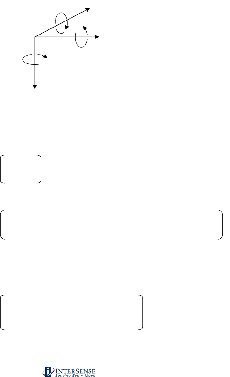
InterSense Doc. No. 072-00105-0I07 Rev. 4.2
IS-900 User Guide Page 68 of 177
Data Items 5, 6, 7 – Direction Cosines.
X-axis, Y-axis and Z-axis direction cosines can be used to
construct a 3x3 rotation matrix.
X direction cosines.
Y direction cosines.
Z direction cosines.
This matrix can also be constructed from Euler angles:
Data Item 11 – Orientation Quaternion.
Quaternion is returned as q = [w, x, y, z]. Quaternion to
rotation matrix conversion can be accomplished using the
following formula:
x1 x2 x3
y1 y2 y3
z1 z2 z3
1–2y2 – 2z2 2xy – 2wz 2xz + 2wy
2xy + 2wz 1 – 2x2 – 2z2 2yz – 2wx
2xz – 2wy 2yz + 2wx 1 – 2x2 –
2y2
cos(P)*cos(Y) sin(R)*sin(P)*cos(Y) - cos(R)*sin(Y) cos(R)*sin(P)*cos(Y) + sin(R)*sin(Y)
cos(P)*sin(Y) sin(R)*sin(P)*sin(Y) + cos(R)*cos(Y) cos(R)*sin(P)*sin(Y) - sin(R)*cos(Y)
-sin(P) cos(P)*sin(R) cos(P)*cos(R)
Yaw
Roll
Pitch
X
Y
Z

InterSense Doc. No. 072-00105-0I07 Rev. 4.2
IS-900 User Guide Page 69 of 177
Data Items 18, 19, 20 – 16 bit binary format.
16 bit binary format can be used in applications requiring
fastest possible serial I/O. Each floating point number is
stored in 2 bytes with only 14 bits containing actual data.
This results in lower accuracy than the standard IEEE
floating point format.
Data is 2’s-complement. The first byte of the data set has
its high-order bit set to 1; all others have them set to zero.
This can be used for data synchronization. Data is
returned low-order byte, then high-order byte. Use
following code sample as an example on how to decode
this format:
To decode position:
lo = (dataRecord[3] & 0x007F);
hi = (dataRecord[4] & 0x007F);
int14bit = (lo « 2) | (hi « 9);
result = (float) int14bit * 3.0 / 32768.0;
Result is a number representing position (in meters) and has a
full range of ± 3.0 meters (−300.0 to+299.963 centimeters or –
118.110 to 118.096 inches).
To decode Euler angles:
lo = (dataRecord[3] & 0x007F);
hi = (dataRecord[4] & 0x007F);
int14bit = (lo « 2) | (hi « 9);
result = (float) int14bit * 180.0 / 32768.0;
Resulting number represents orientation and has a full range of
± 180.0 (−180.0 to +179.978) degrees.
To decode Orientation Quaternion:
lo = (dataRecord[3] & 0x007F);
hi = (dataRecord[4] & 0x007F);
int14bit = (lo « 2) | (hi « 9);
result = (float) int14bit * 1.0 / 32768.0;
Resulting quaternion value has range of ± 1.0.
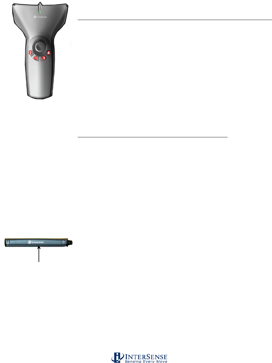
InterSense Doc. No. 072-00105-0I07 Rev. 4.2
IS-900 User Guide Page 70 of 177
Data Item 22 – Buttons.
One 3-digit integer in ASCII format or one byte in binary format.
Bits represent the button states of a station’s buttons. If a button
is pressed, the corresponding bit is 1 otherwise it is 0. The bit
assignments for the wand are (where bit 0 is the least significant
bit):
Bit
Button
MicroTrax Wand button
0
1
1 on wand image
1
2
2 on wand image
2
3
3 on wand image
3
4
4 on wand image
4
5
center (press joystick)
5
6
trigger
Data Item 23 – Joystick.
Two integers, one for each axis, values ranging from 0 to 255.
Two 3-digit integers in ASCII format or two 1-byte unsigned
values in binary format. Values at limits and at center are:
Axis
Position
Value
left/right (1st integer)
left
0
center
127
right
255
front/rear (2nd integer)
rear
0
center
127
front
255
Define Tip Offsets N{stationNum},[Ox, Oy, Oz]<>
By default, the point being tracked is for each station is:
Wand Station: Tip.
Head Tracker Station: Intersection of front surface, bottom
surface and at mid length, see image to the left.
Hand Tracker Station: center top, in dent.
This command allows the user to define a set of position
offsets, so a different point can be tracked. Offsets are
measured in the body coordinate frame of the MicroTrax
station and are entered in centimeters. If optional
parameters are omitted, current settings are returned.
Default 0,0,0
Tip Offset: intersection of
front surface and bottom
surface and at mid
length.

InterSense Doc. No. 072-00105-0I07 Rev. 4.2
IS-900 User Guide Page 71 of 177
Position Operational Envelope
V{stationNum},[Xmax, Ymax, Zmax, Xmin, Ymin, Zmin]<>
This command sets the boundaries of the area where
position is to be tracked. Whenever a station leaves the
defined range, position tracking is stopped and only
resumed once it is back within the defined boundaries.
Parameters are entered in meters. If optional parameters
are omitted, current settings are returned. Units are
meters.
Default 200,200,200,-200,-200,-200
4.3. Fastrak™ Commands Implemented for Compatibility
Hemisphere H{stationNum},[p1,p2,p3]<>
Sets the tracking hemisphere for a magnetic tracking
system. Because InterSense trackers are not magnetic
the parameters are ignored. However, they can be set and
then queried for compatibility with software such as
MultiGen SmartScene or Immersion Corporation haptic
Software. If optional parameters are omitted, a data record
containing current Hemisphere settings for the station is
returned.
Default 1,0,0
4.4. InterSense specific Commands
All InterSense specific commands start with the letter M (for “Manufacturer-specific”) and must be
completed by a CR,LF pair.

InterSense Doc. No. 072-00105-0I07 Rev. 4.2
IS-900 User Guide Page 72 of 177
4.4.1. System Configuration Commands
Time Units The time stamp recorded is the time when the tracker data
was collected from the hardware. The time index is set to
zero when tracker is first turned on.
MT<> Sets the units for the data record time stamp to
milliseconds.
Mt<> Sets the units for the data record time stamp to
microseconds.
Default T
Set Current Time to Zero MZ<> This command sets current time index of the
tracker to zero.
Set Ethernet Communication Parameters
MEthIp{address}<> Sets System IP address.
Use dotted format like 192.168.1.1. If address is omitted,
the current address is returned, 31EI[address]<>. The IP
address takes effect immediately unless an address was
already set, in which case system settings must be saved
and the system must be restarted.
MEthTcpPort{port}<> Sets TCP communication port.
MEthUdp{state}<> Sets state of UDP broadcast.
1=enabled, 0=disabled
MEthUdpPort{port}<> Sets UDP broadcast port.
MEthSubnet{subnet}<> Sets network subnet.
MEthMode{mode}<> Sets network subnet.
2=DHCP, 1=manual, 0=disabled
MEthApply<> Apply Ethernet settings (settings must be
saved to make this permanent).
Default Ethernet communications settings:
UDP state OFF
UDP port 5001
TCP port 5005
Subnet 255.255.255.0
IP address None

InterSense Doc. No. 072-00105-0I07 Rev. 4.2
IS-900 User Guide Page 73 of 177
InterSense System Status Record Request
MS<> Request the manufacturer-specific system status
record. This is information about parameters which
are specific to the InterSense product, additional to
the standard system status information obtained
using the S command.
Tracking Status Record Request
MP<> Requests tracking status information for all 12
stations. See Section 5.5.5 for the description.
Ultrasonic Timeout Interval
MU[interval]<> This command has no effect with the IS-
900.
Default N/A
Ultrasonic Receiver Sensitivity
Mg[Level]<> This command has no effect with the IS-900.
Default N/A
Genlock Synchronization MG[State, Rate]<>
State 0 – Genlock is off (free run)
1 – Reserved
2 – External sync, manual (supply strobe rate)
3 – Internal sync, supply output record rate
Rate Value in Hertz used with State = 2 and 3
Default 0
Genlock Phase MGP[Param]<>
Param can be the Phase (0 to 100%) or ‘+’ to increase to
the next phase point, or ‘-‘ to decrease to the next phase
point. Please see Appendix F for complete details.
Default 0
Genlock Sync Source MGS[source]<>
source 1 – TTL
2 – NTSC

InterSense Doc. No. 072-00105-0I07 Rev. 4.2
IS-900 User Guide Page 74 of 177
Configuration Lock Configuration lock commands are used to prevent unintentional
changes to tracker configuration. Two Levels of protection are
provided. The First prevents changes to saved settings. The
second prevents changes to current unsaved (session) settings as
well as saved settings.
MConfigLockMode[mode]<>
Mode
0 Lock off
1 Lock saved settings
2 Lock saved and session settings
Default 0
In mode 1 (lock saved settings), the Fastrak commands to
save current (^K) and restore factory (W) settings are
disabled. In mode 2 (lock saved and session settings), the
Fastrak command to restore saved settings (^Y) is
disabled as well as ^K and W. In mode 0 (lock off), ^Y, ^K
and W are all enabled. When mode is changed, it is saved
to nonvolatile memory without affecting any other saved
settings. If mode is omitted, the current setting is returned.
The LCD menu options to save and restore settings are
not affected by lock mode.
SoniStrip LED control ML[state]<>
If state is 0, the blue LEDs on the SoniStrips are disabled. Visual
confirmation of the operation of the ultrasonic system is important,
so don’t disable the LEDs unless they interfere with your
application.
Default 1
Beacon Scheduler MSchAlg[n]<>
Selects beacon Scheduling Algorithm. If n is 1, a distance-based
algorithm is used. This algorithm chooses beacons based on
distance only. If n is 2 a directional algorithm is used which
chooses beacons based on orientation as well as distance.
Default 2
Error reporting Hardware and configuration errors are stored internally and can
be reported to the application. If the application is not setup to
accept error messages, or if you are not sure, error reporting
should be disabled. This setting is not saved with tracker
configuration, so error reporting is off every time tracker is turned
on.

InterSense Doc. No. 072-00105-0I07 Rev. 4.2
IS-900 User Guide Page 75 of 177
ME<> Returns all errors, one per error message.
MEC<> Clear all errors from internal list.
ME1<> Enable error reporting.
ME0<> Disable error reporting.
Default Error reporting is OFF
Command logging Command logging captures all host commands into a file
for debugging purposes. The log file holds a maximum of
500 kB. When the max size is reached, the file is rewound
and overwritten with new entries. Long series of P and MP
commands are abbreviated to save space. The command
logging state is also indicated on the LCD (see Section 5).
Command logging control is available on the LCD menu
under System ConfigCommand Log: Enable Log,
Disable Log and Clear Log. It is accessed by the following
command set.
MLogOpen<> Enables logging. If settings are
saved, logging will remain on
through reset. An existing log file is
always appended to.
MLogClose<> Disables logging.
MLogClear<> Disables logging and deletes log file.
Use MLogOpen to resume logging.
MLogState<> Returns logging state (0=off, 1=on),
31LS{0,1}<>
MLogSend<> Outputs log file to host one
command per line.
31LF<timestamp in
ms>:<command><>
the timestamp is a decimal number
and is not zero-padded. The log file
can alternatively be retrieved using
ISDEMO (see section 10).
4.4.2. InterSense-specific Station Parameters
InterSense Station Status Record Request
Ms{stationNum}<>
Request an individual sensor status record for stationNum.
This is information about parameters which are specific to
the InterSense product.
Prediction Interval Mp{stationNum},[Interval]<>
Sets the time-interval of prediction for stationNum. Interval
is an integer number of time in milliseconds. Suggested

InterSense Doc. No. 072-00105-0I07 Rev. 4.2
IS-900 User Guide Page 76 of 177
range is 0-50 ms. This parameter is used for both position
and orientation prediction. If optional parameter is omitted,
current prediction value is returned.
Default 0
Perceptual Enhancement Level
MF{stationNum},{Mode}<>
In order to provide the best performance for a large range
of various applications, 3 levels of perceptual
enhancement are available. None of the modes
introduces any additional latency.
Mode 0 provides the best accuracy. The drift correction
adjustments are made immediately; no jitter reduction
algorithms are used. This results in somewhat jumpy
output (not recommended for head-tracking) but with lower
RMS error. Use this mode for accuracy testing or for any
application that requires best accuracy.
Mode 1 provides accuracy similar to that of mode 0, with
an addition of a jitter reduction algorithm. This algorithm
reduces the accuracy by only a small amount and does not
add any latency to the measurements.
Mode 2 is recommended for use with HMD or other
immersive applications. The drift correction adjustments
are made smoothly and only while the sensor is moving, so
as to be transparent to the user.
Default 2
Compass Heading Correction
MH{stationNum, mode}<>
Turns on the stationNum’s compass heading correction. To
operate effectively, the magnetic field in the environment
needs to be homogeneous. Only valid when an
InertiaCube is being used as a station (i.e. not valid for
MicroTrax devices).
For an InertiaCube, the modes are defined:
Mode 0 - Compass is OFF, no heading compensation is
applied. Not recommended, Modes 1 or 2 are preferred.
Mode 1 - Partial compass mode. Magnetometer readings
are used to reduce drift and maintain stability, but not as an
absolute measurement system. In this mode, system is

InterSense Doc. No. 072-00105-0I07 Rev. 4.2
IS-900 User Guide Page 77 of 177
much less susceptible to magnetic interference, but heading
drift will slowly accumulate. This mode is particularly useful
when high rotational sensitivity settings are used.
Mode 2 - FULL compass mode. Readings produced by the
magnetometers inside the InertiaCube are used as the
absolute reference orientation for yaw.
Default 2
Mh{stationNum}<>
Turns off the stationNum’s compass heading correction.
There can be slow drift in the yaw direction. Only valid
when an InertiaCube is being used as a station (i.e. not
valid for MicroTrax devices).
Rotational Sensitivity Level
MQ{stationNum},[Sensitivity Level]<>
Adjusts rotational sensitivity of a station when the
Perceptual Enhancement Level is set to level 2. Sensitivity
Level is an integer 1 to 4 where 1 is the lowest and 4 is the
highest sensitivity. It is recommended that sensitivity be
set to 4 when enhancement is set to level 1. If optional
parameter is omitted, current value is returned.
Default 3
4.4.3. Station and Constellation Configuration Commands
This section describes the commands used to assign sensing devices to the logical components
of the tracking system. Such devices with the IS-900 are SoniStrips and the SoniDiscs (beacons)
that make up the Constellation Array. All commands in this section start with MC.
A Configuration Session is the period during which MC commands are received and accepted. It
starts when the first MC command arrives and ends when these commands are explicitly
activated with the MCe<> (or discarded with the MCx<>) command.
Associate Fixed PSE with a Constellation
MCF{FPSE number},{xp, yp, zp, xn, yn, zn, IDcode}<>
Configures or adds a Fixed PSE. For IS-900 FPSE is a
SoniDisc ultrasonic transponder beacon. If only the FPSE
number parameter is present then current data for that
PSE is returned on the serial port. If that PSE is not
configured, record will contain Hardware ID of -1. If no
parameters are provided then data for all configured Fixed
PSEs is returned, each PSE in a separate record. This
command does not take effect until explicitly activated by
the MCe<> command.
FPSE number

InterSense Doc. No. 072-00105-0I07 Rev. 4.2
IS-900 User Guide Page 78 of 177
A Unique number identifying a Fixed PSE (beacon) within
a Constellation (a complete set of fixed PSEs). Numbering
starts at 1.
xp, yp, zp FPSE position in meters.
xn, yn, zn Normal vector.
IDcode Hardware ID of the PSE.
<> CR LF pair.
Disassociate Fixed PSE from the Constellation
MCf[Fixed PSE number, IDcode]<>
If PSE number and IDcode are not associated in the
current configuration, this command is ignored. This
command does not take effect until explicitly activated by
the MCe<> command.
Clear All Fixed PSEs (Constellation) Command
MCC<>
Delete all Fixed PSEs from the configuration. This
command does not take effect until explicitly activated
by the MCe<> command.

InterSense Doc. No. 072-00105-0I07 Rev. 4.2
IS-900 User Guide Page 79 of 177
Apply New Configuration MCe<>
This command reconfigures the system with the new
MicroTrax station and SoniDisc information. A
Configuration Session is the period during which the
station and constellation configuration commands are
received and accepted. The configuration session starts
when the first MC command arrives. MC commands are
saved but not applied to the system configuration until the
MCe<> command is received. This command executes all
MC commands received since the start of the
Configuration Session and computes the new system
state.
Cancel Configuration Session
MCx<>
Cancel the configuration session command. All MC
commands received during the session are discarded.

InterSense Doc. No. 072-00105-0I07 Rev. 4.2
IS-900 User Guide Page 80 of 177
4.5. Records Returned from the Tracker to the Host
4.5.1. Format Considerations
Record Headers
The first byte of each record is used to identify its type.
0 – Data record.
2 – Fastrak™ status record.
3 – InterSense manufacturer-specific status record.
Floating Point Numbers
Floating point numbers can be returned as IEEE 32 bit floats or as ASCII numbers in X.xf
notation, where:
X is the total number of characters used to represent the float.
x is the number of digits after the floating point.
f is a symbol indicating that number is a float.
For example, number -42.6 in 10.4f format would look as follows: “-42.6000”
4.5.2. Status Record Hexadecimal Character Decoding
System Status, Manufacturer Status, and Manufacturer Station records use Hexadecimal
Characters to encode status data. Each character can be 0 to F and can encode 4 bits. Logical
AND operator can be used to test specific bits. Please see following code example:
unsigned short byte1, byte2, byte3;
char hexChar[2];
hexChar[1] = 0x00;
hexChar[0] = statusRecordBuffer[3];
sscanf(hexChar,"%x", &byte1);
hexChar[0] = statusRecordBuffer[4];
sscanf(hexChar,"%x", &byte2);
hexChar[0] = statusRecordBuffer[5];
sscanf(hexChar,"%x", &byte3);

InterSense Doc. No. 072-00105-0I07 Rev. 4.2
IS-900 User Guide Page 81 of 177
4.5.3. Fastrak™ System and Data Records
Data Record This record is sent in response to the P command in polled
mode or continuously in continuous mode. A separate data
record is sent for each active station. The list of data items
in each station record depends on how the list was set up
with the O command. For most of the commonly used data
list items, the format depends on commands F, f, U, u, MT,
Mt.
0{stationNum}{status}{dataItem1,dataItem2,....}
stationNum
A hexadecimal number up to C (decimal 12)
status An ASCII space character. This status byte is
currently unused.
dataItemX
ASCII In ASCII numbers, set with the F command, any
numbers returned as floats are returned as
ASCII numbers. Each number is 7 ASCII
characters: a sign, 3 digits, a decimal point and
2 more digits. If programming in C use
scanf(“%7.2f”, &value) to read them.
Binary In binary mode, set with the 'f' command, the
floats are sent as 4 byte IEEE 32-bit floats.
Time Stamp 32 bit floating point number
ASCII In ASCII mode it is allowed 14 characters and is
displayed as an integer (digits after the floating
point are ignored).
Binary In binary mode it is returned as a 32 bit float.
Binary16 mode
Set by selecting 18, 19 and/or 20 only with the
O command. This is the fastest way to get data
but the most difficult to decode and the least
accurate.

InterSense Doc. No. 072-00105-0I07 Rev. 4.2
IS-900 User Guide Page 82 of 177
Example: For the default data record O1,2,4,1<> in ASCII mode 'F'.
The output record set for the active stations 1 and 2 would
look as follows:
'01 1.23 41.83 12.18 13.04 76.11 34.12CRLF'
'02 23.01 -452.94 0.01 -1.01 23.32 12.34CRLF'
Station 1: x=1.23, y=41.83, z=12.18, yaw=13.04, pitch=76.11, roll=34.12
Station 2: x=23.01, y=-452.94, z=0.01, yaw=−1.01, pitch=23.32, roll=12.34
System Status Record This record is sent in response to the S command. It
contains system wide status information. Some of the
information in the status record must be bit decoded.
21S{statusRecord}<>
Bytes Explanation
1 Record type, '2'
2 Station Number. Always '1'
3 Sub-Record type, 'S'
4 Config Hex Char 0
5 Config Hex Char 1
6 Config Hex Char 2
7-9 BIT error. Currently unused.
10-15 Blank
16-21 Firmware version ID
22-53 System Identification
54-55 CR, LF
To decode each of the Config bytes
Config Hex Char 0 Unused
Config Hex Char 1 Unused
Config Hex Char 2
Bit Meaning
0 Output Format (0= ASCII, 1=Binary)
1 Output Units (0=Inches, 1= Centimeters)
2 Unused
3 Transmit Mode (0 = Polled, 1 = Continuous)
Output List Record This record is sent in response to an O{stationNum}<>
command. It returns the list of currently selected output
parameters for that station, 2 bytes per item.
2{stationNum}O{par1par2...parN}<>
Bytes Explanation
1 Record type , '2'

InterSense Doc. No. 072-00105-0I07 Rev. 4.2
IS-900 User Guide Page 83 of 177
2 Station Number. A hexadecimal number up to
C.
3 Sub-Record type, 'O'
4-5 par1
6-7 par2
… CR, LF
For example, the default data list would be returned as:
'21O 2 4 1<>'
Station State Record This record is sent in response to an l{stationNum}<>
command. If the stationNum parameter is omitted the record
returns the state of the first four stations. This maintains
compatibility with the Fastrak protocol. If stationNum is
stated then byte 4 of the record will contain the state of the
requested station. Bytes 5, 6, and 7 will contain the state of
stations 2, 3, and 4. If stationNum is replaced with the ‘*’
wild-card character, then status for 32 stations is returned in
a single record.
Output of values are interpreted as 1 for ON and 0 for
OFF.
2{stationNum}l{stat1stat2stat3stat4}<>
Bytes Explanation
1 Record type , '2'
2 Station Number. 1, 2, 3, 4
3 Sub-Record type, 'l'
4 State of station stationNum, or station 1 if
omitted.
5 State of station 2.
6 State of station 3.
7 State of station 4.
8-35 (if ‘*’) Status of stations 5 to 32.
8,9 or 36,37 CR, LF
For example, if stations 1 and 3 are on:
l1<> command will return ‘21l1010<>’
l*<> command will return ‘21l10100000000000000000000000000000<>’

InterSense Doc. No. 072-00105-0I07 Rev. 4.2
IS-900 User Guide Page 84 of 177
Alignment Reference Frame Record
This record is sent in response to an A{stationNum}<>
command. It returns 9 ASCII floats that were last set with
the A command. Each float is represented as 7 characters
with 2 digits after the floating point. Units are centimeters.
2{stationNum}A{OxOyOzXxXyXzYxYyYz}<>
Bytes Explanation
1 Record type , '2'
2 Station Number. A hexadecimal number up to C.
3 Sub-Record type, 'A'
4-24 OxOyOz - origin coordinates
25-45 XxXyXz - vector in the direction of the positive x
axis
46-66 YxYyYz - vector in the direction of the positive y
axis
67-68 CR, LF
Boresight Reference Angles Record
This record is sent in response to a G{stationNum}
command. It returns 3 ASCII floats that were last set with
the G command. Each float is represented as 7 characters
with 2 digits after the floating point. Units are degrees.
2{stationNum}G{yawref pitchref rollref}<>
Bytes Explanation
1 Record type , '2'
2 Station Number. A hexadecimal number up to
C.
3 Sub-Record type, 'G'
4-10 yawref - azimuth reference angle
11-17 pitchref - elevation reference angle
18-24 rollref - roll reference angle
25-26 CR, LF
Hemisphere Record This record is sent in response to an H{stationNum}<>
command. It returns 3 ASCII floats that were last set with
the H command. Each float is represented as 7 characters
with 2 digits after the floating point.
2{stationNum}H{p1p2p3}<>

InterSense Doc. No. 072-00105-0I07 Rev. 4.2
IS-900 User Guide Page 85 of 177
Tip Offset Record This record is sent in response to an N{stationNum}<>
command. It returns 3 ASCII floats that were last set with
the N command. Each float is represented as 7 characters
with 3 digits after the floating point. Units are centimeters.
2{stationNum}N{Ox Oy Oz}<>
Bytes Explanation
1 Record type , '2'
2 Station Number. A hexadecimal number up to
C.
3 Sub-Record type, 'N'
4-11 Ox – X-direction tip offset
12-19 Oy – Y-direction tip offset
20-27 Oz – Z-direction tip offset
28-29 CR, LF
Position Operational Envelope Record
This record is sent in response to a V{stationNum}<>
command. It returns 6 ASCII floats that were last set with
the V command. Each float is represented as 7 characters
with 2 digits after the floating point. Units are meters.
2{stationNum}V{Xmax,Ymax,Zmax,Xmin,Ymin,Zmin}<>
Bytes Explanation
1 Record type , '2'
2 Station Number. A hexadecimal number up to
C.
3 Sub-Record type, 'V'
4-11 Xmax – Maximum X-direction value
12-19 Ymax – Maximum Y-direction value
20-27 Zmax – Maximum Z-direction value
28-35 Xmin – Minimum X-direction value
36-43 Ymin – Minimum Y-direction value
44-51 Zmin – Minimum Z-direction value
52-53 CR, LF

InterSense Doc. No. 072-00105-0I07 Rev. 4.2
IS-900 User Guide Page 86 of 177
4.5.4. InterSense-specific Records
Manufacturer System Status Record
This record is sent in response to an MS<> command. It
returns a status record specific to the InterSense system.
31S{statusRecord}<>
Bytes Explanation
1 Record type , '3'
2 Station number. Always '1'
3 Sub-Record type, 'S'
4 Config Hex Char 0
5 Config Hex Char 1
6 Config Hex Char 2
7,8 CR, LF
To decode each of the Config Hex Characters
Config Hex Char 0 Reserved
Config Hex Char 1 Reserved
Config Hex Char 2
Bit Meaning
0 Reserved
1 Boresight Compatibility Mode (0 = Firmware Version
2.x, 1 = FASTRACK)
2 Time units (0 = milliseconds, 1 = microseconds)
3 ReceiverPod LEDs (0 = OFF, 1 = ON)
Manufacturer Station Record
This record is sent in response to the Ms{stationNum}<>
command. It returns a station status record specific to the
InterSense system.
3{stationNum}s{statusRecord}<>
Bytes Explanation
1 Record type , '3'
2 Station number. A hexadecimal number up to C.
3 Sub-Record type, 's'
4 Config Byte 0
5 Config Byte 1
6 Config Byte 2
7,8 CR, LF
To decode each of the Config bytes

InterSense Doc. No. 072-00105-0I07 Rev. 4.2
IS-900 User Guide Page 87 of 177
Config Byte 0 Unused
Config Byte 1 Corresponds to the Perceptual Enhancement
Level. Can be 0, 1, or 2. The remaining 2 bits are
reserved for future expansion of this option.
Config Byte 2
Bit Meaning
0 Reserved
1 Heading Compensation Mode bit 1
2 Heading Compensation Mode bit 2
3 Reserved
Heading compensation bits are translated as:
00 – Compass mode 0 (compass is off)
01 – Compass mode 1 (Partial compass mode)
10 – Compass mode 2 (Full compass mode)
Prediction Interval Record This record is sent in response to Mp{stationNum}<>
command. It returns an ASCII integer for the number of
milliseconds of prediction.
3{stationNum}p{interval}<>
Bytes Explanation
1 Record type , '3'
2 Station Number. A hexadecimal number up to C.
3 Sub-Record type, 'p'
4-5 Prediction interval.
6,7 CR, LF
Sensitivity Level Record This record is sent in response to MQ{station number}<>
command. It returns the current sensitivity settings of a
station. This setting is only relevant when Perceptual
Enhancement level is set to 1 or 2.
3{Station Number}Q{Sensitivity Level}<>
Bytes Explanation
1 Record type , '3'
2 Station Number. A hexadecimal number up to C.
3 Sub-Record type, 'Q'
4 Sensitivity level 1 to 5
5,6 CR, LF

InterSense Doc. No. 072-00105-0I07 Rev. 4.2
IS-900 User Guide Page 88 of 177
Genlock Synchronization Record
This record is sent in response to MG<> command. It
returns the current synchronization settings of the system.
31G{State}, {Rate}, {Number of cycles per signal}<>
Bytes Explanation
1 Record type , '3'
2 Always 1.
3 Sub-Record type, 'G'
4 State, 0 to 3
5-11 Strobe rate or Output record rate
12-14 Number of computational cycles tracker performs
between sync signals or output records. Multiply
this parameter by Rate to determine the internal
update rate of the tracker.
15,16 CR, LF
4.5.5. Records Specific to IS-900 Models
Ultrasonic Timeout Record This record is sent in response to the MU<> command. It
returns an ASCII integer for the number of milliseconds of
the ultrasonic timeout.
31U{Interval}<>
Bytes Explanation
1 Record type , '3'
2 Station Number. Always 1.
3 Sub-Record type, 'U'
4,5 Ultrasonic timeout value.
6,7 CR, LF
Ultrasonic Sensitivity Record
This record is sent in response to the Mg<> command. It
returns an ASCII integer representing current sensitivity
setting of the ultrasonic receivers.
31g{Level }<>
Bytes Explanation
1 Record type , '3'
2 Station Number. Always 1.
3 Sub-Record type, 'g'
4 Sensitivity Level.
5,6 CR, LF

InterSense Doc. No. 072-00105-0I07 Rev. 4.2
IS-900 User Guide Page 89 of 177
Fixed PSE Record This record is sent in response to MCF[Fixed PSE
number]<> command. It returns the current settings of a
single PSE or entire Constellation.
31F{Fixed PSE number}{Fixed PSE record}<>
Bytes Explanation
1 Record type , '3'
2 Constellation Number. Always '1'
3 Sub-Record type, 'M'
4-10 Fixed PSE number in ASCII decimal format.
11-40 x, y, z components of position vector in 10.4f ASCII
format. Values are in meters.
41-61 x, y, z components of normal vector in 7.2f ASCII format
62-68 Hardware ID code in ASCII format.
69,70 CR, LF
Tracking Status Record Sent in response to MP<> command. It returns the tracking
status information for all 12 stations. Range measurement is
defined as an ultrasonic signal received by a single URM.
For example, if the system is configured with two URMs and
six ultrasonic beacons (SoniDiscs), 12 range measurements
per cycle could be received.
31P{Tracking state record}<>
Bytes Explanation
1 Record type, 3'3'
2 Station Number. Always 1.
3 Sub-Record type, 'P'
4 Tracking state identifier for station 1. State can be L
if lost, T for tracking, or X for invalid. Please see
Section 4.2.10 of this manual for complete
description.
5 Number of range measurements received this cycle.
6 Number of range measurements rejected.
. …
3+3*N Tracking state identifier for station N.
. …
40-44 Update rate per station.
45 Not used, always blank.
46 Genlock identifier. Can be G for Genlock on and
synchronized, X if Genlock on but not synchronized, or
blank if Genlock is off.
47,48 CR, LF
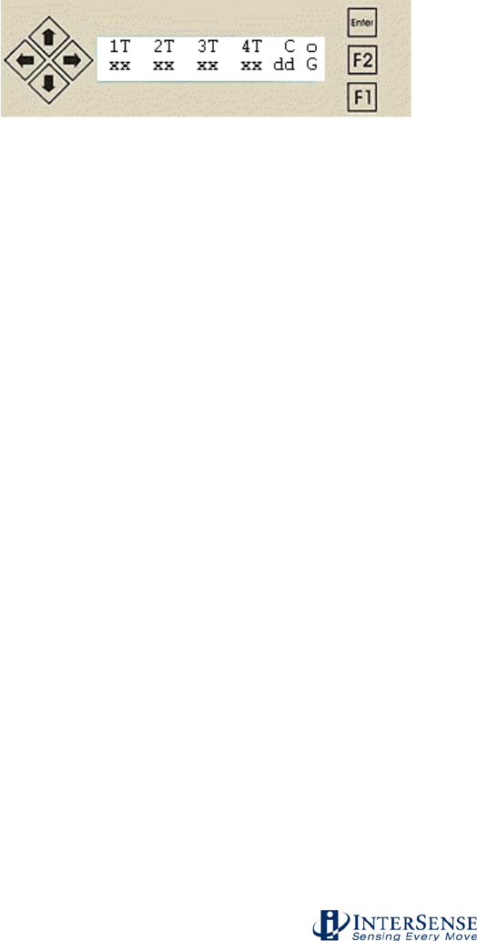
InterSense Doc. No. 072-00105-0I07 Rev. 4.2
IS-900 User Guide Page 90 of 177
5. LCD Status & Settings Screen
(Firmware 4.26 and higher)
5.1. Overview
The LCD Status and Settings screen provides a simple and convenient way to view and change
most of the tracking parameters, communication protocols, and IS-900 system settings without
the requirement of a dedicated Windows PC running ISDEMO. The LCD panel also provides a
simple way to place the IS-900 in “file transfer” communication mode for installing firmware
updates.
There are 7 buttons provided for status/menu navigation: Up, Down, Right, Left, Enter, F2, and
F1 (see Figure 35).
Figure 35 - IS-900 LCD Status & Settings Screen
Command logging indicator is the "C" field. If logging is off, the indicator is blank. If logging is on,
it is "C". If logging is on and the log file has wrapped (overflowed), the indicator is "W".
The “G” indicates GENLOCK is on and an “X” in its place indicates GENLOCK in on, but the
GENLOCK signal is not valid. A blank field indicates that GENLOCK is off. See Appendix X to
learn about GENLOCK.
In display mode, "xx" is the statistic indicated by the "dd" field. The up/down arrows rotate
between the possible statistics.
Statistics - when the field “dd” is replaced by:
RC Indicates the number of measurements received.
RJ Indicates the number of rejected measurements.
CI Indicates wireless communication integrity (100% when running wired)*
TQ An overall measure of tracking quality (nominally > 80%)
MQ An overall measure of ultrasonic range quality (nominally > 95% when still)
*NOTE: If the tracking device is running wired and the CI is less than 100%, then a faulty wire or
connection is probable. Power down and reseat all connections. Contact InterSense if condition
continues.
In display mode, the rotating “~o~” located in the upper right corner of the LCD panel is an
indication of IS-900 Processor health operation. If the rotating “~o~” is replaced by an “E”, then
an error has occurred in the IS-900 processor. Not all errors are serious, and can sometimes be
cleared using the LCD menu with no ill effect on the system. The LCD menu will also let you
determine the error code(s) which are referenced in Section 10.
Buttons for display mode:
Enter Transitions to menu mode.
Right/Left Selects next/previous group of stations for status display.
Up/Down Switches between measurements received, measurements rejected,
tracking quality, and communication integrity.
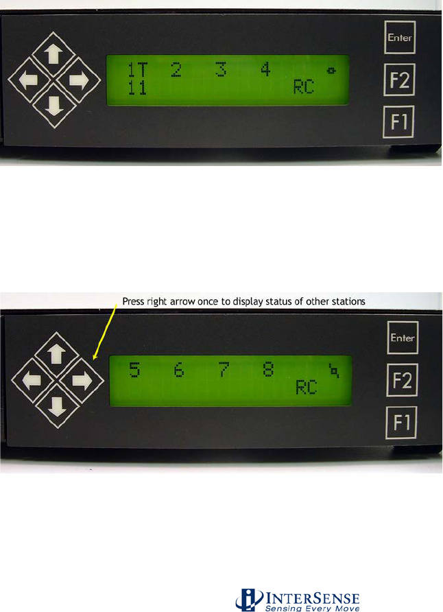
InterSense Doc. No. 072-00105-0I07 Rev. 4.2
IS-900 User Guide Page 91 of 177
Buttons for menu mode:
Enter Select menu item at cursor or enter changed setting.
Up/Down Move cursor to another menu item.
Right/Left Scroll right/left when viewing error message.
F2 Back up to parent menu.
F1 Return to display mode.
5.2. Normal Operation (Steady State)
During system start-up, the LCD displays a greeting and draws dots along the bottom row. While
the dots are being drawn, “file transfer” mode can be invoked by pressing the F1 button.
Otherwise, the system begins initializing.
To show progress during initialization, a line of 8 dashes turns into squares from left to right as
each port is initialized.
After initialization, the LCD operates in 2 modes; display and menu. In display mode (Figure 36),
the LCD indicates the tracking status of 4 stations at a time.
Figure 36 - LCD Panel in Normal Display Mode (Tracking One Station)
If the system is running, the station status is displayed and the indicator at the upper right corner
of the display should rotate. A number and a letter along the upper row, starting on the left side
of the LCD panel, represent each tracking station. Pressing the right arrow button (as shown in
Figure 37) will bring the status of the remaining stations into view.
Figure 37 - Status Display of Additional Tracking Stations
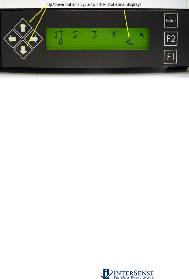
InterSense Doc. No. 072-00105-0I07 Rev. 4.2
IS-900 User Guide Page 92 of 177
In Figure 36, the “T” indicates that Station 1 (or the Tracker connected into port 1 of the
processor) is tracking. The “T” field next to each station number has different letter values that
indicate:
“T” = The station is tracking.
“X” = The station status is invalid or wireless channel is off.
“L” = The station is lost.
“ ” = No station is connected or the station state is “off”.
The statistics field below the station status is used to provide quick feedback of tracking
performance for each station. As shown in Figure 36, the “RC” shows that 11 ultrasonic
measurements where received and used during the last measurement cycle of this tracking
station.
Pressing the up/down buttons will cycle through the other statistics displays. Figure 38 shows a
zero value for the “RJ” or rejected measurement field indicating that all ultrasonic measured
values where used (none where rejected) during the last measurement cycle.
Figure 38 - Rejected Measurement Status for Tracking Station 1
The statistical values for “CI” or communication integrity (shown in Figure 39) are represented by
a percentage from 0 to 100%. 100% indicates the station is communicating with no errors or
missing records. For wired tracking stations, this value will always be 100%. If a station is
disconnected, it shows 0%. Anything in between might indicate a poor connection or an
excessive length of cable for a wired tracker, or for a wireless tracker, may indicate a weak signal
or radio frequency interference.
Wireless stations, typically show 90-100% because some records are lost or corrupted due to the
nature of the radio link. Lower percentages can occur when Wireless MicroTrax devices are set
to adjacent channels, or if interference from a source like a heavily used wireless LAN is present.
If a wireless station drops below about 30%, the link is assumed down and shows 0% until it is re-
established. A wireless station also shows 0% while it is asleep. When a station drops to 0%, “X”
is displayed in place of “T” or “L” for that station on the LCD.
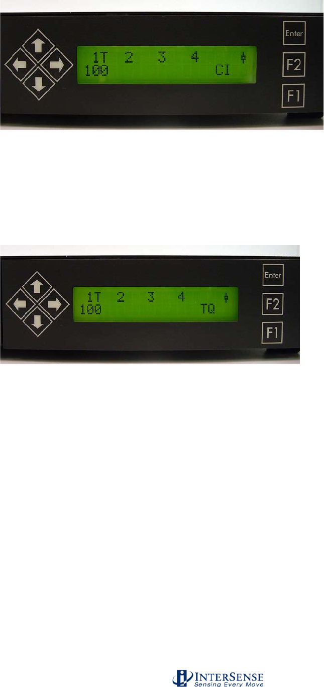
InterSense Doc. No. 072-00105-0I07 Rev. 4.2
IS-900 User Guide Page 93 of 177
Figure 39 - Communication Integrity Status for a Wired Tracking Station 1
The statistical values for “TQ” or tracking quality (shown in Figure 40) are represented by a
percentage from 0 to 100%. 100% means that the station is tracking perfectly and 0% means it is
lost. When an InertiaCube is plugged into a station port, the tracking quality is always 100%
because no ultrasonic measurements are used by 3-DOF devices such as InertiaCubes. For
MicroTrax devices, values anywhere in the range are possible.
This statistic is also available in the output data record item #75 indicating communication
integrity for a station. It ranges from 0 to 100, the same as the LCD value.
Figure 40 - Tracking Quality Status for a Wired Tracking Station 1
With MicroTrax devices, the number of measurements a station receives and the size of the
range errors of each measurement determine tracking quality. A station that receives a
measurement at each microphone in almost every measurement cycle, with an average range
error of less than 1 mm, will indicate 100%. The quality can drop to 0 if the station stops
receiving measurements or range errors get larger than 2 cm. Brisk motions or shock can also
temporarily reduce quality. It is typical to see a figure of 90% or higher for a motionless station
under good conditions with a well-calibrated Constellation. Loss of data from poor
communication integrity will also reduce the tracking quality.
This statistic is also available in the output data record item #40 indicating tracking status for a
station. In this data record, the value is 2.55 x TQ% (a range of 0 to 255).
Closely related to “TQ”, the “MQ” or measurement quality value indicates the average range
errors recorded in the ultrasonic measurement cycle. While the “TQ” value incorporates both the
range errors and number of measurements in its calculation, “MQ” is only concerned with range
errors (these can be displayed using the Diagnostics Screen mode in ISDEMO). Because range
errors primarily are due to the accuracy of the emitter positions, this value should be very high
(nominally 95%) for a stationary tracker as long as several emitters are being detected. Low
values, especially when moving slowly, often indicate mis-sighted or mis-configured
constellations.
“MQ” is output data record item #75.
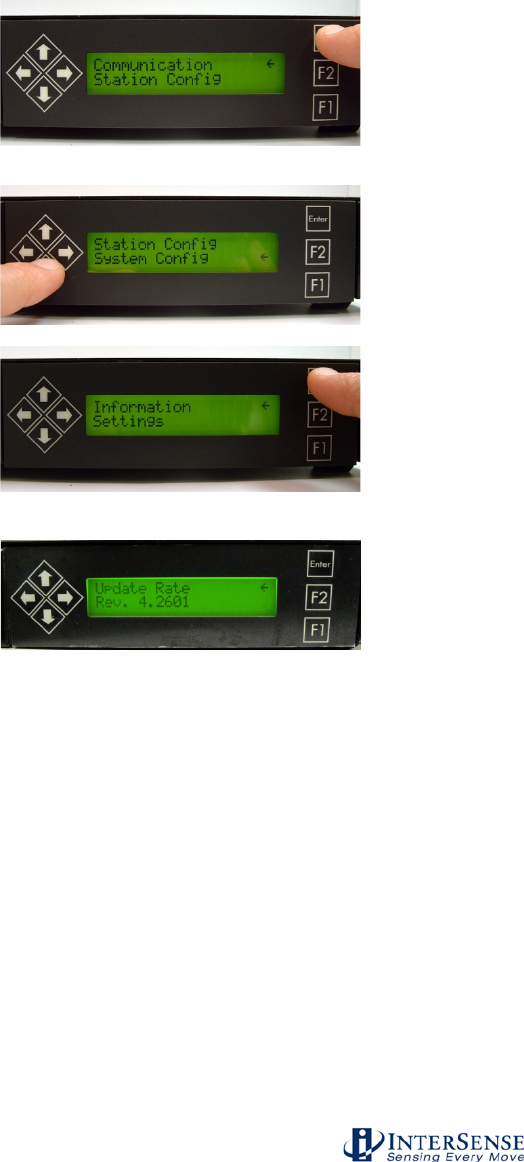
InterSense Doc. No. 072-00105-0I07 Rev. 4.2
IS-900 User Guide Page 94 of 177
Example of LCD Menu Navigation
As example of a typical use for the LCD panel, here are the steps to find out the current firmware
revision running on the IS-900. Refer to the menu flow chart in the next sectioin to follow the
navigation steps outlined here.
Step 1 – Change to Display mode
When the system is running with one tracker attached
at Port 1, the LCD is in display mode as shown in
Figure 36. The first step is to press the Enter key
which brings the LCD into the top menu of Menu
mode.
Step 2 – Scroll down to System Config
Use the down arrow keys to scroll to the system
configuration menu item.
Step 3 – Access the System Config submenu
Use the ENTER key to access the system
configuration submenu.
Step 4 – Access the Information submenu
Press enter to access the information submenu which
displays the current Firmware Revision of the IS-900.
If left alone, the LCD panel will automatically switch back to Display mode or pressing F1 will exit
the Menu mode directly. Pressing F2 will go up a single level in the menu tree.
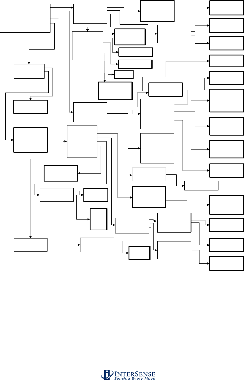
InterSense Doc. No. 072-00105-0I07 Rev. 4.2
IS-900 User Guide Page 95 of 177
5.3. IS-900 LCD Menu Flow Chart
Figure 41 illustrates the flow chart for the IS-900 LCD menu.
LCD menu flow chart for firmware versions 4.29 and greater.
Bold boxes represent decision points.
Communication
Station Config
System Config
Errors
Display
Reset Encoders (reserved)
Exit Menu
Baud Rate
Data Output
Ethernet
BACK
0. 9600 Baud
1. 19200 Baud
2. 38400 Baud
3. 115200 Baud
BACK
Binary Form
ASCII Form
BACK
Inches
Centimeters
BACK
Polled
Continuous
BACK
Format
Units
Sample Mode
BACK
Set Station
Config Station
View Station
BACK
Information
Settings
Genlock
Beacons
Command Log
Monitor
BACK
Set Station
XX #
Prediction
Sensitivity
Enhancement
Compass
State
BACK
View Errors
Clear Errors
BACK
0. Off
1. Bias
2. Full
BACK
0. None
1. Partial
2. Full
BACK
Station On
Station Off
BACK
1. Low
2. Medium
3. High
4. Max
BACK
Prediction:
XXms
Errors
#x xxxxxxH
Station [X]
State [X]
Enhancement [X]
Sensitivity [X]
Compass [X]
Prediction [X]
BACK
Set Group
XX #
Phase Point
xxx %
Output Rate
xxx Hz
Strobe Rate
xxx Hz
Rate: xxxx Hz
Update Rate
Rev. _____
BACK
Save Current
Restore Factory
Restore Saved
Set Config Lock
BACK
State
Phase
Source
BACK
Set Phase
Increase
Decrease
BACK
Genlock Off
External
Internal
BACK
0. Off
1. Saved
2. Saved/Session
BACK
LED Control
Volume
BACK
Set Group
Set Mode
BACK
Meas Received
Meas Rejected
Comm Integrity
Track Quality
Meas Quality
BACK
Enable Log
Disable Log
Clear Log
BACK
Broadcast On
Broadcast Off
UDP Port
BACK
UDP Port: xxxx
TTL
NTSC
BACK
Mode
IP Address
Subnet Mask
TCP Port
Apply
UDP Broadcast
BACK
0. Disabled
1. Manual
2. DHCP
BACK
IP Address
xxx.xxx.xxx.xxx
Subnet Mask
xxx.xxx.xxx.xxx
TCP Port
xxxx
LEDs On
LEDs Off
BACK
Min
Low
Med
Max
BACK
Figure 41 - IS-900 LCD Menu Flow Chart

InterSense Doc. No. 072-00105-0I07 Rev. 4.2
IS-900 User Guide Page 96 of 177
6. Appendix A – Frequently Asked Questions
Q1. What is the maximum length of the cable between the IS-900 MicroTrax Tracked
Devices and IS-900 Processor?
The cable between the IS-900 Processor and the MicroTrax Devices has been tested to a length
of 15 m (50 feet). This is the total length of cabling including the Tracker cable and the Tracker
Extension cable.
Q2. What is the maximum cable length from the IS-900 Processor to the SoniStrips?
The Processor to SoniStrip Cable, Part No. 078-00088-0030, can run a maximum length of 15
meters (50 ft). The maximum length of the total SoniStrip daisy chain measured from the IS-900
Processor to the end of the SoniStrip chain is 24 meters (80 ft.) without external power boosters.
The IS-900 SimTracker configuration can support a maximum of 12 SoniStrips (36 SoniDiscs) per
system. The IS-900 VETracker configuration can support 84 SoniStrips (252 SoniDiscs) split
between two ports with the use of external power boosters. With the power boosters, the
maximum length of the complete SoniStrip daisy chain measured from the IS-900 Processor to
the end of the SoniStrip chain can be greater than 90 meters (300 ft.). Please consult
InterSense for non-standard configuration support!
See Section 1.8 for full details on cabling.
Q3. What is the Mean Time Before Failure (MTBF) of the IS-900 system?
Based on supplier data, the MTBF for the IS-900 is estimated at 5 years.
Q4. What type of shock can the MicroTrax Tracked Devices sustain?
The individual inertial components in the MicroTrax Devices are designed to withstand a
maximum acceleration of 500 g. Basically this means that a direct impact on the devices is not
recommended and will most likely result in damaging the packaging, ultrasonic components
and/or calibration of the device.
Should your tracking components experience this type of shock, consult InterSense to determine
if repairs or recalibration are needed.
The MicroTrax devices can withstand a higher level of external shock if mounted on rubber, since
the acceleration experienced by the MicroTrax device itself is reduced. Also, InterSense
manufactures hardened tracking devices for industrial environments. Consult InterSense sales if
you require a hardened tracking device.
Q5. What are the PIN assignments on the RS-232 Serial Ports (DB9) on the IS-900
Processor?
Pin Function
1 DCD
2 RX
3 TX
4 DTR

InterSense Doc. No. 072-00105-0I07 Rev. 4.2
IS-900 User Guide Page 97 of 177
5 GND
6 DSR
7 RTS
8 CTS
9 RI
Q6. Do you have any advice about working with software packages?
InterSense maintains a list of software partners at http://www.intersense.com/softwarepartners.
Please check this web page and then consult with the software vendor to determine compatibility.
If the software package is not listed or you have any questions, contact InterSense technical
support at techsupport@intersense.com.
Q7. How do I know whether I have the latest release of ISDEMO?
Check our web site’s Support/Downloads section. The direct URL is
http://www.intersense.com/downloads. All versions of our product CDs are available for
download. We always post the latest release for you to download.
Q8. If my tracker is not working properly, how can I have it examined or repaired?
Please contact InterSense technical support at +1 781-541-7624, or email
techsupport@intersense.com. A support representative will assist you with troubleshooting the
tracker, and if it is determined that there is a hardware problem, can provide a return
authorization number to have it repaired. InterSense has a standard warranty of one year for all
serial-numbered items, which covers defects in materials and workmanship. Physical or electrical
damaged to equipment is not covered, with the exception of damage that is caused by another
InterSense device being properly connected to the damaged device, or in similar instances.
If your device is more than one year old, it can still be repaired by InterSense, but it may incur an
examination fee as well as charges for parts and labor. If you require warranty coverage on a
device or devices beyond one year, InterSense sells extended warranties in one-year increments
– please contact your sales representative for additional information or to purchase such a
warranty extension.

InterSense Doc. No. 072-00105-0I07 Rev. 4.2
IS-900 User Guide Page 98 of 177
7. Appendix B – Troubleshooting & Tips
Problem
Reason/Solution
ISDEMO doesn’t work /
can’t connect to IS-900
Most common reasons (not in any order):
1) Connected to wrong COM port plug on the back of the
computer.
2) The selected serial port is captured by another program
and can’t be opened by ISDEMO.
3) The RS-232 cable running from the PCTracker Hub to
the computer is not a null modem serial cable (crossed
TX and RX lines).
4) The RS-232 cable running from the IS-900 to the
computer is not a straight-through serial cable.
5) Not using Start Displaying Data (CTRL-D). It may be
necessary to select Stop Displaying Data (CTRL-X)
first.
6) Check the communication settings for proper
configuration with either Serial or Ethernet, depending
on the choice of host communications.
7) If connecting over Ethernet, you may need to save the
settings and power-cycle the IS-900 for them to take
effect. Also, verify that you are using a patch cable if
connected to a hub/switch or a crossover cable if
connected directly to a PC.
8) If connecting over Ethernet, ensure that you are on the
correct subnet. This means that the first three dotted
numbers are the same between the PC and IS-900, and
the subnet mask for the PC’s network card is
255.255.255.0.
ISDEMO is running, but
system does not track
Check for the following:
1) The IS-900 is not plugged in or the host connection is
not plugged in or configured properly. Check all power,
connections and Communication configuration in
ISDEMO.
2) The SoniStrips are not connected to, or detected by, the
IS-900 (the port they are connected to should have a
corresponding red LED lit to indicate they are
connected – if no red LED is lit, then try powering down
the IS-900, unplugging and replugging the cable, and
turning the IS-900 on again).
3) The SoniStrips may be connected to the processor with
an incorrect cable. The cables used between
SoniStrips and between a SoniStrip and the IS-900
should have 10 pins, and will typically have a blue band
around them. If your cable has 8 pins, it is a tracker
cable and cannot be used with SoniStrips.

InterSense Doc. No. 072-00105-0I07 Rev. 4.2
IS-900 User Guide Page 99 of 177
Tracker(s) are lost
Check for the following:
1) A valid constellation for the SoniStrips is loaded.
2) The small microphones on the MicroTrax Device(s) are
covered, upside down or the device is not located under
the SoniStrip constellation.
3) From the main ISDEMO window, run a self test by
selecting menu items “Tools System Self-Test” and
then from the Tracker Hardware and Configuration Test
window select menu item “Test Run Tests”. This
creates a window with text information about the
configuration of the system and will report is the IS-900
is communicating correctly to both the SoniStrips and
Tracker(s). This text file can be saved from the same
window using the menu item “File Save” and sent to
InterSense for technical support
(techsupport@intersense.com).
Orientation is drifting
uncontrollably
After power down, make sure that the MicroTrax Device is
properly plugged in and if running wireless a
communication channel is working.
Specific Troubleshooting Tips for Wireless Devices
ISSUE: The IS-900 Processor reports an X on the LCD for a wireless station
Run self-test using ISDEMO: Select:
Tools→System Self-Test→Test→Run Tests
At the bottom of the test report, check for error or warning messages:
Message
Possible Cause
Remedy
Link down for
station n
Transmitter is powered off or in sleep
mode or battery is discharged
Switch module power on, move
transmitter to wake it up, plug in
charger, respectively
MicroTrax is not plugged into
transmitter
Switch transmitter module off, plug in
MicroTrax, switch back on
Transmitter channel does not match
Base Receiver Module channel
In ISDEMO, select
Parameters→Wireless Configuration
to set up radios
Transmitter is out of range
Move transmitter and Base Receiver
Module closer together until
connection is reestablished
RF interference from another receiver
transmitter being used with another IS-
900 system in the area
Check for other receiver or transmitter
in the area that are powered on and
set to the same RF channel.
RF interference from other sources
Check for and turn off possible 2.4
GHz sources such as WLANs,
cordless phones, Bluetooth devices
Link ID for station n
doesn’t match initial
ID
MicroTrax was swapped out with
another unit while IS-900 processor
was on
Reset IS-900 Processor (if using
anonymous mode) or select
Parameters→Wireless Configuration
in ISDEMO to set up radios (if using
normal mode)
Wireless link could not be established
when the IS-900 Processor powered
up and the MicroTrax is not the same
Reset IS-900 Processor (if using
anonymous mode) or select
Parameters→Wireless Configuration
InterSense Doc. No. 072-00105-0I07 Rev. 4.2
IS-900 User Guide Page 100 of 177
unit on the station port the last time the
system was used
in ISDEMO to set up radios (if using
normal mode)
Interference from a transmitter being
used with another IS-900 system
Check for transmitter in the area that
is powered on and set to the same
channel.
Channels for
stations n and m
are both set to x
Receivers are set to the same channel
In ISDEMO, select
Parameters→Wireless Configuration
to set up radios
Link ID for stations
n and m are both x
MicroTrax units are not compatible
with each other
Contact InterSense
ISSUE: The Wireless Receiver Module Connection LED intermittently turns on and
off while using the system.
⇒ Try moving the Base Receiver Module to a different location, either further away from
other Base Receiver Modules or away from any large metal structures and/or closer
to the tracking area.
ISSUE: The Transmitter Module does not last more than 6 hours on a single
charge.
⇒ Make sure the charge light is off before you start to use the device to get the full
charge time.
If the device is over a year old and you have been using it regularly, it may be time to
replace the battery. Contact InterSense on how to return the device for the battery
replacement.
If the device is fully charged but only lasts a short time (less than 5 hours) there may be
a hardware failure. Contact InterSense on how to return the device for service. If you
suspect a hardware failure, do not continue to use the device - it could damage the
battery and cause a danger. See Battery Warnings at the beginning of this manual.
InterSense Doc. No. 072-00105-0I07 Rev. 4.2
IS-900 User Guide Page 101 of 177
8. Appendix C – Health & Safety Warnings with Tracker
Use Guidelines
Important:
Most of the side effects described in this section usually only occur when a tracking device, like
an IS-900, is used with personal displays or 3D glasses. The symptoms listed below usually
are referred to as “Simulator Sickness”.
Read and follow the user instructions.
Before using the IS-900, read and follow the user instructions. Also fully read
any 3rd party software or HMD instructions. In exceptional circumstances,
failure to read and follow the user instructions could result in possible side
effects that may lead to accidental injury during or after use.
Recommended.
For use only by persons 15 years of age or older. This system should not be
used by:
Persons under the influence of drugs and alcohol.
Pregnant women.
Persons suffering from a heart condition
Persons with a history of epilepsy.
Take frequent breaks.
It is recommended that the IS-900 should not be used for more than one hour
at a time in visually immersive applications. After an hour, you should take a
15-minute rest break before re-use regardless of how you feel. If you feel
uncomfortable at any time, stop using immediately.
Rest after using.
Rest for at least 15 minutes after using the IS-900 even if you feel fine and
have experienced none of the symptoms described below. If you have
experienced any undesirable effects or symptoms, rest until they are
completely gone. Do not walk, drive, ride a bike or operate equipment until you
have rested, otherwise you risk injury to yourself and others.
Epilepsy and seizures.
A very small part of the population has a condition that may result in epileptic
seizures or loss of consciousness. If you or anyone in your family has epilepsy
or has experienced seizures or loss of consciousness, do not use the IS-900
without first consulting your physician. Persons who have not experienced
seizures or loss of consciousness may still have an epileptic condition. We
recommend that a non-user is always present when the IS-900 is being used.

InterSense Doc. No. 072-00105-0I07 Rev. 4.2
IS-900 User Guide Page 102 of 177
Additional possible risks of harm.
While tracking technology has been used for many years, the range of sensors
that are used to calculate positional and angular data continues to develop.
Over the last twenty years as considerable amount of research has been
conducted into possible side effects induced in users of real time computing
systems that include various types of tracking sensors. This research has
reported the symptoms described below from some users of these systems.
The IS-900 is designed using the latest sensor technologies and we believe
that the possibility of such symptoms occurring is minimized. However, it is
not possible to design for the individual characteristics of each user and it is
possible that users will experience one or more of the side effects described
below. Historic research shows that the effects or symptoms ordinarily occur
during and immediately after use and should diminish quickly once the user
stops using the system.
We want you to make an informed and responsible choice about using the IS-
900. Accordingly, we warn you that even if you read and follow the User
Instructions, you may experience one or more of the following effects or
symptoms when using an IS-900 with a personal display: eye strain, altered
vision, eye or muscle twitching, headaches, neck and shoulder strain, nausea
and vomiting, disorientation, dizziness, impaired balance and stability,
drowsiness, fainting, fatigue, sweating, extreme paleness, impaired hand-eye
or other co-ordination.
Each effect or symptom, if it occurs, should be temporary and may last from a
few minutes to 30 minutes.
Tracker Use Guidelines
Keep the IS-900 MicroTrax tracking devices still for the first 10
seconds after starting your application software.
It is recommended, though not required, that you wait for the
MicroTrax devices to warm up (it achieves optimal performance after
warming up for at least 15-20 minutes).
The IS-900 system is tuned for normal head & hand motion. Avoid
shaking/vibration. Remember, this precision instrument uses angular
rate sensors, which sense smooth, regular movement very well.
If you keep these guidelines in mind, your IS-900 system will deliver superb
performance.

InterSense Doc. No. 072-00105-0I07 Rev. 4.2
IS-900 User Guide Page 103 of 177
9. Appendix D – Care & Maintenance
Care and Cleaning
When not in use, always return your IS-900 wireless devices (Wand and Wireless Transmitter) to
InterSense’s MicroTrax Docking Station or individual charger. The first step to keeping the IS-900
clean is to keep dirt and dust from accumulating. Try to keep the area around the system clear
and clean. Open ports in the rear of the base unit can quickly accumulate dust and dirt that can
affect their functioning.
Recommended cleaning materials are the same as those for computers. Antistatic cloths, which
not only clean the components, but also reduce static electricity, should always be used.
Cleaning solutions should be applied to the cloth and not directly on any part of the system
components.
Phone & email support
Any questions regarding the care and maintenance of your IS-900 system can be handled by
phone (781) 541-7624 (Toll Free in the US 888-359-8478 x7624) or by email
techsupport@intersense.com. Please see the Support page at www.intersense.com/support
for the technical support contact information.
Returns to InterSense
If you need to return a component to InterSense for replacement or repair, contact InterSense
prior to shipment to obtain a Return Authorization (RA) number. When calling, please look on the
back of IS-900 Processor to provide the serial number and the serial number of any devices you
need to return to help us complete the RA process.
To request an RMA please use the link below and follow the instructions:
http://www.intersense.com/rma
Please note that InterSense will not be responsible for materials returned without an RMA
number clearly marked on the outside of the shipping package.
Batteries
Read the Warnings and Precautionary Statements at the beginning of the manual regarding the
Lithium-Ion rechargeable batteries.
Electrical power
IS-900 MicroTrax Charging Station: Input 100-240 VAC, 50/60 Hz; Output +5VDC, 2.5A
Fuses
There are no user replaceable fuses in either the Wireless Transmitter Module or Receiver Base
Module.

InterSense Doc. No. 072-00105-0I07 Rev. 4.2
IS-900 User Guide Page 104 of 177
10. Appendix E – ISDEMO Reference
For ISDEMO Versions 4.2703 and above.
ISDEMO is a tool to help you test, diagnose and configure your system. With ISDEMO, it is
possible to test all the features of the tracker. Use it also to set and save tracker configurations.
Software included with your tracking device consists of the following:
ISDEMO32.EXE Win32 version for use with Windows XP/Vista/7.
ISDEMO provides a convenient graphical interface that can configure most of the tracker
parameters. It does not directly support some features. Sending single line commands through
the serial port or via the ISDEMO Command prompt can configure these features. See the
section titled “Interface Communication Protocol” for descriptions of all the available commands.
10.1. Getting Started
Install the InterSense product CD on your machine. It will automatically create a directory in your
hard drive called “IS-900 Software” (by default, the directory will be C:\InterSense\IS-900
Software).
Using ISDEMO
The first screen you will see is the hardware selection window. This program creates a different
interface depending on the tracker model selected.
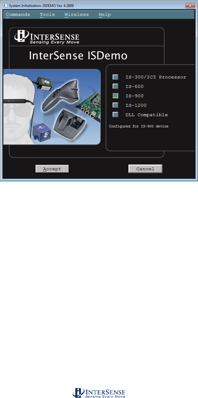
InterSense Doc. No. 072-00105-0I07 Rev. 4.2
IS-900 User Guide Page 105 of 177
Select IS-900 Series interface and click Accept to begin. Use the Detect option from this
first screen to detect serial communication port and baud rate parameters only if you
have trouble setting them manually.
The DLL Compatible interface can be used for all InterSense trackers when isense.dll is
installed in the \WINDOWS\SYSTEM32 directory of a Windows PC. For set-up and
configuration of the IS-900, it is recommended to use the IS-900 Series interface, as
some of the interactive controls through the isense.dll interface are inactive in ISDEMO.
However, the DLL Compatible option can be useful to test that the IS-900 system is
properly interfacing to the isense.dll for verification of an end-user application.
Note: You must select either IS-900 or DLL Compatible (if the isense.dll is installed), or
ISDEMO will not be able to correctly configure your tracker.
If you have an InterSense RF analyzer accessory, you can launch the user interface
from this first screen by selecting Wireless→RF Scope on the menu bar. See section
10.8 for details.
ISDEMO: Main window
This top of the main window is used to display tracking status information for all stations.
G = Genlock indicator. It appears in the right lower corner of the display if GENLOCK
feature is on and working properly. If the “G” is replaced with an “X”, this indicates the
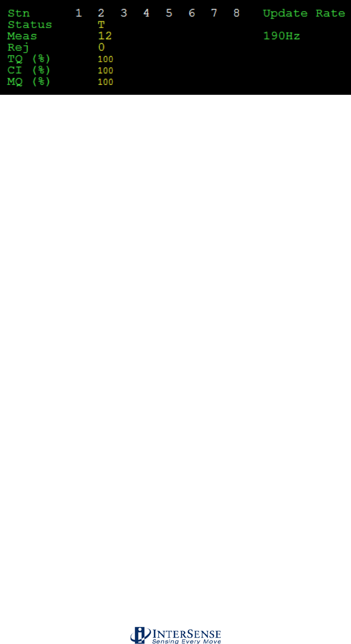
InterSense Doc. No. 072-00105-0I07 Rev. 4.2
IS-900 User Guide Page 106 of 177
GENLOCK feature in on, but a valid signal is not being detected. See Appendix F for details
about GENLOCK.
Row 1 (Stn) lists station numbers.
Row 2 (Status) displays the tracking status. Stations display T when tracking position, and
L (Lost) when position tracking is not possible. If a station configuration is invalid or
hardware is not connected, X is displayed.
Row 3 (Meas) displays the number of range measurements received by each station during
the last cycle. A range measurement is defined as an ultrasonic signal received by a single
microphone. Typical values are in the 10-14 range; low values can have several causes,
including weak microphones, low emitter volume, being too far away from the emitter, or
having the microphones turned away from the majority of emitters.
Row 4 (Rej) displays the number or range measurements rejected by the system. This
number should normally be 0-1. Measurements can be rejected for one of the following
reasons:
o SoniStrip configuration (Constellation) is inaccurate
o Certain positions or orientations may cause errors in measurements to specific emitters;
moving the tracker slightly may prevent the rejections
o Extremely fast movements can sometimes cause some measurements to be rejected
o It is worth noting that rejections are not used by the IS-900 in calculating position
updates, so are not necessarily an indication of any problem as long as the overall
measurement counts are good
Row 5 (TQ) displays the tracking quality of the station as a percentage. It is a measure of
the number of measurements a station receives and the size of the range errors of the
measurements. 100% means that the station is tracking perfectly and 0% means it is lost.
Row 6 (CI) displays the communication integrity of the station as a percentage. 100%
means that the station is communicating perfectly and 0% means that it is not
communicating at all. An “X” will be displayed on the Status line when this value drops
below 30%.
Row 7 (MQ) displays the measurement quality of the station as a percentage. 100% means
that the station has range errors of 1mm or less on average, and for a properly sighted
constellation this should be >95% for a stationary tracker, in most cases.
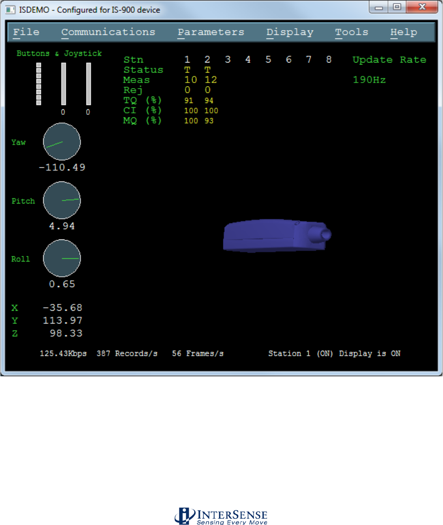
InterSense Doc. No. 072-00105-0I07 Rev. 4.2
IS-900 User Guide Page 107 of 177
ISDEMO also has six primary menus in its main window:
• File
• Communications
• Parameters
• Display
• Tools
• Help
The following sections will walk you through all of the menu options.
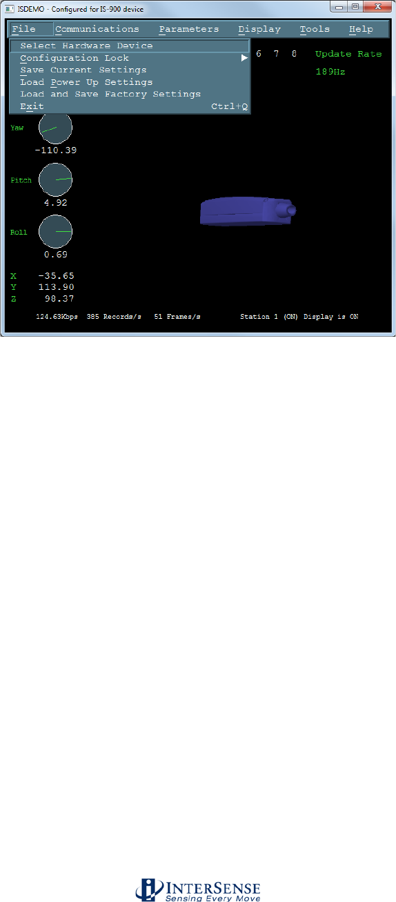
InterSense Doc. No. 072-00105-0I07 Rev. 4.2
IS-900 User Guide Page 108 of 177
10.2. File Options
The File menu (shown above) provides you with the following options:
Select Hardware Device System Initialization window (also seen at initial start-up) is
shown when Select Hardware Device is selected. Use this
window to select or detect the tracker model connected to your
computer.
Configuration Lock Configuration lock commands are used to prevent
unintentional changes to tracker configurations being saved to
permanent memory. They disable of enable the ^K command
and the W command.
Save Current Settings Sends ^K command to the tracker. This saves the current
settings to nonvolatile memory in the tracker base unit. The
next time the tracker is turned on these settings will be
restored.
Load Power Up Settings Sends ^Y commands to the tracker. This restores the
firmware to the power up condition. All changes made to the
settings since power up or last ^K command are lost.
Load and Save Factory Settings
Sends W command to the tracker. This restores the system
settings to the factory defaults.
Exit Closes ISDEMO
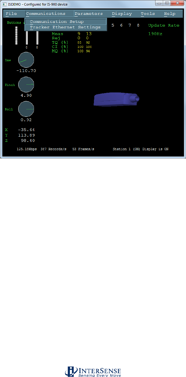
InterSense Doc. No. 072-00105-0I07 Rev. 4.2
IS-900 User Guide Page 109 of 177
10.3. Communications Options
This menu allows the communications port and the baud rate of the computer ISDEMO
is running on to be set to match the settings of the tracker. The default settings are
COM1, with a rate of 115,200 baud.
Communications Setup The IS-900 allows both Serial communications as well as
Ethernet communications. The Ethernet interface is used as a
command interface with exactly the same InterSense
command protocol used for the serial port. Either
communications interface is available as a view port while the
host application is communicating through the other interface.
Using ISDEMO on one port while communicating tracking data
through the second allows performance of basic diagnostics or
system configuration while the host application is live.
Selecting the Communication Setup menu option brings up of
the following configuration window.
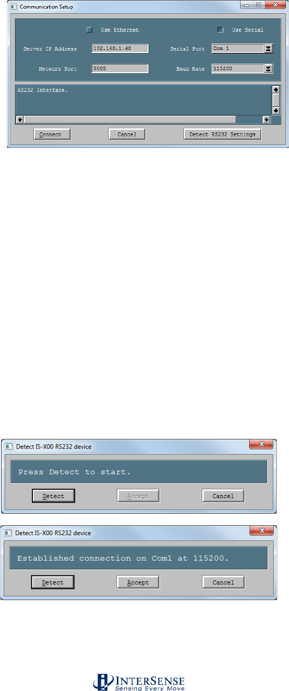
InterSense Doc. No. 072-00105-0I07 Rev. 4.2
IS-900 User Guide Page 110 of 177
Serial Configuration
Default settings are for the serial port set to COM1 with a baud rate of 115,200.
Serial Port Choose the RS232 port the tracker is connected to.
Baud Rate Choose the communications speed the tracker is set to.
Connect ISDEMO attempts to connect to the IS-900 Processor using
the selected communication parameters.
Cancel Exits the screen saving the current selected communication
parameters.
Detect RS232 Settings When chosen, this option will automatically detect the port and
the baud rate being used. The program attempts to establish
communication by sending the S command (status record
request) and waiting for a response for 1 second. If the status
record is not received within that time the program tries again
with the different communication parameters.
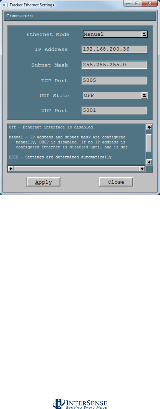
InterSense Doc. No. 072-00105-0I07 Rev. 4.2
IS-900 User Guide Page 111 of 177
Ethernet Configuration
Ethernet is supported with IS-900 firmware version 4.20 and higher. Ethernet is disabled
by default. An IP address must be configured using the serial port or LCD menu to
enable Ethernet communication. Refer to Section 4.2 to set an IP address for your IS-
900 tracker. Two Ethernet interface paths are available - a command interface (single
client, bi-directional) and a UDP broadcast interface (multiple clients, receive only). The
TCP port defaults to 5005, but is configurable.
Ethernet Modes Off – Ethernet interface is disabled
Manual - IP address and Subnet Mask are configured
manually, DHCP is disabled. If no IP address is configured
Ethernet is disabled until one is set.
DHCP - IP address and subnet mask are automatically obtained
from a DHCP server.
Server IP Address Enter the IP address of the IS-900 in the Server IP Address
box, and leave the Network Port set at 5005.
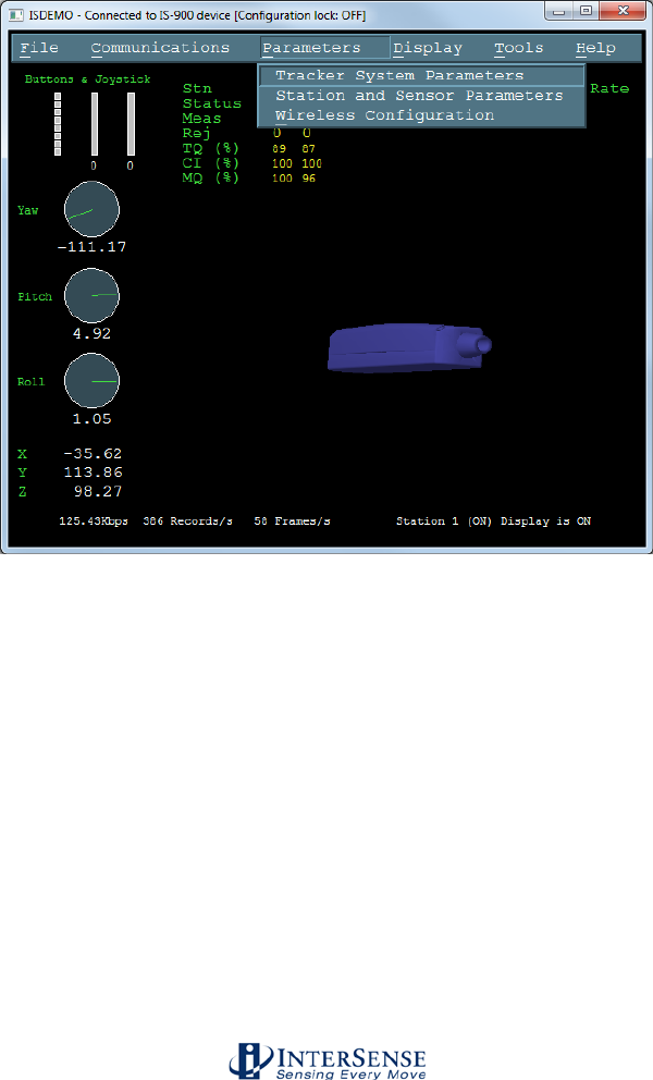
InterSense Doc. No. 072-00105-0I07 Rev. 4.2
IS-900 User Guide Page 112 of 177
Network Port The TCP port (defaults to 5005).
UDP Broadcast State ON/OFF
UDP Port Default is 5001, the Isense.DLL automatically checks ports
5001-5005. You can set the port from 1001 to 6535.
10.4. Parameter Options
Parameters menu allows access to the tracker configuration controls.
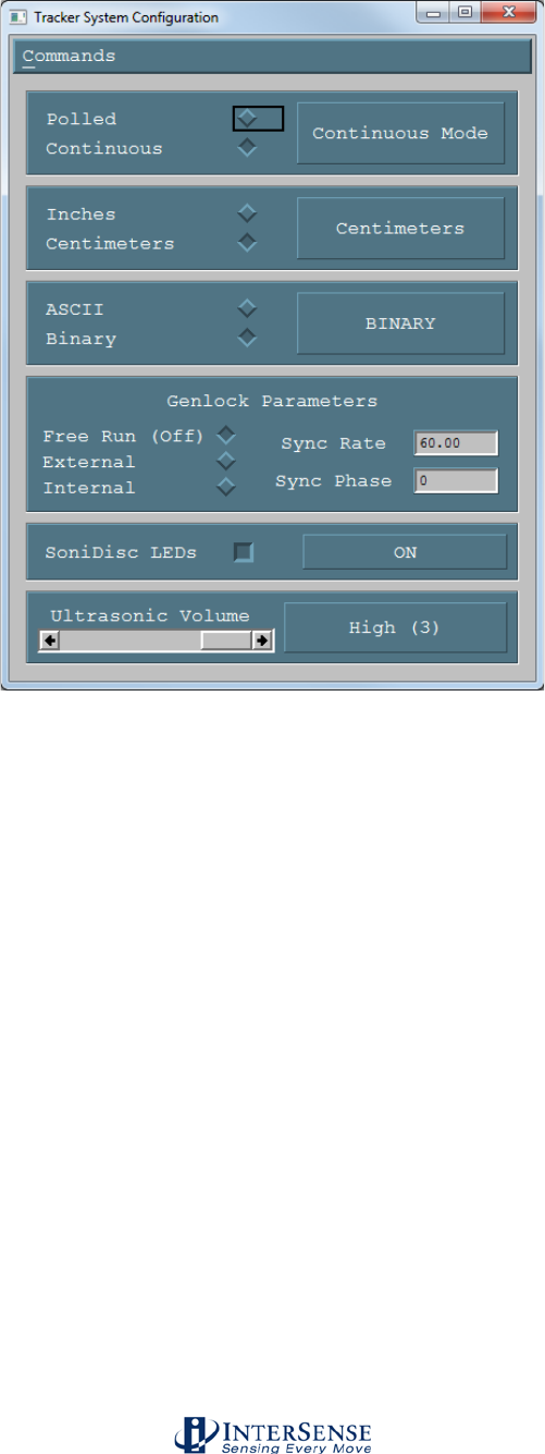
InterSense Doc. No. 072-00105-0I07 Rev. 4.2
IS-900 User Guide Page 113 of 177
Tracker System Parameters
Output Mode Polled or Continuous. In Polled mode, data records are sent
out only in response to a P command.
Measurement (output record)
Inches
Centimeters
Data Format ASCII
(F command) Numbers are returned in ASCII format. Each
number has 7 ASCII characters: a sign, 3 digits, a decimal
point, and 2 more digits.
Binary
(f command) Floats are sent as 4 byte IEEE 32-bit floats.
This can increase data throughput by minimizing the size of
the records.
Genlock State
(MG command) Off, Automatic (not supported), External
(manual, supply strobe rate), Internal (supply output record
rate).
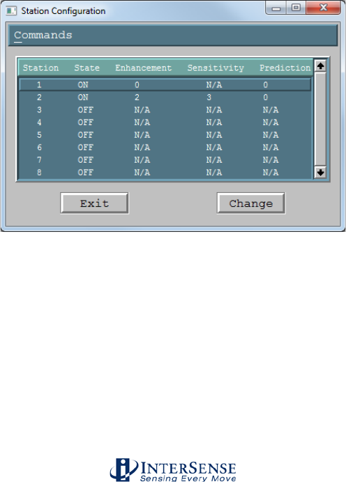
InterSense Doc. No. 072-00105-0I07 Rev. 4.2
IS-900 User Guide Page 114 of 177
Sync Rate
Value in Hertz used with Genlock enabled.
Sync Phase
0-100%.
Please see section 11 for complete details.
SoniDisc LEDs (ML command) Enable and disable the SoniStrip LEDs.
Ultrasonic Volume Sets the volume of the SoniDiscs (ultrasonic emitters).
Ranges between 0 (off) and 3 (maximum volume). Volume
levels 2 and 3 are identical unless using a power booster, in
which case volume 3 will be louder.
Station and Sensor Parameters
The window shown below lists each station to be configured. A “Station” is a position
and/or orientation-sensing unit, such as a MicroTrax head tracker. IS-900 Series
trackers can support up to 7 stations (the remaining port being reserved for SoniStrips).
Before data is displayed in this list, ISDEMO attempts to receive the configuration data
from the tracker. If this fails for any reason, an error message is displayed and data in
the list may not be reliable.
Double clicking on the Station line or selecting the Change button will bring up the
Station Configuration window where changes can be made.
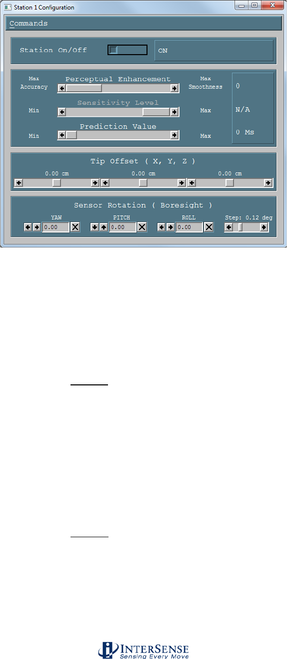
InterSense Doc. No. 072-00105-0I07 Rev. 4.2
IS-900 User Guide Page 115 of 177
Station Configuration window
Station ON/OFF When a station is ON, data records will be sent for it, even if
there is no hardware connected to the IS-900.
Perceptual Enhancement Level
In order to provide the best performance for a large range of
applications, three levels of perceptual enhancement are
available. None of the modes introduce any additional latency.
Mode 0 provides the best accuracy. The inertial tracker uses
gyros to measure angular rotation rates for computing the
sensor’s orientation. To compensate for the drift, tracker uses
accelerometers and an ultrasonic range measurement system
to measure the actual physical position and orientation of the
sensor. That data is then used to compute the necessary
correction. In Mode 0 correction adjustments are made
immediately, no jitter reduction algorithms are used. This
results in most accurate output (not recommended for head
tracking) with lowest RMS error. Use this mode for accuracy
testing or for any application that requires best accuracy.
Mode 1 provides accuracy similar to that of mode 0, with the
addition of a jitter reduction algorithm. This algorithm reduces
the accuracy by only a small amount and does not add any
latency to the measurements. Mode 1 is recommended for
augmented reality applications (i.e. overlaying or mixing both
virtual and real objects in a visualization system.)

InterSense Doc. No. 072-00105-0I07 Rev. 4.2
IS-900 User Guide Page 116 of 177
Mode 2 is recommended for use with HMD or other immersive
applications. Drift correction adjustments are made smoothly
and only while the sensor is moving, so as to be transparent to
the user.
Sensitivity Level This setting is only used when Perceptual Enhancement Level
is set to 2. It controls the minimum angular rotation rate
picked up by the MicroTrax inertial components. Default is
level 3. Increasing sensitivity does not increase latency during
normal movements. It may result in some small residual
movements for a couple of seconds after the sensor has
stopped. If your application requires sensitivity greater than
the maximum provided by this control, you must use
Perceptual Enhancement level 0 or 1 instead.
Prediction Value IS-900 can predict motion up to 50 ms into the future, which
compensates for graphics rendering delays and further
contributes to eliminating simulator lag.
Tip Offset Defines a set of position offsets, so a different point can be
tracked. Offsets are measured in the body coordinate frame of
the MicroTrax station and are entered in centimeters.
Sensor Rotation Sets boresight reference angles in degrees for the specified
station.
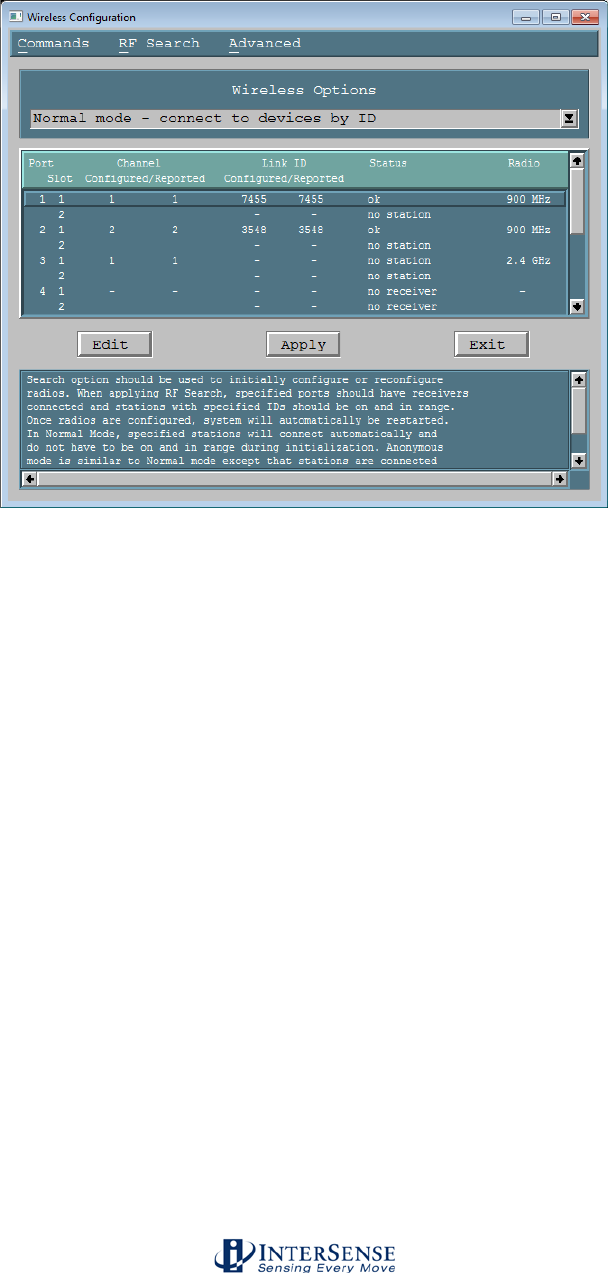
InterSense Doc. No. 072-00105-0I07 Rev. 4.2
IS-900 User Guide Page 117 of 177
10.4.1. Wireless Configuration window
The window below lists the wireless status and configuration for each processor port.
Normal Mode Determines wireless communication by device Link IDs
Anonymous Mode Determines wireless communication by wireless channel, and ignores
Link IDs
Port Port of the IS-900 Processor.
Configured Channel The channel that the connected Base Receiver Module is configured to.
No two Base Receiver Modules can be configured to the same channel /
band pair (however, the same channel is permitted if using a 900 MHz
and 2.4 GHz receiver, since each channel represents a different
frequency).
Reported Channel The channel that the connected Base Receiver Module is currently
configured for (0-15 for 2.4 GHz, 1-10 for 900 MHz).
Configured Link ID The link ID that is assigned to the receiver. Each wireless tracker has a
link ID associated with it when it is shipped, based on the lower 5 digits
of the internal device serial number. This 4-5 digit number can be found
on a label on your tracker (or its cable for trackers with cables).
Reported Link ID The link ID that is currently associated to the Base Receiver Module.
Status Port status. Any ports with a status of “no receiver” did not have a Base
Receiver Module detected, and cannot be configured.
Radio 900 MHz or 2.4 GHz band; both may be used simultaneously.
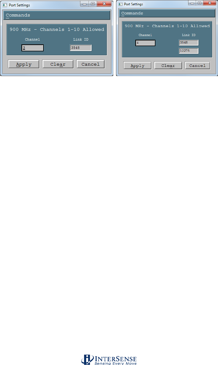
InterSense Doc. No. 072-00105-0I07 Rev. 4.2
IS-900 User Guide Page 118 of 177
Normal Mode
Use normal mode to set radios to desired channels and station IDs. Only stations with the
specified IDs are connected to. Select a port with a Base Receiver Module connected and click
Edit, or double-click on the line. The second screenshot depicts channel-sharing mode with two
Link IDs, and is only available on 900 MHz Base Receiver Modules/Trackers.
In the Port Settings dialog box, enter the channel (0-15 for 2.4 GHz radios, 1-10 for 900 MHz
radios) and station ID to use for that port. Each port must be assigned its own channel within a
given band. To maximize performance, it is recommended that active channels be separated by
one unused channel. It is possible to use adjacent channels, but interference may occur under
some circumstances.
The link ID is the 4-5 digit number on a label affixed to the exterior or cable of each tracked
device. If the ID cannot be read from the label, run a level 3 self-test or choose RF
Search→Enumerate Wireless Devices to determine the ID (see section 10.6).
Click Clear to remove settings from a port. Click Apply to dismiss the dialog box. Repeat as
needed to configure additional ports.
When done, click Apply configure radios. The operation may take about a minute to complete. If
successful, status for each configured port should be “ok.” If the status is “station not found,”
verify that link IDs are correct and devices are on and in range. Select Search→RF Search to
reapply configuration.
Once configured, stations will connect automatically and do not have to be powered on nor within
range during system initialization.
Anonymous Mode
In anonymous mode, stations are connected to if they are on the same channel as a receiver
regardless of their ID. This allows a station to be swapped out with another station set to the
same channel without reconfiguration (however a system reset via hardware switch or ISDEMO is
required, as device calibration information is only read once, during startup).
It is recommended that normal mode be used in most situations. This is especially true if the IS-
900 is operating in the vicinity of wireless InertiaCubes or other IS-900 systems with wireless
MicroTrax devices in use. In anonymous mode, the IS-900 may mistakenly connect to these other
nearby devices.
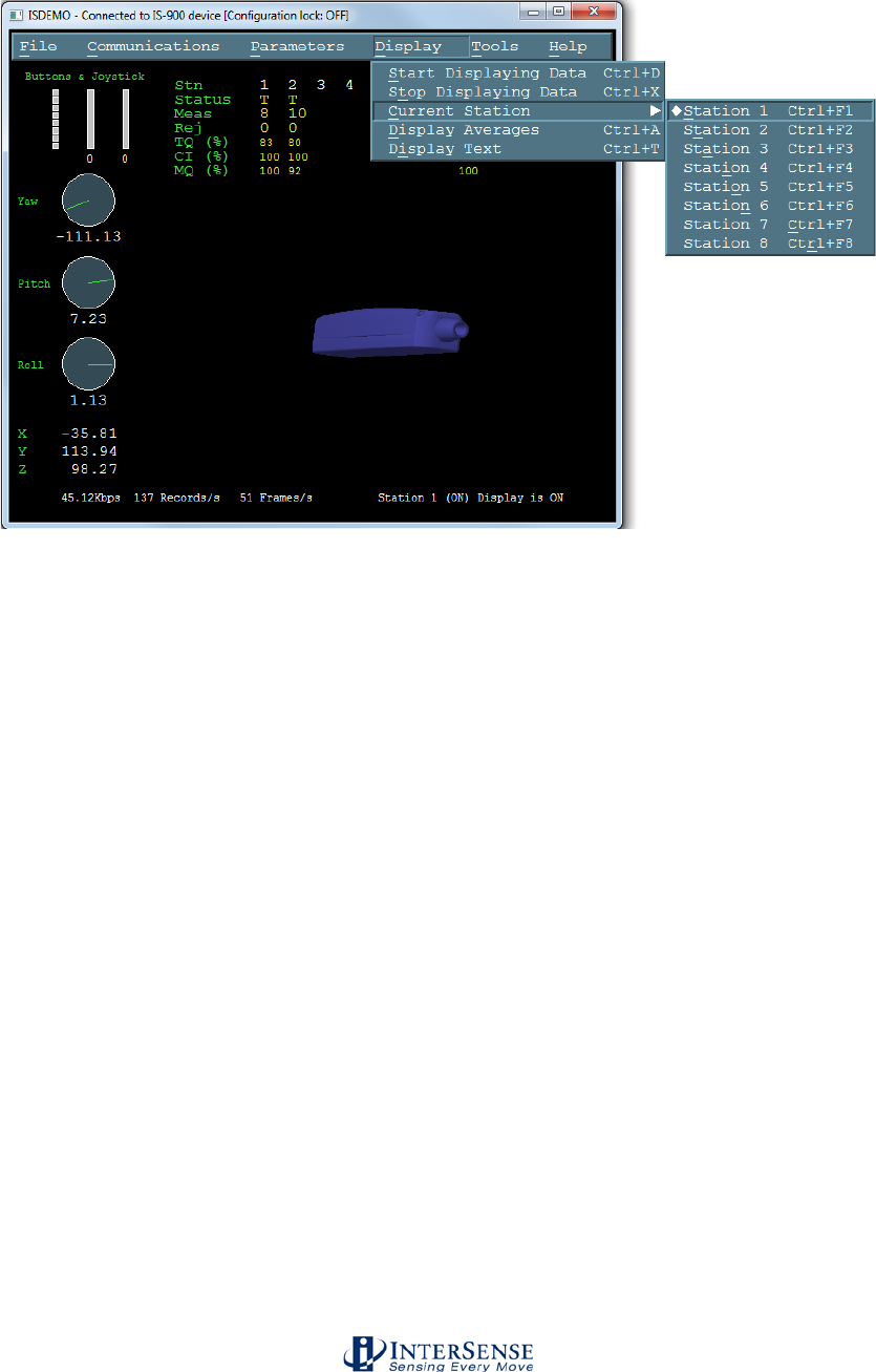
InterSense Doc. No. 072-00105-0I07 Rev. 4.2
IS-900 User Guide Page 119 of 177
10.5. Display Options
Start (and Stop) Displaying Data
To display position and orientation data being received from
the tracker, use the Start Displaying Data option in the Display
menu or press Ctrl-D. ISDEMO first attempts to establish
communication and get all configuration information necessary
to correctly interpret and display incoming data. If it fails to
receive a reply to any of the status record requests it will still
go into the display mode, but there may be no data to display
or it may not be able to display the data correctly. If such
errors are detected, stop the display by selecting Stop
Displaying Data option in the Display menu or pressing Ctrl-X
and check the connection.
Station Number Allows the user to choose which station is to be displayed in
the main window of ISDEMO. Ctrl-Fx, where x represents the
station number, can also be used to switch stations. For
example, to switch to station 2, use Ctrl-F2.
Display Text When this option is selected all status and some of the data
records are displayed in text format in the sensor display area.
To prevent graphics updates from taking over most of the
processor time, no more than 20 data records per second are
displayed.
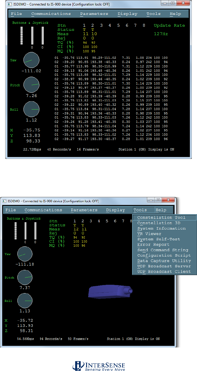
InterSense Doc. No. 072-00105-0I07 Rev. 4.2
IS-900 User Guide Page 120 of 177
Please note that whenever your tracker is in continuous mode, records are displayed in
the text window even when the display is off.
10.6. Tool Options
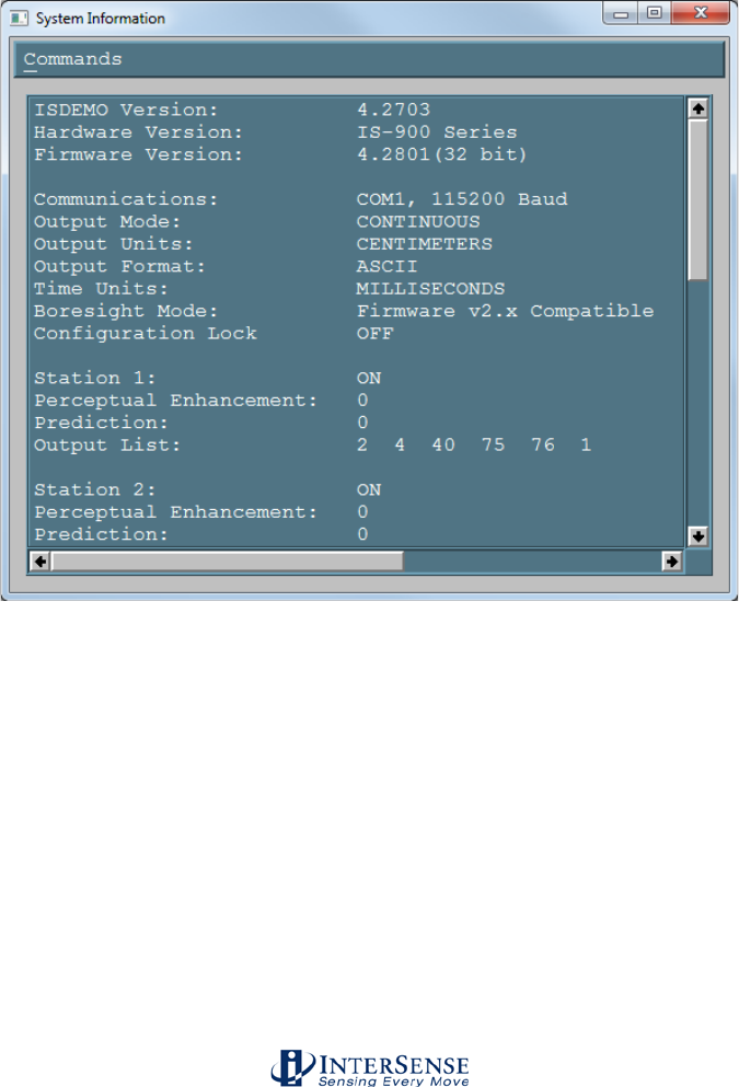
InterSense Doc. No. 072-00105-0I07 Rev. 4.2
IS-900 User Guide Page 121 of 177
Constellation™ Tool This tool provides a graphical representation of the tracked
area. All tracked devices are shown. The Constellation Tool
is extremely useful when first installing the IS-900 system.
See Section 10.7 of the manual for more information.
Constellation™ 3D This tool provides a rotatable 3D view of the current
constellation, including normal vectors. It also contains the
performance evaluator tool, and is very useful during initial
configuration of the IS-900.
System Information This window provides a summary of the InterSense tracker
system configuration.
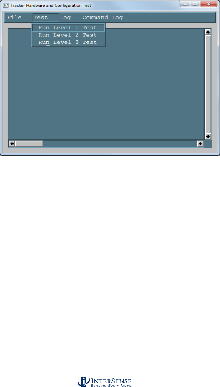
InterSense Doc. No. 072-00105-0I07 Rev. 4.2
IS-900 User Guide Page 122 of 177
System Self-Test There are three levels of tests supported for this release.
Level 1 Designed to detect and display information on all the
connected hardware and compare it to the user configuration
to evaluate it for errors. This tool is designed for
troubleshooting the system when hardware failure is
suspected.
Level 2 Displays the current Communication status, Tracking quality
and URM noise for all active stations. Communications
Status for wired stations should always show 100%. If a
station is disconnected, it shows 0%. Anything in between
might indicate a poor connection or an excessive length of
cable. Wireless stations, on the other hand, typically show
less than 100% because some records are lost or corrupted
due to the nature of the radio link. Tracking quality is a
measure of the number of measurements a station receives
and the size of the range errors of the measurements. 100%
means that the station is tracking perfectly and 0% means it is
lost. URM noise is measured by suspending the firing of
beacons for a period of time and counting the number of
detections at each microphone. Under good conditions, the
percentages should be 0% or close to it for all microphones.
IMU stands for Inertial Measurement Unit, also called
InertiaCube. URS stands for Ultrasonic Ranging System and
includes interface board, microphones, and transmitters
(SoniDiscs).
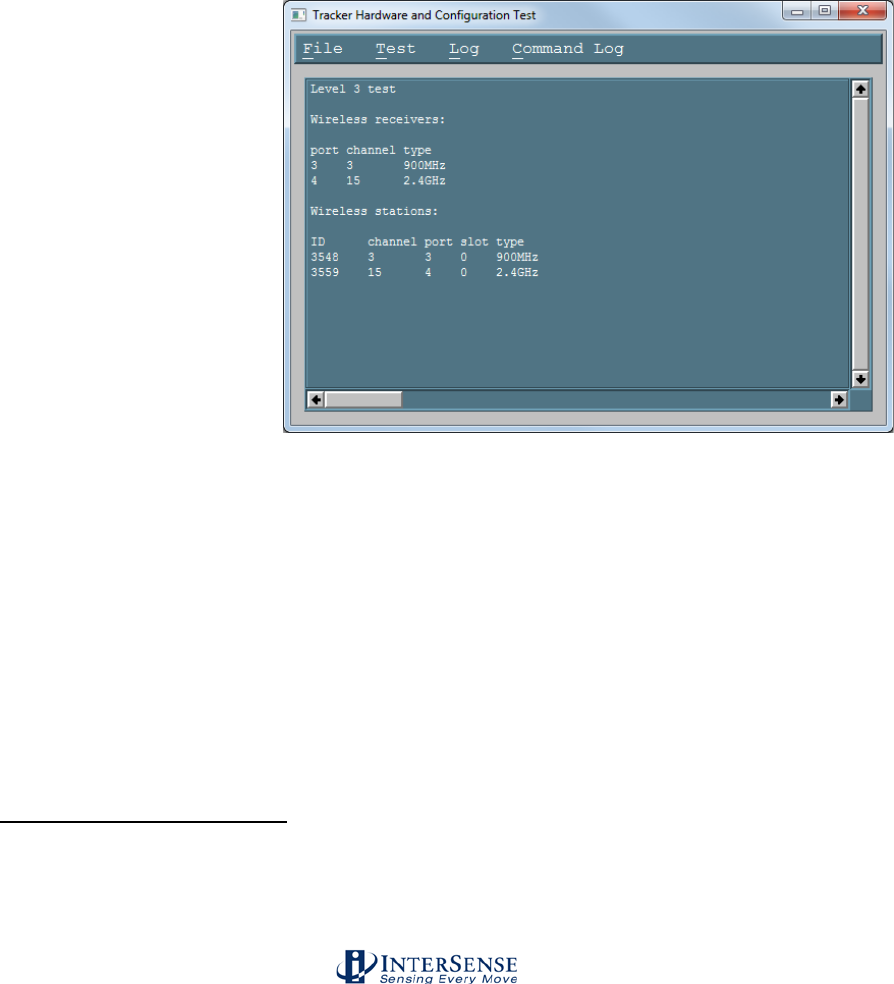
InterSense Doc. No. 072-00105-0I07 Rev. 4.2
IS-900 User Guide Page 123 of 177
Level 3 Level 3 Searches for wireless stations and displays
wireless receiver and station configuration. Please note that
the search operation can take a minute or so to complete. This
tool is useful for identifying a wireless device if its ID is
unknown. The ID is needed to use the ISDEMO Wireless
Configuration Tool. Wireless receivers are listed with their
respective port numbers and channel settings plus a field that
indicates the type of control (active or manual).
MicroTrax receivers have active control, which means channel
settings and station pairings can be changed using the
Wireless Configuration Tool. Previous-generation receivers
have manual control via a mechanical channel switch.
Wireless stations that were detected during the search are
listed with their respective IDs and channel settings.
If the station is paired with a receiver, its port and slot number
is also shown. The search operation can only detect stations
that are powered on and in range. Since the search operation
scans through all available channels, be aware that it may
temporarily interfere with other InterSense trackers if they are
in range. Any stations reporting the ID 65535 indicate a
communication failure between the radio and the device
connected to it (such as between the head tracker and lapel
transmitter, or the wand and its internal radio board).
Self test reports generated here can be saved to the disk using the Save to a File option in
the File menu. You may send the reports to InterSense technical support
(techsupport@intersense.com) for analysis and help with troubleshooting.
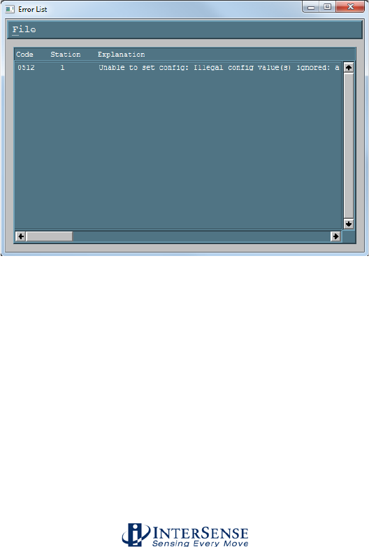
InterSense Doc. No. 072-00105-0I07 Rev. 4.2
IS-900 User Guide Page 124 of 177
The self-test procedures may generate warning and errors that are displayed at the end of
the report. If errors are detected, corresponding error records are also generated and can
be displayed in the Error Report tool.
Log The system log file can be retrieved and viewed with the
Log→Get System Log File option on the System Self Test
screen.
Command Log Creating a command log can be enabled with Command
Log→Command Logging. A previous command log can be
viewed with Command Log→Get Command Log File.
The command logging function can also accessed from this
screen with the Log→Command Log menu.
Error Report System errors are logged by the tracker and displayed on the
base unit LCD. If software error reporting is enabled, error
messages are sent out the serial port and can be displayed by
ISDEMO. This tool is designed to display InterSense-specific
error messages and ignores standard Fastrak errors.
See Section 0 for a list of errors and their meanings.
File
Save to File Ctrl+S
Save contents of the window to a text file.
Get From Tracker F5
Requests full list of currently stored error codes and displays it.
Clear All Lists Sends command to the tracker to clear the error list and
erases the contents of the window.
Exit Ctrl+Q
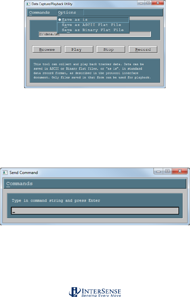
InterSense Doc. No. 072-00105-0I07 Rev. 4.2
IS-900 User Guide Page 125 of 177
Data Capture/Playback Utility
ISDEMO has the ability to write the data it receives from the
tracker to a file. To utilize this feature you must first specify
the name and location of the output file. To start data
collection, select Record. Data can be Saved as is, or in an
ASCII or Binary Flat File. When the Flat File option is
selected, only tracker data is saved, one line per update cycle.
To import data to Excel or Matlab the output format must be
set to ASCII or the ASCII Flat File option must be used.
Previously recorded data can be displayed through ISDEMO
by selecting Play. Playback option will only work on files
saved with the Save as is option.
Send Command String Allows single line commands to be sent to the tracker. This
tool is provided to allow control over the tracker parameters
not supported in the ISDEMO menus and dialogs or on the
LCD button panel. For instance, this function can be used for
test and debug purposes. Type in the command and press
Enter or Return. The <CR LF> pair is automatically added to
the end of the line before it is written to the serial port. See
Section 4 - Interface Communication Protocol, for the
complete list of all available commands.
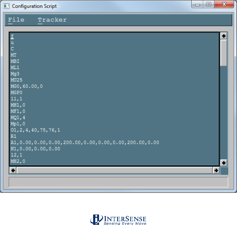
InterSense Doc. No. 072-00105-0I07 Rev. 4.2
IS-900 User Guide Page 126 of 177
Configuration Script Tool This utility provides complete control over the tracker
parameters, including support for multiple configurations.
Contents of the display area of the window can be edited
directly, like in any text editor.
File
Load from File Ctrl+O
Opens a file selection dialog box. Configuration file must be a
plain text file.
Save to a File Ctrl+S
Used to save the contents of the window to a text file.
Exit Ctrl+Q
Tracker
Retrieve from Tracker F5
Queries the tracker for all standard configuration parameters,
converts them to commands and displays the results in the
window. This can then be saved to a file. This is a superset of
the data saved by the Constellation™ Tool.
Send to Tracker
Sends all interface commands in the display area to the
tracker. CR LF pair is automatically added to each line.

InterSense Doc. No. 072-00105-0I07 Rev. 4.2
IS-900 User Guide Page 127 of 177
System Errors
Some basic system errors and their meanings are listed in the table below. This is a partial list
and does not contain all possible error codes; please contact InterSense for more information on
specific error codes.
Code
Type
Message
Comments
6401
General
Math exception
Invalid sensor data or bad IMU
calibration - if persists contact
InterSense.
6402
General
SOS out of range - check PSE
configuration
Poor/invalid Constellation or
microphone configuration.
6404
General
Inconsistent PSE position or
obtuse PSE angle
Check beacon normal vectors.
6408
General
File I/O error
Contact InterSense.
6409
General
Ethernet error
Contact InterSense.
010x
URS
URM start/read failed
Likely communication error.
020x
IMU
IMU start/read failed
IMU read timed out
Likely communication error.
0205
IMU
IMU NVRAM read failed
Failure while reading calibration data
from MicroTrax device EPROM,
contact InterSense if issue persists.
020A
IMU
No MicroTrax device connected
to this port
Contact InterSense if issue persists.
020B
IMU
Failed reading sensor EPROM
Contact InterSense if issue persists.
020C
IMU
IMU get config failed
Driver level error. Occurs during IO
Board initialization.
020D
IMU
Can't select IMU channels
IMU read error.
030A
Wireless
Link ID for stations are both…
Duplicate station ID encountered.
030B
Wireless
Channels for stations are
both...
Stations are set to same channel.
030C
Wireless
Mixed radio types not
supported
Older (MiniTrax) radio sets cannot be
used in combination with MicroTrax.
040x
I/O Card
No I/O card found or error
Contact InterSense.
0501
Config
Alignment reference frame
Invalid alignment reference frame
0504
Config
SoniDisc Hardware ID out of
range
SoniDisc hardware ID is invalid.
0510
Config
Too few SoniDiscs to track
Minimum of 3 SoniDisks required.
060x
Joystick
Joystick start/read failed
Joystick get info failed
Likely communication error.
Standard Fastrak
error codes
1 Field missing, command is invalid.
2 Parameter is not a numeric value, command is invalid.
3 Parameter value is out of range, command is invalid.
4 Not configured (not used by InterSense).
5 Buffer limit exceeded (not used by InterSense).
99 Invalid command parameter.
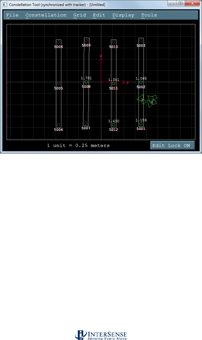
InterSense Doc. No. 072-00105-0I07 Rev. 4.2
IS-900 User Guide Page 128 of 177
10.7. Constellation™ Configuration Tool
Constellation™ Tool is used to configure and manage the Constellation™ of SoniDiscs.
This is the most important part of tracker configuration, as it has a direct effect on quality
of tracking.
Terminology
IS-900 models contain an ultrasonic subsystem that includes SoniDiscs (Ultrasonic
Transponder Beacons) and Microphones (URMs). To generalize the interface protocol
and configuration tools for these tracker models, InterSense uses the term: PSE -
Position Sensing Element.
A PSE may be Mobile or Fixed. Mobile PSEs are assigned to the stations and their
movements are tracked by the system. Fixed PSEs form a Constellation that is used
as a reference for tracking. In the case of IS-900 tracking systems, microphones are
mobile PSEs and SoniDiscs are fixed PSEs.
General Guidelines
The position of a SoniDisc is defined as the coordinates of the center of the grill covering
the speaker. All values are entered in meters. The coordinates of the SoniDiscs are
entered in a user-defined, locally leveled coordinate frame. The coordinate system is
right-handed with X pointing forward, Y to the right and Z pointing down (see Section

InterSense Doc. No. 072-00105-0I07 Rev. 4.2
IS-900 User Guide Page 129 of 177
3.1 for details on the InterSense standard coordinate system). Position data for all
stations is computed relative to that coordinate system.
Mobile PSE configuration is stored in the EPROM of each station and is configured
automatically without user input. The Constellation, however, is custom for each
installation and must be configured before the system can be used.
SoniDiscs are available in several types of protective housings, including SoniPods,
SoniFrames, SoniWings, and SoniStrips. This Section will focus on the most common
form—SoniStrips. For more information about the other SoniDisc housing styles, see
their appropriate supplemental manual. For best performance it is generally
recommended that SoniStrips be installed in a regular grid over the tracked area. The
total distance from a SoniDisc in the Constellation to a tracked station should not
exceed 3.0 meter (10 feet) to guarantee good signal detection (4.0 meter with +15 VDC
external power boosters).
IS-900 default configuration does not contain a Constellation, so it is up to the user to
configure it. The system is shipped with a packing list containing the part numbers of the
included SoniStrips. These part numbers and corresponding SoniDisc Hardware IDs are
used in the Constellation tool to identify the SoniStrips.
To operate, the system needs to know the position and orientation of each of the
SoniDiscs in the Constellation with high degree of accuracy (2 to 3 mm positional
accuracy and approximately 5 degrees for the normal vectors of each SoniDisc in the
Constellation; the positional accuracy is far more important than the angular accuracy
for tracking purposes). A high accuracy device, like a total station (also known as a
Theodolite with absolute position measuring capabilities), is required to measure the
positions of the SoniDiscs and enter them into the system configuration. The importance
of the quality of this data can’t be overstated, as the system cannot track better than its
configuration would allow.
A unit normal vector, as shown in the figure above, defines the orientation of a SoniDisc.
The default assumption is that the Constellation is installed horizontally over the
tracked area, so the normal vector points straight down with unit normal vector
coordinates of 0,0,1 (the InterSense Z axis). Entering the correct normal vector for each
SoniStrip is important. The normal vector information is used by the IS-900 tracking
algorithm to correctly schedule the polling of SoniDiscs.
File Menu Open Opens a file selection dialog. Select a configuration file and
click OK. The file is read in and Constellation contained in it
replaces the currently displayed configuration.
Save Currently displayed Constellation is saved to a file previously
selected with the Open or Save As commands.
Save As Opens a file selection dialog. Current Constellation is
written to the selected file, previous contents are overwritten.
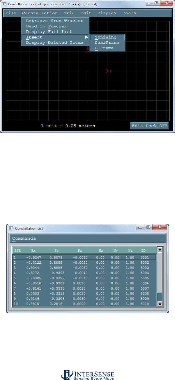
InterSense Doc. No. 072-00105-0I07 Rev. 4.2
IS-900 User Guide Page 130 of 177
Constellation Menu
Retrieve from Tracker
ISDEMO requests the current Constellation from the IS-900
base unit and displays the received configuration. Any
configuration displayed prior to this command is replaced.
Send To Tracker Currently displayed configuration is sent to the tracker. This
command is used to apply custom configuration once data
entry has been completed. Please note that Constellation
editing is done off line, so this step is required.
Display Full List
Displayed window contains the entire Constellation, one
SoniDisc per line. Selecting Change item under the Edit menu
or double-clicking on a line opens the SoniStrip Properties
window, where position and orientation data can be edited.
You can also use this window to selectively delete SoniDiscs.
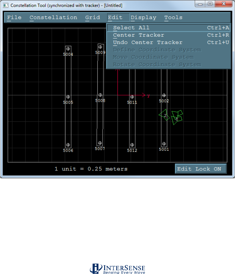
InterSense Doc. No. 072-00105-0I07 Rev. 4.2
IS-900 User Guide Page 131 of 177
Insert SoniDiscs in pre-calibrated configurations such as the
SoniWing, SoniFrame, and L-Frame can be added to the
Constellation with this feature. By selecting one of the three
choices, ISDEMO will prompt the user to enter information
about the hardware in use. After selecting the proper settings
for the hardware you intend to use, ISDEMO will add the
associated SoniDiscs to the Constellation.
Note that ISDEMO has an Edit Lock button that must be
pressed to change it from Edit Lock On to Edit Lock Off in
order to insert or move SoniStrips.
Grid Menu This feature is designed for the IS-1200 and should not be
used with the IS-900.
Edit Menu
Select All This action will select all the SoniStrips and corresponding
SoniDiscs. Use to perform additional “right mouse click”
operations on the entire SoniStrip Constellation.
Center Tracker The display origin of the Constellation, Tool is moved so that
station currently selected for display in the main window of
ISDEMO is displayed in the center of the screen.

InterSense Doc. No. 072-00105-0I07 Rev. 4.2
IS-900 User Guide Page 132 of 177
Undo Center Tracker The effects of Center Tracker command are removed and
display origin is aligned with the origin of the coordinate
system.
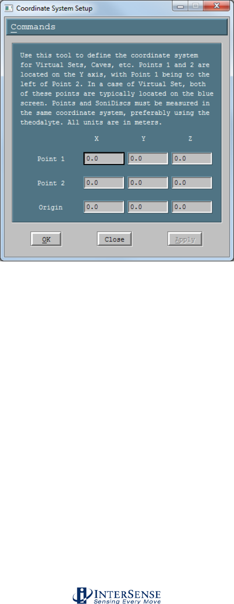
InterSense Doc. No. 072-00105-0I07 Rev. 4.2
IS-900 User Guide Page 133 of 177
Define Coordinate System
Used to specify the exact location of your origin when using a
total station to measure the exact XYZ locations of your
SoniDiscs.
Move Coordinate System
Used to move the origin of the coordinate system to a new
location. After this menu item is selected, left-click in the
display area and while holding the button down, move the
mouse. The coordinate system will then move with the
mouse. Release the mouse button when satisfied with the
location. Positions of the SoniStrips are recalculated for the
new coordinate system and redrawn. This command has the
same effect as selecting all SoniStrips and moving them to a
new location relative to the origin. To apply the changes use
Send To Tracker item in the Constellation menu.
Rotate Coordinate System
Used to rotate the coordinate system. After this menu item is
selected, left-click in the display area and while holding the
button down, move the mouse up or down. The coordinate
system will rotate in the clock-wise or counter clock-wise
direction. Release the mouse button when satisfied with the
new orientation. Positions of the SoniStrips are recalculated
for the new coordinate system. To apply the changes use
Send To Tracker item in the Constellation menu.
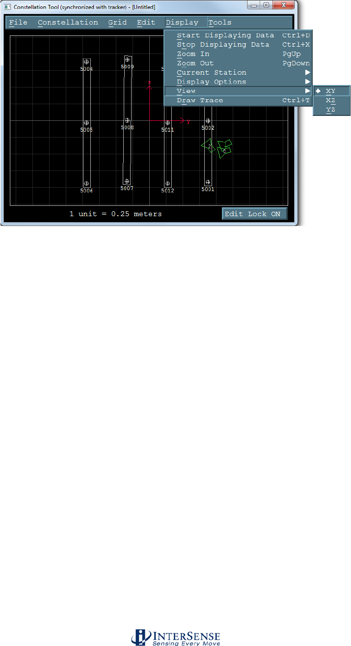
InterSense Doc. No. 072-00105-0I07 Rev. 4.2
IS-900 User Guide Page 134 of 177
Display Menu
Start Displaying Data Turns the display on. Configured stations are displayed in
green when tracking, or in red if lost. When display is on,
SoniDiscs in the Constellation are displayed in green when
they are used for tracking or in red, if range measurements
received are rejected by the tracker. During normal operation
SoniDiscs should not consistently appear red. If they do, for
different positions and orientations of the tracker, the
Constellation should be examined for configuration errors.
The IS-900 only uses the SoniDiscs in the immediate vicinity
of a station, all others are ignored and will be drawn in white.
Stop Displaying Data Turns the display off. Constellation editor commands can
only be used when display is off.
Zoom In/Out Changes the scale factor of the display. Current zoom setting
is displayed at the bottom of the screen.
Current Station Changes which station ISDEMO will show as the primary
station. Certain functions, such as Center Tracker (from the
Edit menu) will depend on which station is the current primary
station.
Display Options Hardware IDs of the SoniDiscs and ultrasonic range
measurements can optionally be displayed along with the
positions of the configured stations.
View In most cases a Constellation is installed horizontally over
the tracked area, so XY view is the default. In other cases, XZ
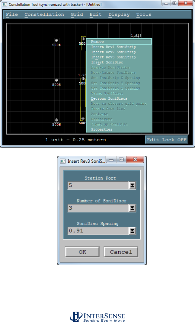
InterSense Doc. No. 072-00105-0I07 Rev. 4.2
IS-900 User Guide Page 135 of 177
and YZ views can be used. The coordinate system is right-
handed with X forward, Y to the right and Z pointing down.
Using the Constellation Graphical Interface to manually configure a
Constellation
By “right-clicking” your mouse in the constellation window, a list of options to manually
configure your Constellation appears. Use your mouse to select which SoniStrip
and/or SoniDiscs you would like to manipulate. Be sure to turn the Edit Lock button OFF
before trying to edit the Constellation.
Remove Removes selected (highlighted in yellow) SoniStrips or
SoniDiscs from the Constellation.

InterSense Doc. No. 072-00105-0I07 Rev. 4.2
IS-900 User Guide Page 136 of 177
Inserting SoniStrips 1. Right-click in the Constellation Tool window at the position
where the new SoniStrip is to be placed.
2. Select Insert Rev3 SoniStrip item. Rev1 and Rev2 SoniStrips
are not generally used with IS-900 SimTracker or VETracker
processor configurations (though InterSense does have hubs
which provide backward compatibility with existing SoniStrips).
A window listing available SoniStrip options is displayed.
Select one and click OK. The new SoniStrip will appear in the
display area. It is also removed from the list of available
SoniStrip options.
3. Using the mouse move the newly added SoniStrip to the
desired position. Note that mouse movement of SoniStrips
should only be done for initial testing; in general it is
impossible to obtain the required accuracy for proper tracking
in this manner.
Moving SoniStrips SoniStrip position and orientation can be changed using the
mouse or by using the commands available on the right-click
menu. To move with the mouse, select the SoniStrip and
drag. Multiple SoniStrips can be selected and moved by
keeping the Ctrl or Shift keys pressed while selecting and
dragging. To rotate a SoniStrip using the mouse, select one of
the SoniDiscs and without releasing the left mouse button,
move the mouse up or down. The SoniStrip will rotate about
the selected SoniDisc. If more than one SoniDisc is selected,
the whole SoniStrip is moved with the mouse.
To make exact movements, use the Constellation→Display
Full List menu, which can make precise translations to
individual SoniStrips, or the Move/Rotate SoniDiscs option
from the right-click menu.
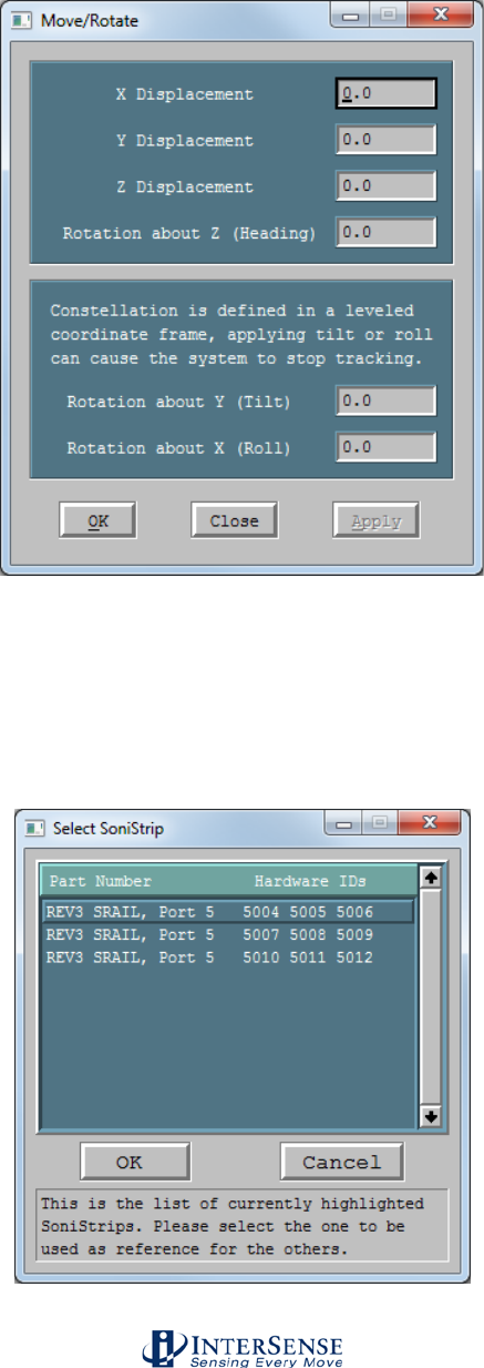
InterSense Doc. No. 072-00105-0I07 Rev. 4.2
IS-900 User Guide Page 137 of 177
Move SoniStrips (right-click menu)
Select one or more emitters first (the actual circles need to be
selected, not just the SoniStrip grouping). All values are
entered in meters. This menu allows both displacement and
rotation along/about all axes. Units are in meters.
Line-up SoniStrips (right-click menu)
This tool changes the orientation of all selected SoniStrips to
match one of them. The selection window displays a list of all
the currently selected SoniStrips. Choose one and click OK.
All selected SoniStrips become parallel. This is useful when
configuring a Constellation installed on a regular grid, such
as a drop ceiling.
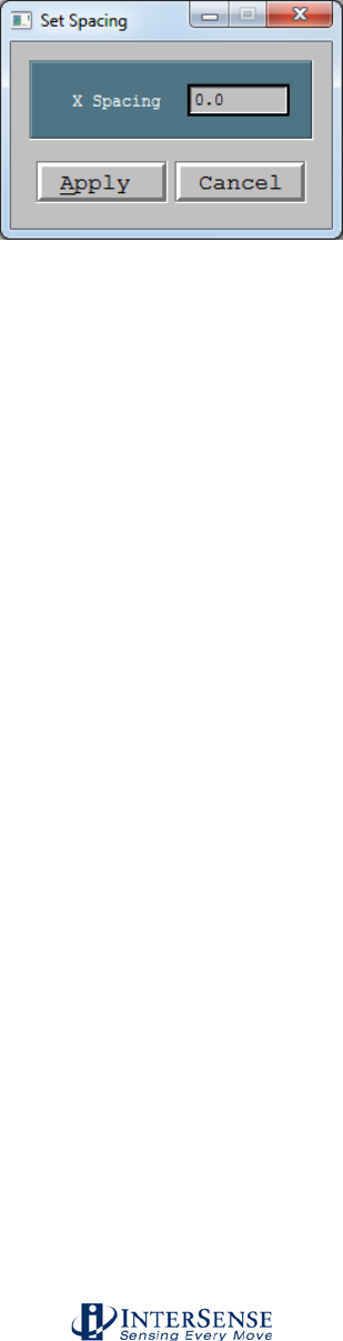
InterSense Doc. No. 072-00105-0I07 Rev. 4.2
IS-900 User Guide Page 138 of 177
Set X/Y/Z Spacing (right-click menu)
This tool applies a set spacing to the group of selected
SoniStrips. Value is entered in meters. The order of the
SoniStrips is preserved. For example, when setting up a grid
attached to a drop ceiling with 2 foot tiles, enter 0.6096 and
click Apply.
Light Up SoniDisc (right-click menu)
This option is extremely helpful in diagnosing potential cabling
and/or configuration problems. By selecting a single SoniDisc
and then choosing this option, the blue LED for the selected
SoniDisc is turned on for a few seconds. Use this visual
confirmation to check that the SoniDisc is connected properly,
and that its location in the Constellation is consistent with its
location in the physical world.
Properties A more precise way to move or rotate a SoniStrip is to use the
Properties Window, which is opened by double-clicking on a
SoniStrip or selecting Properties in the right-click menu. The
properties window lists positions and normal vectors of the 3
SoniDiscs that belong to the SoniStrip. To move or rotate a
SoniStrip, change the position values for one of the SoniDiscs.
You’ll notice that Apply button becomes active and the
Hardware IDs of the other 2 SoniDiscs are grayed out and
corresponding position fields are disabled. By clicking the
Apply button, a dialog box is displayed that allows the action
that is to be performed next to be selected. First option
(default) will move the entire SoniStrip to the new location
without changing its orientation. Alternatively, the SoniStrip
can be rotated about one of the remaining SoniDiscs. The
rotation algorithm uses the selected SoniDisc as the pivot
point and computes the line from that point to the new location
of the SoniDisc that had the position data changed. The
SoniStrip is then rotated to correspond to that line. Actions
can be cancelled at any time.
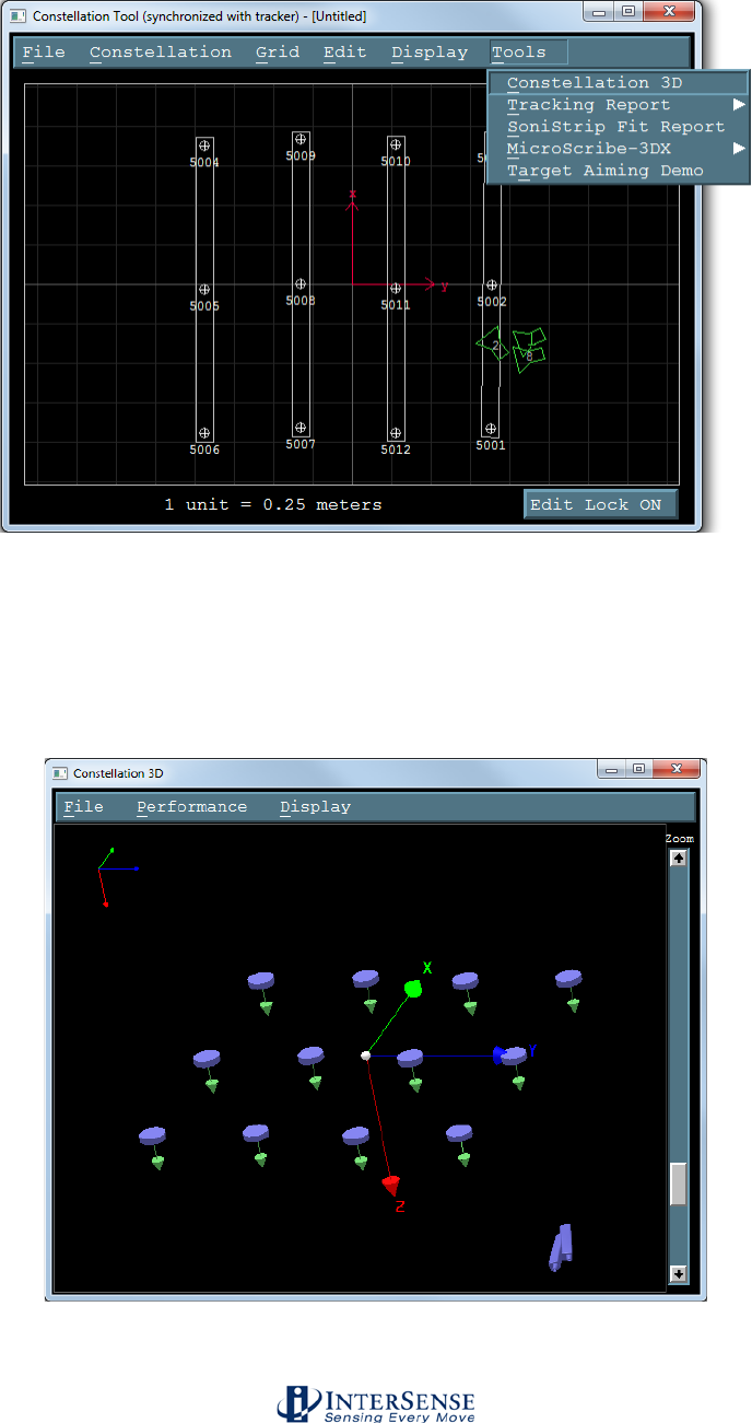
InterSense Doc. No. 072-00105-0I07 Rev. 4.2
IS-900 User Guide Page 139 of 177
Tools Menu
Constellation 3D This tool gives a three dimensional view of the constellation,
as well as all tracked devices. Each SoniDisc is drawn with a
normal vector and optional beacon ID number. Use the slide
bars or mouse to zoom in and out. Click and drag the main
view to rotate the constellation. Left click rotates, right click
drags, and scroll wheel zooms.
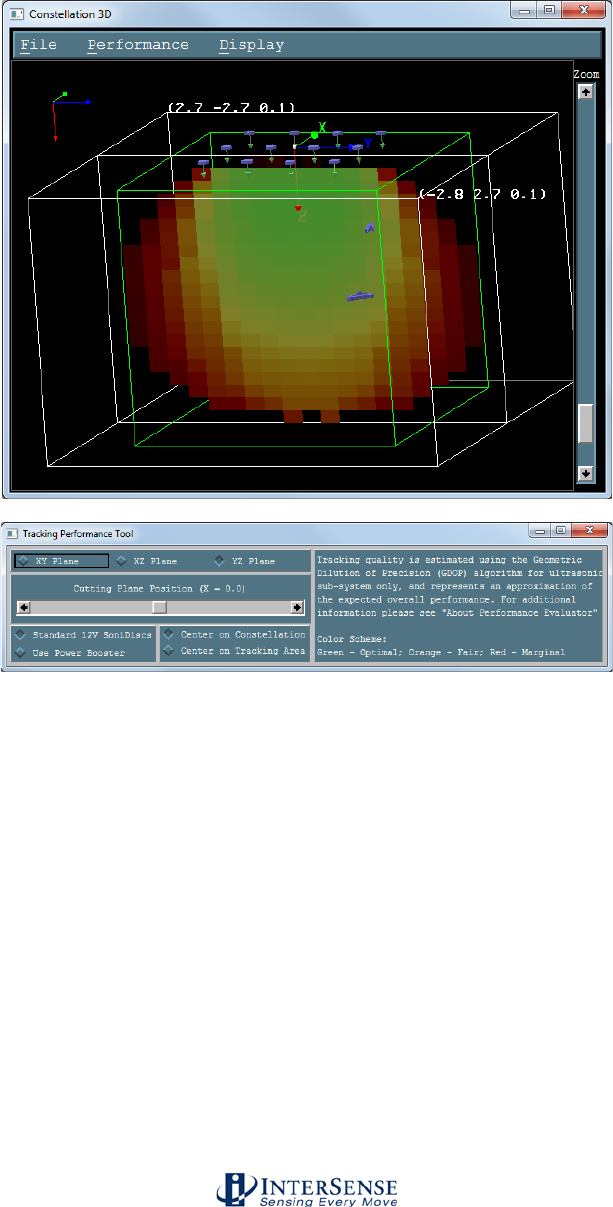
InterSense Doc. No. 072-00105-0I07 Rev. 4.2
IS-900 User Guide Page 140 of 177
The Constellation 3D tool also includes a three dimensional
performance tool. This feature will allow an end user to
estimate the ultrasonic signal strength and tracking geometry
quality under a Constellation. For more information on this
tool click on About.
Tracking Report Information is gathered about all PSEs. A history of when
stations become ‘lost’ and then reacquire is also recorded at
the bottom of the file. This report is helpful when a PSE
hardware failure is suspected. The Tracking report file can be
saved as a text file and e-mailed to InterSense technical
support for review. The Constellation must be retrieved and
Display turned on in order to record this data.
SoniStrip Fit Report Useful to estimate the overall accuracy in calibration of a
constellation file which uses SoniStrips. The positions and
distances between three SoniDiscs on one SoniStrip are
compared to SoniStrip manufacturing specifications.
Inaccuracies in the calibration of the SoniDiscs will affect the
overall accuracy of the IS-900 system.

InterSense Doc. No. 072-00105-0I07 Rev. 4.2
IS-900 User Guide Page 141 of 177
Microscribe-3DX Using a Microscribe is an extremely accurate way to measure
the positions of your SonisDiscs. First, Set up and initialize
the Microscribe. Plug the microscribe into a serial port (COM1
through COM4) of your PC. In the main window of ISDEMO,
change the communications parameters to the COM port.
Next use the right-click insert function of ISDEMO
Constellation Tool. Select a SoniDisc you would like to map
by highlighting it. Move the pointed end of the Microscribe to
be directly in front of the center of the SoniDisc you are
mapping. Use the Microscribe foot petal to record the position.
ISDEMO will move the SoniDisc to the proper location. You
will then need to configure the normal vectors of the SoniDisc
using the right-click properties feature.
Target Aiming Demo Designed to show the accuracy and repeatability of the
tracking system. When the zero point of a station is pointing at
a SoniDisc, the color will change. Targets can be added to the
constellation as phantom SoniDiscs with Station ID’s less than
100.

InterSense Doc. No. 072-00105-0I07 Rev. 4.2
IS-900 User Guide Page 142 of 177
10.8. RF Scope
RFScope usage
In order to set channels optimally, it is recommended that the RFScope utility be used to check
for wireless interference from sources such as wireless LANs and other portable devices
operating in the 900 MHz or 2.4 GHz bands supported by the IS-900 receivers. Setting trackers
to channels with significant wireless interference on them can result in poor performance, or in
extreme cases, the devices being unable to change channels back to a clear channel without
isolating both the receiver and transmitter in a shielded location. The following simple steps are
recommended each time that the IS-900 is set up in a new environment, or if the RF environment
is changed in any way, such as adding a wireless access point to the tracking area. Firmware
version 4.2601 or later is required to use this feature, along with ISDEMO 4.2703 or later (for 900
MHz support).
In order to use RFScope, you must use the RS232 connection to the IS-900, though the initial
Port Access command may be sent over Ethernet. Follow these steps:
1. Note which stations have wireless receivers connected to them (either by physically
looking at the IS-900 or as reported by the Wireless Configuration dialog in ISDEMO)
2. Select Tools > Send Command String from ISDEMO
3. Send the command MPortAccessx, where ‘x’ is the port number of the receiver you
would like to use. For most installations, it doesn’t matter which receiver is selected, but
in some cases the receivers may be arranged such that they are in different areas of the
room or even in separate rooms, in which case the RF environments may be significantly
different and testing multiple receivers may be helpful. This command is case sensitive.
4. The front LCD panel of the IS-900 should display a message indicating that it is in Port
Access Mode, and that the Enter key may be pressed to exit. Other than rebooting, the
Enter key is the only way to exit this mode. The red LED corresponding to the receiver’s
port should illuminate as well.
5. Close ISDEMO
6. Reopen ISDEMO, and select Wireless > RFScope from the main selection screen (do
not select “IS-900”.
7. Check for wireless interference as described below.
8. Once testing is complete, press “Enter” on the front panel and either reconnect with
ISDEMO and choose File > Load Power Up Settings, or simply restart the processor
using the switch on front. Your trackers will not function until the IS-900 has been
restarted by one of these two methods.
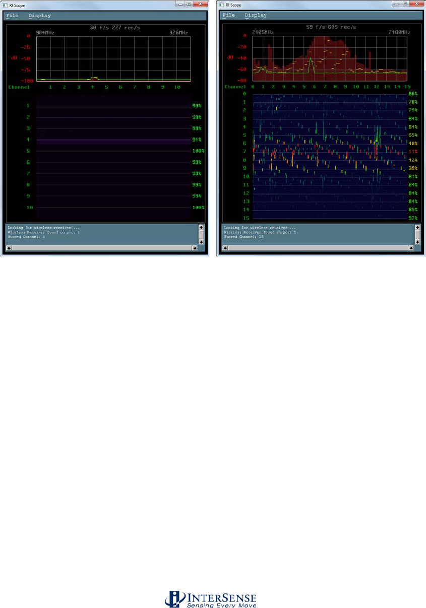
InterSense Doc. No. 072-00105-0I07 Rev. 4.2
IS-900 User Guide Page 143 of 177
The RFScope display consists of several sections. The section at the top shows the current,
peak, and moving average signal strength values in 1 MHz increments from 2405 to 2480 MHz
(or 904 to 926 MHz), as reported by the receiver. The current measurements are shown with a
green line graph, the peak signal strength is shown as a dark red bar graph, and the moving
average lines are shown as yellow lines that gradually decrease in strength. Screenshots below
show 900 MHz (left) and 2.4 GHz (right) spectrum displays.
The lower section is a sideways-scrolling “waterfall” display, and displays signal strength vs. time.
The numbers on the left are our channels 0-15, and each block represents 1 MHz vertically. Dark
purple/blue is low signal strength, and bright red is higher signal strength. As strength increases,
the color becomes ‘redder’ as well as brighter. Note that the MicroTrax device channels are
different than WiFi or Bluetooth channel numbers, and also that channels are shown centered on
the thin blue horizontal lines. The numbers on the right side indicate an approximate
communication integrity value if you were to try communicating on these channels, so values
should be chosen that are, ideally, 90% or better for optimal tracking performance.
In general, channels with significant amounts of green or higher (yellow, orange, or red) should
be avoided. The 2.4 GHz example image shows a wireless LAN on channels 5-9, as well as
weaker signals on several other channels. Channels 15, 14, 0, 13, 12 (in that order) would
probably be the best choices in this environment.
InterSense recommends watching this display for a minimum of 5 minutes during the time of day
that the system will typically be used to get the best possible representation of the RF
environment. Some external signals may be intermittent, and only occasionally impact tracking.
Therefore, testing multiple times and possibly on multiple days can be important to choosing the
best possible channel for your wireless devices.
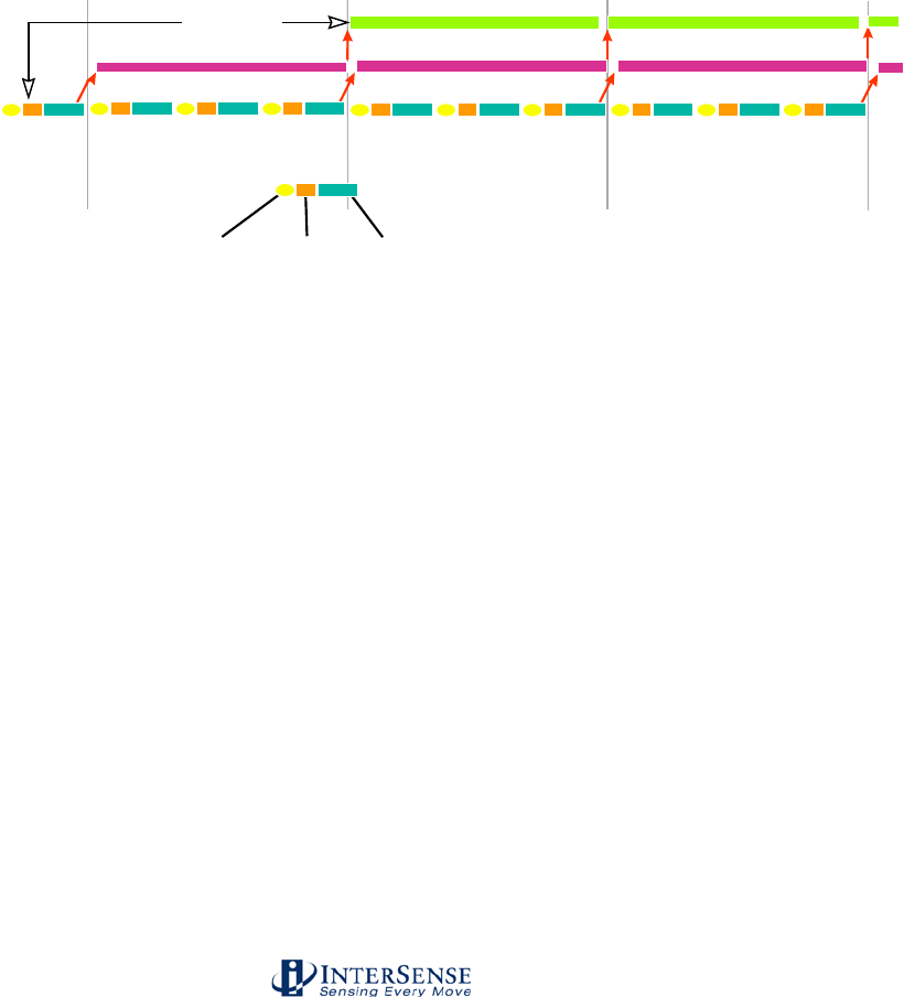
InterSense Doc. No. 072-00105-0I07 Rev. 4.2
IS-900 User Guide Page 144 of 177
11. Appendix F – GENLOCK Synchronization
11.1. Why Use GENLOCK?
GENLOCK synchronization is used to guarantee constant latency between the sampling of the
motion tracking sensor and the current image on the display device. Any change in the amount
of latency between these two events appears as jitter in orientation when the head is rotating.
For typical head rotation rates of 300 degrees/sec, a timing difference of 6.7 milliseconds will
result in orientation jitter of 2 degrees, which can be highly disturbing to the user.
On an IS-900 series product operating with no synchronization, the tracker will update at about
180 Hz, corresponding to a 5.6 ms period. Since the 180 Hz update rate of the tracker is
asynchronous with the update rate of the computer graphics rendering and display cycle, the
latency will vary by up to 5.6 ms from cycle to cycle, and thus GENLOCK synchronization is
essential if smooth response is desired during periods of moderately fast head rotation.
time(ms) 0 16.7 33.3 50.0
Display scan out
Rendering
Tracking
first
processing
stage
second
processing
stage
sample
InertiaCube
latency
1 2 3 4 5 6
Figure 42 - Timing Diagram: IS-900 Interfaced to PC with 60 Hz Display Refresh
Figure 42 illustrates the timing relationship of the tracking loop to the rendering loop with
GENLOCK in effect. The vertical lines at multiples of 16.7 milliseconds represent the vertical
sync pulses stripped from the 60 Hz VGA monitor cable. The tracker automatically determines
the frequency of the GENLOCK synchronization signal and then decides upon a tracking loop
update rate which is the highest multiple of this frequency that it can consistently maintain. In the
example in the diagram, the tracker has decided to do 3 internal updates per display refresh
cycle.
However, ONLY ONCE per display refresh cycle is data output across the serial or Ethernet port
to the host. This point, by default, is at the end of the last update cycle in the field, labeled 6 in
Figure 42. Using this point (or point 5) provides the lowest possible end-to-end latency, only 1
1/3 video fields in this example. So, if the total time to transmit the data across the
communication port plus the time to process and render the display is not guaranteed less than
16.7 ms on every single cycle, there will be cycles when the rendering does not complete for the
next scan out, resulting in a disturbing glitch in the image.
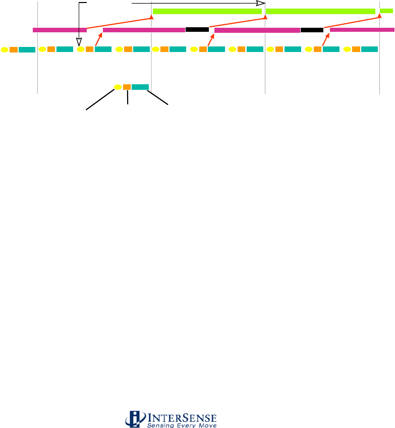
InterSense Doc. No. 072-00105-0I07 Rev. 4.2
IS-900 User Guide Page 145 of 177
By choosing to have the data port output occur at one of the earlier numbered phase points, there
is a bit more latency, but also more slack to allow for an occasional rendering cycle that just
slightly exceeds the allotted 16.7 ms.
Figure 43 illustrates the tracker set up to output data at phase point # 3. The timing slack has
absorbed this anomaly so that the image is still rendered with the same 1 2/3 frame latency as
the frames before it, resulting in no visual glitch. Of course, if there are several frames in a row
that run longer than 16.7 ms, the system will eventually drop a frame, resulting in a jarring
transition to 2 2/3 frame latency. To prevent this, the user must insure that the average frame
rate before attempting synchronization is ALWAYS above 60 Hz, so that once the
synchronization is enabled, the frame rate will be fixed at 60 Hz with no annoying shifts.
As a precaution, if the frame rate of the rendering engine drops below 60 Hz, the software driver
that is reading data from the tracker should always check to make sure that it is reading the latest
available data record. After reading a complete record, check to see if there are any further bytes
in the receive buffer, and if so wait for there to be a complete record and read it in replacing the
just read record. If this is implemented in the software driver, multiple data records could become
queued up in the ‘receive’ buffer, resulting in extra latency.
time(ms) 0 16.7 33.3 50.0
Display scan out
Rendering
Tracking
first
processing
stage
second
processing
stage
sample
InertiaCube
latency
1 2 3 4 5 6
Figure 43 - Timing Diagram: IS-900 Adjusted with Proper Phase for 60 Hz Display Refresh
The second reason why it may be desirable to adjust the output record transmission to an earlier
phase point is to allow for serial port transmission time. In the diagrams above, the slant of the
arrow pointing up from the tracking loop to the rendering loop represents the delay of transmitting
the results from the tracker to the host. If you use binary data mode, and set up the IS-900 to
only transmit 6 bytes of data (3 Euler angles plus 3 position values) using the command
O1,2,4<>, then the total number of bytes per record will be 29 which corresponds to 290 bits. At
a baud rate of 115,200 bits/sec, this record will take about 2.7 ms to transmit. Thus, the tightest
timing loop illustrated in the first diagram above can be achieved if the rendering time is always
less than (16.7 ms – 2.5 ms) = 14.2 ms, but it should probably not be attempted with any longer
output data record format or slower baud rate.
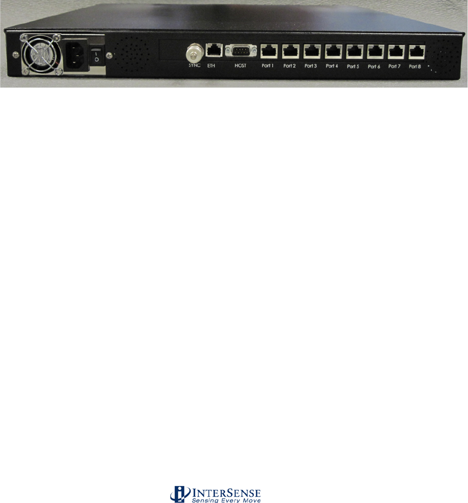
InterSense Doc. No. 072-00105-0I07 Rev. 4.2
IS-900 User Guide Page 146 of 177
11.2. Configuring the IS-900 for GENLOCK
The default operation of the tracker is free run. That is, the tracker performs updates
and, in continuous mode, outputs data records as rapidly as it can. GENLOCK
operation causes the tracker to synchronize updates and data record output to an
external sync signal or to an internal clock. When external GENLOCK is enabled and a
valid sync signal is provided, it may take several seconds to stabilize tracking. If a valid
signal not present, the tracker will wait an extra period for the signal, dropping the
update rate to half the sync rate. Details are discussed below.
Connecting Sync Signal
The external sync signal for GENLOCK on an IS-900 is on the back panel of the
processor shown in Figure 44.
Figure 44 - Back Panel of IS-900, SYNC IN is External GENLOCK Input
Connect the sync signal to the BNC connector labeled SYNC IN on the back of the IS-
900 Processor. The input interface setting for SYNC IN is controlled by software and
access is provided via command or the LCD menu. This setting is saved with the rest of
the user settings.
Command: MGS[source]<>
source
1
TTL
2
NTSC
Default is TTL. If source is omitted, the current setting is returned (31GS{source}<>).
From the LCD menu, GENLOCK source is selected by choosing: System Config →
GENLOCK → Source (TTL and NTSC options only).

InterSense Doc. No. 072-00105-0I07 Rev. 4.2
IS-900 User Guide Page 147 of 177
Enabling GENLOCK via Command
Send the C command to the tracker to place it in continuous mode. If the tracker is used
in polled mode, its internal updates will be synchronized to the sync signal but data
record output will not.
Send the InterSense-specific GENLOCK command to the tracker.
MG[state,[rate]]<>
State 0 Genlock off (free run)
1 Reserved—has no effect on the GENLOCK state.
2 Use external sync, strobe rate specified by rate parameter
(manual).
3 Use internal sync, output data records at frequency
specified by rate parameter.
rate For state 2, the sync strobe rate in hertz. For state 3, the
data record output rate in hertz. 30 Hz minimum in either
case.
Current settings of state and rate are reported if the command is issued without
parameters (or invalid ones).
The Fastrak command y{state}<> is not recognized by the IS-900, but has the
equivalent function the MG command with state equal to 0 or 1. If the Fastrak y{state}<>
command is used in your code, remember to manually configure GENLOCK via the LCD
menu to the settings required by the application.
ISDEMO can be used to send the GENLOCK command using the Send Command
String option. GENLOCK settings can be saved to the tracker using ISDEMO, using the
^K command or using the LCD (if equipped).
Enabling GENLOCK via LCD Menu
Select Communication→Data Output→Sample Mode→Continuous to place the tracker
in continuous mode. If the tracker is used in polled mode, its internal updates will be
synchronized to the sync signal but data record output will not.
Select System Config→GENLOCK→State and then one of the following choices.
Off GENLOCK off
Manual Use external sync (select strobe rate in 5 Hz increments
using arrow buttons, then press the enter button)
Internal Use internal sync (select data record output rate in 5 Hz
increments using arrows buttons, then press the enter
button)

InterSense Doc. No. 072-00105-0I07 Rev. 4.2
IS-900 User Guide Page 148 of 177
Verifying Synchronization
To verify GENLOCK is working with the IS-900, check the GENLOCK indicator in the
lower-right corner of the LCD on the front panel of the processor. When GENLOCK is
on and stable, the indicator displays “G”, otherwise the indicator displays an “X”
indicating GENLOCK is enabled but the processor is not synchronized. If “G” or “X” is
not displayed, then GENLOCK is off.
Using CrystalEyes™
To configure an IS-900 for use with CrystalEyes™, set the sync signal type to TTL and
send the command MG2,120 or MG2,60 to the tracker (assuming the video refresh rate
is 60 Hz or 120 Hz per eye). Connect the external sync signal used for the
CrystalEyes™ IR emitter to the SYNC IN on the back panel of the IS-900 Processor.
Adjusting Phase Point
A data record is output once per sync period when the tracker is in continuous mode.
The phase point is the time within the sync period at which a data record is transmitted
and is adjustable for internal and external GENLOCK. The phase point is specified as a
percentage of the sync period. 0% (the default) instructs the tracker to output a data
record as soon as possible after the sync period begins. 100% delays the output of a
record as much as possible before the next sync period begins. To adjust phase point
via command:
MGP[+/-]<> Increase/decrease to next/preceding phase point
MGP[p]<> Set phase point to percentage specified by p (0 to 100)
The current phase point is reported if the command is issued without parameters (or
invalid ones). The tracker will accept the first form of the command only after GENLOCK
is established. With the second form of the command, the tracker will match the
specified phase point as best it can, but typically with far less resolution than 1/100th of
the sync period.
To set the phase point via the LCD menu, select System Config→Genlock→Phase→Set
and change the value with the arrow buttons, then press the enter button. To increase
or decrease to the next or previous phase point, select System
Config→Genlock→Phase→Increase or →Decrease.
Adjust the phase to the latest point in the cycle (for minimum latency) such that the
system still behaves smoothly during head rotation (no render cycles last beyond the
deadline for the next scan out).

InterSense Doc. No. 072-00105-0I07 Rev. 4.2
IS-900 User Guide Page 149 of 177
12. Appendix G – Developers Instructions
For InterSense SDK Version 4.23 or higher.
12.1. Introduction
This document describes the interface to be used by the application software to initialize
and retrieve data from the InterSense devices using the InterSense library (isense.dll /
libisense.so / libisense.dylib). This library and API is provided to simplify communications
with all models of InterSense tracking devices. It can detect, configure, and get data
from up to 32 trackers, which may have multiple (up to 8) stations in some cases, such
as the IS-900 processor. The library maintains compatibility with existing devices, and
also makes the applications forward compatible with all future InterSense products. The
library is intended to be backwards compatible, in the sense that software written for
older versions of the DLL should generally run without recompilation using the current
version.
12.2. Sample Program
The library is distributed with sample programs written in C (all platforms), C# (Windows
only), and Visual Basic (Windows only) to demonstrate usage. It includes a header file
(isense.h) with data structure definitions and function prototypes. Most of the API
description below can also be obtained from the header file. The header file is heavily
commented and contains detailed information about the structures and function calls.
main.c Main loop of the program. All API calls are made from here.
isense.h Header file containing function prototypes and definitions, some of which
are only applicable to InterSense Professional Series devices and are not
used with InterTrax. This file should not be modified.
isense.c DLL import procedures. This file is included instead of an import library to
provide compatibility with all compilers.
isense.dll
libisense.so
libisense.dylib
The InterSense DLL and shared libraries. These files should be placed in
the Windows system directory, system library directory, or in the working
directory of the application (additional configuration may be required on
UNIX platforms).
dlcompat.c
dlcompat.h
Shared object import procedures for Mac OS X, not used on other
operating systems.

InterSense Doc. No. 072-00105-0I07 Rev. 4.2
IS-900 User Guide Page 150 of 177
12.3. Usage
The API provides an extensive set of functions that can read and set tracker
configuration, but in its simplest form can be limited to just 3 or 4 function calls, as
shown in the simple example below:
#include <stdio.h>
#include "isense.h"
#ifdef UNIX
#include <unistd.h>
#endif
void main()
{
ISD_TRACKER_HANDLE handle;
ISD_TRACKER_INFO_TYPE tracker;
ISD_TRACKING_DATA_TYPE data;
int i;
handle = ISD_OpenTracker((Hwnd)NULL, 0, FALSE, FALSE );
if ( handle > 0 )
printf( "\n Az El Rl X Y Z \n" );
else
printf( "Tracker not found. Press any key to exit" );
for (i=0; i < 20; i++) {
if ( handle > 0 ) {
ISD_GetTrackingData( handle, &data );
printf( "%7.2f %7.2f %7.2f %7.3f %7.3f %7.3f ",
data.Station[0].Euler[0],
data.Station[0].Euler[1],
data.Station[0].Euler[2],
data.Station[0].Position[0],
data.Station[0].Position[1],
data.Station[0].Position[2] );
ISD_GetCommInfo( handle, &tracker );
printf( "%5.2f Kb/s %d Rec/s \r",
tracker.KBitsPerSec, tracker.RecordsPerSec );
fflush(0);
}
#ifdef _WIN32
Sleep( 1000 );
#elif defined UNIX
usleep(1e6);
#endif
}
ISD_CloseTracker( handle );
}

InterSense Doc. No. 072-00105-0I07 Rev. 4.2
IS-900 User Guide Page 151 of 177
12.4. API
ISD_TRACKER_HANDLE
ISD_OpenTracker( HWND hParent,
DWORD commPort,
Bool infoScreen,
Bool verbose )
This function is used for opening a single tracker. It may be called multiple times in
order to open multiple trackers, though typically using ISD_OpenAllTrackers()is
recommended instead for use with multiple trackers.
hParent Handle to the parent window. This parameter is optional and should
only be used if information screen or tracker configuration tools are to
be used when available in the future releases. All included sample
programs pass NULL.
commPort If this parameter is a number other than 0, program will try to locate
an InterSense tracker on the specified RS232 port. Otherwise it looks
for USB device, then for serial port device on all ports at all baud
rates. Most applications should pass 0 for maximum flexibility. If you
have more than one InterSense device and would like to have a
specific tracker, connected to a known port, initialized first, then enter
the port number instead of 0.
infoScreen This feature has not been implemented. Its purpose is to display an
information window to show the tracker detection progress and
results. Currently DLL writes only to Windows console. Most
applications should pass FALSE.
verbose Pass TRUE if you would like a more detailed report of the DLL activity.
Messages are printed to Windows console.
DWORD
ISD_OpenAllTrackers( Hwnd hParent,
ISD_TRACKER_HANDLE *handle,
Bool infoScreen,
Bool verbose )
This function is used for opening multiple trackers. It returns an array of handles
for all detected trackers. -1 is returned on failure.
hParent Handle to the parent window. This parameter is optional and should
only be used if information screen or tracker configuration tools are to
be used when available in the future releases. All included sample
programs pass NULL.
handle An ISD_TRACKER_HANDLE array of size ISD_MAX_TRACKERS. This is
the recommended method for opening multiple trackers. The handle

InterSense Doc. No. 072-00105-0I07 Rev. 4.2
IS-900 User Guide Page 152 of 177
pointer will be populated with handles for all detected trackers when
this function returns.
infoScreen This feature has not been implemented. Its purpose is to display an
information window to show the tracker detection progress and
results. Currently DLL writes only to Windows console. Most
applications should pass FALSE.
verbose Pass TRUE if you would like a more detailed report of the DLL activity.
Messages are printed to Windows console.
Bool
ISD_CloseTracker( ISD_TRACKER_HANDLE handle )
This function call de-initializes the tracker, closes the communications port and
frees the resources associated with this tracker. If 0 is passed, all currently open
trackers are closed. When the last tracker is closed, the program frees the DLL.
Returns FALSE if failed for any reason.
handle Handle to the tracking device. This is a handle returned by
ISD_OpenTracker() or ISD_OpenAllTrackers().
Bool
ISD_GetTrackerConfig( ISD_TRACKER_HANDLE handle,
ISD_TRACKER_INFO_TYPE *Tracker,
Bool verbose )
Get general tracker information, such as type, model, port, etc. Also retrieves
Genlock synchronization configuration, if available. See the
ISD_TRACKER_INFO_TYPE structure definition for a complete list of items.
handle Handle to the tracking device. This is a handle returned by
ISD_OpenTracker() or ISD_OpenAllTrackers().
Tracker Pointer to a structure of type ISD_TRACKER_INFO_TYPE. The
structure definition is given below.
Bool
ISD_SetTrackerConfig( ISD_TRACKER_HANDLE handle,
ISD_TRACKER_INFO_TYPE *Tracker,
Bool verbose )

InterSense Doc. No. 072-00105-0I07 Rev. 4.2
IS-900 User Guide Page 153 of 177
When used with IS Precision Series (IS-300, IS-600, and IS-900) tracking
devices this function call will set ultrasonic and synchronization parameters, all
other fields in the ISD_TRACKER_INFO_TYPE structure are for information
purposes only.
handle Handle to the tracking device. This is a handle returned by
ISD_OpenTracker() or ISD_OpenAllTrackers().
Tracker Pointer to a structure of type ISD_TRACKER_INFO_TYPE. The
structure definition is given below.
Bool
ISD_GetCommInfo( ISD_TRACKER_HANDLE handle,
ISD_TRACKER_INFO_TYPE *Tracker)
Get RecordsPerSec and KBitsPerSec without requesting Genlock and other
settings from the tracker. Use this instead of ISD_GetTrackerConfig() to
prevent your program from stalling while waiting for the tracker response. This
call is used to obtain data rate information.
handle Handle to the tracking device. This is a handle returned by
ISD_OpenTracker() or ISD_OpenAllTrackers().
Tracker Pointer to a structure of type ISD_TRACKER_INFO_TYPE. The
structure definition is given below.
Bool
ISD_SetStationConfig( ISD_TRACKER_HANDLE handle,
ISD_STATION_INFO_TYPE *Station,
WORD stationID,
Bool verbose )
Configure station as specified in the ISD_STATION_INFO_TYPE structure. Before
this function is called, all elements of the structure must be assigned valid values.
General procedure for changing any setting is to first retrieve the current
configuration, make the changes, and then apply them. Calling
ISD_GetStationConfig() is important because you typically only want to
change some of the settings, leaving the rest unchanged.
This function is ignored if used with InterTrax products. IS-900, IS-600, IS-300
and InertiaCubes allow many parameters (including but not limited to
AngleFormat, Compass, Prediction, Enhancement, and Sensitivity) to be
changed.
handle Handle to the tracking device. This is a handle returned by
ISD_OpenTracker() or ISD_OpenAllTrackers().

InterSense Doc. No. 072-00105-0I07 Rev. 4.2
IS-900 User Guide Page 154 of 177
Station Pointer to a structure of type ISD_STATION_INFO_TYPE. The
structure definition is given below.
stationID Number from 1 to ISD_MAX_STATIONS.
Bool
ISD_GetStationConfig( ISD_TRACKER_HANDLE handle,
ISD_STATION_INFO_TYPE *Station,
WORD stationID,
Bool verbose )
Fills the ISD_STATION_INFO_TYPE structure with current settings.
handle Handle to the tracking device. This is a handle returned by
ISD_OpenTracker() or ISD_OpenAllTrackers().
Station Pointer to a structure of type ISD_STATION_INFO_TYPE. The
structure definition is given below.
stationID Number from 1 to ISD_MAX_STATIONS.
Bool
ISD_ConfigureFromFile( ISD_TRACKER_HANDLE handle,
char *path,
Bool verbose )
When a tracker is first opened, library automatically looks for a configuration file
in current directory of the application. File name convention is isenseX.ini where
X is a number, starting at 1, identifying the first tracking system in the order of
initialization. This function provides for a way to manually configure the tracker
using an arbitrary configuration file instead.
handle Handle to the tracking device. This is a handle returned by
ISD_OpenTracker() or ISD_OpenAllTrackers().
path Pointer to a string representing the complete path to the file to load.
Bool
ISD_ConfigSave( ISD_TRACKER_HANDLE handle )
Save tracker configuration. For devices with on-host processing, like the IS-900
PCTracker or PCI Tracker, this will write to the isenseX.cfg file. Serial port
devices like IS-300, IS-600 and IS-900 save configuration in the base unit, and
this call will just send a command to commit the changes to permanent storage.
handle Handle to the tracking device. This is a handle returned by
ISD_OpenTracker() or ISD_OpenAllTrackers().

InterSense Doc. No. 072-00105-0I07 Rev. 4.2
IS-900 User Guide Page 155 of 177
Bool
ISD_GetTrackingData( ISD_TRACKER_HANDLE handle,
ISD_TRACKING_DATA_TYPE *Data )
Get data from all configured stations. Data is places in the
ISD_TRACKING_DATA_TYPE structure. TimeStamp is only available if requested
by setting TimeStamped field to TRUE. Returns FALSE if failed for any reason.
handle Handle to the tracking device. This is a handle returned by
ISD_OpenTracker() or ISD_OpenAllTrackers().
Data Pointer to a structure of type ISD_TRACKER_DATA_TYPE. See below
for structure definition. Orientation data order is Yaw, Pitch, and Roll
for Euler angles and W, X, Y, Z for quaternions.
Bool
ISD_RingBufferSetup( ISD_TRACKER_HANDLE handle,
WORD stationID,
ISD_STATION_DATA_TYPE *dataBuffer,
DWORD samples )
By default, ISD_GetTrackingData() processes all records available from the
tracker and only returns the latest data. As the result, data samples can be lost if
it is not called frequently enough. If all the data samples are required, you can
use a ring buffer to store them. ISD_RingBufferSetup() accepts a pointer to
the ring buffer, and its size. Once activated, all processed data samples are
stored in the buffer for use by the application.
ISD_GetTrackingData() can still be used to read the data, but will return the
oldest saved data sample, then remove it from the buffer (FIFO). By repeatedly
calling ISD_GetTrackingData(), all samples are retrieved, the latest coming
last. All consecutive calls to ISD_GetTrackingData() will return the last sample,
but the NewData flag will be FALSE to indicate that the buffer has been emptied.
handle Handle to the tracking device. This is a handle returned by
ISD_OpenTracker() or ISD_OpenAllTrackers().
stationID Number from 1 to ISD_MAX_STATIONS.
dataBuffer An array of ISD_STATION_DATA_TYPE structures. Pass in NULL if you
do not need visibility into the complete buffer (typical).
samples The size of the ring buffer. ISD_GetTrackingData()should be called
frequently enough to avoid buffer overrun.

InterSense Doc. No. 072-00105-0I07 Rev. 4.2
IS-900 User Guide Page 156 of 177
Bool
ISD_RingBufferStart( ISD_TRACKER_HANDLE handle,
WORD stationID )
Activate the ring buffer. While active, all data samples are stored in the buffer.
Because this is a ring buffer, it will only store the number of samples specified in
the call to ISD_RingBufferSetup(), so the oldest samples can be overwritten.
handle Handle to the tracking device. This is a handle returned by
ISD_OpenTracker() or ISD_OpenAllTrackers().
stationID Number from 1 to ISD_MAX_STATIONS.
Bool
ISD_RingBufferStop( ISD_TRACKER_HANDLE handle,
WORD stationID )
Stop collection. The library will continue to process data, but the contents of the
ring buffer will not be altered.
handle Handle to the tracking device. This is a handle returned by
ISD_OpenTracker() or ISD_OpenAllTrackers().
stationID Number from 1 to ISD_MAX_STATIONS.
Bool
ISD_RingBufferQuery( ISD_TRACKER_HANDLE handle,
WORD stationID,
ISD_STATION_DATA_TYPE *currentData,
DWORD *head,
DWORD *tail )
Queries the library for the latest data without removing it from the buffer or
affecting the NewData flag. It also returns the indexes of the newest and the
oldest samples in the buffer. These can then be used to parse the buffer.
handle Handle to the tracking device. This is a handle returned by
ISD_OpenTracker() or ISD_OpenAllTrackers().
stationID Number from 1 to ISD_MAX_STATIONS.
currentData An array of ISD_STATION_DATA_TYPE used as the buffer.
head Pointer to the current head of the ring buffer.
tail Pointer to the current tail of the ring buffer.

InterSense Doc. No. 072-00105-0I07 Rev. 4.2
IS-900 User Guide Page 157 of 177
Bool
ISD_ResetHeading( ISD_TRACKER_HANDLE handle,
WORD stationID )
Reset heading (yaw) to zero.
handle Handle to the tracking device. This is a handle returned by
ISD_OpenTracker() or ISD_OpenAllTrackers().
stationID Number from 1 to ISD_MAX_STATIONS.
Bool
ISD_BoresightReferenced( ISD_TRACKER_HANDLE handle,
WORD stationID,
float yaw,
float pitch,
float roll )
Boresight station using specific reference angles. This is useful when you need to
apply a specific offset to system output. For example, if a sensor is mounted at 40
degrees relative to the HMD, you can enter 0, 40, 0 to get the system to output (0,
0, 0) for yaw, pitch, and roll, when the HMD is horizontal.
handle Handle to the tracking device. This is a handle returned by
ISD_OpenTracker() or ISD_OpenAllTrackers().
stationID Number from 1 to ISD_MAX_STATIONS.
yaw, pitch, roll
Boresight reference angles.
Bool
ISD_Boresight ( ISD_TRACKER_HANDLE handle,
WORD stationID,
Bool set )
Boresight, or unboresight a station. If 'set' is TRUE, all angles are reset to zero.
Otherwise, all boresight settings are cleared, including those set by
ISD_ResetHeading() and ISD_BoresightReferenced().
Note that the angles are reset relative to the current yaw; if the station is at 90
degrees yaw and 0 degrees pitch/roll when this function is called, rolling the
sensor (relative to its current heading) will be considered pitch, and pitch (relative
to its current heading) will be considered roll; it does not perform a boresight
'relative' to the current orientation vector.
handle Handle to the tracking device. This is a handle returned by
ISD_OpenTracker() or ISD_OpenAllTrackers().

InterSense Doc. No. 072-00105-0I07 Rev. 4.2
IS-900 User Guide Page 158 of 177
stationID Number from 1 to ISD_MAX_STATIONS.
set TRUE or FALSE, to set to clear boresight, respectively.
Bool
ISD_SendScript( ISD_TRACKER_HANDLE handle,
char *script )
Send a configuration script to the tracker. Script must consist of valid commands
as described in the interface protocol. Commands in the script should be
terminated by the newline character '\n'. The linefeed character '\r' is added by
the function and is not required.
Note that this may not be supported when using the shared memory interface,
such as with sfServer, and is primarily intended for the IS-300/IS-600/IS-900
system.
handle Handle to the tracking device. This is a handle returned by
ISD_OpenTracker() or ISD_OpenAllTrackers().
script Pointer to a string containing the command script.
Bool
ISD_AuxOutput( ISD_TRACKER_HANDLE handle,
WORD stationID,
BYTE *AuxOutput,
WORD length )
Sends up to 4 output bytes to the auxiliary interface of the station specified. The
number of bytes should match the number the auxiliary outputs the interface is
configured to expect. If too many are specified, extra bytes are ignored.
handle Handle to the tracking device. This is a handle returned by
ISD_OpenTracker() or ISD_OpenAllTrackers().
stationID Number from 1 to ISD_MAX_STATIONS.
AuxOutput An array of BYTEs to send.
length Size of AuxOutput.

InterSense Doc. No. 072-00105-0I07 Rev. 4.2
IS-900 User Guide Page 159 of 177
Bool
ISD_NumOpenTrackers( WORD *num )
The number of currently opened trackers is stored in the parameter passed to
this function.
float
ISD_GetTime( void )
Platform independent time function.
Bool
ISD_UdpDataBroadcast( ISD_TRACKER_HANDLE handle,
DWORD port,
ISD_TRACKING_DATA_TYPE *trackingData,
ISD_CAMERA_DATA_TYPE *cameraData )
Broadcast tracker data over the network using UDP broadcast.
handle Handle to the tracking device. This is a handle returned by
ISD_OpenTracker() or ISD_OpenAllTrackers().
port UDP port (0 to 65535).
trackingData A ISD_TRACKING_DATA_TYPE structure containing the data
to send, retrieved with ISD_GetTrackingData().
cameraData Pass NULL to this.
Bool
ISD_GetSystemHardwareInfo( ISD_TRACKER_HANDLE handle,
ISD_HARDWARE_INFO_TYPE *hwInfo )
Retrieve system hardware information. Note that the system is a single tracker
(and will thus have one handle). For details on individual stations (such as the
devices on each port of an IS-900), use ISD_GetStationHardwareInfo()
instead.
handle Handle to the tracking device. This is a handle returned by
ISD_OpenTracker() or ISD_OpenAllTrackers().
hwInfo An ISD_HARDWARE_INFO_TYPE structure containing the information.
The structure definition is given below.

InterSense Doc. No. 072-00105-0I07 Rev. 4.2
IS-900 User Guide Page 160 of 177
Bool
ISD_GetStationHardwareInfo( ISD_TRACKER_HANDLE handle,
ISD_STATION_HARDWARE_INFO_TYPE *info,
WORD stationID )
Retrieve station hardware information. Stations are individual devices (such as a
wand or head tracker) connected to a tracker (such as an IS-900).
handle Handle to the tracking device. This is a handle returned by
ISD_OpenTracker() or ISD_OpenAllTrackers().
info An ISD_STATION_HARDWARE_INFO_TYPE structure containing the
information. The structure definition is given below.
stationID Number from 1 to ISD_MAX_STATIONS.
Bool
ISD_GetPortWirelessInfo( ISD_TRACKER_HANDLE handle,
WORD port,
ISD_PORT_WIRELESS_INFO_TYPE *info )
Retrieve wireless configuration information.
handle Handle to the tracking device. This is a handle returned by
ISD_OpenTracker() or ISD_OpenAllTrackers().
port Station or port to get info from, starting at 0 for the first port.
info An ISD_PORT_WIRELESS_INFO_TYPE structure containing the
information. The structure definition is given below.

InterSense Doc. No. 072-00105-0I07 Rev. 4.2
IS-900 User Guide Page 161 of 177
12.5. Data Structures
12.5.1. ISD_TRACKER_INFO_TYPE
typedef struct {
float LibVersion;
DWORD TrackerType;
DWORD TrackerModel;
DWORD Port;
DWORD RecordsPerSec;
float KBitsPerSec;
DWORD SyncState;
float SyncRate;
DWORD SyncPhase;
DWORD Interface;
DWORD UltTimeout;
DWORD UltVolume;
DWORD dwReserved4;
float FirmwareRev;
float fReserved2;
float fReserved3;
float fReserved4;
Bool LedEnable;
Bool bReserved2;
Bool bReserved3;
Bool bReserved4;
}
ISD_TRACKER_INFO_TYPE;
LibVersion
InterSense library version (version of DLL or shared library).
TrackerType
One of the values defined in ISD_SYSTEM_TYPE
TrackerModel
One of the values defined in ISD_SYSTEM_MODEL
Port Number of the hardware port the tracker is connected to. Starts with 1.
RecordsPerSec
Communication statistics (number of data records/sec from tracker).
KBitsPerSec
Communications statistics (Kb/sec of data from tracker).

InterSense Doc. No. 072-00105-0I07 Rev. 4.2
IS-900 User Guide Page 162 of 177
SyncState
Applies to IS-X Series devices only. Can be one of 4 values:
0 - OFF, system is in free run
1 – Not used
2 - ON, hardware genlock frequency is specified by the user
3 - ON, no hardware signal, lock to the user specified frequency
SyncRate
Sync frequency - number of hardware sync signals per second, or, if SyncState
is 3 - data record output frequency.
SyncPhase
The time within the sync period at which a data record is transmitted. The phase
point is specified as a percentage of the sync period. 0% (the default) instructs
the tracker to output a data record as soon as possible after the sync period
begins. 100% delays the output of a record as much as possible before the next
sync period begins.
Interface
Hardware interface type, as defined in ISD_INTERFACE_TYPE.
UltTimeout
IS-900 only, ultrasonic timeout (sampling rate).
UltVolume
IS-900 only, ultrasonic speaker volume.
FirmwareRev
Firmware revision for tracker.
LedEnable
IS-900 only, blue led on the SoniDiscs enable flag.

InterSense Doc. No. 072-00105-0I07 Rev. 4.2
IS-900 User Guide Page 163 of 177
12.5.2. ISD_STATION_INFO_TYPE
This data structure is used to get and set station configuration, using
ISD_GetStationConfig() and ISD_SetStationConfig().
typedef struct {
DWORD ID;
Bool State;
Bool Compass;
LONG InertiaCube;
DWORD Enhancement;
DWORD Sensitivity;
DWORD Prediction;
DWORD AngleFormat;
Bool TimeStamped;
Bool GetInputs;
Bool GetEncoderData;
BYTE CompassCompensation;
BYTE ImuShockSuppression;
BYTE UrmRejectionFactor;
BYTE bReserved2;
DWORD CoordFrame
DWORD AccelSensitivity;
float fReserved1;
float fReserved2;
float TipOffset[3];
float fReserved3;
Bool GetCameraData;
Bool GetAuxInputs;
Bool GetCovarianceData;
Bool GetExtendedData;
}
ISD_STATION_INFO_TYPE;
ID A unique number identifying a station. It is the same as that passed to the
ISD_SetStationConfig() and ISD_GetStationConfig() functions and can be
1 to ISD_MAX_STATIONS.
State
TRUE if on, FALSE if off. InertiaCubes are considered to be a tracking system
consisting of one station, which cannot be turned off, so this field will always be
TRUE. The IS-900 may have up to 7 stations connected.
Compass
Only available for InertiaCube devices. For all others this setting is always 2.
This controls the state of the compass component of the InertiaCube. Compass
is only used when station is configured for GEOS or Dual modes, in Fusion mode
compass readings are not used, regardless of this setting. When station is
configured for full compass mode, the readings produced by the magnetometers
inside the InertiaCube are used as absolute reference orientation for yaw.
Compass can be affected by metallic objects and electronic equipment in close
proximity to an InertiaCube. Older versions of tracker firmware supported only

InterSense Doc. No. 072-00105-0I07 Rev. 4.2
IS-900 User Guide Page 164 of 177
0 and 1, which stood for ON or OFF. Please use the new notation. This API will
correctly interpret the settings.
InertiaCube
InertiaCube associated with this station. If no InertiaCube is assigned, this
number is -1. Otherwise, it is a positive number 1 to ISD_MAX_STATIONS.
Only relevant for IS-300 and IS-600 Series devices. For IS-900 systems, it is
always the same as the station number, for InterTrax and InertiaCubes it’s
always 1.
Enhancement
In order to provide the best performance for a large range of various applications,
three levels of perceptual enhancement are available. None of the modes introduces
any additional latency. The InterTrax is restricted to Mode 2.
Mode 0 provides the best accuracy. The inertial tracker uses gyros to measure
angular rotation rates for computing the sensor’s orientation. To compensate for the
gyroscopic drift, depending on the configuration, the tracker may use
accelerometers, magnetometers or SoniDiscs to measure the actual physical
orientation of the sensor. That data is then used to compute the necessary
correction. In Mode 0 correction adjustments are made immediately, no jitter
reduction algorithms are used. This results in somewhat jumpy output (not
recommended for head tracking) but with lower RMS error. Use this mode for
accuracy testing or for any application that requires best accuracy.
Mode 1 provides accuracy similar to that of mode 0, with an addition of a jitter
reduction algorithm. This algorithm reduces the accuracy by only a small amount and
does not add any latency to the measurements. Mode 1 is recommended for
augmented reality applications (i.e. overlaying or mixing both virtual and real objects
in a visualization system.)
Mode 2 is recommended for use with HMD or other immersive applications. The
drift correction adjustments are made smoothly and only while the sensor is
moving, so as to be transparent to the user.
Sensitivity
This setting is only used when Perceptual Enhancement Level is set to 1 or 2. It
controls the minimum angular rotation rate picked up by the InertiaCube. Default
is level 3. Increasing sensitivity does not increase latency during normal
movements. It may, however, result in some small residual movements for a
couple of seconds after the sensor has stopped. If your application requires
sensitivity greater than maximum provided by this control, you must use
Perceptual Enhancement level 0. For InterTrax this value is fixed to default and
can’t be changed.

InterSense Doc. No. 072-00105-0I07 Rev. 4.2
IS-900 User Guide Page 165 of 177
Prediction
Inertial sensors can predict motion up to 50 ms into the future, which
compensates for graphics rendering delays and further contributes to eliminating
simulator lag. Supported by IS-300, IS-600, IS-900 and InertiaCubes. Not
available for the InterTrax.
AngleFormat
ISD_EULER or ISD_QUATERNION. The Euler angles are defined as rotations
about Z, then Y, then X in body frame. Angles are returned in degrees. Default is
ISD_EULER.
TimeStamped
TRUE if time stamp is requested, default is FALSE.
GetInputs
TRUE if button and joystick data is requested, default is FALSE.
GetEncoderData
TRUE if raw encoder data is requested, default is FALSE.
CompassCompensation
This setting controls how Magnetic Environment Calibration is applied. This
calibration calculates nominal field strength and dip angle for the environment in
which the sensor is used. Based on these values, the system can assign a
weight to compass measurements, allowing it to reject bad measurements.
Values from 0 to 3 are accepted. If CompassCompensation is set to 0, the
calibration is ignored and all compass data is used. Higher values result in a
tighter rejection threshold, resulting in more measurements being rejected. If the
sensor is used in an environment with significant magnetic interference this can
result in drift due to insufficient compensation from the compass data. Default
setting is 2.
Note that the sensor must be calibrated in the ISDemo Compass Calibration Tool
for this setting to have any effect.
ImuShockSuppression
This setting controls how the system deals with sharp changes in IMU data that
can be caused by shock or impact. Sensors may experience momentary rotation
rates or accelerations that are outside of the specified range, resulting in
undesirable behavior. By turning on shock suppression you can have the system
filter out corrupted data. Values 0 (OFF) to 2 are accepted, with higher values
resulting in greater filtering.
ImuShockSuppression
This setting controls the rejection threshold for ultrasonic measurements.
Currently, it is implemented only for the IS-900 PCTracker. Default setting is 4,
which results in measurements with range errors greater than 4 times the
average to be rejected. Please do not change this setting without first consulting
with InterSense technical support.

InterSense Doc. No. 072-00105-0I07 Rev. 4.2
IS-900 User Guide Page 166 of 177
CoordFrame
Coordinate frame in which position and orientation data is reported. Can be
ISD_DEFAULT_FRAME or ISD_VSET_FRAME. Second is used for camera tracker
only. Default is ISD_DEFAULT_FRAME.
AccelSensitivity
AccelSensitivity is used for 3-DOF tracking with InertiaCube products only. It
controls how fast tilt correction, using accelerometers, is applied. Valid values
are 1 to 4, with 2 as default.
Level 1 reduces the amount of tilt correction during movement. While it will
prevent any effect linear accelerations may have on pitch and roll, it will also
reduce stability and dynamic accuracy. It should only be used in situations when
sensor is not expected to experience a lot of movement.
Level 2 (default) is best for head tracking in static environment, with user seated.
Level 3 allows for more aggressive tilt compensation, appropriate when sensor is
moved a lot, for example, when the user is walking for long periods of time.
Level 4 allows for even greater tilt corrections. It will reduce orientation accuracy
by allowing linear accelerations to effect orientation, but increase stability. This
level is appropriate for when the user is running, or in other situations where the
sensor experiences a great deal of movement.
TipOffset
Offset of the reported position from the physical point being tracked. This is only
applicable to system capable of tracking position.
GetCameraData
TRUE to get computed FOV, aperture, etc. default is FALSE.
GetAuxInputs
TRUE to get values from auxiliary inputs connected to the I2C port in the
MicroTrax device.

InterSense Doc. No. 072-00105-0I07 Rev. 4.2
IS-900 User Guide Page 167 of 177
12.5.3. ISD_TRACKING_DATA_TYPE
This data structure is used to return current data for a station, including position,
orientation, time stamp, button and analog channel state. It is passed to
ISD_GetTrackingData() as part of ISD_TRACKING_DATA_TYPE
typedef struct {
ISD_STATION_DATA_TYPE Station[ISD_MAX_STATIONS];
}
ISD_TRACKING_DATA_TYPE;
typedef struct {
BYTE TrackingStatus;
BYTE NewData;
BYTE CommIntegrity;
BYTE BatteryState
float Euler[3];
float Quaternion[4];
float Position[3];
float TimeStamp;
float StillTime;
float BatteryLevel;
float CompassYaw;
Bool ButtonState[ISD_MAX_BUTTONS];
short AnalogData[ISD_MAX_CHANNELS];
BYTE AuxInputs[ISD_MAX_AUX_INPUTS];
float AngularVelBodyFrame[3];
float AngularVelNavFrame[3];
float AccelBodyFrame[3];
float AccelNavFrame[3];
float VelocityNavFrame[3];
float AngularVelRaw[3];
BYTE MeasQuality;
BYTE bReserved2;
BYTE bReserved3;
BYTE bReserved4;
DWORD TimeStampSeconds;
DWORD TimeStampMicroSec;
DWORD OSTimeStampSeconds;
DWORD OSTimeStampMicroSec;
float Reserved[56];
float MagBodyFrame[3];
}
ISD_STATION_DATA_TYPE;

InterSense Doc. No. 072-00105-0I07 Rev. 4.2
IS-900 User Guide Page 168 of 177
TrackingStatus
Tracking status byte. Available only with IS-900 firmware versions 4.13 and
higher, and isense.dll versions 3.54 and higher. It is a value from 0 to 255 that
represents tracking quality. 0 represents lost.
NewData
TRUE if this is new data. Every time ISD_GetData() is called this flag is reset.
CommIntegrity
Communication integrity of wireless link (percentage of packets received from
tracker, 0-100%)
BatteryState
Certain wireless devices only (0=N/A, 1=Low, 2=OK). Not currently used by
MiniTrax or MicroTrax stations.
Euler Orientation in Euler angle format (Yaw, Pitch, Roll)
Quaternion
Orientation in Quaternion format (W,X,Y,Z)
Position
Station position in meters.
TimeStamp
Timestamp in seconds, reported only if requested
StillTime
InertiaCube and PC-Tracker products only, whether sensor is still
BatteryLevel
Battery voltage, if available
CompassYaw
Magnetometer heading, computed based on current orientation. Available for
InertiaCube products only, such as IC2, IC3 and IC2+
ButtonState
Only if requested.
AnalogData
Only if requested. Current hardware is limited to 10 channels, only 2 are used.
The only device using this is the IS-900 wand that has a built-in analog joystick.
Channel 1 is x-axis rotation, channel 2 is y-axis rotation. Values are from 0 to
255, with 127 representing the center.
AuxInputs
Only if requested.

InterSense Doc. No. 072-00105-0I07 Rev. 4.2
IS-900 User Guide Page 169 of 177
AngularVelBodyFrame
rad/sec, in sensor body coordinate frame. Reported as rates about X, Y and Z
axes, corresponding to Roll, Pitch, Yaw order. This is the processed angular rate,
with current biases removed. This is the angular rate used to produce orientation
updates.
AngularVelNavFrame
rad/sec, in world coordinate frame, with boresight and other transformations
applied. Reported as rates about X, Y and Z axes, corresponding to Roll, Pitch,
Yaw order.
AccelBodyFrame
meter/sec^2, in sensor body coordinate frame. These are the accelerometer
measurements in the sensor body coordinate frame. Only factory calibration is
applied to this data, gravity component is not removed. Reported as
accelerations along X, Y and Z axes.
AccelNavFrame
meters/sec^2, in the navigation (earth) coordinate frame. This is the
accelerometer measurements with calibration, current sensor orientation applied,
and gravity subtracted. This is the best available estimate of tracker acceleration.
Reported as accelerations along X, Y and Z axes.
VelocityNavFrame
meters/sec, 6-DOF systems only. Reported as velocity along X, Y and Z axes.
AngularVelRaw
Raw gyro output, only factory calibration is applied. Some errors due to
temperature dependant gyro bias drift will remain.
MeasQuality
Ultrasonic Measurement Quality (IS-900 only, firmware >= 4.26)
TimeStampSeconds
Time Stamp in whole seconds.
TimeStampMicroSec
Fractional part of the Time Stamp in micro-seconds.
OSTimeStampSeconds
OSTimeStampMicroSec
Data record arrival time stamp based on OS time, reserved for future use, not
implemented.
MagBodyFrame
3DOF sensors only. Magnetometer data along the X, Y, and Z axes. Units are
nominally in Gauss, and factory calibration is applied. Note, however, that most
sensors are not calibrated precisely since the absolute field strength is not

InterSense Doc. No. 072-00105-0I07 Rev. 4.2
IS-900 User Guide Page 170 of 177
necessary to for tracking purposes. Relative magnitudes should be accurate,
however. Fixed metal compass calibration may rescale the values.

InterSense Doc. No. 072-00105-0I07 Rev. 4.2
IS-900 User Guide Page 171 of 177
12.5.4. ISD_HARDWARE_INFO_TYPE
This data structure is used to return system hardware information using
ISD_GetSystemHardwareInfo(). For more detailed descriptions of elements in the
structure, please reference the comments in the isense.h file.
typedef struct {
Bool Valid;
DWORD TrackerType;
DWORD TrackerModel;
DWORD Port;
DWORD Interface;
Bool OnHost;
DWORD AuxSystem;
float FirmwareRev;
char ModelName[128];
struct {
Bool Position;
Bool Orientation;
Bool Encoders;
Bool Prediction;
Bool Enhancement;
Bool Compass;
Bool SelfTest;
Bool ErrorLog;
Bool UltVolume;
Bool UltGain;
Bool UltTimeout;
Bool PhotoDiode;
DWORD MaxStations;
DWORD MaxImus;
DWORD MaxFPses;
DWORD MaxChannels;
DWORD MaxButtons;
Bool MeasData;
Bool DiagData;
Bool PseConfig;
Bool ConfigLock;
float UltMaxRange;
float fReserved2;
float fReserved3;
float fReserved4;
Bool CompassCal;
Bool bReserved2;
Bool bReserved3;
Bool bReserved4;
DWORD dwReserved1;

InterSense Doc. No. 072-00105-0I07 Rev. 4.2
IS-900 User Guide Page 172 of 177
DWORD dwReserved2;
DWORD dwReserved3;
DWORD dwReserved4;
}
Capability;
Bool bReserved1;
Bool bReserved2;
Bool bReserved3;
Bool bReserved4;
DWORD BaudRate;
DWORD NumTestLevels;
DWORD dwReserved3;
DWORD dwReserved4;
float fReserved1;
float fReserved2;
float fReserved3;
float fReserved4;
char cReserved1[128];
char cReserved2[128];
char cReserved3[128];
char cReserved4[128];
}
ISD_HARDWARE_INFO_TYPE;

InterSense Doc. No. 072-00105-0I07 Rev. 4.2
IS-900 User Guide Page 173 of 177
12.5.5. ISD_STATION_HARDWARE_INFO_TYPE
This data structure is used to return station (individual tracking device) hardware
information using ISD_GetStationHardwareInfo(). For more detailed descriptions of
elements in the structure, please reference the comments in the isense.h file.
typedef struct {
Bool Valid;
DWORD ID;
char DescVersion[20];
float FirmwareRev;
DWORD SerialNum;
char CalDate[20];
DWORD Port;
struct {
Bool Position;
Bool Orientation;
DWORD Encoders;
DWORD NumChannels;
DWORD NumButtons;
DWORD AuxInputs;
DWORD AuxOutputs;
Bool Compass;
Bool bReserved1;
Bool bReserved2;
Bool bReserved3;
Bool bReserved4;
DWORD dwReserved1;
DWORD dwReserved2;
DWORD dwReserved3;
DWORD dwReserved4;
}
Capability;
Bool bReserved1;
Bool bReserved2;
Bool bReserved3;
Bool bReserved4;
DWORD Type;
DWORD DeviceID;
DWORD dwReserved3;
DWORD dwReserved4;
float fReserved1;
float fReserved2;
float fReserved3;
float fReserved4;
char cReserved1[128];
char cReserved2[128];
char cReserved3[128];
char cReserved4[128];
}
ISD_STATION_HARDWARE_INFO_TYPE;

InterSense Doc. No. 072-00105-0I07 Rev. 4.2
IS-900 User Guide Page 174 of 177
12.5.6. ISD_PORT_WIRELESS_INFO_TYPE
This data structure is used to information about the wireless hardware on a given port,
using ISD_GetPortWirelessInfo(). The radioVersion field can be used to check
the type of radio hardware:
2.4 GHz (Aerocomm, radio used with older MiniTrax trackers): 15 or 31
2.4 GHz (Chipcon, MicroTrax only): 128
900 MHz (MicroTrax only): 144
868 MHz (MicroTrax only): 160
typedef struct {
Bool valid;
LONG status;
Bool wireless;
DWORD channel;
DWORD id[4];
DWORD radioVersion;
DWORD dReserved1;
DWORD dReserved2;
DWORD dReserved3;
DWORD dReserved4;
}
ISD_PORT_WIRELESS_INFO_TYPE;

InterSense Doc. No. 072-00105-0I07 Rev. 4.2
IS-900 User Guide Page 175 of 177
13. Appendix H – Interface Protocol Commands –
Quick Reference
For further detail, see:
Section 4.2 Standard Fastrak™ Interface Commands, pages 63-71.
Section 4.3 Fastrak™ Commands Implemented for Compatibility, page 71.
Section 4.4 InterSense specific Commands, pages 71-80.
NOTE: “<>” represents a newline character, and “^” represents a control character
Command Syntax
Data Record Request P
Output mode C Set continuous output mode
c Set polled output mode
Alignment Reference Frame A{stationNum},[Ox,Oy,Oz,Xx,Xy,Xz,Yx,Yy,Yz]<>
Reset Alignment Reference Frame R{stationNum}<>
Boresight Reference Angles G{stationNum},[yawref, pitchref, rollref]<>
Boresight Compatibility Mode MBF<> Switch to Fastrak Compatible mode.
MBI<> Switch to Version 2.x Compatible mode (default).
Boresight B{stationNum}<> (Fastrak compatibility mode)
MB{stationNum}<> (Version 2.x compatibility mode)
Unboresight b{stationNum}<> (Fastrak compatibility mode)
Mb{stationNum}<> (Version 2.x compatibility mode)
Heading Boresight B{stationNum}<> (Version 2.x compatibility mode)
MB{stationNum}<> (Fastrak compatibility mode)
Heading Unboresight b{stationNum}<> (Version 2.x compatibility mode)
Mb{stationNum}<> (Fastrak compatibility mode)
.
Set Serial Communication Parameters o{rate,parity,bits,HHS}<>
System Record Request S
Station Status l{stationNum},[state]<>
Output Units Control U Set units to inches.
u Set units to centimeters.
System control ^K Save current settings to non-volatile memory.
W Restore factory default settings.
^Y Restart the firmware to the power up condition.
^S Suspend data transmission.
^Q Resume data transmission.
Output record mode F Put in ASCII output mode.
f Put in Binary output mode.

InterSense Doc. No. 072-00105-0I07 Rev. 4.2
IS-900 User Guide Page 176 of 177
Output record list settings O{stationNum},[p1],[p2],[p3],.....,[pn]<>
Define Tip Offsets N{stationNum},[Ox, Oy, Oz]<>
Position Operational Envelope V{stationNum},[Xmax,Ymax,Zmax,Xmin,Ymin,Zmin]<>
Hemisphere H{stationNum},[p1,p2,p3]<>
Time Units MT<> Sets to milliseconds.
Mt<> Sets to microseconds.
Set Current Time to Zero MZ<>
Ethernet Communication Parameters MEthIp{address}<> Set IP address
MEthTcpPort{port}<> Set TCP port
MEthUdp{state}<> Set UDP state
MEthUdpPort{port}<> Set UDP port
MEthSubnet{subnet}<> Set subnet
MEthMode{mode}<> Set manual or DHCP mode
MEthApply<> Apply Ethernet settings
InterSense System Status Record Request MS<>
Tracking Status Record Request MP<>
Genlock Synchronization MG[State, Rate]<>
Genlock Phase MGP[Param]<>
Configuration Lock MConfigLockMode{Mode}<>
SoniStrip LED Control ML[state]
Error reporting ME<>
MEC<>
ME1<>
ME0<>
Command Logging MLogOpen<>
MLogClose<>
MLogClear<>
MLogState<>
MLogSend<>
InterSense Station Status Record Request Ms{stationNum}<>
Prediction Interval Mp{stationNum},[Interval]<>
Perceptual Enhancement Level MF{stationNum},{Mode}<>
Compass Heading Correction MH{stationNum},{state}<>
Rotational Sensitivity Level MQ{stationNum},[Sensitivity Level]<>
Associate Fixed PSE with a Constellation MCF{FPSE number}, {xp, yp, zp, xn, yn, zn, IDcode}<>
Disassociate Fixed PSE from Constellation MCf[Fixed PSE number, IDcode]<>
Clear All Fixed PSEs (Constellation) MCC<>
Apply New Configuration MCe<>
Cancel Configuration Session MCx<>

InterSense Doc. No. 072-00105-0I07 Rev. 4.2
IS-900 User Guide Page 177 of 177
[END]