Thales e Transactions P4432-051 Point of Sale Terminal User Manual OM 01016529 Rev 1

Thales e- Transactions S.A. Point of Sale Terminal OM 01016529 Rev 1

Contents

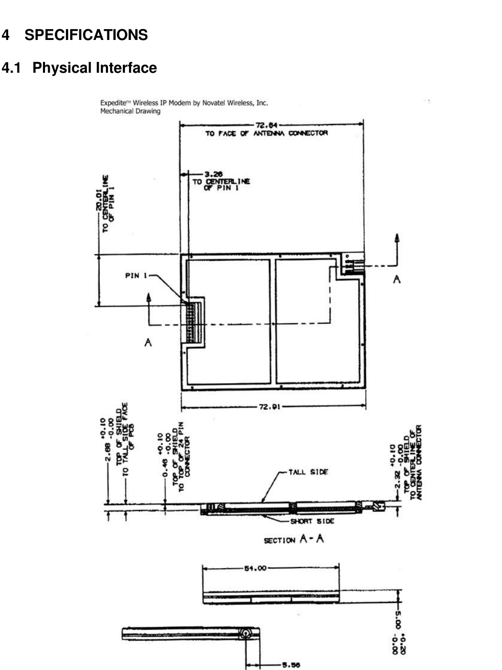
Expedite Hardware Spec

Hardware InterfaceSpecificationforExpedite™ Wireless IP ModemNovatel Wireless, Inc.6540 Lusk Boulevard, Suite C-166San Diego, CA 92121888-888-9231www.novatelwireless.comOM - 01016529Revision 1
The information disclosed herein is the exclusive property of NOVATEL WIRELESS, INC. and is not tobe disclosed without the written consent of NOVATEL WIRELESS, INC. No part of this publication maybe reproduced or transmitted in any form or by any means including electronic storage, reproduction,execution or transmission without the prior written consent of NOVATEL WIRELESS, INC. The recipientof this document by its retention and use, agrees to respect the security status of the informationcontained herein.The information disclosed herein is the exclusive property of Novatel Wireless, Inc. and is not to bedisclosed without the written consent of NOVATEL WIRELESS, INC.  No part of this publication may bereproduced or transmitted in any form or by any means including electronic storage, reproduction,execution or transmission without the prior written consent of NOVATEL WIRELESS, INC. The recipientof this document by its retention and use, agrees to respect the security status of the informationcontained herein.The information contained in this document is subject to change without notice and should not beconstrued as a commitment by NOVATEL WIRELESS, INC. unless such commitment is expressly givenin a covering document.© Copyright 1999 NOVATEL WIRELESS, INC. All rights reserved.Expedite is a trademark of NOVATEL WIRELESS, INC.
Table of Contents1WARNING........................................................................................................................................42INTRODUCTION..............................................................................................................................43SCOPE.............................................................................................................................................44SPECIFICATIONS ...........................................................................................................................54.1 Physical Interface ......................................................................................................................54.1.1 Data/Power Connection ......................................................................................................64.1.2 RF Antenna Connector Type...............................................................................................64.1.3 Pin Descriptions..................................................................................................................74.2 Host Interface Specifications .....................................................................................................84.2.1 Serial Data Rate and Format ..............................................................................................84.3 Radio Specifications ..................................................................................................................84.3.1 Airlink Data Rate.................................................................................................................84.3.2 Recommended Antenna Type.............................................................................................84.3.3 Frequency Range ...............................................................................................................84.3.4 Duplex Mode ......................................................................................................................84.3.5 RF Power Class..................................................................................................................84.4 Electrical Specifications.............................................................................................................94.5 Mechanical Specifications........................................................................................................104.5.1 Dimensions.......................................................................................................................104.5.2 Weight..............................................................................................................................104.6 Environmental Specifications...................................................................................................104.6.1 Temperature Range..........................................................................................................104.6.2 Humidity ...........................................................................................................................104.6.3 ...............................................................................................................................................104.6.4 Shock Stability..................................................................................................................104.6.5 Vibration Stability..............................................................................................................104.6.6 Regulatory compliance .....................................................................................................104.6.7 ESD Protection.................................................................................................................104.7 CDPD Part 409 Compliance ....................................................................................................115INSTALLATION INSTRUCTIONS..................................................................................................115.1 Antenna Mounting....................................................................................................................125.2 Antenna...................................................................................................................................125.3 Labeling...................................................................................................................................125.4 User Manual ............................................................................................................................126PACKAGING REQUIREMENTS ....................................................................................................136.1 Shipping Packaging.................................................................................................................136.2 Labeling...................................................................................................................................13
1 WARNINGAll persons must be at least 20 cm from the antenna when transmitter operating to meet FCC RFexposure requirements. Refer to the Installation Instructions section for specific requirements for theantenna used with module.2 INTRODUCTIONThis document describes the hardware interface for the Novatel Wireless Expedite Wireless IP Modem.The Expedite Wireless IP Modem is an OEM module designed for integration into a host product toprovide two-way wireless data communication capability via the CDPD (Cellular Digital Packet Data)Network.3 SCOPEThe scope of this document includes all pertinent information for describing the capabilities andoperating requirements for the product in order to determine suitability for specific market applications.Internal design issues, detailed operating instructions and cost information is not included in thisdocument.
4 SPECIFICATIONS4.1 Physical Interface
4.1.1 Data/Power ConnectionOne connector is used to physically connect the power supply and 3.3 volt logic level hostcommunication interface signals to the Expedite Wireless IP Modem.4.1.1.1 Data/Power Connector TypeDescription: 24-pin, 1.27 mm pitch, SMT, double row low profile socket typeSamtec part number:  CLP-112-02-F-DSome interface connector options are provided here for reference.  Contact Samtec for the latestconnector mating options.4.1.1.2 Surface Mount Mating Connector OptionsDescription: 24-pin, 1.27 mm pitch, SMT, double row, zero profile, pin type headerSamtec part number:  DIS5-112-52-F-D-VSNOTE:  This connector provides the lowest profile interface solution.Description: 24-pin, 1.27 mm pitch, SMT, double row, low profile, pin type headerSamtec part number:  FTS-112-03-F-DV4.1.1.3 Through-Hole Mating Connector OptionsDescription: 24-pin, 1.27 mm pitch, T/H, double row, zero profile, pin type headerSamtec part number:  DIS5-112-52-F-DDescription: 24-pin, 1.27 mm pitch, T/H, double row, low profile, pin type headerSamtec part number:  FTS-112-03-F-D4.1.2 RF Antenna Connector TypeExpedite Wireless IP Modem antenna connector:Description -MMCX Coaxial ConnectorManufacturer -Huber and SuhnerPart Number -82MMCX-S50-0-2NOTE: An equivalent connector by the same or another manufacturer may be used.Impedance -50 ohmExpedite Wireless IP Modem mating antenna connector:Mating connector:  -AEP 8905-1521-003 or equivalent with RG316 cable.
4.1.3 Pin DescriptionsPin # Name Direction Power-onReset State Description13, 14 Vcc1 POWER POWER SUPPLY CONNECTION TO THE MODEM FOR ALLCIRCUITRY EXCEPT FOR THE RF POWER AMPLIFIER.15, 16 Vcc2 POWER POWER SUPPLY CONNECTION TO THE MODEM FOR THE RFPOWER AMPLIFIER ONLY1,2 &23,24 GND POWER MODEM GROUND3PWR_IND OUTPUT POWER INDICATOR:HI: INDICATES THAT THE MODEM IS ONLO INDICATES THAT THE MODEM IS OFF5SM_IND OUTPUT SLEEP MODE  INDICATOR:HI: INDICATES THAT THE MODEM IS IN SLEEP MODELO INDICATES THAT THE MODEM IS NOT IN SLEEP MODE4WKUP INPUT WAKE UP INPUT:  (ACTIVE HI PULSE)A PULSE APPLIED TO THIS PIN WILL TURN ON THE MODEM IFTHE MODEM IS OFF, OR WAKE  UP THE MODEM IF THE MODEM ISIN SLEEP MODE. REFER TO THE APPLICATIONS INFORMATIONSECTION FOR MORE DETAILS ON USING THE WAKE UP PIN.6DTM INPUT DATA TO MODEM:(3.3 VOLT LOGIC LEVEL)IN RS232 TERMS, THIS IS CALLED "TXD".7DFM OUTPUT DATA FROM MODEM:(3.3 VOLT LOGIC LEVEL)IN RS232 TERMS, THIS IS CALLED "RXD".11 RTS INPUT READY TO SEND:(3.3 VOLT LOGIC LEVEL)10 CTS OUTPUT CLEAR TO SEND:(3.3 VOLT LOGIC LEVEL)8DTR INPUT DTE READY:(3.3 VOLT LOGIC LEVEL)9DSR OUTPUT DCE READY:(3.3 VOLT LOGIC LEVEL)12 GPIO1 BI-DIRECTIONAL INPUT WITHPULLUP GENERAL PURPOSE CONFIGURABLE INPUT OR OUTPUT:REFER TO THE AT COMMAND SET FOR THE DEFAULT STATE.17 GPIO2 BI-DIRECTIONAL INPUT WITHPULLUP GENERAL PURPOSE CONFIGURABLE INPUT OR OUTPUT:REFER TO THE AT COMMAND SET FOR THE DEFAULT STATE.18 GPIO3 BI-DIRECTIONAL INPUT WITHPULLDOWN GENERAL PURPOSE CONFIGURABLE INPUT OR OUTPUT:REFER TO THE AT COMMAND SET FOR THE DEFAULT STATE.19 GPIO4 BI-DIRECTIONAL INPUT WITHPULLUP GENERAL PURPOSE CONFIGURABLE INPUT OR OUTPUT:REFER TO THE AT COMMAND SET FOR THE DEFAULT STATE.20 GPIO5 BI-DIRECTIONAL INPUT WITHPULLDOWN GENERAL PURPOSE CONFIGURABLE INPUT OR OUTPUT:REFER TO THE AT COMMAND SET FOR THE DEFAULT STATE.22 GPIO6 BI-DIRECTIONAL INPUT WITHPULLUP GENERAL PURPOSE CONFIGURABLE INPUT OR OUTPUT:REFER TO THE AT COMMAND SET FOR THE DEFAULT STATE.21 ADC_IN ANALOGINPUT ADC INPUT ADC INPUT:THIS PIN IS CONNECTED TO ONE CHANNEL OF AN 8-BIT ADC.REFER TO THE AT COMMAND SET ON HOW TO READ THIS ADCVALUE.
4.2 Host Interface Specifications4.2.1 Serial Data Rate and FormatThe Expedite supports asynchronous data transmission of the following rate and format:Baud Rate (bits/second) 1200, 2400, 4800, 9600, 19200, 38400Data bits 7, 8Parity Even, None, Odd  MarkStop Bits 1, 24.3 Radio Specifications4.3.1 Airlink Data RateRate -19200 bits per secondError correction -Reed Solomon (63,47)Transmission standard (CDPD System Specification Part 401, Section 4.5.)4.3.2 Recommended Antenna TypeType -Half-Wave DipoleImpedance  -50 ohm nominalVSWR  -1.5:1 nominal, 2.0:1 maximumNote that the module is aligned assuming a 1.2 dB antenna gain (cable loss included in antenna gain).4.3.3 Frequency RangeMode Frequency RangeTransmit 824 MHz - 849 MHzReceive 869 MHz - 894 MHz4.3.4 Duplex ModeFull-Duplex(CDPD System Specification Version 1.1 part 409, paragraph 4.2)4.3.5 RF Power ClassClass III (0.6 Watt ERP)(CDPD System Specification Version 1.1 part 409, paragraph 4.3)
4.4 Electrical Specifications4.4.1.1 Operating Characteristics (Ta = 0ºC to 60ºC, VCC1 & VCC2 = 3.6V, unlessotherwise noted.)SYMBOL PARAMETER / CONDITIONS MIN TYPICAL MAX UNITSVCC1MODEM SUPPLY VOLTAGE 3.45 3.6 4.5 VVCC2RF POWER AMPLIFIER SUPPLY VOLTAGE 3.45 3.6 4.5 VMODEM OFFVCC1 = 3.6V 5µASLEEP MODEVCC1 = 3.6V 8mARECEIVE MODEVCC1 = 3.6V 130 mAICC1TRANSMIT MODEVCC1 = 3.6V 175 mAMODEM OFFVCC2 = 3.6V 5µASLEEP MODEVCC2 = 3.6V 5µARECEIVE MODEVCC2 = 3.6V 5µAICC2TRANSMIT MODEVCC2 = 3.6V 50 725 mATWAKEUP WAKE-UP PULSE WIDTHFROM SLEEPMODEFROM POWER UP 10500mSecVIL1(NOTE 1) INPUT VOLTAGE – LOW (EXCEPT FOR WKUP)MODEM ONMODEM OFF -0.5 00.80VVIH1(NOTE 1) INPUT VOLTAGE - HIGH (EXCEPT FOR WKUP)MODEM ONMODEM OFF 2.0 3.3 3.70.0 VVIL2(NOTE 2) INPUT VOLTAGE - LOW (WKUP ONLY) WKUP ONLY -0.5 00.5 VVIH2(NOTE 2) INPUT VOLTAGE - HIGH (WKUP ONLY) 3.0 4.5 VVOL(NOTE 1) OUTPUT VOLTAGE - LOW (IOL = 1.0mA) 0.78 VVOH(NOTE 1) OUTPUT VOLTAGE - HIGH (IOH = -200µA) 2.6 3.3 3.4 VIOL(NOTE 1) MAXIMUM SINK CURRENT -1.0 mAIOH(NOTE 1) MAXIMUM SOURCE CURRENT 1.0 mAVADC ADC INPUT VOLTAGEADC READABLE VOLTAGE RANGEABSOLUTE MAXIMUM INPUT VOLTAGE 1.5 5.508.50VRESADC ADC RESOLUTION 8BITS24 mVREFADC ADC REFERENCE VOLTAGE 2.048 VDIVADC ADC DIVIDER RATIO 1:3ZADC ADC INPUT IMPEDANCE 300k OHMSNOTE 1 - The specifications apply to all pins on the serial interface connector except for the following pins: GND, VCC1, VCC2 &ADC_IN.  All pins have except VCC1, VCC2 and GND are filtered via a 470pF shunt capacitor and a 330 ohm series resistor whichaffects the sink and source capability of the pin.NOTE 2 - The WKUP pin is not connected directly to the CPU, it is connected though a resistor to the base of an NPN transistor.
4.5 Mechanical Specifications4.5.1 Dimensions5.00 mm x 54.00 mm x 72.91 mm4.5.2 WeightApproximately: 27g4.6 Environmental Specifications4.6.1 Temperature RangeThe temperature is defined as per the CDPD System Specification Version 1.1 part 409,paragraph 5.2.1Mode Lower Limit Upper LimitOperating  (Compliant)  0 Degrees C +60 Degrees CStorage -40 Degrees C +85 Degrees C4.6.2 HumidityCDPD Part 409 paragraph 5.2.250 degrees C40% RH8 hours4.6.3 Shock StabilityCDPD Part 409 paragraph 5.2.3.1Half sine wave, 20g peak acceleration, 7 to 11 ms3 impact on each of 6 faces4.6.4 Vibration StabilityCDPD Part 409 par. 5.2.3.2 (non-operational)Sinusoidal vibration at 1.5g acceleration swept through 5Hz to 500Hz, 0.1 octave/second4.6.5 Regulatory complianceFCC title 47, parts 15 (class B) and 22. Resubmission is not required for the changes made inthis product, including the changes made to name and part number.4.6.6 ESD ProtectionNo ESD protection is provided for the Expedite Wireless IP Modem. Expedite is intended to beused in an OEM application. It is the responsibility of the OEM manufacturer to provide thenecessary ESD protection for their application.
4.7 CDPD Part 409 ComplianceThe module will meet the CDPD System Specification Part 409, Small Form-Factor Devices.CDPDPart 409 Specification Parameter Condition Upper Limit Lower limit7.1.2.2 RX sensitivity in AWGN(Note a: small form factor M-ES) less than 5% blockerror rate -111 dBm7.1.2.3 RX sensitivity in Raleigh fading(Note b: small form factor M-ES) -8 km/hr, 1% ber-50 km/hr, 1% ber-100 km/hr, 1% ber-98 dBm-100 dBm-101 dBm7.2.3 Co-channel interference rejectionand delay 8 us delay 17 dB rejection7.3.3 Adjacent/Alternate channelselectivity +/-30 kHz from carrier+/-60 kHz from carrier 16 dB60 dB7.4.3 Intermodulation spuriousresponse 57 dB7.5.3 RSSI + 6 dB absolute+ 3 dB relative - 6 dB absolute- 3 dB relative7.6.1.2 Radiated spurious emissions 25 - 70 MHz70 - 130 MHz130 - 174 MHz174 - 260 MHz260 - 470 MHz470 - 1000 MHz-45 dBm-41 dBm-41 to -32 dBm-32 dBm-32 to -26 dBm-21 dBm7.6.2.2 Conducted spurious emissions 450 kHz - 2600 MHz869.01 - 893.07 MHz824.01 - 848.97 MHz-47 dBm-80 dBm-60 dBm8.1.3 Frequency stability +2.5 PPM - 2.5 PPM8.2.3 Phase noise 1 kHz10 kHz -55 dBc/Hz-75 dBc/Hz8.3.3 Emission spectrum adjacent channelalternate channelsecond alternatechannel-26 dBc-45 dBc-60 dBc / –23dBm(whichever islower)8.4.3 Channel switching time 40 ms8.5.3.3 Power stability (PA power levels) +2 dBm -4 dBm8.5.4.3 Switching time requirements – onto off 2 ms8.5.5.3 Release time requirements 2 ms8.6.1.3 Modulation type 0.5 + 5%19.2kbps +50ppm0.5 – 5%19.2kbps – 50ppm8.7.1.3 Radiated harmonic and spuriousemissions 43 + 10 log(meanoutput power inWatts) dB8.7.2.3 Conducted harmonic andspurious emissions 43 + 10 log(meanoutput power inWatts) dB5 INSTALLATION INSTRUCTIONS
Unless the final product satisfies SAR (Specific Absorption Ratio) compliance through separate FCCapproval, integration of this module into other products has some requirements which are outlined below.5.1 Antenna MountingThe antenna must be mounted at a location such that no person(s) can come closer than 20 cm (7.9inches) to the antenna when the transmitter is operating.5.2 AntennaThis module is limited to operate with an antenna with maximum of 2.15 dBi nominal gain or not toexceed 1.5 Watts ERP for any type of remotely mounted outdoor external antenna.5.3 LabelingThe following label, visible to all persons exposed to the transmitter, must be provided on the endproduct unless SAR compliance can be demonstrated:5.4 User ManualYou must also provide the above warning in the user manual for the end product and also include thefollowing:Do not substitute any antenna for the one supplied by the manufacturer. You may be exposingperson(s) to harmful radiation. contact the supplier or manufacturer for further instruction.Warning: All persons mustbe at least  20 cm fromantenna when transmitteroperating to meet FCC RFexposure requirements46.00mm.25.40mm.
6 PACKAGING REQUIREMENTS6.1 Shipping PackagingPackaging shall be appropriate for the shipping method.If the modem is to leave the ESD controlled environment, it should be packaged in an antistaticbag.6.2 LabelingThe modem labeling shall include:Product Label with FCC ID, country of origin, serial number, part number, and FCC compliancestatement.

Navigation menu