The Genie a Division of Overhead Door 315390R2 GARAGE DOOR REMOTE CONTROL RECEIVER User Manual 2060 3060 OWNERS MAN 1
The Genie Company a Division of Overhead Door Corporation GARAGE DOOR REMOTE CONTROL RECEIVER 2060 3060 OWNERS MAN 1
UserManual.wiki
>
The Genie a Division of Overhead Door
>
315390R2 User Manual
USERS MANUAL
Navigation menu
Upload a User Manual
Namespaces
Wiki Guide
HTML
PDF
Info
Views
User Manual
Discussion / Help
Navigation
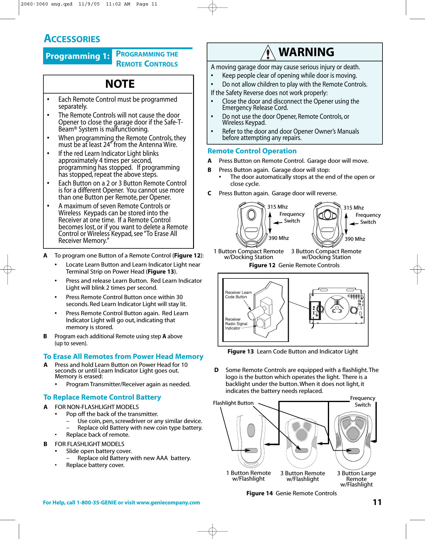
![For Help, call 1-800-35-GENIE or visit www.geniecompany.com 17Power Head Assembly[1]41FENB5C494239 4LMKHNJAD48GPRPARTS IDENTIFICATIONItem Part Name1 Power Head Assembly 1A Cover (by Series Model) 1BFront Plate Assembly 1C Light Socket 2D Motor Parts 1E Receiver Assembly 1F Capacitor (By Series/Model) 1G Opto Wheel 1H Opto-Luctor Assembly 1J Sequencer Assembly 1K Circuit Board Bracket 4LTransformer 1M Terminal Strip 1N No. 8-32 x 1/2" Hex Head Screww/Lockwasher 1P No. 8-32 x 3/8" Slot Hex Head Screw w/Lockwasher 1R Capacitor Isolator 14 1/4-20 Shoulder Bolt 251/4" Flange Nut 239 Coupler 141 No. 8-32 x 3/8" Phillips Hex Head Screw 442 No. 8-32 x 3/8" Phillips Pan Head Screw 248 Mounting Straps 249 Light Lens 1Power Head Parts ListPOWER HEADNumberIncluded2060-3060 eng.qxd 11/9/05 11:02 AM Page 17](https://usermanual.wiki/The-Genie-a-Division-of-Overhead-Door/315390R2/User-Guide-623841-Page-17.png)
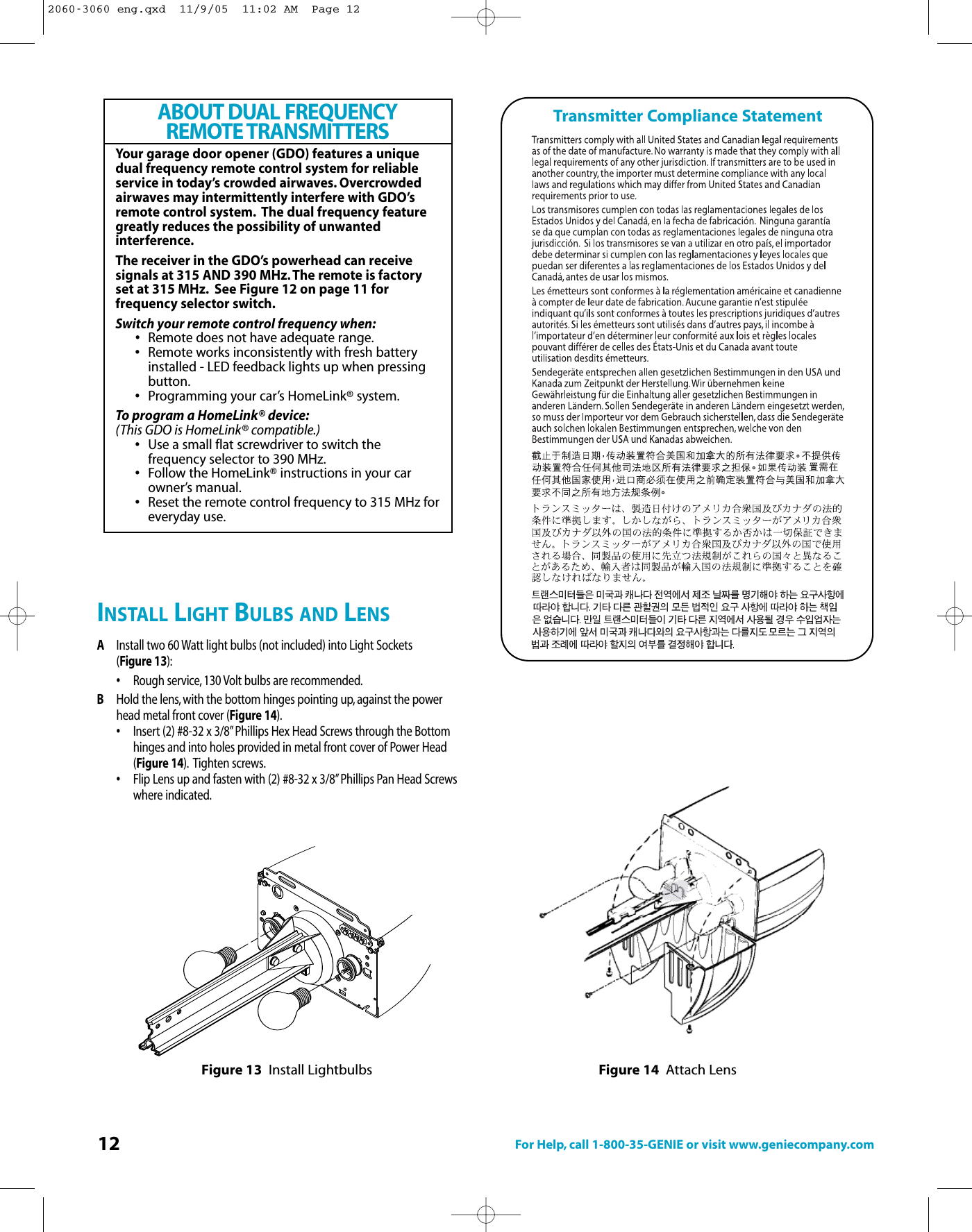
![18 For Help, call 1-800-35-GENIE or visit www.geniecompany.com15 B971216 61442292224282623910251718274615 A43954725248113A3B3C132021RAILPARTS IDENTIFICATIONItem Part Name1Power Head Assembly (see page 5) 13 Rail Assembly (3-piece) 13A First Rail Section 13B Middle Rail Section 13C End Rail Section 14 1/4”-20 Hex Head Shoulder Bolt 25 1/4”-20 Hex Flange Nut 26 Carriage Stop 17 Rail Clamps 48 5/16” Hex Head Shoulder Bolt 89 5/16” Hex Flange Nut 1310 Carriage Assembly 111 Collar 212 Retaining Clip 213 Rail Strap 115A Open Limit Switch Assembly (grey) 115B Close Limit Switch Assembly (brown) 116 #8-32 x 3/8” Hex Head Screw 217 Emergency Release Cord 118 Emergency Release Knob 119 Emergency Release Tag (not shown) 120 Header Bracket 121 Door Bracket 122 1/4” x 2” Lag Screw 823 Straight Door Arm 124 Clevis Pin 225 Cotter Pin 226 Curved Door Arm 127 3/8” x7/8” Hex Head Bolt 228 3/8” HexFlange Nut 2Parts List (cont’)NumberIncludedItem Part Name29 Wire (not shown) 95 ft30 Insulated Staples (not shown) 3031 Wall Button (not shown) varies33 Wall Console (not shown) varies34 #6 x 1-1/4” Pan Head Screw 235Entrapment WARNING Label (not shown)136 Safe-T-Beam (STB)Sensor (green LED)(not shown 137 Safe-T-Beam Source (red LED)(not shown) 138 Safe-T-Beam Bracket (not shown) 239 Coupler 140 #10 x 1-1/4” Phillips Hex Head Screw 441 #8 x 3/8” Hex Head Screw 442 #8 x 3/8” Pan Head Screw 243 Safety and Maintenance Guide (not shown) 144 Wire Clip 446 5/16” x3/4” Hex Head Bolt 547 1/4”-20 x 3/4” Self-tapping Screw 348 Mounting Straps 249 LightLens (see page 5) 150 Remote Control (not shown) variesNumber Included~~~~Parts List (cont’)Rail Assembly[3]2060-3060 eng.qxd 11/9/05 11:02 AM Page 18](https://usermanual.wiki/The-Genie-a-Division-of-Overhead-Door/315390R2/User-Guide-623841-Page-18.png)