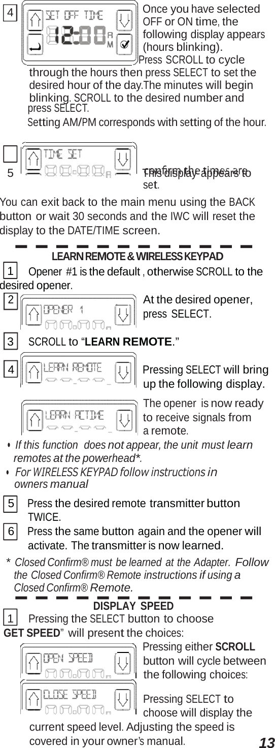
The Genie a Division of Overhead Door 915AW Advanced Wall Console Remote Control Transmitter User Manual

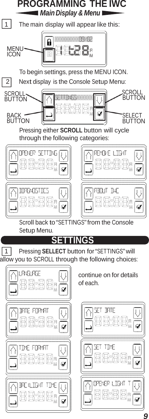
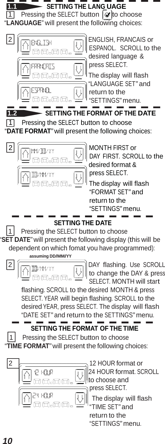
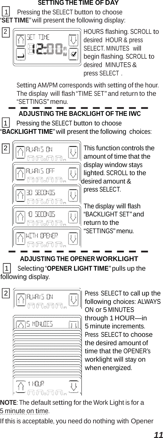
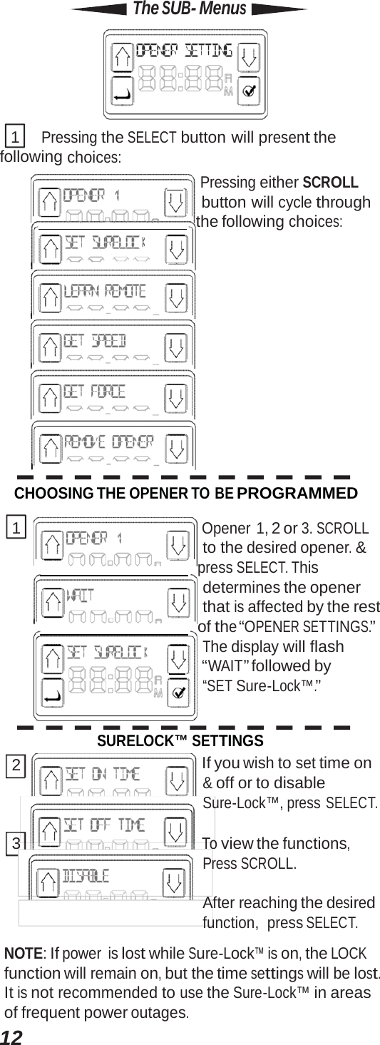
The Genie Company a Division of Overhead Door Corporation Advanced Wall Console Remote Control Transmitter

User manual

For Answers and Assistance: 1.800.354.3643 or visit www.geniecompany.com SAVE THIS MANUAL  FOR FUTURE REFERENCE. INSTALLER: LEAVE THIS MANUAL  WITH HOMEOWNER. Genie, Genie logo, Intellicode  & Safe-T-Beam are registered trademarks of GMI Holdings, Inc., dba The Genie Company. © The Genie  Company  2011  PN# 37380500131, 5/2012
Features •   Capable of operating 3 garage door openers and 3 door opener work lights. •   Time & Date are continuously displayed on the LCD screen. Time can be displayed in 12 or 24 hour s. Date can be displayed with DD/MM/YYYY or MM/DD/YYYY. •   Status messages are stored in a “histor e” that maintains the 10 most recent operations of the opener. •   Safe-T-Beam® system is continuously monitored— if their beam is obstructed, the Intelligent Wall Console (IWC) will display the message—“CHECK BEAMS.” •   Includes the SureLock™ security control— When activated, this prevents any remote or keypad operation of the opener. A great safety feature to have for peace of mind at night or while on vacation. •   Can be used to enable or disable the motion sensor on the opener’s powerhead (if so equipped). The motion sensor will detect movement inside the garage and turn on the opener’s work light. •   The name & phone number of your installer or local service company can be entered into the IWC. If a critical fault occurs during operation—a “call service” message will appear along with the name & number you have entered. •   Text can be displayed in English, Spanish or French. •   LCD display back light “ON” time can be user set to come on for a sp  period during use. •   The opener’s work light “ON” time can be user set to stay on for a sp period of time following the use of the work light button. •   Opener speed & force settings can be retrieved to c values during troubleshootiing or when determining if you want to make a change. •   A “Service Recommended” message will appear after a preset number of cycles. The number of recommended cycles can be adjusted by the installer. 2
3 Each opener that you wish to operate must be equipped with a Network Adapter in order to receive signals from the Intelligent Wall Console. In order to use the Intelligent Wall Console and Network Adapter equipment—your opener’s powerhead must wear this type of label— ATTENTION:Your garage door opener must have a Serial Number sticker that looks like this, in which the first two numbers are 10 or higher. MODEL AC SR3 THE GENIE COMPANY. FCC ID: B8Q  AC SR3 Residential Door Operator IC: 2133A-CSD1D 120V. 60HZ. 5A S/N:10XXXXXXXXXXXX FOR HELP CALL 1-800-275-6187 W WW.GENIECOMPANY.COM and must have a Network Adapter connection port (shown below). If you opener does not meet these criteria, you cannot use the Intelligent Wall Console. LEFT SIDE NETWORK ADAPTER PORT (must remove rubber cover) If you do not have a Network Adapter or need additional Adapters—contact your local Genie® Dealer. NOTE: If, at any time during programming, you receive the message ”NO NETWORK” on the display, check the following: •  Are power wires properly connected to terminals 5 & 6 on powerhead? •  Is the Adapter fully inserted and Green Light ON? •  Have you linked the IWC with the Adapter? (see pg. 8) WARNING Moving Door can cause serious injury or death. •  Wall Console must be mounted in sight of door, at least 5 feet above floor and clear of moving door parts. •  Keep people clear of opening while door is moving If Safety Reverse does not work properly: •   Do NOT allow children to play with Remote or door opener. If safety reverse does not work properly: •  Close door then disconnect opener using the manual release handle. •   Do NOT use remote or door opener . •  Refer to door & door opener owner manuals before trying any repairs.
4INSTALLATION (if needed) THE NETWORK ADAPTER ANTENNA WIRE CONNECTION PINS 1      Remove the Network Adapter from its packaging and insert it into the “NETWORK” port on the powerhead of your opener with the antenna wire facing down. GREEN LIGHT SHOULD TURN ON NETWORK BBU WARNING Do NOT place fingers, pliers, screw driver or any other device into the powerhead. 2 Straighten the antenna wire if needed so that it is THE INTELLIGENT WALL CONSOLE The Intelligent Wall Console receives its power through an opener powerhead (powered from only one opener for a group of up to three). •  Are power wires properly connected to terminals 5 & 6 on powerhead? 1      Using standard 2 conductor “bell wire,” Attach one end to the desired powerhead at terminals 5 & 6, as shown. TERMINALS LOCATED INSIDE LIGHT LENS Safe-T-Beam® Standard Wall Console INTELLIGENT WALL CONSOLE 1  2  3  4  5  6 STB BWC IWC NOTE: The IWC can be used in place of the basic wall console.
5 2 Route the wire from the chosen opener powerhead  (only one is required to be physically wired to the Console, for a group of up to 3 openers*) to the desired mounting location for the Console, being sure to keep it clear of any moving parts or equipment. Be sure to fasten it securely in place. If using insulated staples, be careful not to pinch or sever the wire. Make the staples only snug enough to hold the wire . 3 Mount the Console using the screws provided: A Unlatch and remove mounting backet. MOUNTING BRACKET LATCH B Remove the screws held in the back of the Console.  * In order to operate 2 or 3 garage door openers, you only need one IWC that is wired to the opener of your choice for power. (However, each opener MUST have its own Network Adapter.)
6C Attach the mounting bracket to the garage wall. D Attach wires to terminals on the back of the Console: E Attach the Console to the mounting bracket by sliding it down over the upper edge of the bracket and swinging it against the bracket until the latch engages. 1 2 3 IWC WALL MOUNTING BRACKET
7 FAMILIARIZATION   LCD DISPLAY WINDOW WIRE CHANNEL    POWER LED DATE TIME WIRE CHANNEL OPENER CONTROL  BUTTONS SURELOCK™ ICON/ INDICATOR MENU ICON      SCROLL BUTTON SELECT BUTTON WORK LIGHT CONTROL BUTTONS* * The Work Light Control buttons can be used to operate the opener’s Work Light, independently of operating the door opener. Work Lights can also be disabled during programming. See page 14. ** Sure-Lock™ can be activated by pressing and holding the Sure-Lock™ Icon/Indicator for 5 seconds, until the message “DOOR LOCKED” appears in the display window. To turn off Sure-Lock™, press and release the Icon.
8 LEARNING TO THE OPENER(S)   “NO NETWORK” will appear on the display if the unit is not correctly paired or wired with the Network Adapter. 1 PRESS &  RELEASE the button on the end of the Network Adapter. The GREEN LED will stay on while the BLUE LED flashes on and off. BLUE FLASHING GREEN     ON 2 PRESS &  RELEASE one of the Opener Control buttons on the IWC. The BLUE LED on the Network Adapter will go steady ON. BLUE ON GREEN ON 3 PRESS &  RELEASE the same Opener Control button again. The BLUE LED on the Network Adapter will turn OFF. BLUE OFF GREEN ON 4 PRESS &  RELEASE the same Opener Control button again and the opener will run—moving the door. REPEAT THESE SAME STEPS in order to program one of the other buttons to an additional opener. REMINDER: Additional openers must be equipped with a Network Adapter.
9PROGRAMMING THE IWC Main Display & Menu 1 The main  display will appear like this: MENU ICON To begin settings, press the MENU ICON. 2 Next display is the Console Setup Menu: SCROLL BUTTON      SCROLL BUTTON BACK BUTTON    SELECT BUTTON Pressing either SCROLL button will cycle through the following categories:  Scroll back to “SETTINGS” from the Console Setup Menu. SETTINGS 1 Pressing SELLECT button for “SETTINGS” will allow you to SCROLL through the following choices: continue on for details of each. 
101.1 SETTING THE LANG  UAGE 1 Pressing the SELECT button   to  choose “LANGUAGE” will present the following choices: 2 ENGLISH, FRANCAIS or ESPANOL.  SCROLL to the     desired language & press SELECT.      The display will flash      “LANGUAGE SET” and return to the “SETTINGS” menu. 1.2 SETTING THE FORMAT OF THE DATE 1 Pressing the SELECT button to choose “DATE FORMAT” will present the following choices: 2 MONTH FIRST or DAY FIRST. SCROLL to the     desired format & press SELECT.      The display will flash “FORMAT SET” and return to the “SETTINGS” menu. SETTING THE DATE 1 Pressing the SELECT button to choose “SET DATE” will present the following display (this will be dependent on which fomat you have programmed): assuming DD/MM/YY 2 DAY flashing. Use SCROLL to change the DAY & press SELECT. MONTH will start flashing. SCROLL to the desired MONTH & press SELECT. YEAR will begin flashing. SCROLL to the desired YEAR, press SELECT. The display will flash “DATE SET” and return to the SETTINGS” menu. SETTING THE FORMAT OF THE TIME 1 Pressing the SELECT button to choose “TIME FORMAT” will present the following choices: 2   12 HOUR format or 24 HOURformat.SCROLLto choose and press SELECT. The display will flash “TIMESET”andreturn to the “SETTINGS” menu.
11SETTING THE TIME OF DAY 1 Pressing the SELECT button to choose “SET TIME” will present the following display: 2         HOURS flashing. SCROLL to desired HOUR & press SELECT. MINUTES   will      begin flashing. SCROLL to desired  MINUTES & press SELECT . Setting AM/PM corresponds with setting of the hour. The display will flash “TIME SET” and return to the “SETTINGS” menu. ADJUSTING THE BACKLIGHT OF THE IWC 1 Pressing the SELECT button to choose “BACKLIGHT TIME” will present the following choices: 2 This function controls the amount of time that the      display window stays lighted. SCROLL to the     desired amount & press SELECT. The display will flash “BACKLIGHT SET” and return to the “SETTINGS” menu. ADJUSTING THE OPENER WORKLIGHT 1 Selecting “OPENER LIGHT TIME” pulls up the following display. 2 Press SELECT to call up the following choices: ALWAYS ON or 5 MINUTES       through 1 HOUR—in 5 minute increments. Press SELECT to choose the desired amount of time that the OPENER’s worklight will stay on when energized. NOTE: The default setting for the Work Light is for a 5 minute on time. If this is acceptable, you need do nothing with Opener
12Light Time.
12Off time  On time  same. The SUB- Menus  1 Pressing the SELECT button will present the following choices:      Pressing either SCROLL button will cycle through      the following choices: CHOOSING THE OPENER TO BE PROGRAMMED 1 Opener 1, 2 or 3. SCROLL to the desired opener. &     press SELECT. This determines the opener that is affected by the rest      of the “OPENER SETTINGS.” The display will flash      “WAIT” followed by “SET Sure-Lock™.” SURELOCK™ SETTINGS 2  If you wish to set time on & off or to disable Sure-Lock™, press SELECT. 3 To view the functions, Press SCROLL. After reaching the desired function, press SELECT. NOTE: If power is lost while Sure-Lock™ is on, the LOCK function will remain on, but the time settings will be lost. It is not recommended to use the Sure-Lock™ in areas of frequent power outages.
4 Once you have selected OFF or ON time, the following display appears (hours blinking).      Press SCROLL to cycle through the hours then press SELECT to set the desired hour of the day.The minutes will begin blinking. SCROLL to the desired number and press SELECT. Setting AM/PM corresponds with setting of the hour. 5      This display  appears to set. You can exit back to the main menu using the BACK button or wait 30 seconds and the IWC will reset the display to the DATE/TIME screen. LEARN REMOTE & WIRELESS KEYPAD 1 Opener #1 is the default , otherwise SCROLL to the desired opener. 2         At the desired opener, press SELECT. 3 SCROLL to “LEARN REMOTE.” 4 Pressing SELECT will bring up the following display. The opener  is now ready to receive signals from a remote. •  If this function  does not appear, the unit must learn remotes at the powerhead*. •   For WIRELESS KEYPAD follow instructions i n  owners manual 5 Press the desired remote transmitter button TWICE. 6 Press the same button again and the opener will activate. The transmitter is now learned. * Closed Confirm® must  be learned  at the Adapter. Follow the Closed Confirm® Remote instructions if using a Closed Confirm® Remote. DISPLAY SPEED 1 Pressing the SELECT button to choose GET SPEED” will present the choices:      Pressing either SCROLL button will cycle between    the following choices: Pressing SELECT to choose will display the current speed level. Adjusting the speed is covered in your owner’s manual. 13
14DISPLAY FORCE 1 Pressing the SELECT button to choose “GET FORCE” will present the choices:      Pressing either SCROLL button will cycle between    the following choices: Pressing SELECT to choose will display the current force level. Adjusting the force is covered in your owner’s manual. REMOVING  OPENER FROM AWC 1 Pressing the SELECT button to choose “REMOVE OPENER” will present the display:  1 Pressing the SELECT button will present the following choices: 2 Opener 1, 2 or 3. SCROLL       to the desired opener. &     press SELECT. “PLEASE WAIT” and return to the “SETTINGS” menu. NOTE: To return the light to operation, you must “REMOVE OPENER” (page 13) and then re-learn the opener (page 8). MOTION SENSOR ENABLE/DISABLE (for units so equipped). NOTE: After learning the Console to a Network Adapter, you can disable or enable that opener’s Motion Detector by pressing and holding it’s Work Light button for 10 seconds. Release the button and the Work Lights will flash twice confirming the desired action. •  On older units , the Work Lights will not flash to confirm the action, although the lights will be disabled or enabled.
 1 Pressing the SELECT button will present the following group of displays: 2 Using the SCROLL button to reach the desired function and press SELECT. STATUS RETRIEVAL 1 “CYCLE COUNT,”“MOTOR TEMP” and “MSG HISTORY” are displays of information  and have no user functionality. 2 Selecting CYCLE COUNT presents the following: OPENER 1, 2 or 3. SCROLL    to the desired opener. Pressing SELECT will display the number of cycles for that opener. 1 Selecting “MSG HISTORY” pulls up the 10 most recent operational events. example only 2 SCROLL through the list to view all. 1 Selecting “MOTOR TEMP” brings up the following display: OPENER 1, 2 or 3. SCROLL 2  to the desired opener.      Pressing SELECT will display the temperature       for that opener. 1 Pressing the SELECT button will present the following choices: 2        Installer Name, Installer Phone or Software Version. These are          simply displays of the existing        information.  Simply SCROLL through to retrieve the desired    information. Changing the Installer information is done under the Diagnostics menu. continued 15
ABOUT AWC continued RESETTING DEFAULT VALUES 1 Selecting “DELETE ALL” 2 Removes all openers from the IWC. SETTING SERVICE REMINDER 1 Selecting “SERVICE REMIND” pulls up the following display. SCROLL through the nine      digits to enter the number of cycles when you want to      be reminded to call for a    service check. When the opener reaches that total number of cycles, the display will remind you to call service and give you the phone number to call. CHANGING YOUR CONTACT 1 Selecting “CHANGE CONTACT” presents the following display:      To change  the  name press 2 SELECT and  SCROLL through each character to spell it out    or. press SCROLL first,  to shift to the CHANGE      NUMBER display. FCC & IC CERTIFIED This device complies with  part  15 of the FCC Rules and RSS 210 Industry Canada standard. Operation is subject to the following two conditions: (1) This device  may not  cause harmful interference,  and (2) this device must accept any interference received, including interference that may cause undesired operation.  This equipment generates, uses and can radiate  radio  frequency energy and, if not installed  and used in accordance  with  the instructions,  may cause harmful interference to radio communications. However, there is no guarantee that interference will not occur in a particular situation. If this equipment does cause harmful interference to radio or television reception, which may be determined  by turning  the equipment OFF and ON, the user is encouraged to try and correct the interference  by one or more of the following measures:  (a) Re-orient   or relocate  the  receiver  antenna,  (b) increase the separation between the opener and receiver, (c) Connect  the  opener  into  an outlet on a circuit  different   from  that  which  the receiver  is connected,  and (d) Consult your local dealer. Any modifications or changes to this equipment which  are not expressly approved by Overhead Door® Corp. could  void  the user’s authority  to operate the equipment. . 1 Door Drive, Mt. Hope, Ohio 44660 ©2012 The Genie Company
   (I NTELLIGENT C ONSOLE M Pour toutes questions et assistance : 1.800.275.6187 ou visitez notre site www.overheaddoor.com CONSERVER CE MANUEL À TITRE DE RÉFÉRENCE ULTÉRIEURE. INSTALLATEUR  : LAISSER CE MANUEL  AU PROPRIÉTAIRE DES LIEUX. Genie, Genie logo, Intellicode  & Safe-T-Beam et le logo Ribbon sont des marques déposées de Genie Company. © 2012 The Genie  Company   PN#  37381500131, 05/2012
DBA   ©2011 Caractéristiques •   Capable de faire fonctionner 3 ouvre-portes de garage et 3 lumières de l'ouvre-porte •   La date et l'heure sont toujours visibles à lʼécran LCD. L'heure peut s'afficher en format de 12 ou de 24 heures. La date peut être affichée en deux formats JJ/MM/AAAA ou MM/JJ/AAAA. •   Les messages de statuts sont enregistrés dans le fichier d'historique qui contient les 10 opérations les plus récentes de l'ouvre-porte. •   Le système Safe-T-Beam® est toujours sous surveillance. Si le faisceau est bloqué, la console Avancée Console Mural  (IWC) affiche le message BEAM BLOCKED. •   Inclut le système SureLock™ qui, si activé, empêche toute opération à distance (SureLock™peut être utilisé manuellement ou par minuterie). •   Peut être utilisée pour activer ou désactiver le capteur de mouvement sur la tête motorisée de l'ouvre-porte (si installée). Le capteur de mouvement détectera le mouvement à l'intérieur du garage et allumera la lumière de travail de l'ouvre-porte. •   Le nom et le numéro de téléphone de votre installateur ou de la société assurant le service localement peuvent être enregistrés dans l'IWC. Si une panne critique survient pendant le fonctionnement, un message « appeler le service » s'affiche avec le nom et le numéro que vous avez saisis. •   Le texte peut être affiché en anglais, en espagnol ou en français. La durée d'activation du rétroéclairage de l'affichage LCD peut être définie par l'utilisateur qui peut choisir entre activation continue, désactivation ou activation spécifique à un moment donné pendant l'utilisation. •   La durée d'activation de la lumière de l'ouvre-porte peut être définie par l'utilisateur pour que la lumière reste allumée pendant un certain temps après avoir utilisé le bouton de la lumière. •   Les réglages de force et de vitesse de l'ouvre-porte peuvent être affichés pour confirmer les valeurs pendant un dépannage ou pour déterminer si vous devez les changer. •   Un message Service recommandé s'affiche après un nombre prédéfini de cycles. Le nombre de cycles recommandés peut être réglé par l'installateur. 2
Les ouvre-portes que vous voulez utiliser doivent etre dotes d'un adaptateur de reseau pour pouvoir  recevoir les signaux emis par Ia Intelligent Console Murale. Pour pouvoir  utiliser  !'Intelligent  Console Murale ainsi que I'Adaptateur de reseau-ce type d'etiquette doit etre appose sur votre ouvre-porte- ATTENTIQN:un  auto-collant du type de celui-ci indiquant  un numero de serie dont les deux premiers chiffres sont 10 ou plus doit figurer sur votre ouvre- porte de garage. THE GENIE COMPANY Residential Door Operator 1 20V. 60HZ. SA 7     187WWW.GENIE   MPANY.   M et doivent  disposer d'un port  de connexion pour Adaptateur de reseau (illustration ci-dessous). Si votre ouvre-porte ne satisfait pas a ces criteres,vous ne pourrez pas utiliser Ia Intelligent Console Murale.  Si vous ne disposez pas d'Adaptateur  de reseau ou si vous avez besoin d'adaptateurs supplementaires-contactez votre revendeur OverheadDoor®. REMARQUE: si au cours de Ia programmation,le  message PAS DE RESEAU s'affiche,effectuez  les verifications suivantes: •   Les fils d'alimentation sont correctement connectes sur les bornes 5 et 6 de Ia tete motorisee? •  Est-ce que l'adaptateur est bien introduit? Le voyant vert estallume? •  Avez-vous relie I'IWC a l'adaptateur? (voir page 8) A AVERTISSEMENT Toute porte en mouvement peut entrainer de graves  blessures voire Ia mort. ·La console murale doit etre instaiiE§e en vue de Ia porte, a au moins 1,5 m au-dessus  du sol eta l'ecart des pieces mobiles de Ia porte. • Ne laisser personne dans l'encadrement de Ia porte pendant qu'elle est en mouvement. • Ne pas permettre aux enfants de jouer avec les telecommandes ou l'ouvre-porte. Si le systeme d'inversion ne fonctionne pas correctement, procedez com me suit : • Fermer d'abord Ia porte puis deconnecter I'ouvre-porte a I' aide de Ia poignee de declenchement manuel. • Ne pas utiliser   Ia telecommande  ni l'ouvre-porte. • Se reporter  aux  manuels de Ia porte  et de l'operateur de Ia  porte avant de tenter toute reparation. 3
console murale de base. INSTALLATION (si necessaire) L'ADAPTATEUR DE RESEAU ! L'INTELLIGENT CONSOLE MURALE Cette console est alimentee  par Ia tete motorisee de l'ouvre-porte (alimentee uniquement par un ouvre-porte). •  Les fils d'alimentation sont correctement connectes sur les bornes 5 et 6 de Ia tete motorisee? rTl   Avec until a cloche standard a deux conducteurs- ez l'extremite a Ia tete  motorisee  souhaitee  au niveau des bornes 5 et 6 (voir illustration). BORNES SITUEES DANS  LA LENTILLE DE LA LUMIERE  CD®@@  @@ STB BWC IWC REMARQUE:vous pouvez  utiliser  I'IWC a Ia place d'une
22 Acheminez le fil depuis la tête motorisée de l'ouvre-porte choisi (un seul ouvre-porte est requis pour le câblage vers la console d'un groupe de 3 ouvre-portes*) vers l'emplacement de l'installation de la console en vous assurant que l'acheminement est effectué à l'écart de pièces ou d'équipement mobiles. Assurez-vous que l'installation  est sécurisée. Si vous utilisez des agrafes isolées, prenez soin de ne pas pincer ni couper le fil.  Agrafez de manière à ce que le fil tienne en place sans exercer de force. 3 Installez la console à l'aide des vis fournies. A Déverrouillez et enlevez le support de fixation. SUPPORT DE FIXATION LOQUET B Enlevez les vis situées à l'arrière de la Console.  * Pour utiliser les ouvre-portes de garage 2 ou 3, vous n'avez besoin  que d'un IWC câblé  à l'ouvre-porte  de votre choix pour l'alimentation. (Toutefois, chaque ouvre-porte
console murale de base. DOIT disposer de son propre adaptateur de réseau).
2C Fixez le support de fixation au mur du garage. D Fixez les fils aux bornes à l'arrière de la console : E Fixez la console  au support de fixation en la glissant vers le bas par dessus le bord supérieur de support et en la pivotant contre le support jusqu'à ce que  le loquet s'engage. 1 2  3 IWC MUR SUPPORT

Navigation menu