The Genie a Division of Overhead Door 915AW Advanced Wall Console Remote Control Transmitter User Manual
The Genie Company a Division of Overhead Door Corporation Advanced Wall Console Remote Control Transmitter
User manual

For
Answers and Assistance:
1.800.354.3643
or visit www.geniecompany.com
SAVE THIS MANUAL
FOR FUTURE REFERENCE.
INSTALLER: LEAVE THIS
MANUAL WITH HOMEOWNER.
Genie, Genie logo, Intellicode
&
Safe-T-Beam
are registered trademarks
of GMI Holdings, Inc., dba The Genie Company.
©
The Genie Company 2011 PN# 37380500131, 5/2012
F
e
a
t
u
r
e
s
•
C
a
p
a
b
l
e
o
f
operating
3
ga
r
ag
e
d
oo
r
openers
and
3
d
oo
r
opener
w
o
r
k
li
g
h
t
s
.
•
Time
&
Date
are
c
o
n
t
i
n
u
o
u
s
l
y
d
i
s
p
l
a
y
e
d
o
n
t
h
e
LCD
s
c
r
ee
n
.
Time
c
a
n
be
d
i
s
p
l
a
y
e
d
i
n
12
o
r
24
h
o
u
r
s
.
Date
c
a
n
b
e
d
i
s
p
l
a
y
e
d
with
DD
/
MM
/
YYYY
o
r
MM
/
DD
/
YYYY
.
•
S
t
a
t
u
s
m
e
ss
ag
e
s
a
r
e
s
t
o
r
e
d
i
n
a
“
h
i
s
t
o
r
e
”
that
m
a
i
n
t
a
i
n
s
t
h
e
10
m
o
s
t
r
e
c
e
n
t
o
p
e
r
a
t
i
o
n
s
o
f
t
h
e
o
p
e
n
e
r
.
•
S
a
f
e
-
T
-
B
e
a
m
®
s
y
s
t
e
m
i
s
c
o
n
t
i
n
u
o
u
s
l
y
m
o
n
i
t
o
r
e
d
—
i
f
t
h
e
i
r
beam
i
s
o
b
s
t
r
u
c
t
e
d
,
t
h
e
Intelligent
W
a
ll
C
o
n
s
o
l
e
(
I
W
C
)
w
ill
d
i
s
p
l
a
y
t
h
e
m
e
ss
ag
e
—
“
C
H
E
CK
B
E
A
M
S
.
”
•
I
n
c
l
ud
e
s
t
h
e
SureLock™
s
e
c
u
r
i
t
y
c
o
n
t
r
o
l
—
When
a
c
t
i
v
a
t
e
d
,
t
h
i
s
p
r
e
v
e
n
t
s
any remote
o
r
k
e
y
p
a
d
operation
of
the
opener.
A
great
safety
feature
to
have
for
peace
of
mind
at
night
or
while
on
vacation.
•
C
a
n
b
e
u
s
e
d
t
o
enable
o
r
disable
t
h
e
m
o
t
i
o
n
sensor
on
t
h
e
opener’s powerhead
(
i
f
s
o
equipped).
T
h
e
motion
sensor
w
ill
d
e
t
e
c
t
movement
i
n
s
i
d
e
t
h
e
garage
and
t
u
rn
o
n
t
h
e
opener’s
w
o
r
k
li
g
h
t
.
•
T
h
e
name
&
p
h
o
n
e
number
o
f
y
o
u
r
i
n
s
t
a
ll
e
r
o
r
l
o
c
a
l
service c
o
m
p
a
n
y
c
a
n
b
e
e
n
t
e
r
e
d
i
n
t
o
t
h
e
I
W
C
.
I
f
a
critical
f
a
u
l
t
occurs
during operation—a “call
s
e
r
v
i
c
e
”
message
w
ill
appear
a
l
o
n
g
with
t
h
e
name
&
n
u
m
b
e
r
y
o
u
have
e
n
t
e
r
e
d
.
•
T
e
x
t
c
a
n
b
e
d
i
s
p
l
a
y
e
d
i
n
E
n
g
li
s
h
,
S
p
a
n
i
s
h
o
r
F
r
e
n
c
h
.
•
LCD
d
i
s
p
l
a
y
back
li
g
h
t
“ON”
t
i
m
e
c
a
n
b
e
user
s
e
t
to
come
o
n
f
o
r
a
sp
p
e
r
i
o
d
during u
s
e
.
•
T
h
e
opener’s
w
o
r
k
li
g
h
t
“ON”
t
i
m
e
c
a
n
b
e
user
s
e
t
to
s
t
a
y
o
n
f
o
r
a
sp
p
e
r
i
o
d
o
f
t
i
m
e
following
the
use
of
the
work
light
button.
•
O
p
e
n
e
r
speed
&
f
o
r
c
e
s
e
tt
i
n
g
s
c
a
n
b
e
r
e
t
r
i
e
v
e
d
to
c
v
a
l
u
e
s
during
t
r
o
ub
l
e
s
h
oo
t
ii
n
g
o
r
w
h
e
n
determining
i
f
y
o
u
want
t
o
make
a
c
h
a
n
g
e
.
•
A
“
S
e
r
v
i
c
e
R
e
c
o
mm
e
n
d
e
d
”
message
w
ill
a
pp
e
a
r
a
f
t
e
r
a
p
r
e
s
e
t
number
o
f
c
y
c
l
e
s
.
T
h
e
number
o
f
r
e
c
o
mm
e
n
d
e
d
c
y
c
l
e
s
c
a
n
b
e
a
d
j
u
s
t
e
d
b
y
t
h
e
i
n
s
t
a
ll
e
r
.
2
3
Each opener
that you
wish
to
operate
must be
equipped with
a Network Adapter
in
order
to receive
signals
from the Intelligent
Wall
Console.
In
order
to
use
the Intelligent
Wall Console
and
Network Adapter
equipment—your
opener’s
powerhead
must
wear
this type of label—
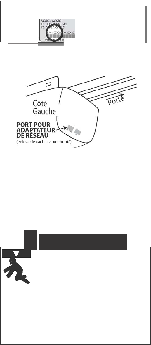
ATTENTION:
Your garage door opener
m
u
s
t
h
ave
a
S
e
ri
a
l
Number
s
t
i
c
k
e
r
that looks like
t
h
i
s
,
i
n
which
t
h
e
f
ir
s
t
t
w
o
nu
m
b
e
r
s
a
r
e
10
o
r
h
i
gh
e
r
.
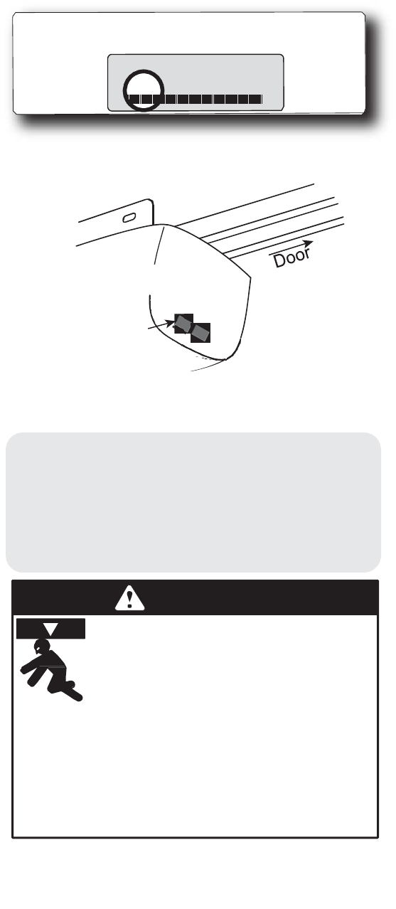
MODEL AC SR3
THE GENIE
COMPANY.
FCC ID: B8Q AC SR3
Residential Door
Operator
IC:
2133A-CSD1D
120V. 60HZ.
5A
S/N:10XXXXXXXXXXXX
FOR HELP CALL
1-800-275-6187 W
WW.GENIECOMPANY.COM
and
must
have a Network Adapter connection
po
r
t
(shown below).
If you
opener does
not meet these
c
r
i
t
e
r
ia,
you
cannot
use
the Intelligent
Wall Console.
LEFT
SIDE
N
E
T
W
ORK
ADAPTER PORT
(must remove rubber cover)
If you do not
have a Network Adapter
or need
additional
Adapters—contact
your
local Genie®
Dealer.
NOTE
: If,
at
any
time during
p
r
o
g
r
a
mm
i
n
g
,
you
receive
the
message ”NO N
E
T
W
O
R
K
”
on the
d
i
s
p
l
a
y
,
check
the
f
o
ll
o
w
i
n
g
:
•
Are power wires properly connected
to
t
e
r
m
i
n
a
l
s
5
&
6
on
p
o
w
e
r
h
ea
d
?
•
Is
the
Adapter
fully
i
n
s
e
r
t
e
d
and Green
Light
O
N
?
•
Have you linked
the
IWC
with the
A
d
a
p
t
e
r
?
(see
p
g
.
8)
WARNING
Moving Door can cause serious
injury
or death.
•
Wall Console
must be mounted in sight
of
doo
r
,
at
least
5 feet
above
floor and
clear
of moving door
pa
r
t
s
.
•
Keep people clear
of opening while
door
is
moving
If
Safety Reverse does
not
work
properly:
•
Do
NOT
allow children to play with
Remote
or door opener.
If
s
a
fety
reverse
does
not work properl
y
:
•
Close door
then
disconnect opener
using the manual
release
handle.
•
Do
NOT
use
remote or door
opene
r
.
•
Refer
to door
&
door
opener
owner
manuals before
trying
any
repairs.
4
INSTALLATION (if
needed)
THE NETWORK
ADAPTER
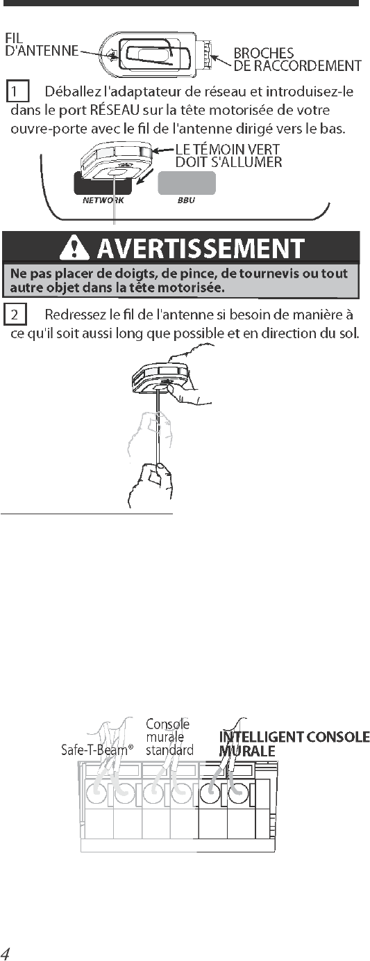
A
N
T
E
NN
A
W
I
RE
C
O
NN
E
C
T
I
O
N
P
I
N
S
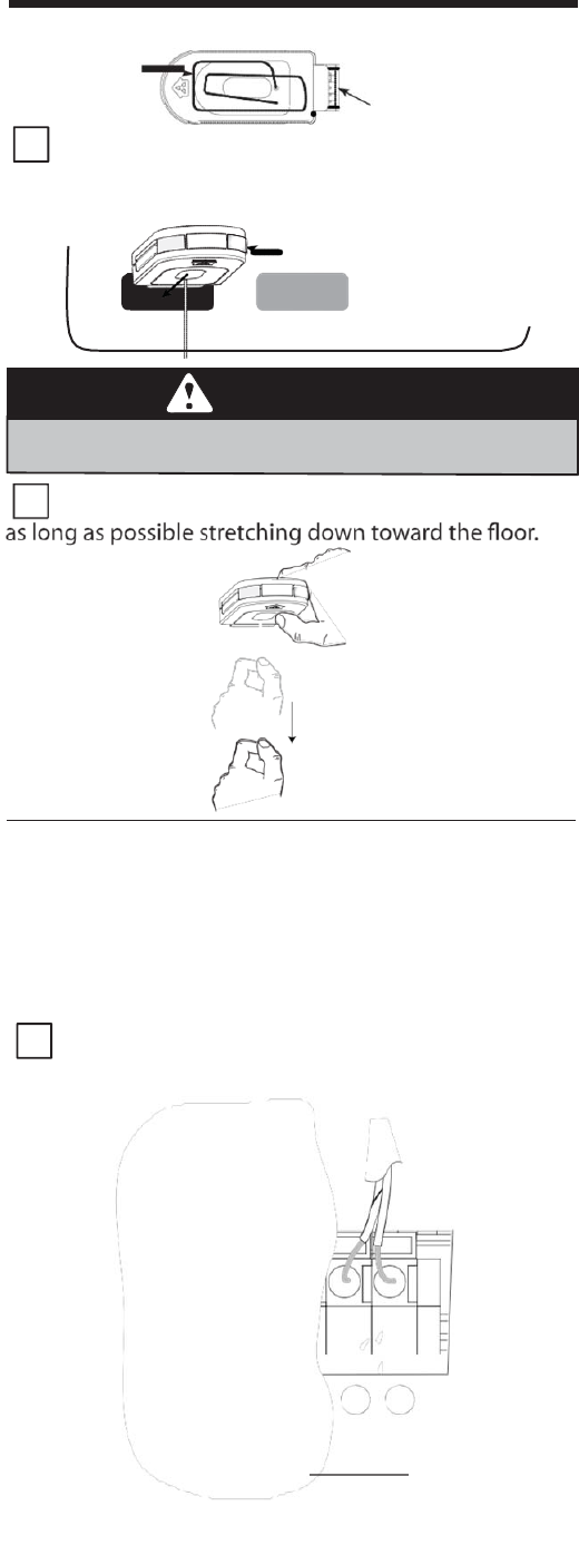
1
R
em
o
v
e
the
Network Adapter
from its packaging
and
i
n
s
e
r
t
it into
t
h
e
“
N
E
T
WO
R
K
”
port on the powerhead
of
your opener
with the
a
n
t
e
nn
a
wire
facing
d
o
w
n
.
GREEN
LIGHT
SHOULD TURN
ON
NETWORK BBU
WARNING
Do NOT place fingers,
plier
s
,
screw
dri
ve
r
o
r
any
other device
into the powerhead.
2
S
t
r
a
i
g
h
t
e
n the
a
n
t
e
nn
a
wire if
needed so
that it
i
s
THE INTELLIGENT WALL CONSOLE
The
I
n
t
e
lli
g
e
n
t
Wall Console receives
its power
through
an opener powerhead
(powered from
only
one opener for
a
group of up to
thr
e
e)
.
•
Are power wires p
roperly connected
to
t
e
r
m
i
n
a
l
s
5
&
6
on
p
o
w
e
r
h
ea
d
?
1
Using standard
2
c
ondu
c
t
or
“bell
wi
r
e
,
”
Attach
one end
to the
desired powerhead
at
terminals
5
&
6,
as
shown.
TERMINALS LOCATED INSIDE LIGHT
L
E
N
S
S
a
f
e
-
T
-
B
e
a
m
®
S
t
a
n
d
a
r
d
Wall
C
on
s
o
l
e
I
N
T
E
LL
I
G
E
N
T
WALL
C
O
N
S
O
L
E
1 2 3 4 5
6
STB
BWC
IWC
NOTE
: The
IWC
can be used in place of
the
basic
wall
c
o
n
s
o
l
e
.
5
2
R
out
e
the wire from the
chosen
opener
powerhead (only one
is required
to
be physically wired
t
o
the Console, for a group of up
to
3 openers*)
to the
d
e
s
i
r
e
d
mounting
location
for the
Console,
being
sure
to
keep
it
clear
of
any
moving
parts
or
equipmen
t
.
Be sure
to
fasten
it
securely
in
plac
e
.
If
using
insulated
s
t
a
p
l
e
s
,
be careful not
to
pinch or sever
the
w
i
r
e
.
Make
the
staples
only
snug enough
to hold the wire
.
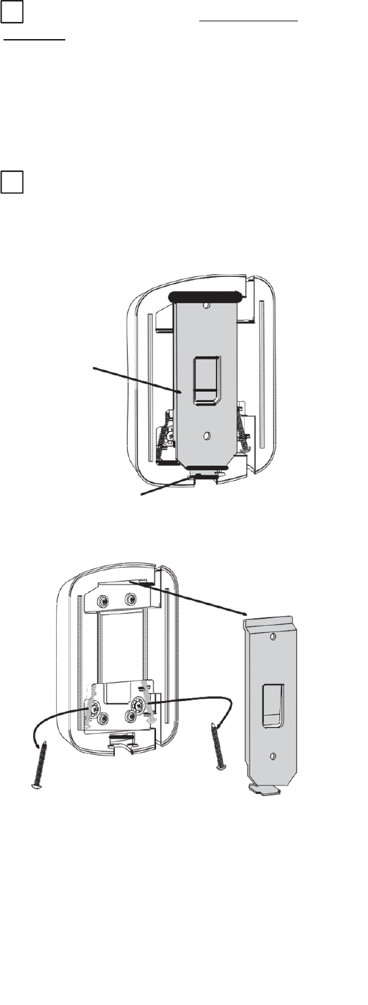
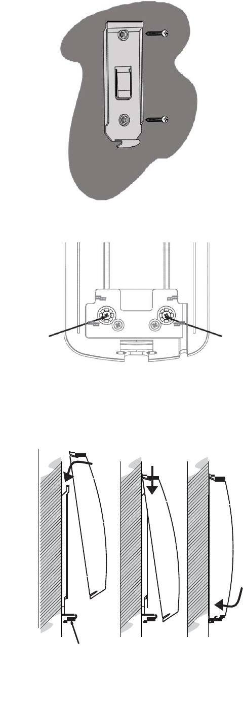
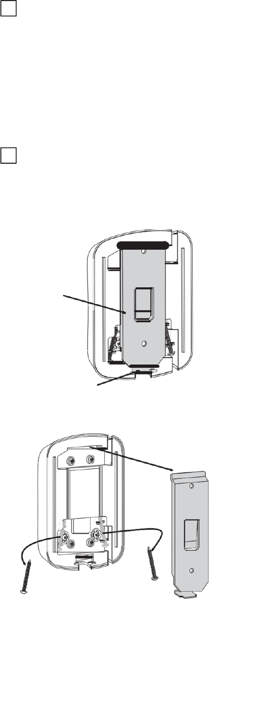
3 Mount the
Console using
the
screws
provided:
A
Unlatch and remove
mounting
b
a
c
k
e
t
.
M
OU
N
T
I
N
G
B
RA
C
K
E
T
L
A
T
C
H
B
R
e
m
o
v
e
the
screws
held in the
back
of
the
C
o
n
s
o
l
e
.
* In
order
to
operate
2 or 3
garage
door
openers
,
you
only
need one IWC
that
is
wired to the
opener
of your
choice
for
po
w
er
.
(However, each opener MUST have
its
own Network
A
dapt
er
.)
6
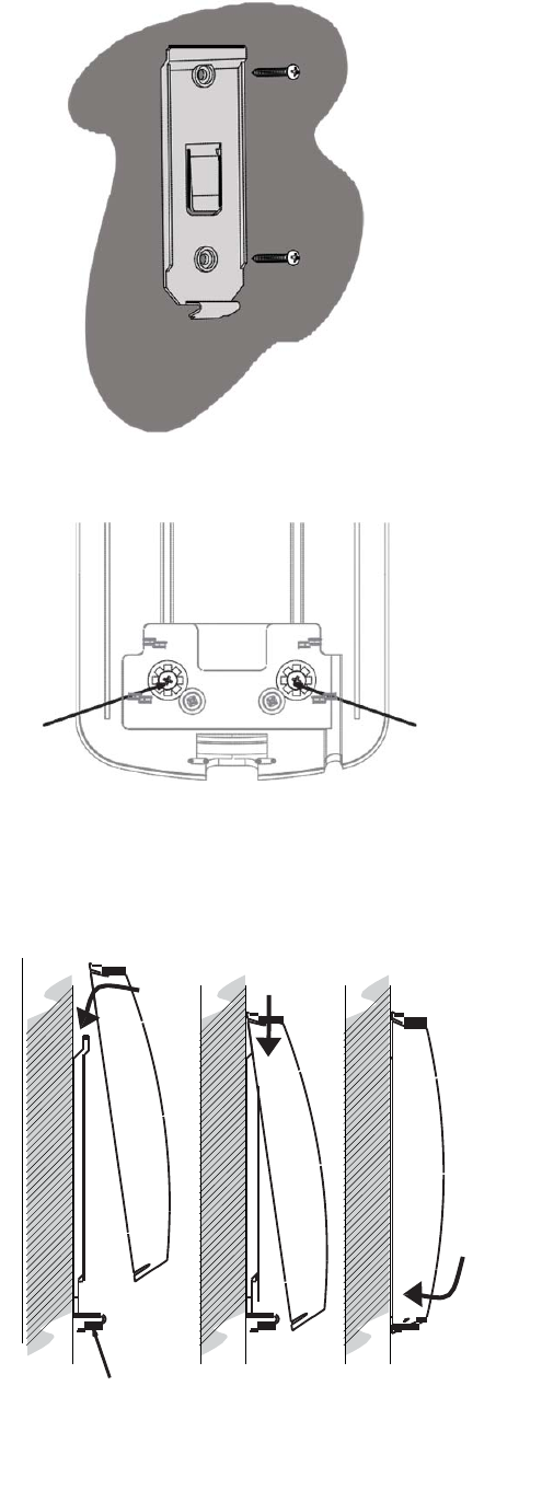
C
Attach
the mounting
b
r
a
c
k
e
t
to the
garage
w
a
ll
.
D
Attach
wires
to
t
e
r
m
i
n
a
l
s
on the
back
of
the
C
o
n
s
o
l
e
:
E
Attach
the
Console
to the mounting
b
r
a
c
k
e
t
by
s
li
d
i
n
g
it down
over
the
upper edge
of the
b
r
a
c
k
e
t
and
s
w
i
n
g
i
n
g
it
a
g
a
i
n
s
t
the bracket
until the
latch
e
n
g
a
g
e
s
.
1 2 3
I
W
C
WALL
M
OU
N
T
I
N
G
B
RA
C
K
E
T
7
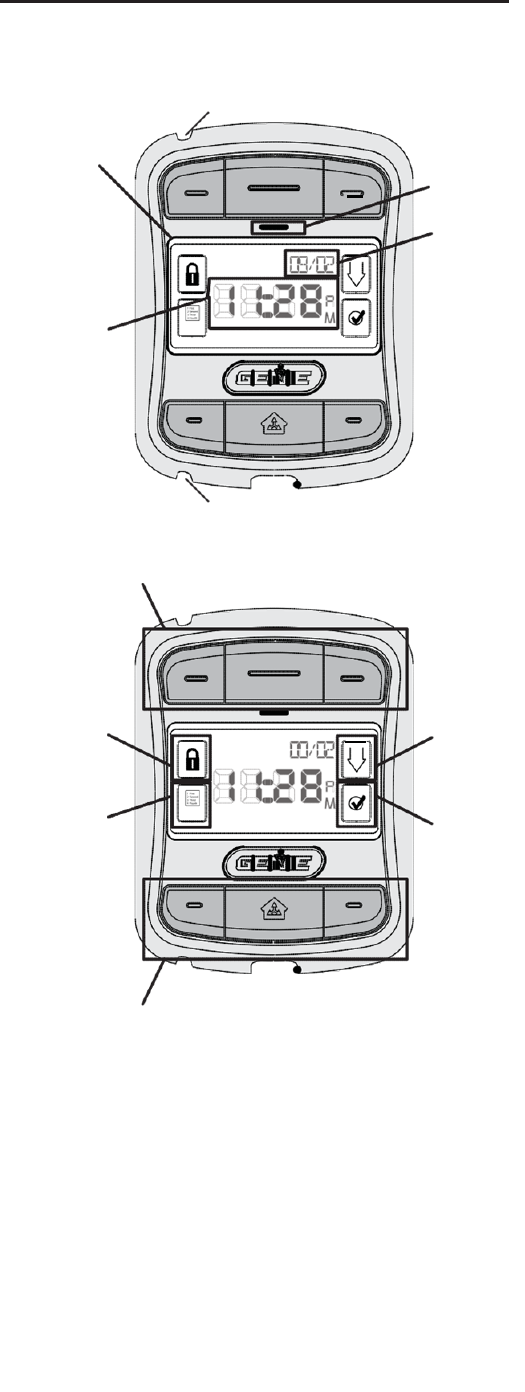
F
AMILIARIZ
A
TION
L
C
D
D
I
S
P
L
A
Y
W
I
N
D
OW
WIRE
C
H
A
NN
E
L
P
OW
ER
L
E
D
DA
T
E
T
I
M
E
WIRE
C
H
A
NN
E
L
OPENER CONTROL B
U
TT
O
N
S
S
U
RE
L
O
C
K
™
I
C
O
N
/
I
N
D
I
C
A
T
O
R
M
E
N
U
I
C
O
N
S
C
R
O
LL
B
U
TT
O
N
SE
L
E
C
T
B
U
TT
O
N
WORK LIGHT CONTROL
B
U
TT
O
N
S
*
*
The Work
Light
Control
b
u
tt
o
n
s
can be used
to operate
the
opener’s Work
L
i
g
h
t
,
independently
of
operating
the
door
o
p
e
n
e
r
.
Work
L
i
g
h
t
s
can also be
d
i
s
a
b
l
e
d
d
u
r
i
n
g
p
r
o
g
r
a
mm
i
n
g
.
See page
14
.
**
S
u
r
e
-
L
o
c
k
™
can
be activated
by
pressing and h
o
l
d
i
n
g
the
S
u
r
e
-
L
o
c
k
™
I
c
o
n
/
I
n
d
i
c
a
t
o
r
for
5
s
ec
o
n
d
s
,
until the
m
e
ss
a
g
e
“DOOR
L
O
C
K
E
D
”
appears
in the
display
w
i
n
d
o
w
.
To
turn off
S
u
r
e
-
L
o
c
k
™
,
press and release
the
I
c
o
n
.
8
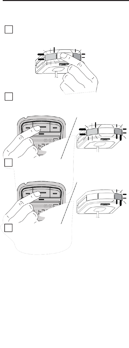
LEARNING
T
O
THE
OP
ENER(S)
“
N
O
NETWORK
”
w
ill
appear
o
n
t
h
e
d
i
s
p
l
a
y
i
f
t
h
e
u
n
i
t
i
s
n
o
t
c
o
rr
e
c
t
l
y
pa
i
r
e
d
o
r
wired
w
i
t
h
t
h
e
N
e
t
w
o
r
k
A
dap
t
e
r
.
1
PRESS & RELEASE
the button on the
end
of the
Network
A
dapt
er
.
The GREEN LED
will
s
t
a
y
on while the
BLUE LED
flashes
on
and
o
ff
.
B
L
U
E
F
L
A
S
H
I
N
G
G
R
EE
N
ON
2
PRESS & RELEASE
one
of the
Opener
C
o
n
t
r
o
l
b
u
tt
o
n
s
on the
I
W
C
.
The BLUE LED
on the Network
Adapter
will go
s
t
e
a
d
y
O
N
.
B
L
U
E
ON
G
R
EE
N
ON
3
PRESS & RELEASE
the
same Opener
C
o
n
t
r
o
l
button
a
g
a
i
n
.
The BLUE LED
on the
Network Adapter
w
ill
turn
O
FF
.
B
L
U
E
O
FF
G
R
EE
N
ON
4
PRESS & RELEASE
the
same Opener
C
o
n
t
r
o
l
button
again and
the
opener
will run—moving the
d
oo
r
.
R
E
P
E
AT
T
H
E
S
E
S
A
M
E
S
T
E
P
S
i
n
o
r
d
e
r
t
o
p
r
o
g
r
a
m
o
n
e
o
f
t
h
e
o
t
h
e
r
bu
tt
o
n
s
t
o
a
n
a
dd
i
t
i
o
n
a
l
o
p
e
n
e
r
.
R
E
MI
N
D
E
R
:
A
dd
i
t
i
o
n
a
l
op
e
n
e
r
s
m
u
s
t
b
e
equipped
w
i
t
h
a
N
e
t
w
o
r
k
A
dap
t
e
r
.
9
PROGRAMMING THE
IWC
M
a
i
n
Display
&
M
e
nu
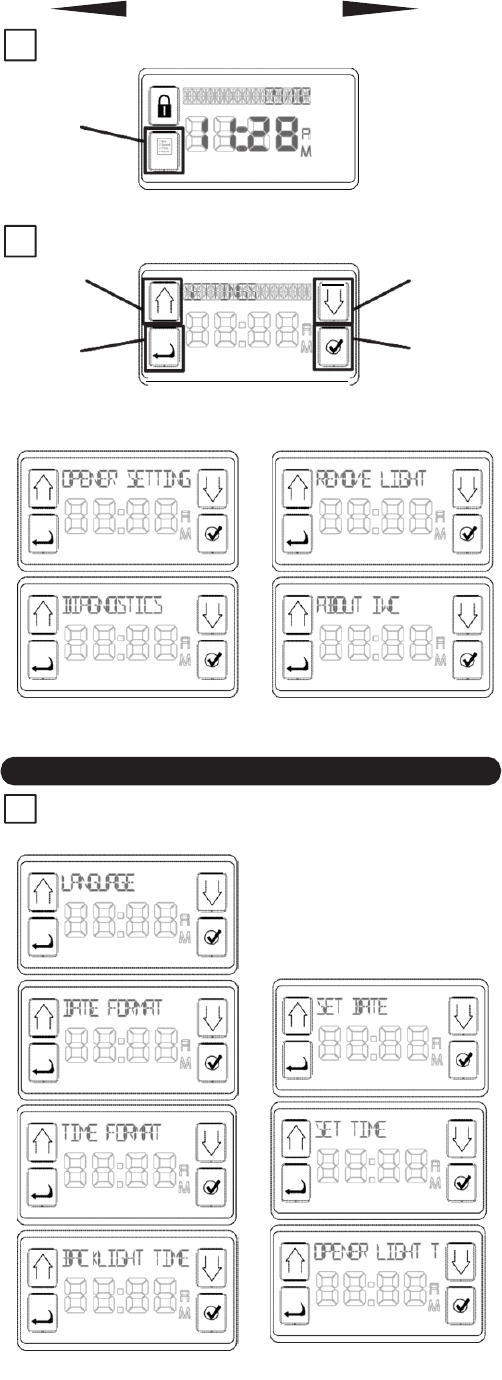
1
The main display
will
appear like
this:
M
E
N
U
I
C
O
N
To
begin
settings
,
press
the
MENU
IC
ON.
2
N
e
x
t
display is
the
Console
S
e
t
u
p
M
e
n
u
:
S
C
R
O
LL
B
U
TT
O
N
S
C
R
O
LL
B
U
TT
O
N
B
A
C
K
B
U
TT
O
N
SE
L
E
C
T
B
U
TT
O
N
Pressing
either
SCROLL
button will cycle
through the following
c
a
t
e
g
o
r
i
e
s
:
S
c
r
o
ll
back
t
o
“
SE
TT
I
N
G
S
”
from the
C
o
n
s
o
l
e
S
e
t
u
p
M
e
n
u
.
SETTINGS
1
Pressing
SELLECT
button
f
o
r
“
SE
TT
I
N
G
S
”
w
i
ll
allow you
to
SCROLL
through the following
c
h
o
i
ce
s
:
continue
on for
d
e
t
a
il
s
of
e
a
c
h
.
1
0
1.1
SET
TING
THE LANG
UAGE
1
Pressing
the
SELECT
button to choose
“
LANGUAGE
”
will
pr
esen
t
the following
choic
es:
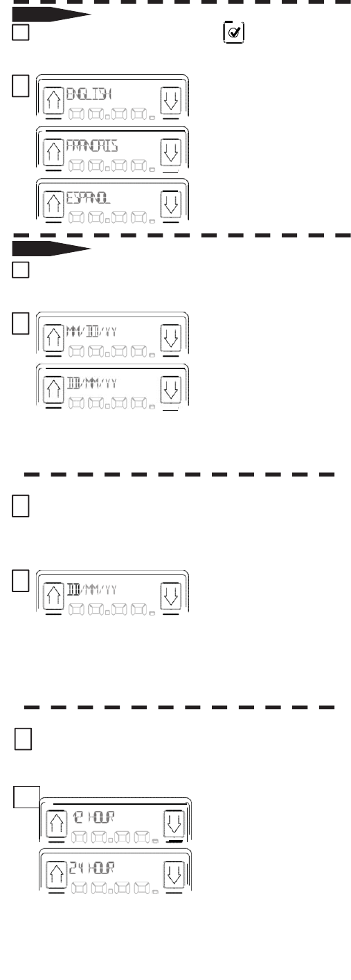
2
ENGLISH, FRANCAIS
or
ESPANOL. SCROLL
to the
desired language &
press
SELEC
T
.
The display
will flash
“LANGUAGE
SE
T
”
and
return to the
“SE
T
TINGS
”
menu
.
1.2
SET
TING
THE FORMAT
OF
THE
DATE
1
Pressing
the
SELECT
button to choose
“
DATE FORMA
T
”
will
pr
esen
t
the following
choic
es:
2
MONTH
FIRST
or
DAY FIRST. SCROLL
to the
desired
format
&
press
SELEC
T
.
The display
will flash
“FORMAT
SE
T
”
and
return to the
“SE
T
TINGS
”
menu
.
SET
TING
THE
DA
TE
1
Pressing
the
SELECT
button to
c
h
oo
s
e
“
SET
D
A
T
E
”
will
p
r
e
s
e
n
t
the following
display
(
t
h
i
s
w
ill
b
e
dependent
on
which fomat you
have
p
r
o
g
r
a
mm
e
d
)
:
assuming DD
/
MM
/
YY
2
DAY
fl
a
s
h
i
n
g
.
Use
S
C
R
O
LL
to
change
the
DAY &
p
r
e
ss
SELECT.
MONTH
will
s
t
a
r
t
fl
a
s
h
i
n
g
.
SCROLL
to the
desired MONTH &
p
r
e
ss
SELECT. YEAR
will
begin
fl
a
s
h
i
n
g
.
SCROLL
to the
d
e
s
i
r
e
d
YEAR,
press
SELECT.
The display
will flash
“DATE
SE
T
”
and
return to the
SE
T
TINGS
”
menu
.
SET
TING
THE FORMAT
OF
THE
TIME
1
Pressing
the
SELECT
button to
c
h
oo
s
e
“
TIME
F
O
R
M
A
T
”
will
p
r
e
s
e
n
t
the following
c
h
o
i
ce
s
:
2
12 HOUR
format
or
24 HOUR
f
o
r
m
a
t
.
S
C
R
O
LL
to
choose
and
press
SE
L
E
C
T
.
The display
will flash
“TIME
SE
T
”
and
return to the
“SE
T
TINGS
”
menu
.
11
SET
TING
THE
TIME OF
DAY
1
Pressing
the
SELECT
button to
c
h
oo
s
e
“
SET
T
I
M
E
”
will
p
r
e
s
e
n
t
the following
d
i
s
p
l
a
y
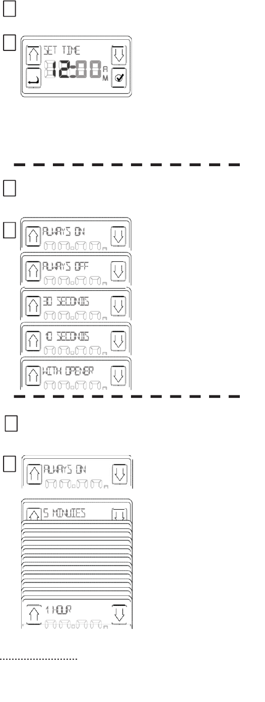
:
2
HOURS
fl
a
s
h
i
n
g
.
SCROLL
t
o
desired HOUR & p
r
e
ss
SELECT. MINUTES w
i
ll
begin
fl
a
s
h
i
n
g
.
SCROLL
t
o
desired MINUTES
&
press
SELECT .
S
e
tt
i
n
g
A
M
/
P
M
corresponds
with
s
e
tt
i
n
g
of
the h
our
.
The display
will
flash
“TIME
SE
T
”
and
return to the
“SE
T
TINGS
”
menu
.
ADJUSTING
THE BACKLIGHT
OF
THE
IW
C
1
Pressing
the
SELECT
button to
c
h
oo
s
e
“
B
A
C
KL
I
G
H
T
T
I
M
E
”
will
p
r
e
s
e
n
t
the following
c
h
o
i
ce
s
:
2
This
function
c
o
n
t
r
o
l
s
the
amount
of time that the
display
window
s
t
a
y
s
li
g
h
t
e
d
.
SCROLL
to the
desired
amount
&
press
SE
L
E
C
T
.
The display
will
fl
a
s
h
“BACKLIGHT
SE
T
”
and
return
to the
“
SE
TT
I
N
G
S
”
m
e
n
u
.
ADJUSTING
THE
OPENER
WORKLIGHT
1
S
elec
ting
“
OPENER
LIGHT
TIME
”
pulls
up the
following
display
.
2
Press SELECT
to
call
up
the
following
choic
es:
ALWAYS
ON
or 5
MINUTES
through 1 HOUR—in
5 minute
incr
emen
ts
.
Press SELECT
to choose
the
desired
amount
of
time that the
OPENER
’
s
worklight will
stay
on
when
ener
g
iz
ed
.
N
O
T
E
:
The
default
s
e
tt
i
n
g
for
the
Work
Light
is
for a
5
minute on
t
i
m
e
.
If
t
h
i
s
is a
cce
p
t
a
b
l
e
,
you need
do nothing with Opener
1
2
Light
T
i
m
e
.
1
2
Off time On time same.
T
h
e
S
U
B
-
M
e
nu
s
1
Pressing
the
SELECT
button will
pr
esen
t
the
following
choic
es:
Pressing
either
S
CR
O
LL
button will
cycle
t
h
r
ou
g
h
the following
c
h
o
i
ce
s
:
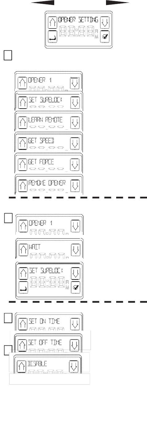
CHOOSING
THE
OPENER
TO BE
PROGRAMMED
1
Opener 1,
2 or
3.
SCR
OLL
to the
desired
opener
.
&
press
SELECT.
T
his
det
er
mines
the opener
that
is
affected
by the rest
of
t
h
e
“
O
P
E
N
ER
SE
TT
I
N
G
S.
”
T
he
display
will flash
“
W
AIT
”
followed by
“SET
Sur
e
-L
ock™
.
”
SURELOCK™
SET
TINGS
2 If you
wish
to
set
time on
&
off or to disable
Sure-Lock™, press
SELEC
T
.
3
To
view the
functions
,
Press
SCR
OLL.
After reaching
the
d
e
s
i
r
e
d
function, press
SELEC
T
.
NOTE
:
If
power is
l
o
s
t
while
S
u
r
e
-
L
o
c
k
™
is
o
n
,
the
L
O
CK
function will
remain
o
n
,
but the time
s
e
tt
i
n
g
s
will
be
l
o
s
t
.
It
is
not
recommended
to
use
the
Sure-Lock™
in areas
of
frequent
power
outages
.
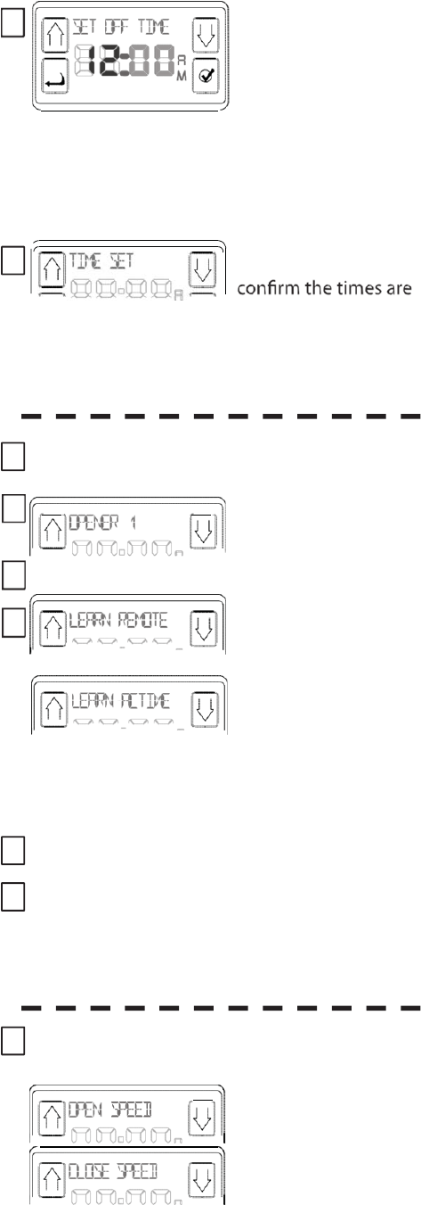
4
Once
you
have
selected
OFF
or
ON
tim
e
,
the
following
display
a
pp
e
a
r
s
(hours
blinking).
Press SCROLL
to cycle
th
r
ough the
hours
then
press
SELECT
to
set
the
desired
hour of the
d
a
y
.
T
he
minutes
will begin
blin
k
in
g
.
SCROLL
to the
desired
number and
press
SELE
C
T
.
S
e
tt
i
n
g
A
M
/
P
M
corresponds
with
s
e
tt
i
n
g
of the hou
r
.
5
This display appears
to
se
t
.
You can
exit
back
to the
main menu using
the
B
A
CK
button or wait
30 seconds and
the
IWC
will
reset
the
display
to the
DATE/TIME
screen.
L
E
A
R
N
R
E
M
O
T
E
&
W
I
R
E
L
E
SS
K
E
Y
P
A
D
1
Opener #1 is
the
default
,
o
t
h
e
r
w
i
s
e
SCROLL
to the
desired
o
p
e
n
e
r
.
2
At the
desired
opener,
press SELECT.
3
SCROLL
to
“
LEARN
REMOTE.”
4
Pressing
SELECT
will
bring
up the following display.
The opener is
now ready
to
receive signals
f
r
om
a
r
emo
t
e
.
•
If this function does
not
appear, the unit must
learn
r
emo
t
es
at
the po
w
erhea
d
*
.
•
For
WIRELESS
KEYPAD
follow
instructions
i n
owners
manual
5
Press
the
desired remote
transmitter
button
TWICE.
6
Press
the
same
button
again and
the
opener
will
activate. The
transmitter
is
now learned.
*
Closed Confirm® must be learned at the Adapter.
Follow
the Closed Confirm® Remote
instructions
if
using
a
Closed Confirm®
Remote.
DISPLAY SPEED
1
Pressing
the
SELECT
button to choose
GET SPEED
”
will
p
r
ese
n
t
the
choi
c
es:
Pressing
either
S
CR
O
LL
button will
cycle
between
the following
c
h
o
i
ce
s
:
Pressing
SELECT
t
o
choose
will
display
the
current
speed
le
v
e
l
.
Adjusting
the
speed
is
covered
in your
o
wner
’
s
manua
l
.
13

1
4
DISPLAY
FO
R
CE
1
Pressing
the
SELECT
button to choose
“
GET FORCE
”
will
p
r
ese
n
t
the
choi
c
es:
Pressing
either
S
CR
O
LL
button will
cycle
between
the following
c
h
o
i
ce
s
:
P
r
essing
SELECT
t
o
choose
will
display
the
current force
le
v
e
l
.
Adjusting
the
force
is
covered
in your
o
wner
’
s
manua
l
.
REMOVING OPENER
FROM AWC
1
Pressing
the
SELECT
button to choose
“
REMOVE OPENER
”
will
p
r
ese
n
t
the
display:
1
Pressing
the
SELECT
button will
p
r
ese
n
t
the
following
choi
c
es:
2
Opener 1,
2 or
3.
SC
R
OLL
to the
desired
opene
r
.
&
press
SELE
C
T
.
“PLEASE
WAI
T
”
and
return
to the
“S
E
T
TING
S
”
men
u
.
NOTE
: To
return the light to
o
p
e
r
a
t
i
o
n
,
you m
u
s
t
“
RE
M
O
V
E
O
P
E
N
ER
”
(page 13) and
then re-learn
the
opener (page
8
)
.
MOTION
SENSOR
ENABLE/DIS
ABLE
(for units so
equipped).
NOTE
:
After learning
the
Console
to
a
Network
A
d
a
p
t
e
r
,
you can disable
or
enable
that
opener’s Motion
D
e
t
e
c
t
o
r
by
pressing and
holding
i
t
’
s
Work
Light button
f
o
r
10
s
ec
o
n
d
s
.
Release
the button
and the
Work
L
i
g
h
t
s
w
ill
flash
twice confirming the
desired
a
c
t
i
o
n
.
•
On older
u
n
i
t
s
,
the Work
L
i
g
h
t
s
will not
fl
a
s
h
to confirm
t
h
e
a
c
t
i
o
n
,
although the
li
g
h
t
s
will be
d
i
s
ab
l
e
d
or
e
n
ab
l
e
d
.
1
Pressing
the
SELECT
button will
p
r
ese
n
t
the
following group of
displ
a
y
s:
2
Using
the
SCROLL
button
to
reach
the desired
function
and press
SE
L
E
C
T
.
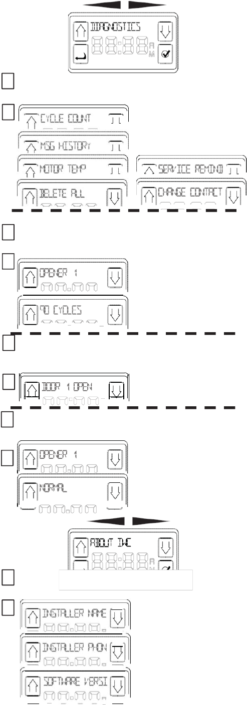
STATUS
RETRIE
V
AL
1
“
C
Y
CLE
COUNT,”“MOTOR
TEM
P
”
and
“
MSG
HIS
T
O
R
Y
”
are
displays of information and have
no
user
functionality.
2
S
ele
c
ting
CYCLE
C
OUNT
presents
the following:
OPENER 1,
2 or
3.
SC
R
OLL
to the
desired
opene
r
.
Pressing
SELECT
will
display
the number
of
cycles
for that
opene
r
.
1
S
ele
c
ting
“MSG
HIS
T
O
R
Y
”
pulls
up the
10 most
r
ece
n
t
operational
e
v
e
n
t
s
.
example only
2
SCROLL
through the list
t
o
view
al
l
.
1
S
ele
c
ting
“MOTOR TEMP” brings
up the
following
displ
a
y
:
OPENER 1,
2 or
3. SCROLL
2 to the
desired
opene
r
.
Pressing
SELECT
will
displ
a
y
the temperature
for that
opene
r
.
1
Pressing
the
SELECT
button will
p
r
ese
n
t
the
following
choi
c
es:
2
Installer Nam
e
,
Installer Phone
or
S
o
f
t
w
a
r
e
Version. These
are
simply displays of the
existing
information. Simply SCROLL
through to retrieve the desired
information. Changing
the
Installer
information
is
done
under the Diagnostics
menu.
c
ontin
ued
15
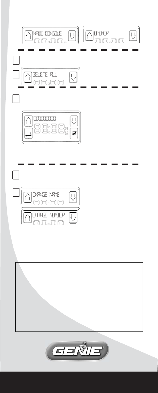
ABOUT
A
WC
c
ontin
ued
RESETTING DEFAULT
VALUES
1
S
ele
c
ting
“
DELETE
ALL
”
2
Removes all openers
from
the
I
W
C
.
SETTING SERVICE
REMINDER
1
S
ele
c
ting
“
SERVICE
REMIND
”
pulls
up the
following
displ
a
y
.
SCROLL
through the
nine
digits to enter the
number
of cycles when you want
to
be reminded to call for a
service
chec
k
.
When
the
opener reaches
that total number of
cycles,
the
display
will remind you to
call service and
g
i
v
e
you the phone number to
cal
l
.
CHANGING
YOUR
C
ON
T
A
CT
1
S
ele
c
ting
“
CHANGE CONTACT
” presents
the
following
displ
a
y
:
To change the name press
2
SELECT and SCROLL
through
each character to spell
it out
or. press SCROLL first,
to
shift to the CHANGE
NUMBER
displ
a
y
.
FCC
& IC CERTIFIED
This device complies with part 15 of the
FCC Rules and RSS 210 Industry Canada standard.
Operation is subject to the
following
two conditions:
(1) This device may not cause
harmful interference, and (2)
this device
must accept any interference received, including
interference that
may cause
undesired
operation. This
equipment
generates, uses and
can radiate radio frequency energy
and,
if
not installed and used in accordance with the
instructions, may cause
harmful
interference to radio communications. However, there
is
no guarantee that interference
will not occur in a
particular situation. If this
equipment
does cause
harmful interference
to radio or television reception, which may
be determined by turning the
equipment
OFF
and ON,
the user is encouraged to try and
correct the interference by one
or more
of the following
measures: (a) Re-orient or relocate the receiver antenna, (b)
increase
the
separation between the opener and receiver,
(c) Connect the opener into an
outlet
on a circuit different from that which the receiver is connected, and (d) Consult
your
local dealer. Any modifications or changes to this equipment which are
not
expressly
approved by Overhead Door® Corp. could void the user’s authority to
operate
the equipment.
.
1
Door
Dr
iv
e
,
Mt
.
Hope
,
Ohio
44660
©2012 The Genie
C
ompan
y

(I
NTELLIGENT C
ONSOLE M
Pour toutes questions et assistance
:
1.800.275.6187
ou visitez
notre site www.overheaddoor.com
CONSERVER CE
MANUEL À
TITRE DE RÉFÉRENCE
ULTÉRIEURE.
INSTALLATEUR : LAISSER
CE
MANUEL AU PROPRIÉTAIRE DES
LIEUX.
Genie, Genie logo, Intellicode
&
Safe-T-Beam
et le
logo Ribbon
sont des marques déposées
de Genie Company.
©
2012 The Genie Company PN# 37381500131,
05/2012

DBA ©2011
C
a
r
a
c
t
é
ri
s
t
i
qu
e
s
•
C
a
p
a
b
l
e
d
e
f
a
i
r
e
f
o
n
c
t
i
o
nn
e
r
3
o
u
v
r
e-
p
o
r
t
e
s
d
e
g
a
r
a
g
e
e
t
3
l
u
m
i
è
r
e
s
d
e
l
'
o
u
v
r
e-
po
r
t
e
•
L
a
d
a
t
e
e
t
l
'
h
e
u
r
e
s
o
n
t
t
o
u
j
o
u
r
s
v
i
s
i
b
l
e
s
à
l
ʼ
é
c
r
a
n
L
C
D
.
L
'
h
e
ur
e
p
e
u
t
s
'
a
ffi
c
h
e
r
e
n
f
o
r
m
a
t
d
e
12
o
u
d
e
24
h
e
ur
e
s
.
L
a
d
a
t
e
p
e
u
t
ê
t
r
e
a
ffic
h
ée
e
n
d
e
u
x
f
o
r
m
a
t
s
JJ
/
MM
/
AAAA
o
u
MM
/
JJ
/
AAAA
.
•
Le
s
m
e
ss
a
g
e
s
d
e
s
t
a
t
u
t
s
s
o
n
t
e
n
r
e
g
i
s
t
r
é
s
d
a
n
s
l
e
fic
h
i
e
r
d
'
h
i
s
t
o
r
i
q
u
e
q
u
i
c
o
n
t
i
e
n
t
l
e
s
10
o
p
é
r
a
t
i
o
n
s
l
e
s
p
l
u
s
r
é
c
e
n
t
e
s
d
e
l
'
o
u
v
r
e-
p
o
r
t
e
.
•
Le
s
y
s
t
è
m
e
S
a
f
e-T
-
B
e
a
m
®
e
s
t
t
o
u
j
o
u
r
s
s
o
u
s
s
u
r
v
e
ill
a
n
c
e
.
S
i
l
e
f
a
i
s
c
e
a
u
e
s
t
b
l
o
q
u
é
,
l
a
c
o
n
s
o
l
e
A
v
a
n
c
ée
C
o
n
s
o
l
e
Mural (IWC)
a
ffi
c
h
e
l
e
m
e
ss
ag
e
B
E
A
M
B
L
O
CK
E
D
.
•
I
n
c
l
u
t
l
e
s
y
s
t
è
m
e
S
u
r
eL
o
c
k
™
q
u
i
,
s
i
a
c
t
i
v
é
,
e
m
p
ê
c
h
e
t
o
u
t
e
o
p
é
r
a
t
i
o
n
à
d
i
s
t
a
n
c
e
(
S
u
r
eL
o
c
k
™
p
e
u
t
ê
t
r
e
u
t
ili
s
é
manuellement
o
u
pa
r
m
i
n
u
t
e
r
i
e
)
.
•
P
e
u
t
ê
t
r
e
u
t
ili
s
ée
p
o
u
r
a
c
t
i
v
e
r
o
u
d
é
s
a
c
t
i
v
e
r
l
e
c
a
p
t
e
u
r
d
e
m
o
u
v
e
m
e
n
t
s
u
r
l
a
t
ê
t
e
m
o
t
o
r
i
s
ée
d
e
l
'
o
u
v
r
e-
p
o
r
t
e
(
s
i
i
n
s
t
a
ll
ée
)
.
Le
c
a
p
t
e
u
r
d
e
m
o
u
v
e
m
e
n
t
d
é
t
e
c
t
e
r
a
l
e
m
o
u
v
e
m
e
n
t
à
l
'
i
n
t
é
r
i
e
u
r
d
u
g
a
r
a
g
e
e
t
a
ll
um
e
r
a
l
a
l
u
m
i
è
r
e
d
e
t
r
a
v
a
il
d
e
l
'
o
u
v
r
e-
po
r
t
e
.
•
Le
n
o
m
e
t
l
e
n
um
é
r
o
d
e
t
é
l
é
ph
o
n
e
d
e
v
o
t
r
e
i
n
s
t
a
ll
a
t
e
u
r
o
u
d
e
l
a
s
o
c
i
é
t
é
a
ss
u
r
a
n
t
l
e
s
e
r
v
i
c
e
l
o
c
a
l
e
m
e
n
t
p
e
u
v
e
n
t
ê
t
r
e
e
n
r
e
g
i
s
t
r
é
s
d
a
n
s
l
'
I
W
C
.
S
i
u
n
e
p
a
nn
e
c
r
i
t
i
q
u
e
s
ur
v
i
e
n
t
p
e
n
da
n
t
l
e
f
o
n
c
t
i
o
nn
e
m
e
n
t
,
u
n
m
e
ss
ag
e
«
a
pp
e
l
e
r
l
e
s
e
r
v
i
c
e
»
s
'
a
ffic
h
e
a
v
e
c
l
e
n
o
m
e
t
l
e
n
um
é
r
o
q
u
e
v
o
u
s
a
v
e
z
s
a
i
s
i
s
.
•
Le
t
e
xt
e
p
e
u
t
ê
t
r
e
a
ffic
h
é
e
n
a
ng
l
a
i
s
,
e
n
e
s
p
a
gn
o
l
o
u
e
n
f
r
a
n
ç
a
i
s
.
L
a
d
u
r
ée
d
'
a
c
t
i
v
a
t
i
o
n
d
u
r
é
t
r
o
é
c
l
a
i
r
a
g
e
d
e
l
'
a
ffic
h
a
g
e
L
C
D
p
e
u
t
ê
t
r
e
d
é
fi
n
i
e
p
a
r
l
'
u
t
ili
s
a
t
e
u
r
q
u
i
p
e
u
t
c
h
o
i
s
i
r
e
n
t
r
e
a
c
t
i
v
a
t
i
o
n
c
o
n
t
i
n
u
e
,
désactivation
o
u
a
c
t
i
v
a
t
i
o
n
s
p
é
c
i
fi
q
u
e
à
u
n
m
o
m
e
n
t
d
o
nn
é
p
e
nd
a
n
t
l
'
u
t
ili
s
a
t
i
o
n
.
•
L
a
d
u
r
ée
d
'
a
c
t
i
v
a
t
i
o
n
d
e
l
a
l
um
i
è
r
e
d
e
l
'
o
u
v
r
e-
p
o
r
t
e
p
e
u
t
ê
t
r
e
d
é
fi
n
i
e
p
a
r
l
'
u
t
ili
s
a
t
e
u
r
p
o
u
r
q
u
e
l
a
l
um
i
è
r
e
r
e
s
t
e
a
ll
um
ée
p
e
nd
a
n
t
u
n
c
e
r
t
a
i
n
t
e
m
p
s
a
p
r
è
s
a
v
o
i
r
u
t
ili
s
é
l
e
bouton
d
e
l
a
l
u
m
i
è
r
e
.
•
Le
s
r
é
g
l
a
g
e
s
d
e
f
o
r
c
e
e
t
d
e
v
i
t
e
ss
e
d
e
l
'
o
u
v
r
e-
p
o
r
t
e
p
e
u
v
e
n
t
ê
t
r
e
a
ffic
h
é
s
p
o
u
r
c
o
n
fi
r
m
e
r
l
e
s
v
a
l
e
u
r
s
p
e
nd
a
n
t
u
n
d
é
p
a
nn
a
g
e
o
u
p
o
u
r
d
é
t
e
r
m
i
n
e
r
s
i
v
o
u
s
d
e
v
e
z
l
e
s
c
h
a
n
g
e
r
.
•
U
n
m
e
ss
a
g
e
Ser
v
i
c
e
r
e
c
o
mm
a
nd
é
s
'
a
ffic
h
e
a
p
r
è
s
u
n
n
o
m
b
r
e
p
r
é
d
é
fi
n
i
d
e
c
y
c
l
e
s
.
Le
n
o
m
b
r
e
d
e
c
y
c
l
e
s
r
e
c
o
mm
a
nd
é
s
p
e
u
t
ê
t
r
e
r
é
g
l
é
p
a
r
l
'
i
n
s
t
a
ll
a
t
e
u
r
.
2
Les
ouvre-portes que vous voulez utiliser doivent
etre
dotes d'un adaptateur de reseau pour pouvoir recevoir les
signaux emis par
Ia
Intelligent
Console
Murale.
Pour pouvoir utiliser !'Intelligent Console Murale ainsi
que
I'Adaptateur de
reseau-ce
type
d'etiquette
doit
etre
appose
sur votre
ouvre-porte-
ATTENTI
Q
N:
un auto-collant du
type
d
e
celui-ci indiquant un
numer
o
d
e
serie
dont
le
s
deux
premiers
chiffre
s
son
t
10
ou plu
s
doit
figurer
sur
votre
ouvre-
porte
d
e
garage.
THE GENIE
COMPANY
Residential Door
Operator
1
20V.
60HZ.
SA
7 187WWW.GENIE MPANY.
M
et doivent disposer d'un port de connexion
pour
Adaptateur de reseau (illustration
ci-dessous).
Si
votre
ouvre-porte
ne satisfait pas
a
ces
criteres,vous ne
pourrez
pas utiliser
Ia
Intelligent
Console
Murale.
Si
vous ne disposez pas d'Adaptateur de reseau ou
si
vous
avez besoin d'adaptateurs
supplementaires-contactez
votre revendeur OverheadDoor®.
REMARQUE:
si
au cours de Ia programmation,le message
PAS DE RESEAU
s'affiche,effectuez les
verifications
suivantes:
•
Les
fil
s
d'alimentation
sont
correctement
connectes
sur les bornes 5 et 6 de
Ia
tete
motorisee?
•
Est-ce
que l'adaptateur est bien
introduit?
Le
voyant
vert
estallume?
•
Avez-vous
relie
I'IWC
a
l'adaptateur?
(voir page 8)
A
AVERTISSEMENT
Toute porte en
mouvement
peut
entrainer
de graves blessures voire Ia
mort.
·La console murale doit etre
instaiiE§e
en vue
de
Ia
porte,
a au
moins
1,5 m au-dessus du sol
eta
l'ecart
des pieces
mobiles
de
Ia
porte.
• Ne
laisser personne
dans l'encadrement de
Ia
porte
pendant qu'elle est
en
mouvement.
•
Ne pas
permettre aux enfants
de
jouer avec les
telecommandes
ou l'ouvre-porte.
Si le
systeme d'inversion
ne
fonctionne
pas
correctement,
procedez com me suit
:
• Fermer
d'abord
Ia
porte puis deconnecter
I'
ouvre-porte
a
I'
aide
de
Ia
poignee de declenchement
manuel.
• Ne
pas
utiliser Ia
telecommande ni
l'ouvre-porte.
• Se reporter aux manuels
de
Ia porte et
de
l'operateur
de
Ia
porte
avant de tenter
toute reparation.
3
console murale de base.
INSTALLATION
(si
necessaire
)
L'ADAPTATEUR
DE
RESEAU
!
L'INTELLIGENT
CONSOLE
MURALE
Cette console est alimentee par Ia tete motorisee
de
l'ouvre-porte (alimentee
uniquement
par un
ouvre-porte).
•
Les
fils
d'alimentation
sont
correctement connectes
sur les
bornes
5 et 6 de Ia tete
motorisee?
rTl Avec
until
a
cloche standard
a
deux
conducteurs-
ez
l'extremite
a
Ia tete motorisee souhaitee au
niveau
des bornes 5 et 6 (voir
illustration
)
.
BORNES SITUEES DANS LA
LENTILLE
DE LA LUMIERE
CD®@@ @@
STB
BWC
IWC
REMARQUE:vous pouvez utiliser I'IWC
a
Ia place
d'une
2
2
Acheminez
le fil
depuis la
tête
motorisée
de
l'ouvre-porte choisi (un
seul
ouvre-porte
est
requis
pour le
câblage vers la console
d'un groupe de 3
ouvre-portes*)
vers
l'emplacement
de
l'installation
de
la console en vous
assur
an
t
que l'acheminement
est
effectué à l'écart de pièces ou d'équipement
mobiles
.
Assurez-vous
que l'installation est
sécur
isée
.
Si
vous
utilisez des agrafes isolées, prenez soin
de
ne
pas
pincer ni couper le
fil
.
Agrafez de manière à ce que
le
fil
tienne en place sans exercer
de
f
or
ce
.
3
I
nstallez
la console à l'aide des vis
f
our
nies
.
A
Déverrouillez
et
enlevez le
s
u
pp
o
r
t
de
fi
x
a
t
i
o
n
.
S
U
PP
O
R
T
DE
F
IX
A
T
I
O
N
L
OQU
E
T
B
Enlevez les vis situées
à
l'arrière de la
C
o
n
s
o
l
e
.
*
Pour utiliser les
ouvre-portes de
garage 2 ou 3,
vous
n'avez besoin que d'un IWC câblé à l'ouvre-porte de
v
otre
choix pour l'alimentation.
(Toutefois, chaque
ouvr
e
-p
or
t
e

console murale de base.
DOIT
disposer
de
son
pr
opr
e
adaptateur
de
r
éseau).
2
C
Fixez le
s
u
pp
o
r
t
de
fixation
au
mur du
g
a
r
a
g
e
.
D
Fixez les fils aux bornes
à
l'arrière de la console
:
E
Fixez la console au
s
u
pp
o
r
t
de
fixation
en
la
g
li
ss
a
n
t
vers le bas par dessus le
bord
supérieur
de
support et en la pivotant contre le support jusqu'à
c
e
que
le
loquet
s
'
e
n
g
a
g
e
.
1 2 3
I
W
C
M
U
R
S
U
PP
O
R
T