The Sapling MOD-24G-1 2.4 GHz FHSS Transceiver User Manual
The Sapling Company, Inc 2.4 GHz FHSS Transceiver
UserManual.wiki
>
The Sapling
>
MOD-24G-1 User Manual
>
USER MANUAL
Contents
1.
OEM MANUAL
2.
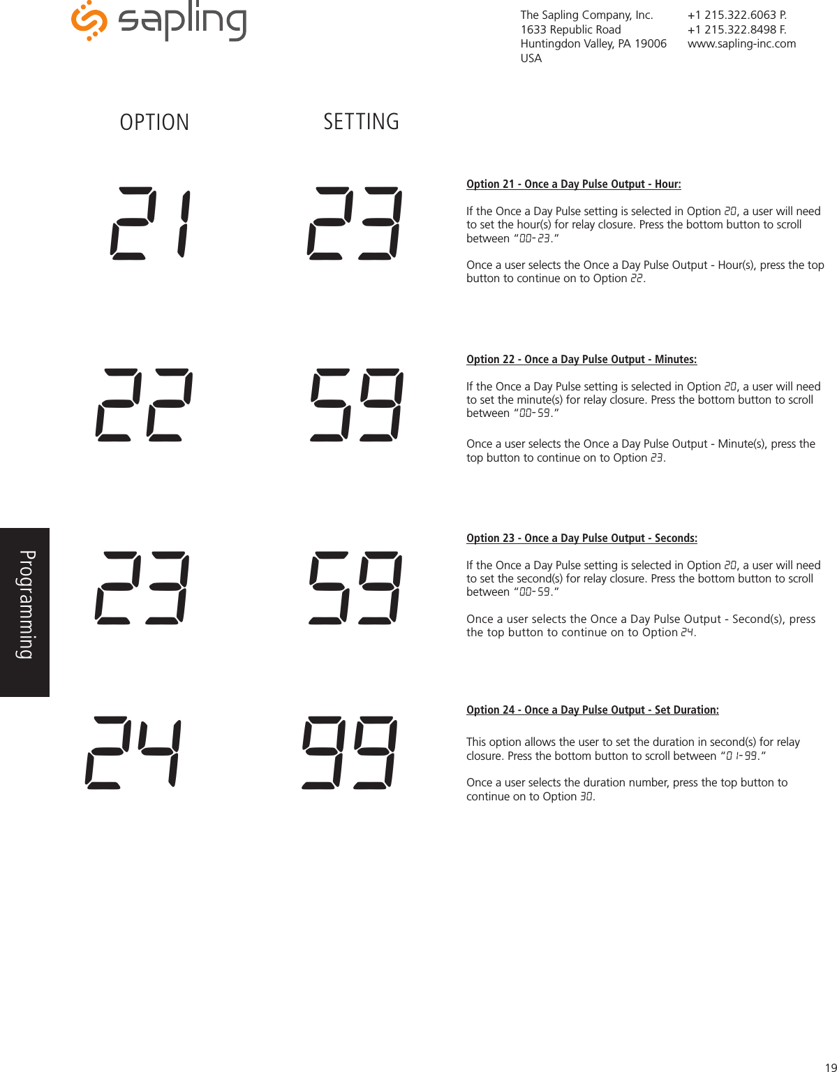
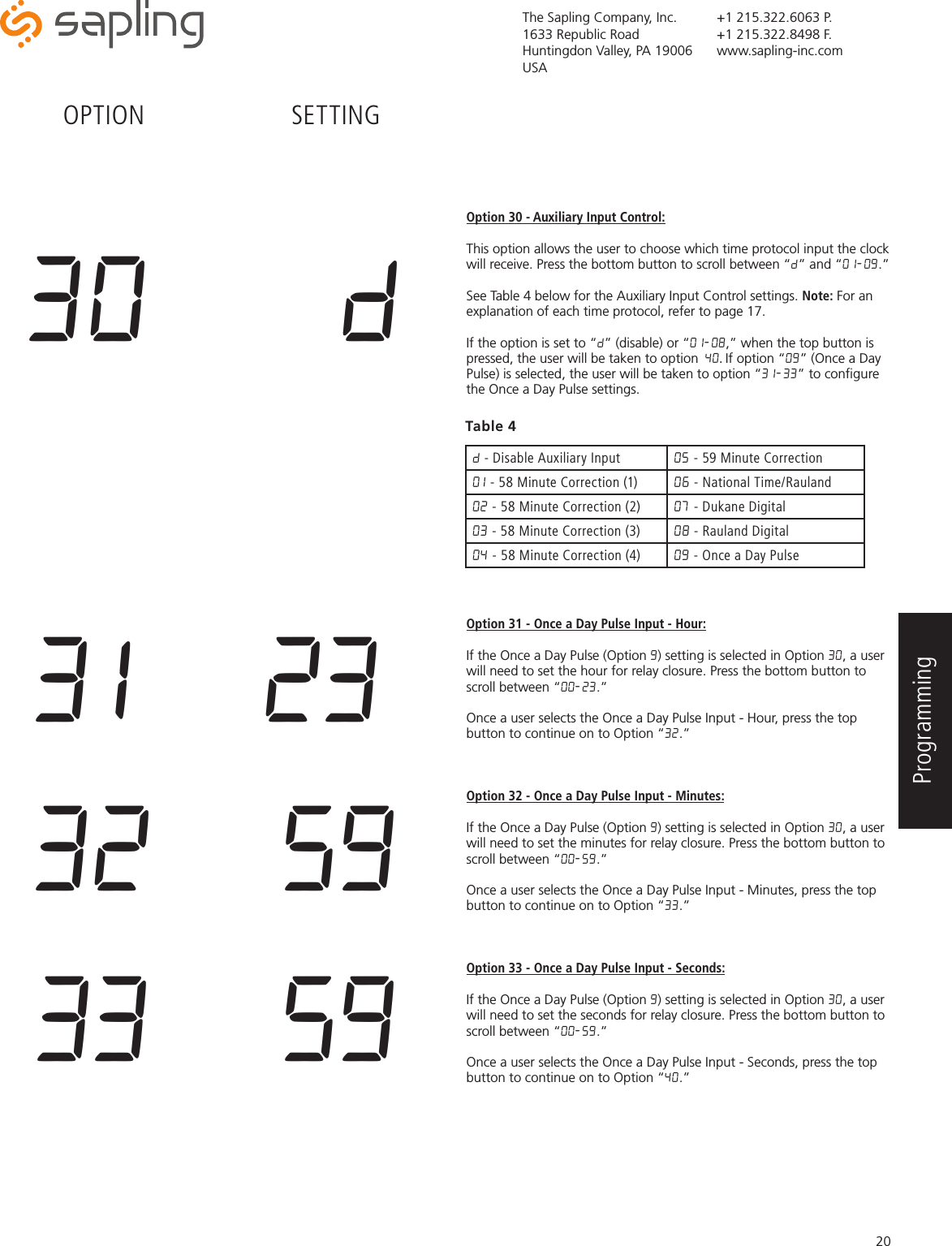
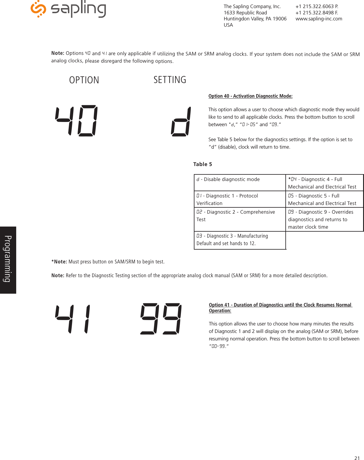
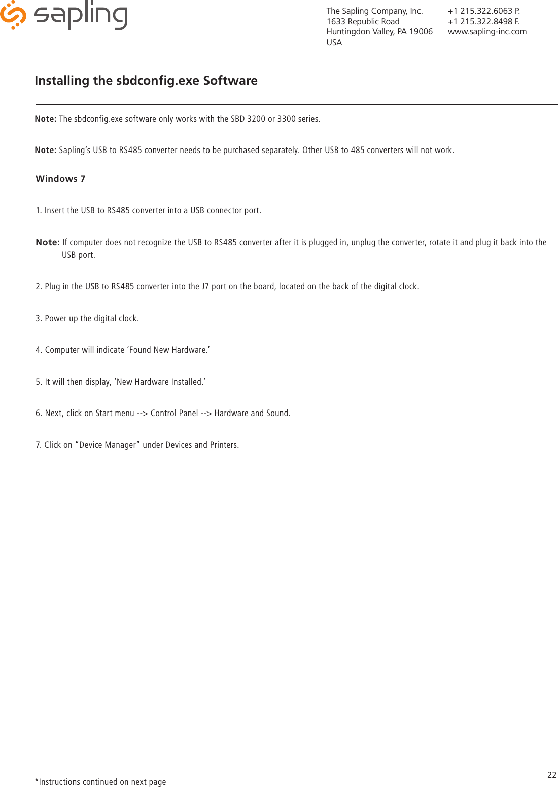
USER MANUAL
USER MANUAL
Navigation menu
Upload a User Manual
Namespaces
Wiki Guide
HTML
PDF
Info
Views
User Manual
Discussion / Help
Navigation