The Sapling MOD-24G-1 2.4 GHz FHSS Transceiver User Manual
The Sapling Company, Inc 2.4 GHz FHSS Transceiver
Contents
- 1. OEM MANUAL
- 2. USER MANUAL
USER MANUAL
SBL 3000 Series Wireless Clock
The Sapling Company, Inc.
1633 Republic Road
Huntingdon Valley, PA 19006
USA
+1 215.322.6063 P.
+1 215.322.8498 F.
www.sapling-inc.com
Installation and Programming Manual V4
Software Version:
SW-USB485V1.1.0_8-22-13

The Sapling Company, Inc.
1633 Republic Road
Huntingdon Valley, PA 19006
USA
+1 215.322.6063 P.
+1 215.322.8498 F.
www.sapling-inc.com
2
Table of Contents
SBL 3000 Series Wireless Clock
Table of Contents—2
Installation
Included in the Kit—3
Plastic Surface (Wall) Mount Installation—4
Plastic Surface (Wall) Mount Installation (continued)—5
Plastic Double Mount Installation—6
Plastic Double Mount Installation (continued)—7
Plastic Double Mount Installation (continued)—8
Wiring Information
Wiring and Jumper Settings (3100 Series)—9
Wiring and Jumper Settings (3200 Series)—10
Wiring and Jumper Settings (3300 Series)—11
Using the Output Sync Relay on the SBL 3300—12
Temperature Sensor—13
Programming
Setting the Time on the SBL 3300 - Programming the SBL 3300—14
Programming the SBL 3300 (continued)—14-21
Software
Installing the Sbdconfig.exe Software—22-25
Sbdconfig Software - Task Bar Functionality—26-27
Sbdconfig Software - Display Settings—28
Sbdconfig Software - Brightness Schedule—29
Sbdconfig Software - Clock Settings—30
Sbdconfig Software - Outputs—31
Sbdconfig Software - Elapsed Timer—32-34
Sbdconfig Software - Inputs—35-36
Sbdconfig Software - DST—37-38
Support
Frequently Asked Questions—39
Troubleshooting—40
FCC Statements—41
Index—42-43
*Manuals may change without prior notice

The Sapling Company, Inc.
1633 Republic Road
Huntingdon Valley, PA 19006
USA
+1 215.322.6063 P.
+1 215.322.8498 F.
www.sapling-inc.com
3
Included in the Kit
Surface Mount – 24VAC Kit
Kit will be labeled: D-PK-3-24-S
• 24VAC Power Harness (18 AWG), Orange, Green, Yellow
Kit will be labeled: D-MK-WLL-PLTC-1
• 4 - 6-32 x 1” Machine Flat Screws
• 4 - 6-19 x 1/2” Flat Head Screws
• 4 - 8-32 x 7/19” Screws
• 2 - 8-32 x 7/16” Screws
Surface Mount - 120VAC or 240VAC Kit
Kit will be labeled: D-PK-3-110-S
• 120VAC or 240VAC Harness (18 AWG), Black, Green, White
Kit will be labeled: D-MK-WLL-PLTC-1
• 4 - 6-32 x 1” Machine Flat Screws
• 4 - 6-19 x 1/2” Flat Head Screws
• 4 - 8-32 x 7/19” Screws
• 2 - 8-32 x 7/16” Screws
Below is a list of all the items included in the SBL 3000 installation kit. The items in the kit will correspond to the type of mounting and voltage
option chosen.
Installation
The Sapling Company, Inc.
1633 Republic Road
Huntingdon Valley, PA 19006
USA
+1 215.322.6063 P.
+1 215.322.8498 F.
www.sapling-inc.com
4
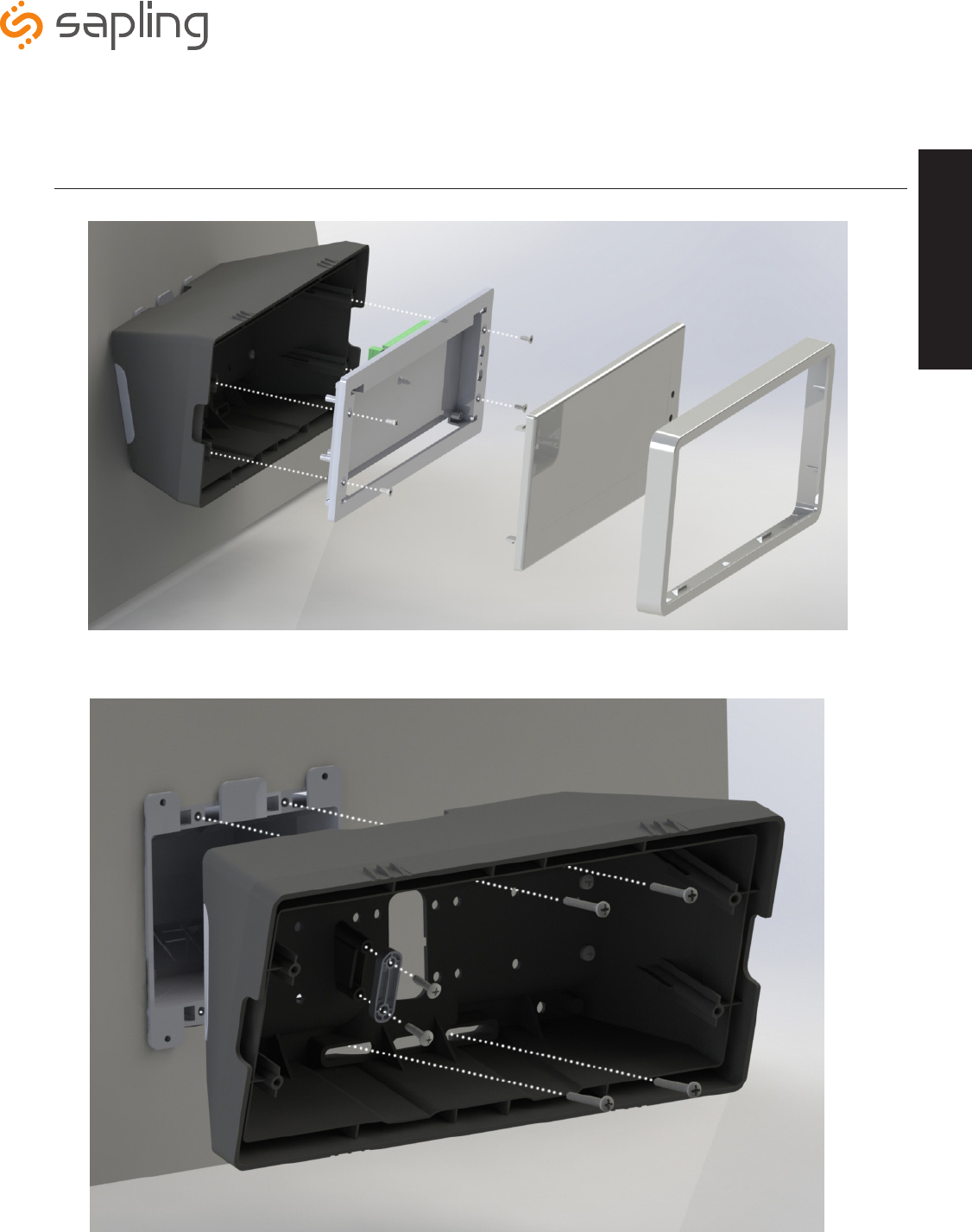
Plastic Surface (Wall) Mount Installation
Installation
q
e
rty
w

The Sapling Company, Inc.
1633 Republic Road
Huntingdon Valley, PA 19006
USA
+1 215.322.6063 P.
+1 215.322.8498 F.
www.sapling-inc.com
5
1. Mount Housing to Wall and/or Gang Box - To mount the housing to the wall, install two (2) wall anchors into the wall (not supplied
in kit) and take two pan head screws no larger than #8 (also not supplied in kit) and drive them into the anchors leaving an 1/8th inch
gap between the head of the screw and the wall. Mount the housing to the wall by lining up the two keyholes in the back of the housing
with the two screws with the 1/8 inch gap and slide the housing onto the heads of the screws. Next, mark the 2 mounting holes at the
bottom of the housing on the wall. Remove the housing and install wall anchors at this location. Hang the housing on the keyholes and
install the bottom screws. To mount the housing to the gang box, take the four (4) 6-32 x 1” screws (supplied in kit) and screw them
through the four holes in the center of the inside of the housing and the four holes in the gang box.
Note: If using a metal gang box, a ground must be provided to the gang box.
2. Feed Wiring Into the Housing - Take the wire coming from the inside of the gang box and feed it through the hole in the middle of
the housing.
3. Plug and Secure Wiring - Loosen the provided wire clamp (comes attached to the inside of the housing) and slip excess wiring
through and tighten the clamp. After securing excess wiring, connect the wiring into the appropriate connector on the back of the
display board. (See the Wiring and Jumper Settings on page 9-11).
4. Mount Display Board to Housing - Using the four (4) self tapping, 6-19 x 1/2” flat head screws (supplied in the assembly kit), take
the display board and screw it to the front side of the clock housing (4 screws per clock).
5. Snap on Filter - Take the red filter bezel and snap it on to the front side of the housing.
6. Snap on Frame - Take the gray frame and snap it on to the front side of the housing.
Plastic Surface (Wall) Mount Installation (continued)
Installation
The Sapling Company, Inc.
1633 Republic Road
Huntingdon Valley, PA 19006
USA
+1 215.322.6063 P.
+1 215.322.8498 F.
www.sapling-inc.com
6
Plastic Double Mount Installation
Installation
q
w
e
e
r
t
u
o
a
y
i

The Sapling Company, Inc.
1633 Republic Road
Huntingdon Valley, PA 19006
USA
+1 215.322.6063 P.
+1 215.322.8498 F.
www.sapling-inc.com
7
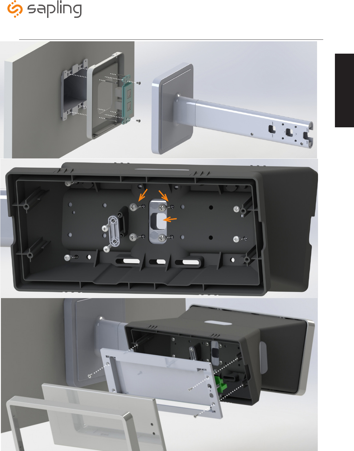
Plastic Double Mount Installation (continued)
*For metal mounting bracket: Use a wall anchor that can support 50 lbs or more with a maximum
screw size of #8
1. Install metal mounting bracket - First, remove the metal mounting bracket from the inside of the double mount base by unscrewing
the two (2) 6-32 x 1/2” screws located on the underside of the base (save these screws for step #5). Next, screw the metal mounting
bracket to the wall or ceiling in which the clocks are being installed. To mount to the double gang switch box, screw the four (4) 6-32 x
1” screws (supplied in the assembly kit) through the inner four holes of the metal mounting bracket. Use the outer four holes to mount to
the anchors in the wall (both anchors and screws are not supplied in kit).
Note: If using a plastic switch box, a ground wire must be routed through the switch box and into one (1) of
the four (4) metal mounting bracket screws in order to provide ground to the metal mounting bracket. The metal
mounting bracket
MUST
be secured by both the screws going to the switch box
AND
the anchors going into the
wall.
2. Mount clock housings to pole - Align the hole in the center each housing with one of the three holes on the mounting pole where
the wiring will be routed (the installer will choose which hole at the end of the pole to use based on how far they want the clock to sit
from the wall). Screw from the inside of the housing into the four holes surrounding the hole in the center of the housing using the four
(4) 8-32 x 7/16” screws (supplied in the assembly kit - 4 screws per clock), securing both housings to the mounting pole.
Note: End caps from one side of each clock must be removed to mount both clocks to the mounting pole.
Remove one end cap from each clock from the side in which the mounting pole enters the clock.
*Instructions continued on next page
3. Screw both housings together - Using the two (2) self tapping, 6-19 x 7/16” screws (supplied in the assembly kit), screw both back
sides of the clock housings together (2 screws per clock).
Installation

The Sapling Company, Inc.
1633 Republic Road
Huntingdon Valley, PA 19006
USA
+1 215.322.6063 P.
+1 215.322.8498 F.
www.sapling-inc.com
8
Plastic Double Mount Installation (continued)
4. Feed wiring through base and pole - Take the wiring coming from the switch box and begin to feed it through the center of the
base of the mounting assembly until it emerges from the hole in the center of the clock housing. Make sure there is roughly 1.5’ of
wiring coming from the switch box. Perform this task for both clocks.
5. Snap and screw base to metal mounting bracket - Snap the base to the metal mounting bracket by first making contact with
the lip in the upper side of the base and the metal mounting bracket. When the base has been snapped onto the bracket, take
the two (2) 6-32 x 1/2” pan head screws that originally came installed on the base and screw them back into the two holes on the
underside of the base to secure the base to the metal mounting bracket.
6. Connect switch box wires to clock harness - Take the wiring harness supplied with the clock and make all necessary
connections between the wiring harness and the switch box wires using wire nuts. Perform this task for both clocks.
7. Plug and secure wiring - Loosen and slip excess wiring through provided wire clamp (comes attached to each housing) and
tighten the clamp. After securing excess wiring, connect the wiring harness into the appropriate connector on the back of the
display board. Perform this task for both clocks. (See the Wiring and Jumper Settings on page 9-11).
8. Mount display board to housing - Using the four (4) self tapping, 6-19 x 1/2" flat head screws supplied in the assembly kit,
take the display board and screw it to the front side of the clock housing (4 screws per clock).
9. Snap on filter - Take the red filter bezel and snap it on to the front side of each clock housing.
10. Snap on frame - Take the gray frame and snap it on to the front side of each clock housing.
Installation
The Sapling Company, Inc.
1633 Republic Road
Huntingdon Valley, PA 19006
USA
+1 215.322.6063 P.
+1 215.322.8498 F.
www.sapling-inc.com
9
Wiring Information
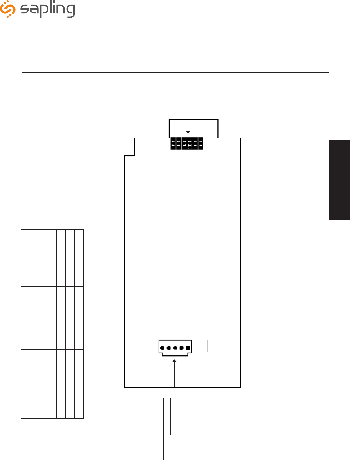
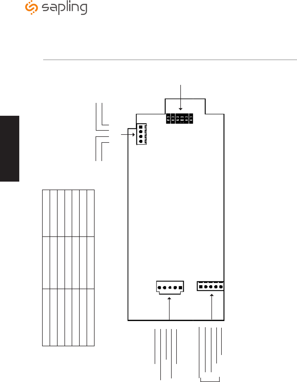
Wiring and Jumper Settings (3100 Series)
**Jumper Position
JP 1
JP 4
JP 5
JP 6
JP 2
JP 3
Power Settings
1
4
5
2
3
24VAC @ 0.35A (ORG)
120VAC or 240VAC @ 0.1A (BLK)
No Connection
120VAC or 240VAC @ 0.1A (WHT)
24VAC @ 0.35A (YEL)
Note: When setting up the jumpers, Pin 1 & Pin 2 must be jumpered together OR
Pin 2 & Pin 3 must be jumpered together. Below are the Jumper Positions and what
function each corresponds with.
Pin
1 2 3
Jumper Position Pin 1 & Pin 2 Pin 2 & Pin 3
JP 1 12 Hour Time 24 Hour Time
JP 2 Bright Dim
JP 3 Time Display Only Alternating Date/Time Display
JP 4 Normal Configuration
JP 5 Real Time Clock 60Hz
JP 6 Sync RS485 Select
Wiring Information
Note: Pin 1 will always be
the square pad.
The Sapling Company, Inc.
1633 Republic Road
Huntingdon Valley, PA 19006
USA
+1 215.322.6063 P.
+1 215.322.8498 F.
www.sapling-inc.com
10
Wiring Information
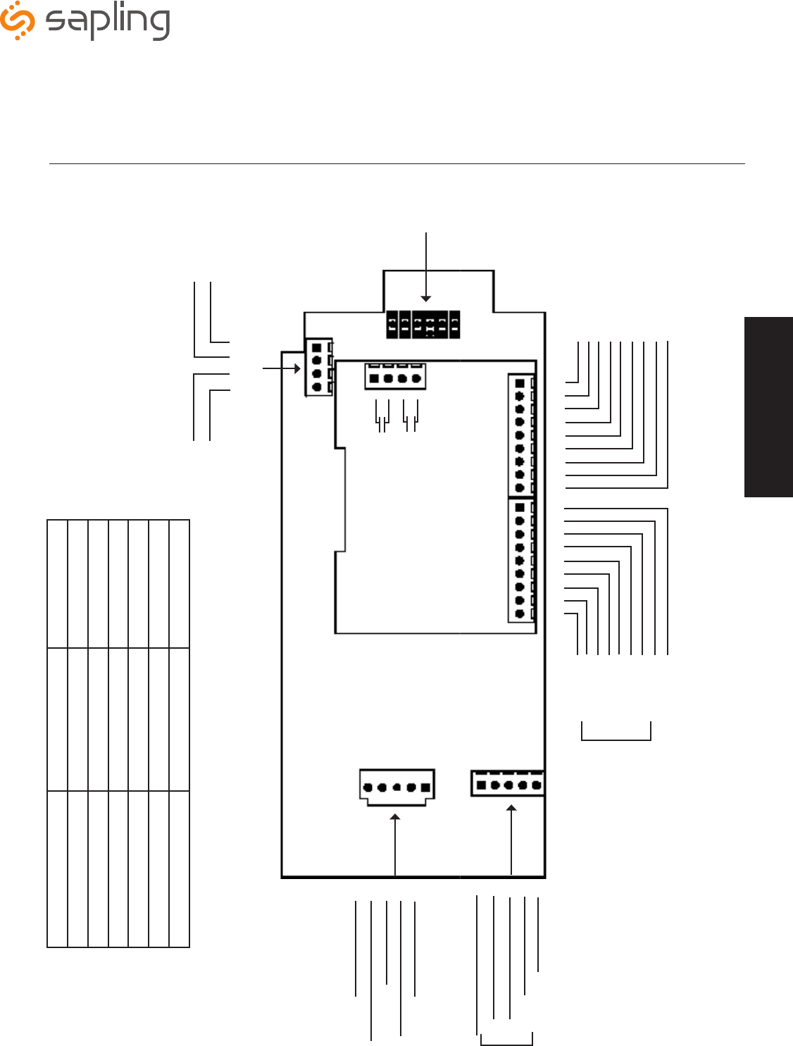
Wiring and Jumper Settings (3200 Series)
**Jumper Position
JP 1
JP 4
JP 5
JP 6
JP 2
JP 3
Power Settings
1
4
5
2
3
24VAC @ 0.35A (ORG)
120VAC or 240VAC @ 0.1A (BLK)
No Connection
120VAC or 240VAC @ 0.1A (WHT)
24VAC @ 0.35A (YEL)
Elapsed Timer
5
2
1
4
3
No Connection
TXD (Blue&Blue/White)
Common (Green&Green/White)
RXD (Orange&Orange/White)
3.3V@0.1A (Brown&Brown/White)
P1 - Sync Inputs P2 - User Inputs
P3 - Relay Output
4
3
2
1
*Relay 1 N.O.
*Relay 2 N.O.
Note: When setting up the jumpers, Pin 1 & Pin 2 must be jumpered together OR
Pin 2 & Pin 3 must be jumpered together. Below are the Jumper Positions and what
function each corresponds with.
Pin
1 2 3
Jumper Position Pin 1 & Pin 2 Pin 2 & Pin 3
JP 1 12 Hour Time 24 Hour Time
JP 2 Bright Dim
JP 3 Time Display Only Alternating Date/Time Display
JP 4 Normal Configuration
JP 5 Real Time Clock 60Hz
JP 6 Sync RS485 Select
Cat 5
Cable
Wiring Information
P7 - RS485
1 2 3 4
Input A
Input B
Output A
Output B
Note: Pin 1 will always be
the square pad.
The Sapling Company, Inc.
1633 Republic Road
Huntingdon Valley, PA 19006
USA
+1 215.322.6063 P.
+1 215.322.8498 F.
www.sapling-inc.com
11
Wiring Information
Wiring and Jumper Settings (3300 Series)
**Jumper Position
JP 1
JP 4
JP 5
JP 6
JP 2
JP 3
Power Settings
1
4
5
2
3
24VAC @ 0.35A (ORG)
120VAC or 240VAC @ 0.1A (BLK)
No Connection
120VAC or 240VAC @ 0.1A (WHT)
24VAC @ 0.35A (YEL)
Elapsed Timer
5
2
1
4
3
No Connection
TXD (Blue&Blue/White)
Common (Green&Green/White)
RXD (Orange&Orange/White)
3.3V@0.1A (Brown&Brown/White)
P1 - Sync Inputs P2 - User Inputs
12 3 4 5 6 7 8 9 12 3 4 5 6 7 8 9
AC / DC Com
120VAC or 240VAC Sync
24VAC Sync
Dukane Reset
Dukane Pulse
Dry Contact
3.3VDC@20ma
Common
Common
User Input 4
User Input 3
User Input 2
User Input 1
12VDC@40ma
Each User Input is
a Contact Closure
P3 - Relay Output
4
3
2
1
*Relay 1 N.O.
*Relay 2 N.O.
*Contact Rating
0.3A @ 120VAC
0.5A @ 24 VAC
Note: When setting up the jumpers, Pin 1 & Pin 2 must be jumpered together OR
Pin 2 & Pin 3 must be jumpered together. Below are the Jumper Positions and what
function each corresponds with.
Pin
1 2 3
Jumper Position Pin 1 & Pin 2 Pin 2 & Pin 3
JP 1 12 Hour Time 24 Hour Time
JP 2 Bright Dim
JP 3 Time Display Only Alternating Date/Time Display
JP 4 Normal Configuration
JP 5 Real Time Clock 60Hz
JP 6 Sync RS485 Select
Cat 5
Cable
Wiring Information
P7 - RS485
1 2 3 4
Input A
Input B
Output A
Output B
Note: Pin 1 will always be
the square pad.
The Sapling Company, Inc.
1633 Republic Road
Huntingdon Valley, PA 19006
USA
+1 215.322.6063 P.
+1 215.322.8498 F.
www.sapling-inc.com
12
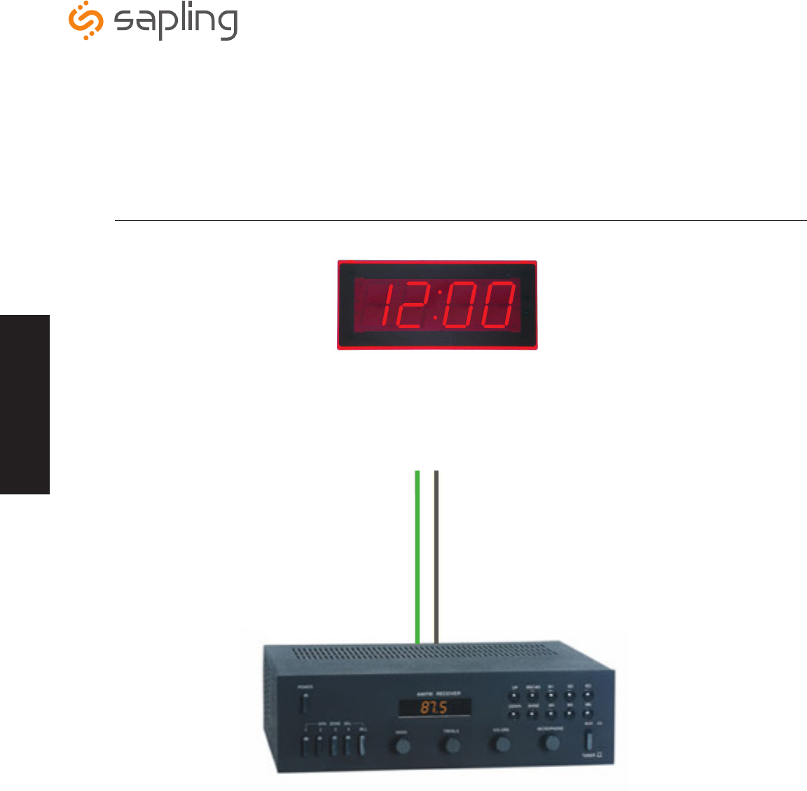
Using the Output Sync Relay (SBL 3300 Series Only)
Intercom, paging system, or other device
Wiring Information
Output Relay
Green
White
(Relay 1) P3 - 1 & 2
or
(Relay 2) P3 - 3 & 4
Relay Input
Wiring Information
The Sapling Company, Inc.
1633 Republic Road
Huntingdon Valley, PA 19006
USA
+1 215.322.6063 P.
+1 215.322.8498 F.
www.sapling-inc.com
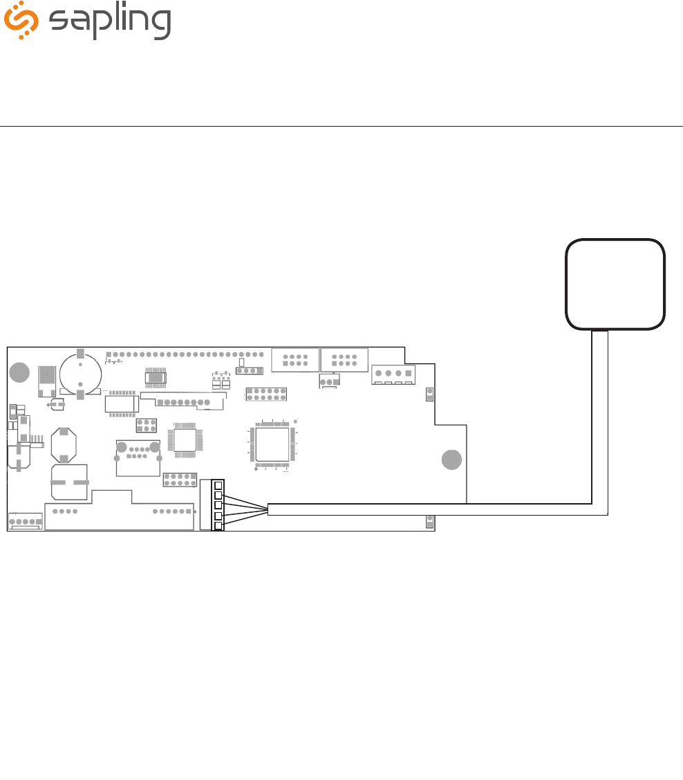
Temperature Sensor Wiring (Optional)
If you ordered a Temperature Sensor with your SBD 3000 clock, it
must be connected to a terminal on the Clock.
Connecting The Temperature Sensor
Temperature Sensor
Sensor Cable
(IMPORTANT: Detach clock from power source before installing
new circuitry. DO NOT add new circuitry while the clock is operating)
Attach the end of the Temperature Sensor Wire to the circuit board in
the following manner:
Data from the temperature sensor will be sent to your clock when
the clock is powered on. For more information on how to make the
SBD 3000 display temperature, please see the section labeled “Web
Interface - Display Settings”.
The Sensor Cable is 6 feet (1.83 meters) long, and so the sensor
should be positioned within 6 feet of the clock. The cable is
unshielded, 4 conductor, 22AWG (.33mm²). If longer than 6 feet is
required, the wire would have to be terminated in an electrical box,
and the longer wire would have to be provided by the customer.
1
2
3
4
5
5) No connection
4) White
3) Black
2) Green
1) Red
13
The Sapling Company, Inc.
1633 Republic Road
Huntingdon Valley, PA 19006
USA
+1 215.322.6063 P.
+1 215.322.8498 F.
www.sapling-inc.com
14
Programming
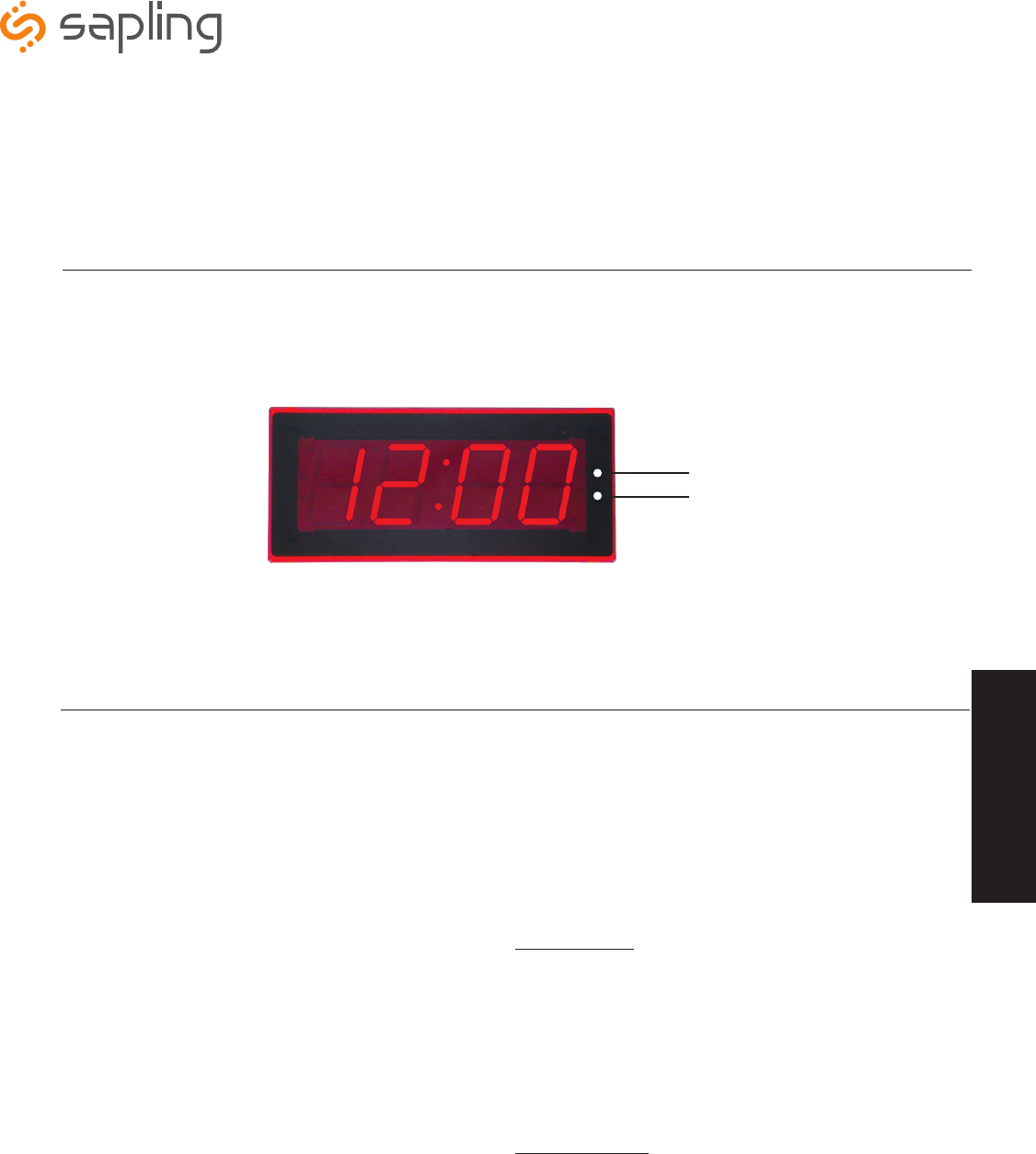
Setting the Time (SBL 3300 Series Only)
1. To set the time, press the top button to set the hour and the bottom button to set the minute.
Programming the SBL 3300
1. To enter programming mode, simultaneously press the top and bottom buttons.
2. Press the top button to select an Option. Hold the button down to scroll through the Options.
3. Press the bottom button to select a Setting. Hold the button down to scroll through the Settings.
4. To return to time while in an Option, simultaneously press the top and bottom buttons.
Option 1 - Set Year:
This option will allow the user to set the current year.
Press the bottom button to scroll between “01-99” on the display in
order to set the year.
Once the year is selected, press the top button to continue on to
Option 2.
Option 2 - Set Month:
This option will allow the user to set the current month.
Press the bottom button to scroll between “01-12” on the display to set
the month.
Once the month is selected, press the top button to continue on to
Option 3.
Set Hour
Set Minute
1 12
OPTION SETTING
2 12
Programming

The Sapling Company, Inc.
1633 Republic Road
Huntingdon Valley, PA 19006
USA
+1 215.322.6063 P.
+1 215.322.8498 F.
www.sapling-inc.com
15
Option 3 - Set Day:
This option will allow the user to set the current date.
Press the bottom button to scroll between “01-31” on the display to
set the date.
Once the date is selected, press the top button to continue on to
Option 4.
Option 4 - Set 12/24 Hour Format:
This option will allow the user to select the mode the time is displayed
in. There are two options: 12 hour format or 24 hour format.
Press the bottom button to scroll between "12 or 24.”
Once 12 hour format or 24 hour format is selected, press the top
button to continue on to Option 5.
Option 5 - Daylight Saving Time:
This option will allow the user to select the Daylight Saving Time setting.
Press the bottom button to scroll between “E or d.”
Option “E” will enable the current USA Daylight Saving Time
schedule seen below:
• DST starts 2nd Sunday of March at 2:00 am
• DST ends 1st Sunday of November at 2:00 am
Option “d” will disable the Daylight Saving Time setting. Note: If a
different Daylight Saving Time setting is needed, it must be configured
via the web interface. See page 36 for more information.
Once the Daylight Saving Time option is selected, press the top button
to continue on to Option 6.
Option 6 - Alternating Date/Time:
This option will allow the user to enable or disable the Alternating Time/
Date display. Press the bottom button to scroll between “E or d.”
When enabled (E), the display will switch between showing the time
(HH:MM:SS) and the date (MM:DD:YY) for 6 digit, (HH:MM) and
(MM:DD) for 4 digit. When disabled (d), the display will show only the
time.
Once the Alternating Date/Time option is selected, press the top button
to continue on to Option 7.
4 24
5 d
6 d
OPTION SETTING
3 21
Programming

The Sapling Company, Inc.
1633 Republic Road
Huntingdon Valley, PA 19006
USA
+1 215.322.6063 P.
+1 215.322.8498 F.
www.sapling-inc.com
16
Option 7 - American or European Date Style:
This option will allow the user to choose what style the date is displayed
on the digital clock. Press the bottom button to scroll between “A” or
“E.”
“A” stands for American style and displays the date as follows: month,
day and year (ex. 10 28 12). “E” stands for European style and displays
the date as follows: day, month and year (ex. 28 10 12).
The date will be displayed during normal operation only if the
“Alternate Time/Date” option has been enabled in Option 6.
Once the date style is selected, press the top button to continue on to
Option 8.
Option 8 - Brightness:
This option allows the user to choose the brightness level the digital
clock will display. Press the bottom button to scroll between “00,” “01”
and “02.”
• Level “02” is High (default)
• Level “01” is Medium
• Level “00” is Low
Note: The user has the ability to create a Brightness Schedule for the
clocks. Refer to page 28 for more information.
Once the brightness level is selected, press the top button to continue
on to Option 9.
Option 9 - Set the Clock Number:
This option allows the user to choose a specific clock number in order to
easily identify a specific clock within the system. Use the bottom button
to scroll between “1-999.”
An example of a clock number is “123.”
Once the clock number is selected, press the top button to continue on
to Option 10.
Options 9 also allows a user to address a specific clock for displaying
messages, such as 911, BELL or FiRE using a Sapling Master Clock.
Option 9 sets the clock number. This is step 1 of 2. Step 2 of this
process can be completed in Option 10.
Option 10 - Set the Zone Number:
This option allows the user to choose a zone number for a specific
clock. A zone number is a collection or grouping of clocks within a
certain section of a facility. Press the bottom button to scroll between
"01-99."”
An example of a zone number is “12.”
Once the zone number is selected, press the top button to continue on
to Option 11.
Option 10 programs the zone number in order to display
messages on each clock in a zone, such as 911, BELL or FiRE.
Note: The message feature must be programmed via the master clock.
Refer to the specific master clock manual for more information.
9 1
10 01
8 02
OPTION SETTING
7 A
Programming
The Sapling Company, Inc.
1633 Republic Road
Huntingdon Valley, PA 19006
USA
+1 215.322.6063 P.
+1 215.322.8498 F.
www.sapling-inc.com
17
Option 11 - RS485 Data Rate:
This options allows a user to set the RS485 data rate. The RS485 data
rate is the rate at which data (for example the time and/or date) is sent
to the clock.
Press the bottom button to scroll between “00-12.” See Table 1 for
RS485 Data Rate settings.
Once the RS485 Data Rate is selected, press the top button to continue
on to Option 13.
Option 13 - Loss of Communication Alert:
This option allows the user to enable or disable the Loss of
Communication Alert on the digital clock display. The digital clock will
signal a loss of communication with the master clock by blinking the
colons on the display. Press the bottom button to scroll between “E - d.”
Enabling this option (E) will allow the user to proceed to option 14 to
configure the loss of communication alert. Disabling this option (d) will
keep the colons solid and not show a loss of communication. Disabling
should be used when the clock is in independent mode.
If a user has chosen to enable (E) the Loss of Communication Alert, when
the top button is pressed, the user will be taken to option 14. If a user
chooses to disable (d) the Loss of Communication Alert, when the top
button is pressed, the user will be taken to option 15.
Option 14 - Set the Loss of Communication Alert:
This option will allow the user to choose at what point the colons will
blink after communication with the master clock is lost. Press the bottom
button to scroll between “01-10.”
See Table 2 below for settings.
Once the Loss of Communication Alert setting is selected, press the top
button to continue on to Option 15.
14 06 Table 2
01 - Data is lost after 5 minutes 06 - Data is lost after 60 minutes
02 - Data is lost after 10 minutes 07 - Data is lost after 90 minutes
03 - Data is lost after 15 minutes 08 - Data is lost after 120 minutes
04 - Data is lost after 30 minutes 09 - Data is lost after 180 minutes
05 - Data is lost after 45 minutes 10 - Data is lost after 240 minutes
13 E
OPTION SETTING
00 - Data is off 07 - Data is transmitted every 2 minutes
01 - Data is transmitted every second 08 - Data is transmitted every 5 minutes
02 - Data is transmitted every 5 seconds 09 - Data is transmitted every 10 minutes
03 - Data is transmitted every 10 seconds 10 - Data is transmitted every 15 minutes
04 - Data is transmitted every 15 seconds 11 - Data is transmitted every 30 minutes
05 - Data is transmitted every 30 seconds 12 - Data is transmitted every hour
06 - Data is transmitted every minute
Table 1
11 01
Programming
The Sapling Company, Inc.
1633 Republic Road
Huntingdon Valley, PA 19006
USA
+1 215.322.6063 P.
+1 215.322.8498 F.
www.sapling-inc.com
18
dDisable the relay selection mode.
01 58th minute (1) - The hourly correction for 55 seconds every hour from XX:58:05 to XX:59:00. The daily correction (5 a.m. &
5 p.m.) is ten correction cycles sent to the relay (each for 95 seconds) beginning at 5:05:00, 5:07:00, 5:09:00, 5:11:00, 5:13:00,
5:15:00, 5:17:00, 5:19:00, 5:21:00, and 5:23:00.
02 58th minute (2) - The hourly correction for 60 seconds every hour from XX:58:00 to XX:59:00. The daily correction (5 a.m. & 5
p.m.) is twelve correction cycles sent to the relay (each for 65 seconds on and 25 seconds off) beginning at 5:05:00 to 5:22:35.
03 58th minute (3) - The hourly correction for 60 seconds every hour from XX:58:00 to XX:59:00. The daily correction (5 a.m. & 5
p.m.) is twelve correction cycles sent to the relay (each for one minute on and two minutes off) beginning at 5:06:00.
04 58th minute (4) - The hourly correction for 55 seconds every hour from xx:58:05 to XX:59:00. The daily correction (5 a.m. &
5 p.m.) is 12 correction cycles for 55 seconds. The timings will be 05:03:05, 05:07:05, 05:11:05, 05:15:05, 05:19:05, 05:23:05,
05:27:05, 05:31:05, 05:35:05, 05:39:05, 05:43:05 and 05:47:05.
05 59th minute - The hourly correction for 8 seconds every hour from XX:57:54 to XX:58:02. The daily correction (5 a.m. & 5 p.m.)
is a 14 second pulse from 5:57:54 to 5:58:08.
06 National Time & Rauland - The hourly correction is for 25 seconds every hour from XX:00:00 to XX:00:25. This option only
has hourly corrections.
07 National Time & Rauland - The hourly correction is for 25 seconds every hour from XX:00:00 to XX:00:25. The daily
correction (6 a.m. & 6 p.m.) is 25 seconds on, 35 seconds off every minute for 24 minutes.
08 Rauland Digital - Every .5 second advances the time 1 minute from 12:00:00 a.m.
09 Once a Day Pulse - If selected, this option will allow the user to set the hours, minutes, and seconds for relay closure.
Table 3 - Relay Selection Mode
Option 20 - Set the Programmable Relays:
This option will allow the user to set the programmable relays.
The programmable relays allow a user to choose the type of
time correction the clocks will conduct when the clocks reach
a certain time. Press the bottom button to scroll between “d”
and “01-09.”
If Option 20 is set to “d” (disable) or “01-08,” when the top
button is pressed, the user will be taken to Option 30. If option
“09” is selected, the user will be taken to options “21-24” to
configure the Once a Day Pulse settings.
See Table 3 below for explanation of relay selection mode for
time correction.
Note: Refer to page 12 for wiring information.
20 08
Option 15 - Enable Jumpers:
This option will allow the user to enable or disable the jumpers
inside the clock. There are 3 jumpers located inside the clock
that are associated with this option:
• Jumper 1 - 12/24 Hour Format
• Jumper 2 - Brightness Level
• Jumper 3 - Alternating Date/Time
Press the bottom button to scroll between “E-d.”
Selecting (E) will allow the user to set the jumpers and selecting
(d) will disable the jumpers. Once a user enables or disables the
jumpers, press the top button to continue on to Option 20.
Note: Enabling this option will override the previously
configured settings for options 4, 6 and 8.
15 d
OPTION SETTING
Programming

The Sapling Company, Inc.
1633 Republic Road
Huntingdon Valley, PA 19006
USA
+1 215.322.6063 P.
+1 215.322.8498 F.
www.sapling-inc.com
19
Option 21 - Once a Day Pulse Output - Hour:
If the Once a Day Pulse setting is selected in Option 20, a user will need
to set the hour(s) for relay closure. Press the bottom button to scroll
between “00-23.”
Once a user selects the Once a Day Pulse Output - Hour(s), press the top
button to continue on to Option 22.
Option 22 - Once a Day Pulse Output - Minutes:
If the Once a Day Pulse setting is selected in Option 20, a user will need
to set the minute(s) for relay closure. Press the bottom button to scroll
between “00-59.”
Once a user selects the Once a Day Pulse Output - Minute(s), press the
top button to continue on to Option 23.
Option 23 - Once a Day Pulse Output - Seconds:
If the Once a Day Pulse setting is selected in Option 20, a user will need
to set the second(s) for relay closure. Press the bottom button to scroll
between “00-59.”
Once a user selects the Once a Day Pulse Output - Second(s), press
the top button to continue on to Option 24.
Option 24 - Once a Day Pulse Output - Set Duration:
This option allows the user to set the duration in second(s) for relay
closure. Press the bottom button to scroll between “01-99.”
Once a user selects the duration number, press the top button to
continue on to Option 30.
24 99
OPTION SETTING
23 59
21 23
22 59
Programming
The Sapling Company, Inc.
1633 Republic Road
Huntingdon Valley, PA 19006
USA
+1 215.322.6063 P.
+1 215.322.8498 F.
www.sapling-inc.com
20
Option 30 - Auxiliary Input Control:
This option allows the user to choose which time protocol input the clock
will receive. Press the bottom button to scroll between “d” and “01-09.”
See Table 4 below for the Auxiliary Input Control settings. Note: For an
explanation of each time protocol, refer to page 17.
If the option is set to “d” (disable) or “01-08,” when the top button is
pressed, the user will be taken to option 40. If option “09” (Once a Day
Pulse) is selected, the user will be taken to option “31-33” to configure
the Once a Day Pulse settings.
Option 31 - Once a Day Pulse Input - Hour:
If the Once a Day Pulse (Option 9) setting is selected in Option 30, a user
will need to set the hour for relay closure. Press the bottom button to
scroll between “00-23.”
Once a user selects the Once a Day Pulse Input - Hour, press the top
button to continue on to Option “32.”
Option 32 - Once a Day Pulse Input - Minutes:
If the Once a Day Pulse (Option 9) setting is selected in Option 30, a user
will need to set the minutes for relay closure. Press the bottom button to
scroll between “00-59.”
Once a user selects the Once a Day Pulse Input - Minutes, press the top
button to continue on to Option “33.”
Option 33 - Once a Day Pulse Input - Seconds:
If the Once a Day Pulse (Option 9) setting is selected in Option 30, a user
will need to set the seconds for relay closure. Press the bottom button to
scroll between “00-59.”
Once a user selects the Once a Day Pulse Input - Seconds, press the top
button to continue on to Option “40.”
OPTION SETTING
33 59
32 59
31 23
30 d
d - Disable Auxiliary Input 05 - 59 Minute Correction
01 - 58 Minute Correction (1) 06 - National Time/Rauland
02 - 58 Minute Correction (2) 07 - Dukane Digital
03 - 58 Minute Correction (3) 08 - Rauland Digital
04 - 58 Minute Correction (4) 09 - Once a Day Pulse
Table 4
Programming
The Sapling Company, Inc.
1633 Republic Road
Huntingdon Valley, PA 19006
USA
+1 215.322.6063 P.
+1 215.322.8498 F.
www.sapling-inc.com
21
OPTION SETTING
41 99 Option 41 - Duration of Diagnostics until the Clock Resumes Normal
Operation:
This option allows the user to choose how many minutes the results
of Diagnostic 1 and 2 will display on the analog (SAM or SRM), before
resuming normal operation. Press the bottom button to scroll between
“00-99.”
d - Disable diagnostic mode *04 - Diagnostic 4 - Full
Mechanical and Electrical Test
01 - Diagnostic 1 - Protocol
Verification
05 - Diagnostic 5 - Full
Mechanical and Electrical Test
02 - Diagnostic 2 - Comprehensive
Test
09 - Diagnostic 9 - Overrides
diagn osti cs and returns to
master clock time
03 - Diagnostic 3 - Manufacturing
Default and set hands to 12.
Table 5
Option 40 - Activation Diagnostic Mode:
This option allows a user to choose which diagnostic mode they would
like to send to all applicable clocks. Press the bottom button to scroll
between "d,” “01-05” and “09.”
See Table 5 below for the diagnostics settings. If the option is set to
“d” (disable), clock will return to time.
40 d
Note: Options 40 and 41 are only applicable if utilizing the SAM or SRM analog clocks. If your system does not include the SAM or SRM
analog clocks, please disregard the following options.
Note: Refer to the Diagnostic Testing section of the appropriate analog clock manual (SAM or SRM) for a more detailed description.
Programming
*Note: Must press button on SAM/SRM to begin test.

The Sapling Company, Inc.
1633 Republic Road
Huntingdon Valley, PA 19006
USA
+1 215.322.6063 P.
+1 215.322.8498 F.
www.sapling-inc.com
22
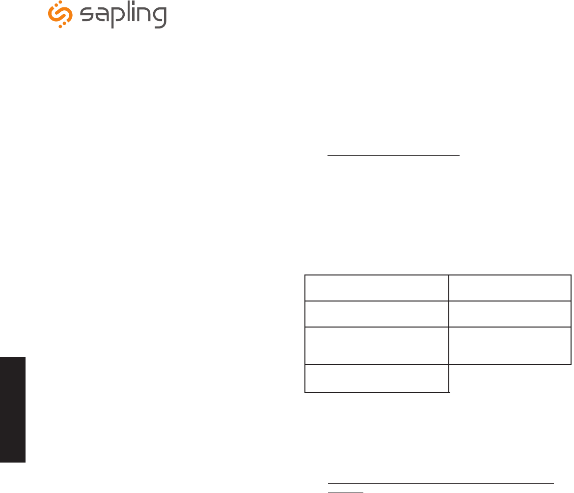
Windows 7
1. Insert the USB to RS485 converter into a USB connector port.
Note: If computer does not recognize the USB to RS485 converter after it is plugged in, unplug the converter, rotate it and plug it back into the
USB port.
2. Plug in the USB to RS485 converter into the J7 port on the board, located on the back of the digital clock.
3. Power up the digital clock.
4. Computer will indicate ‘Found New Hardware.’
5. It will then display, ‘New Hardware Installed.’
6. Next, click on Start menu --> Control Panel --> Hardware and Sound.
7. Click on “Device Manager” under Devices and Printers.
Installing the sbdconfig.exe Software
*Instructions continued on next page
Software
Note: The sbdconfig.exe software only works with the SBD 3200 or 3300 series.
Note: Sapling’s USB to RS485 converter needs to be purchased separately. Other USB to 485 converters will not work.
The Sapling Company, Inc.
1633 Republic Road
Huntingdon Valley, PA 19006
USA
+1 215.322.6063 P.
+1 215.322.8498 F.
www.sapling-inc.com
23
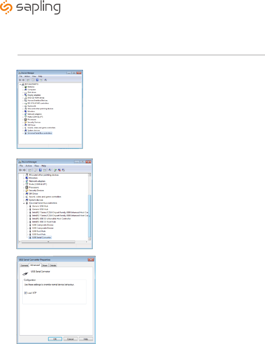
Installing the sbdconfig.exe Software (continued)
8. Scroll down to Universal Serial Bus controllers and click the + sign to open.
9. Double-click on the USB Serial Converter. A new window will open.
10. Click in the Advanced tab and check the box next to ‘Load VCP’ and click OK.
*Instructions continued on next page
The Sapling Company, Inc.
1633 Republic Road
Huntingdon Valley, PA 19006
USA
+1 215.322.6063 P.
+1 215.322.8498 F.
www.sapling-inc.com
24
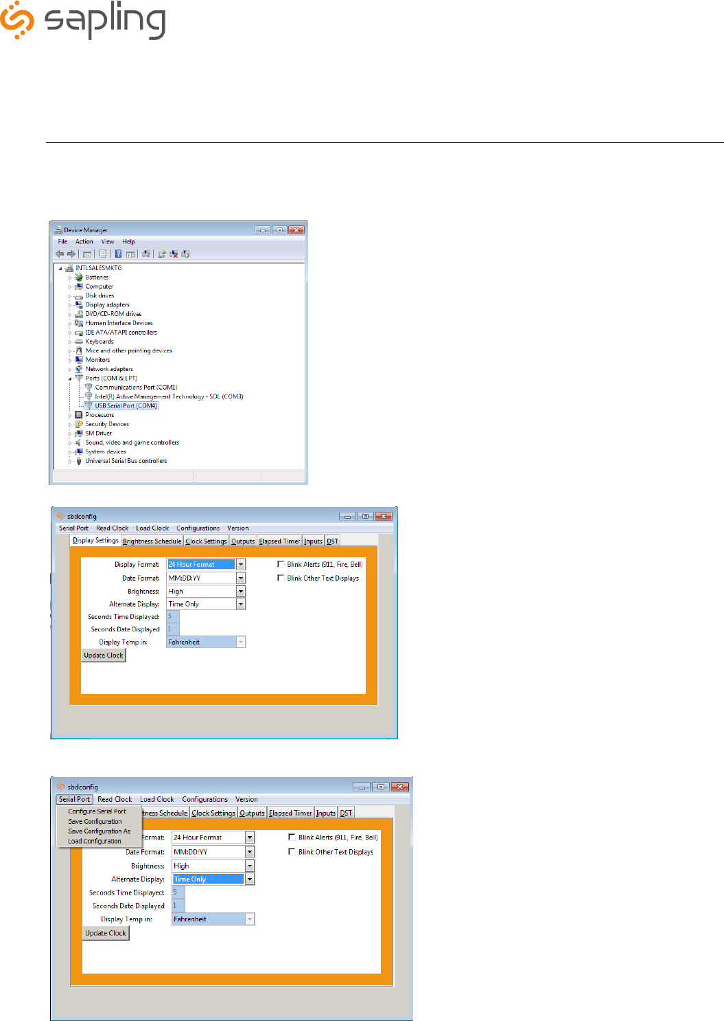
Installing the sbdconfig.exe Software (continued)
*Instructions continued on next page
13. Load the sbdconfig.exe software from disk (provided with the digital clock) or copy the software to the desktop.
14. Open the SBD config software, click on Serial Port (in the menu bar) --> Configure Serial Port. Match the Com port on the SBD config software
to the USB Serial Port in the Device Manager.
12. Open the Device Manager and scroll to Ports. Make note of what port the USB Serial Port is assigned to. For example: (COM 4).
11. Remove RS485 device from the USB port, wait 5 seconds and plug back into USB port.
The Sapling Company, Inc.
1633 Republic Road
Huntingdon Valley, PA 19006
USA
+1 215.322.6063 P.
+1 215.322.8498 F.
www.sapling-inc.com
25
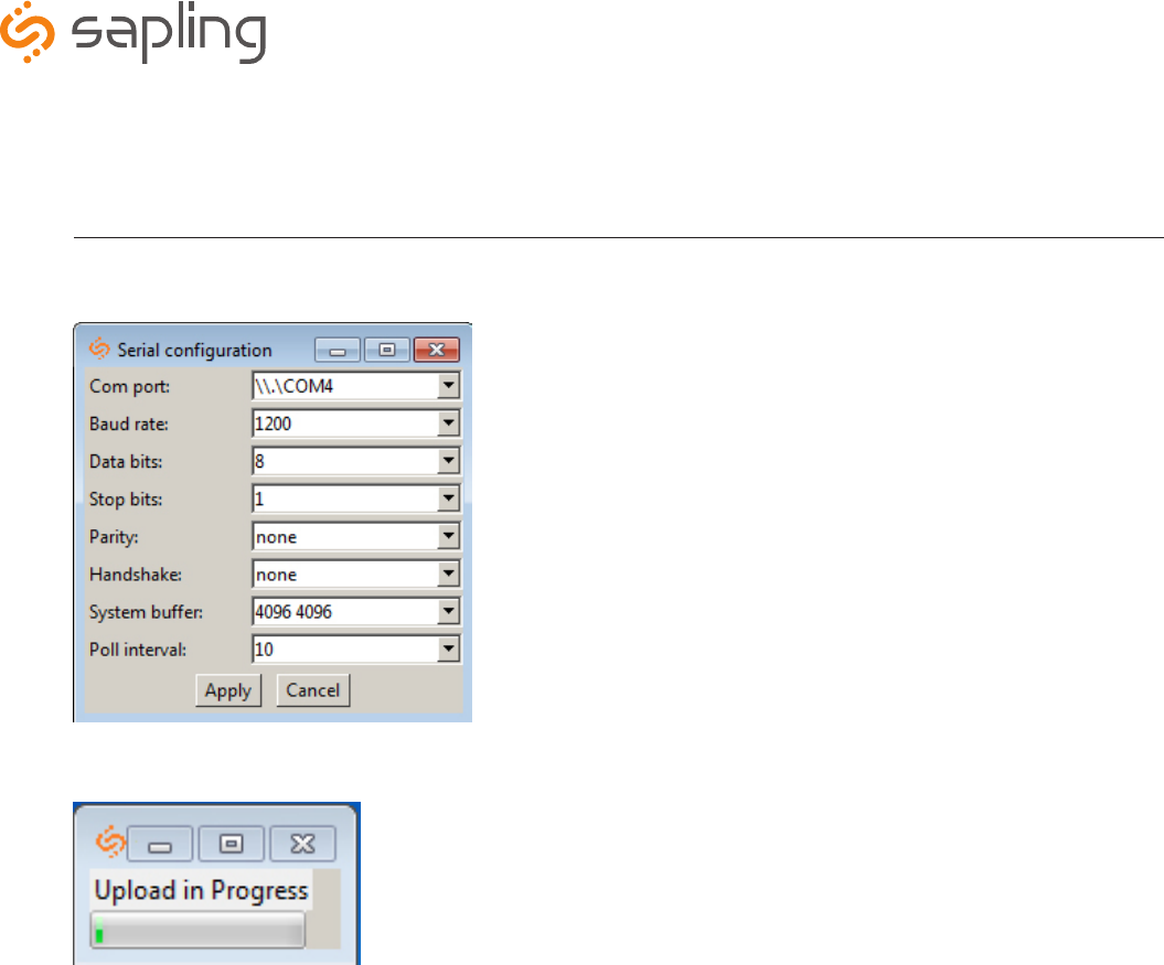
Installing the sbdconfig.exe Software (continued)
15. When Com ports match, click apply. The SBD 3000 settings are ready to be configured.
16. Click the ‘Read Clock’ button. The default settings will populate the tabs on the SBD config software. Once the ‘Read Clock’ button is clicked,
another window will open that will signify the upload process
The Sapling Company, Inc.
1633 Republic Road
Huntingdon Valley, PA 19006
USA
+1 215.322.6063 P.
+1 215.322.8498 F.
www.sapling-inc.com
26
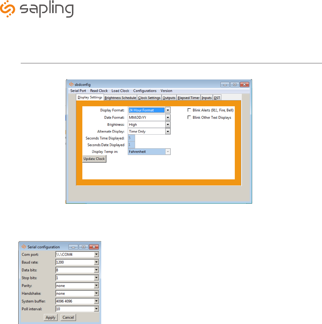
Sbdconfig Software - Task Bar Functionality
1. Serial Port
• Configure Serial Port: When clicked, this option will open the settings for the serial port (Fig. 1). This is where a user can manage the
settings that connect a PC to the digital clock.
Located on the task bar of the Sbdconfig software, there are five options to choose from: Serial Port, Read Clock, Load Clock, Configurations, and
Version.
• Save Configuration: After a user sets the serial port’s settings on the Sbdconfig software, this option will save a particular configuration
to a computer in order to upload it to a different clock.
• Save Configuration As: If a user modifies the serial port’s settings, this option will save a copy of the reconfigured clock to a computer.
• Load Configuration: This option allows a user to upload a previously saved serial port’s configuration to the Sbdconfig software. Once a
digital clock is connect to a computer via the USB to RS485 converter, click the ‘Load Configuration’ option.
Note: When any of the above options listed under the Serial Port tab are selected, they only apply to the Serial Configuration settings.
(Fig. 1)
The Sapling Company, Inc.
1633 Republic Road
Huntingdon Valley, PA 19006
USA
+1 215.322.6063 P.
+1 215.322.8498 F.
www.sapling-inc.com
27
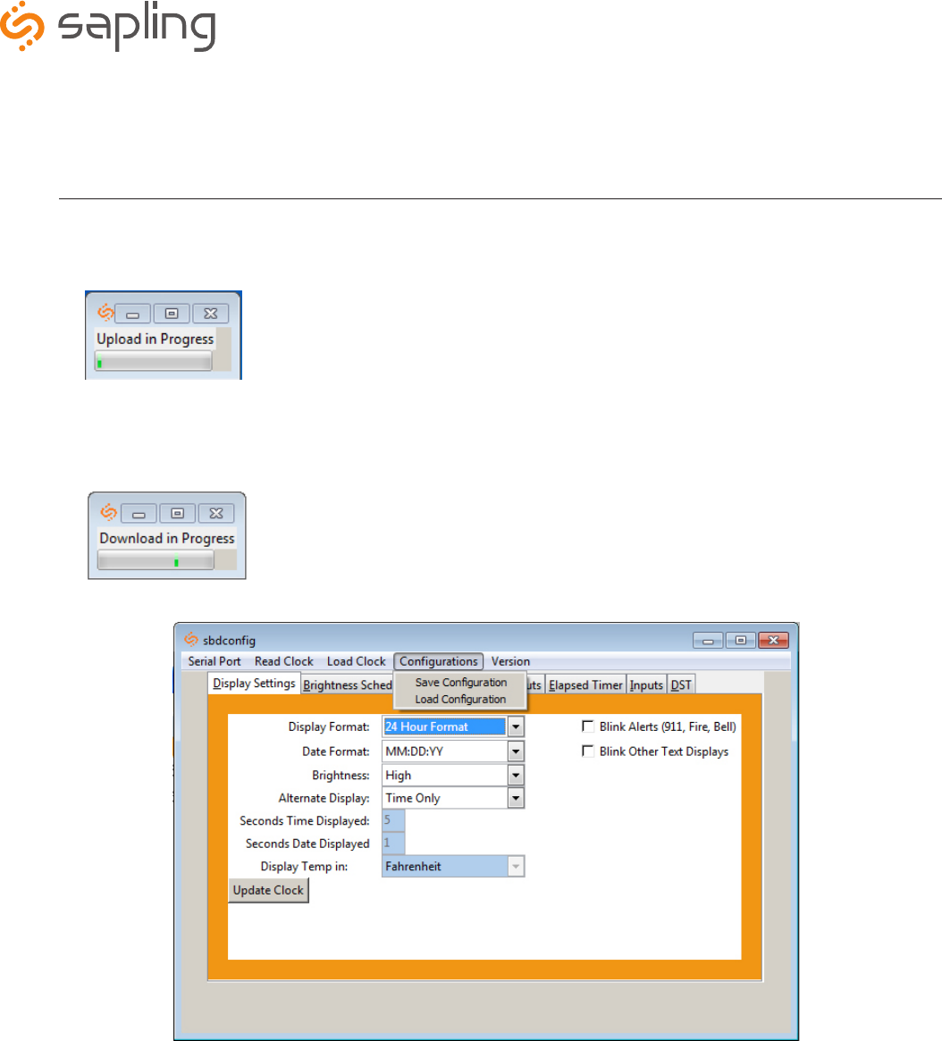
Sbdconfig Software - Task Bar Functionality (continued)
4. Configurations
• Save Configuration: After the clock’s settings are chosen, this option will save the configuration to a computer.
• Load Configuration: This option will allow a user to load the previously saved configuration from the computer.
2. Read Clock
• If a user has a previously configured clock and connects it to a computer, this option will read and upload the settings to the Sbdconfig
software program. Once the ‘Read Clock’ button is clicked, another window will open that will signify the upload process (Fig. 2).
• The ‘Load Clock’ button will allow a user to change multiple settings within the SBD config software tabs. This eliminates the need to
click ‘Update Clock’ on each screen. When the ‘Load Clock’ button is clicked, another window will open showing that the download is in
progress (Fig. 3).
3. Load Clock
(Fig. 2)
(Fig. 3)
5. Version
• The Version button displays the number of the software version.
The Sapling Company, Inc.
1633 Republic Road
Huntingdon Valley, PA 19006
USA
+1 215.322.6063 P.
+1 215.322.8498 F.
www.sapling-inc.com
28
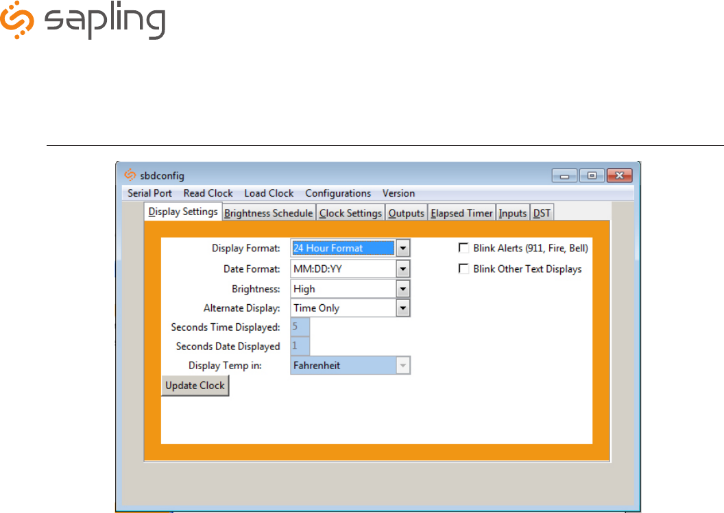
Sbdconfig Software - Display Settings
• Display Format: This option will allow the user to select how the time is displayed on the clock. There are two options: 12
hour format or 24 hour format.
• Date Format: This option sets the date to display in either American style: MM:DD:YY or European style: DD:MM:YY. For 4
digit clocks, the date will display in either American style: MM:DD or European style: DD:MM.
• Brightness: This option sets the brightness level that the clock will display. There are four options to choose from: High,
Medium, Low or Off.
• Alternate Display: This option allows a user to enable or disable an alternating display between time and date or time and
temperature.
• Seconds Time Displayed: If the Alternate Date/Time function is enabled, this option allows a user to input how many
seconds the time is on display.
• Seconds Date/Temp Displayed: If the Alternate Date/Time or Alternate Time/Temperatutre function is enabled, this option
allows a user to input how many seconds the Date or Temperature is on display.
• Blink Alerts (911, Fire, Bell): When checked, this option will enable the emergency alert options programmed with the
master clock to blink when activated (see the specific master clock user manual for more information).
• Blink Other Text Displays: When checked, this option will enable any other messages programmed with the master clock
to blink when activated (see the specific master clock user manual for more information).
Note: If the Blink Alerts (911, Fire, Bell) and/or the Blink Other Text Displays options are left unchecked, they will display solid text
when enabled.
1. Clicking on the Display Settings tab will allow a user to program the following settings:
2. Once all of the Display Settings are chosen, click the ‘Update Clock’ button to store the selected options or, when all the tabs have been
programmed, click the ‘Load Clock’ button located on the menu bar to store all options.
The Sapling Company, Inc.
1633 Republic Road
Huntingdon Valley, PA 19006
USA
+1 215.322.6063 P.
+1 215.322.8498 F.
www.sapling-inc.com
29
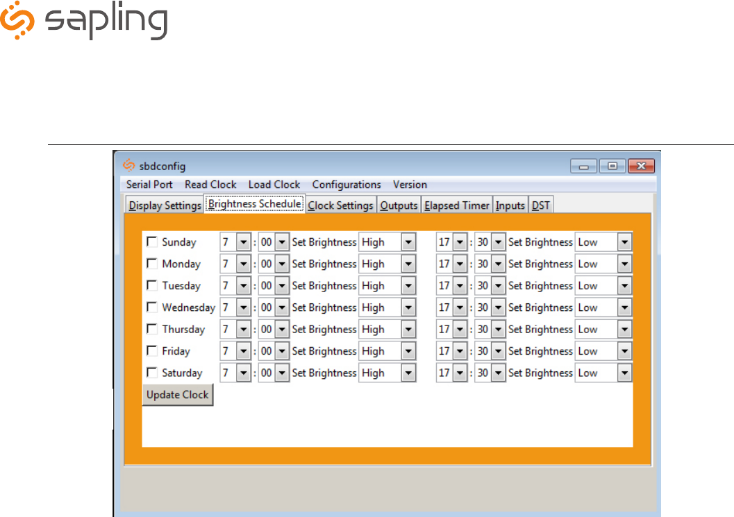
Sbdconfig Software - Brightness Schedule
1. Clicking on the Brightness Schedule tab will allow a user to establish a Brightness Schedule for the digital clock(s). This includes choosing the
day(s) to set alternate brightness levels, the time of day the brightness level will change and the level of brightness the clock will display (High,
Medium, Low or Off). In addition, a user has the option to schedule a second time during a selected day that they would like to adjust the
brightness level of the clocks.
2. Once the Brightness Schedule has been programmed, click the ‘Update Clock’ button to store the selected options or when all the tabs have
been programmed, click the ‘Load Clock’ button located on the menu bar to store all options.
The Sapling Company, Inc.
1633 Republic Road
Huntingdon Valley, PA 19006
USA
+1 215.322.6063 P.
+1 215.322.8498 F.
www.sapling-inc.com
30
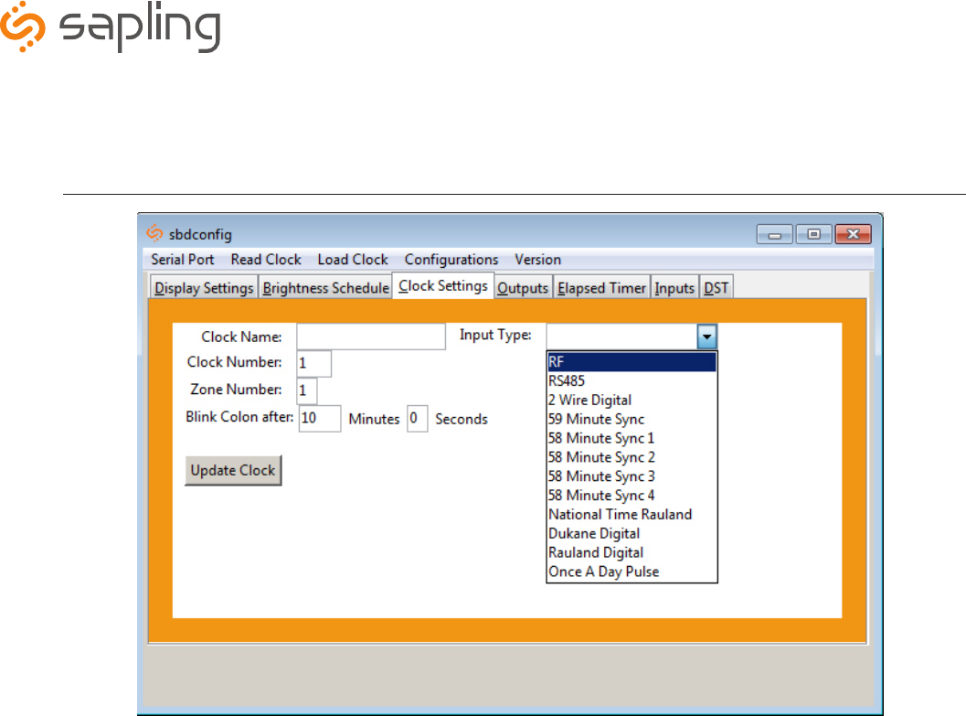
Sbdconfig Software - Clock Settings
• Clock Name: This option allows a user to assign the clock a unique name, such as its location in a facility. The name cannot
exceed 24 characters.
• Clock Number: This option allows a user to assign a unique number to a clock. The user can choose the clock number. Please
reference the master clock manual associated with your system for more information.
• Zone: This option allows a user to choose the clock’s zone. A zone is a collection or grouping of clocks within a certain section of
a facility. Here, a user will input a number (1-99) to designate the zone of the clock.
• Blink Colon After: The colon on the digital clock display has the ability to blink in order to signify a loss of communication
with the master clock. This option will let the user choose how many seconds a clock is without communication before the colon
starts to blink.
• Input Type: This option allows a user to choose what type of sync input for correction mode on the clock.
1. Clicking on the Clock Settings tab will allow a user to program the following settings:
2. Once all of the Clock Settings are chosen, click the ‘Update Clock’ button to store the selected options or when all the tabs have been
programmed, click the ‘Load Clock’ button located on the menu bar to store all options.
The Sapling Company, Inc.
1633 Republic Road
Huntingdon Valley, PA 19006
USA
+1 215.322.6063 P.
+1 215.322.8498 F.
www.sapling-inc.com
31
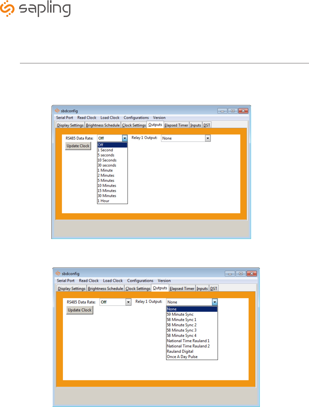
Sbdconfig Software - Outputs
• RS485 Data Rate: This option determines how often data (time and date) is sent to the clock(s) or other Sapling devices, such
as Wireless Repeaters, Converter Boxes or other Master Clocks.
1. Clicking on the Outputs tab will allow a user to program the following settings:
2. Once the Relay 1 Output settings are chosen, click the ‘Update Clock’ button to store the selected options or when all the tabs have been
programmed, click the ‘Load Clock’ button located on the menu bar to store all options.
• Relay 1 Output: This option allows a user to choose the time sync the clock uses to correct other time keeping devices, such
as paging systems, an existing master clock and other devices manufactured by different companies. Refer to page 18 for wiring
information and page 26 for an explanation of each output type.
The Sapling Company, Inc.
1633 Republic Road
Huntingdon Valley, PA 19006
USA
+1 215.322.6063 P.
+1 215.322.8498 F.
www.sapling-inc.com
32
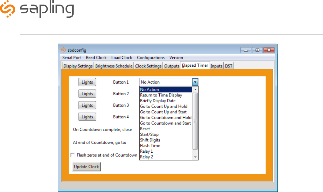
Sbdconfig Software - Elapsed Timer (3200/3300 Versions)
On the Elapsed Timer tab, there are four buttons available to program. Each option has different functionality to meet your needs.
1. Program the first button on the Elapsed Timer by selecting one of the options in the drop down list next to Button 1. Listed below are the
options and what their functionality is:
• No Action: Choosing this option will perform no functions.
• Return to Time Display: This option will cause the digital clock to return to the current time display, regardless of what function it is
currently displaying.
• Briefly Display Date: This option will change the clock’s display to briefly show the date when the current time is on display. This
option will not work in count up or count down mode.
• Go to Count Up and Hold: This option will cause the digital clock to hold at zero and wait for the count up to start. Press the button
programmed for Start/Stop to begin Count Up.
• Go to Count Up and Start: This option will make the clock display the count up function and begin counting up from zero, as soon as
the button is pushed.
• Go to Count Down and Hold: This option will cause the digital clock to hold at the specified count down start time and wait for the
function to start. Press the button programmed for Start/Stop to begin Count Down.
• Go to Count Down and Start: This option will make the clock display the count down function and begin counting down from a
specified time, as soon as the button is pushed.
• Reset: This option will cause the timer to rest the last-used Count Down or Count Up.
• Start/Stop: This option will cause the timer to start or stop its counting function.
• Shift Digits: This option will cause the digits to shift from an Hour/Minutes display to a Minutes/Seconds display
(4 digit digital clocks only).
• Flash Time: This option will enable the time to flash for 2 seconds when a count down is in progress.
• Relay 1: This option will cause the relay contact closure to close for a specified number of seconds (3300 Series Only).
• Relay 2: This option will cause the relay contact closure to close for a specified number of seconds (3300 Series Only).
• Code Blue: This option enables a special purpose Count Up. When the designated button is pressed the first time, a Count Up will
begin. When pressed again, the Count Up will pause. When pressed and held, the Count Up will clear and the display will go back to
showing the time. This overrides the interface lights, so that the interface is green while the time is running, and red when the timer has
been paused.
*Instructions continued on next page
Note: The default options for the Elapsed Timer are No Action.
Note: It is recommended that a user program one of the buttons with the Start/Stop option.
Note: If Relay 1 is used for an Output Sync, it cannot be used with the Elapsed Timer.
The Sapling Company, Inc.
1633 Republic Road
Huntingdon Valley, PA 19006
USA
+1 215.322.6063 P.
+1 215.322.8498 F.
www.sapling-inc.com
33
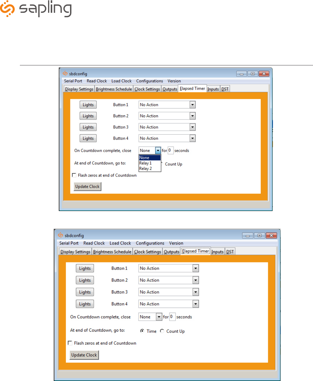
Sbdconfig Software - Elapsed Timer (3200/3300 Versions) (continued)
• On countdown complete, close: This option allows a user to choose how many seconds the relay will be closed for. The
maximum number of seconds is 9.
*Instructions continued on next page
• At end of Countdown, go to: When a countdown completes, this option allows a user to choose between having the clock
display either the time or starts a count up.
• Flashes zeros at end of countdown: When checked, this option enables zeros to flash on the clock’s display after a
countdown has completed. The zeros will flash for 5 seconds after countdown is complete.
The Sapling Company, Inc.
1633 Republic Road
Huntingdon Valley, PA 19006
USA
+1 215.322.6063 P.
+1 215.322.8498 F.
www.sapling-inc.com
34
Sbdconfig Software - Elapsed Timer (3200/3300 Versions) (continued)
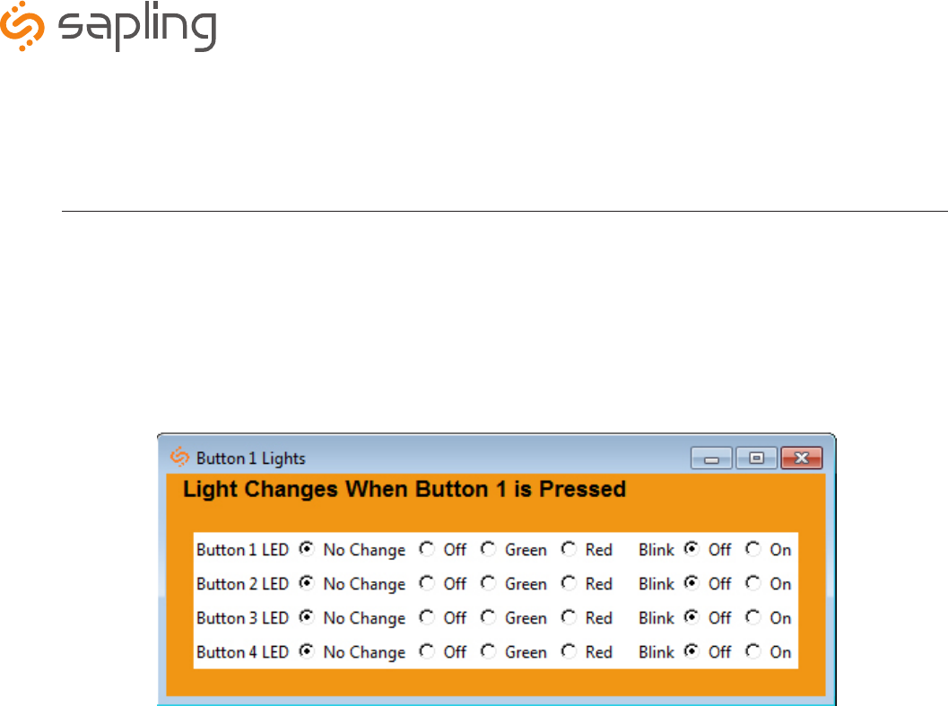
2. Program the ‘Lights’ settings that will display on the Elapsed Timer when a particular button is pushed. The lights on the Elapsed Timer must be
programmed separately for each button. The lights on the Elapsed Timer will only turn off if the user configures it into the buttons. Listed below
are the options and their functionality:
Note: When configuring the lights for a specific button, any changes made to the light functions of the remaining three buttons are only affected
when the selected button is pushed. E.g. If the button 1 lights dialog box is open, adjusting the lights on buttons 2,3 and 4 will only have an affect
when button 1 is pushed.
• No Change: When selected, a particular button’s settings will remain unaltered from its previous selected state.
• Off: This option will turn off the lights on a particular Elapsed Timer button.
• Green / Red: This option allows the user to choose either green or red backlighting on the Elapsed Timer when the button is pressed.
• Blink On / Off: This option will allow the user to turn on or off the light blinking function. When this is set to Off, the backlight will
stay on. When this is set to On, the backlight will blink.
3. Repeat steps 1 and 2 for the three remaining lights buttons.
4. After all four buttons and the lights buttons on the Elapsed Timer are set, click the ‘Update Clock’ button to store the selected options or when all
the tabs have been programmed, click the ‘Load Clock’ button located on the menu bar to store all options.
The Sapling Company, Inc.
1633 Republic Road
Huntingdon Valley, PA 19006
USA
+1 215.322.6063 P.
+1 215.322.8498 F.
www.sapling-inc.com
35
Sbdconfig Software - Inputs (3300 Series)
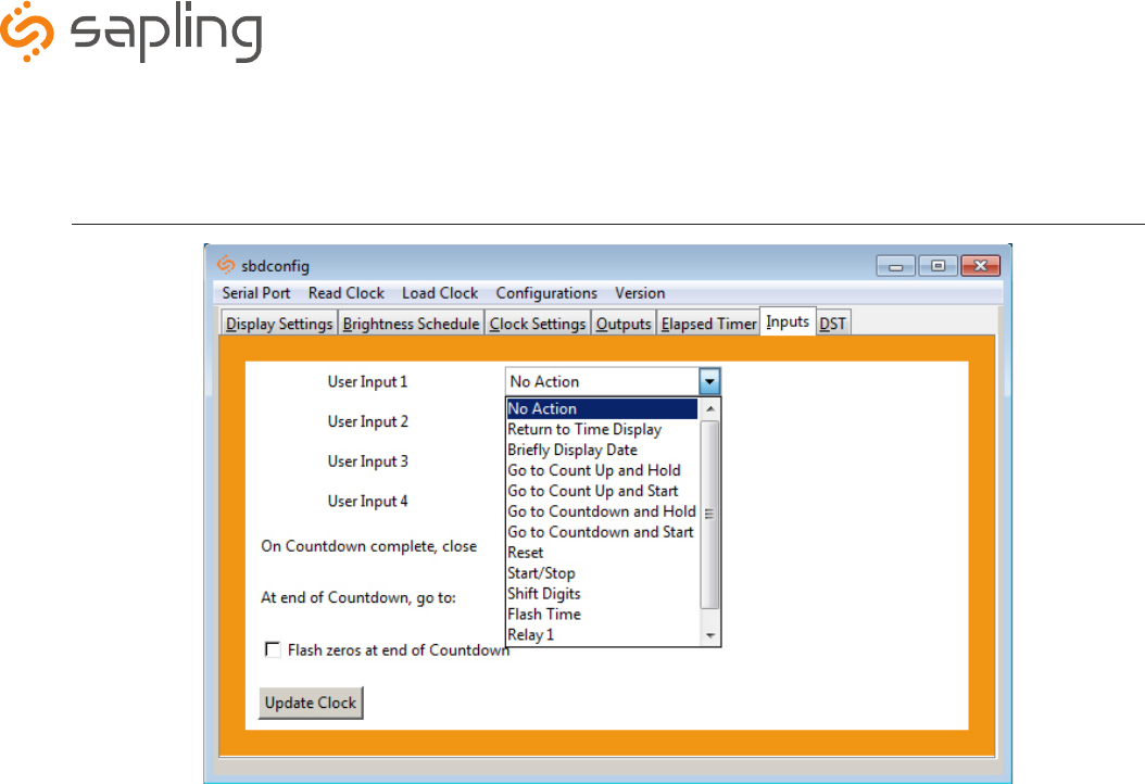
1. The ‘Inputs’ tab allows a user to program the clock to perform a certain function through a switch or relay contact closure from an outside
device such as Code Blue, Nurses Call, etc. Program the first Input on the SBD 3300 by selecting one of the options in the drop down list next to
Input 1. Listed below are the options and what their functionality is:
• No Action: Choosing this option will perform no functions on the digital clock.
• Return to Time Display: This option will cause the digital clock to return to the current time display, regardless of what function it is
currently displaying.
• Briefly Display Date: This option will change the clock’s display to briefly show the date when the current time is on display. This
option will not work in count up or count down mode.
• Go to Count Up and Hold: This option will cause the digital clock to hold at zero and wait for the count up to start. A Start/Stop
input needs to be applied to begin Count Up.
• Go to Count Up and Start: This option will make the clock display the count up function and begin counting up from zero, as soon as
the button is pushed.
• Go to Count Down and Hold: This option will cause the digital clock to hold at the specified count down start time and wait for the
function to start. A Start/Stop input needs to be applied to begin Count Down.
• Go to Count Down and Start: This option will make the clock display the count down function and begin counting down from a
specified time, as soon as the button is pushed.
• Reset: Resets last used Count Down or Count Up.
• Start/Stop: This option will cause the timer to start or stop its counting functions.
• Shift Digits: This option will cause the digits to shift from an Hour/Minutes display to a Minutes/Seconds display
(4 digit digital clocks only).
• Flash Time: This option will enable the time to flash for 2 seconds when a countdown is in progress.
• Relay 1: This option will cause the relay contact closure to close for a specified number of seconds (3300 Series Only).
• Relay 2: This option will cause the relay contact closure to close for a specified number of seconds (3300 Series Only).
*Instructions continued on next page

The Sapling Company, Inc.
1633 Republic Road
Huntingdon Valley, PA 19006
USA
+1 215.322.6063 P.
+1 215.322.8498 F.
www.sapling-inc.com
36
Sbdconfig Software - Inputs (continued)
• On countdown complete, close: This option allows a user to choose how many seconds the relay will be closed.
• At end of Countdown, go to: When a countdown completes, this option allows a user to choose between having the clock
display either the time or start counting up.
2. Once all of the Input settings are chosen, click the ‘Update Clock’ button to store the selected options or when all the
tabs have been programmed, click the ‘Load Clock’ button located on the menu bar to store all options.
The Sapling Company, Inc.
1633 Republic Road
Huntingdon Valley, PA 19006
USA
+1 215.322.6063 P.
+1 215.322.8498 F.
www.sapling-inc.com
37
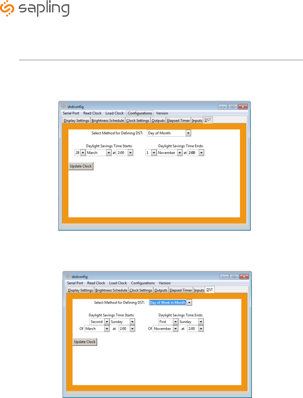
Sbdconfig Software - DST
• Day of Week in Month: When this option is selected, Daylight Saving Time can be chosen based on what week in what
month and what time it begins and ends. For example, Daylight Saving Time can begin on the second Sunday in March at
2AM and ends on the first Sunday in November at 2AM. (Fig. 5)
Fig. 5
• Select Method for Defining DST: This drop down allows a user to choose between four options for Daylight Savings Time.
• Day of Month: When this option is selected, Daylight Saving Time can be chosen based on what date and time it begins
and ends. For example, Daylight Saving Time can begin on March 28 at 2AM and end on November 1st at 2AM. (Fig. 4.)
Fig. 4
The Sapling Company, Inc.
1633 Republic Road
Huntingdon Valley, PA 19006
USA
+1 215.322.6063 P.
+1 215.322.8498 F.
www.sapling-inc.com
38
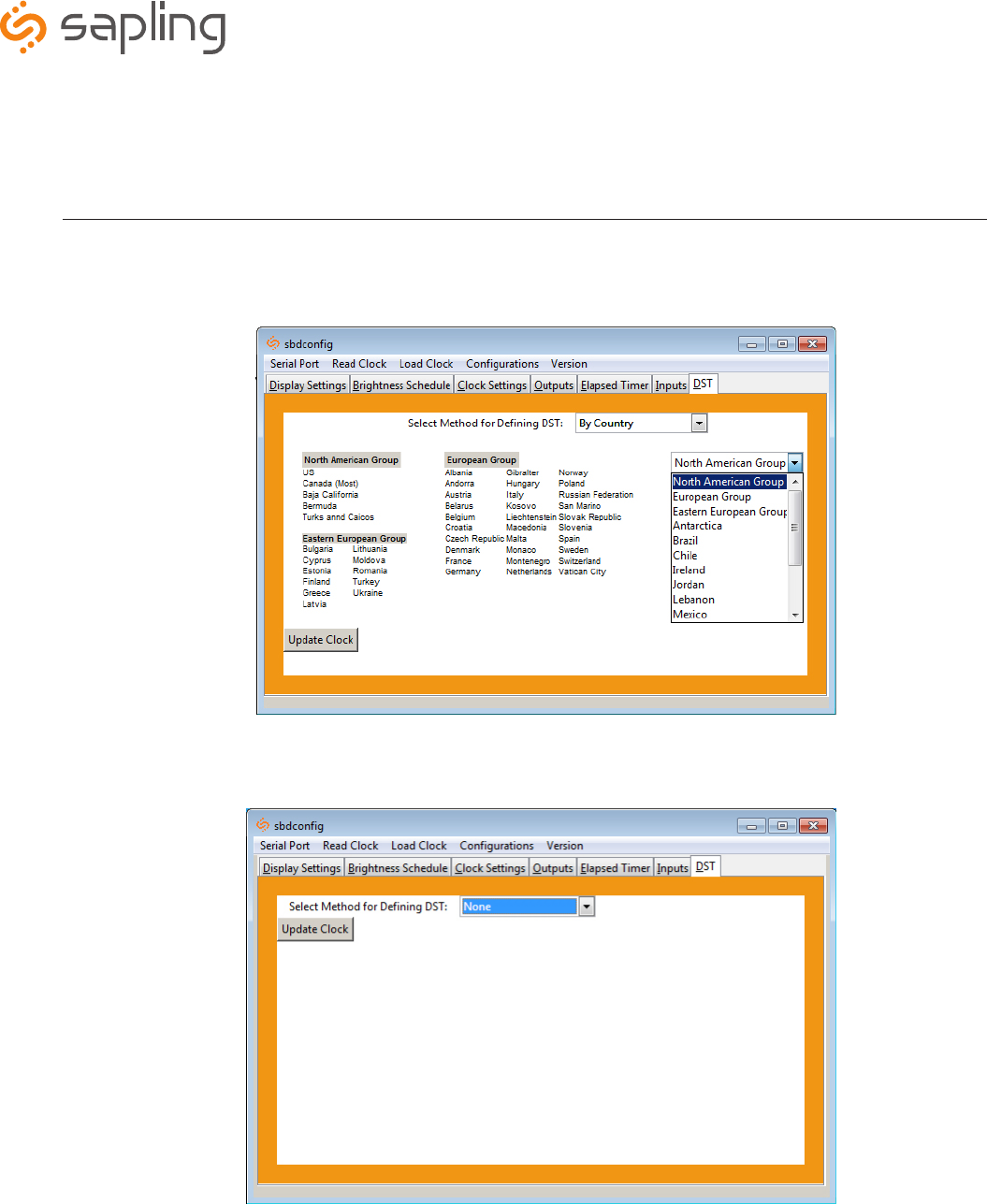
Sbdconfig Software - DST (continued)
2. Once all of the DST settings are chosen, click the ‘Update Clock’ button to store the selected options or when all the tabs have been
programmed, click the ‘Load Clock’ button located on the menu bar to store all options.
• By Country: When this option is selected, Daylight Saving Time can be chosen by country. For example, Daylight Saving Time can be
selected to follow the DST rules established in the United States. (Fig. 6)
• None: When this option is selected, Daylight Saving Time is not applied. (Fig. 7)
Fig. 6
Fig. 7

The Sapling Company, Inc.
1633 Republic Road
Huntingdon Valley, PA 19006
USA
+1 215.322.6063 P.
+1 215.322.8498 F.
www.sapling-inc.com
39
Frequently Asked Questions
Will the clock cause interference with any of my other wireless devices?
No, the SBL Series wireless clock works on 915 - 928 MHz frequency-hopping technology. The clock switches frequencies automatically when the
receiver and transmitter are open, thus interference is avoided.
How long does it take for the clock to receive a signal?
Upon power up, the clock will look for the signal for 30 minutes. The SBL Series wireless clock will look for the signal every minute thereafter.
What happens to the SBL 3300 if a power failure occurs?
Unlike some clocks that require a 9 volt battery for time keeping, the SBL 3300 comes equipped with a 10 year battery backup (only available with
the 3300 Series). Upon restoration of power, the SBL 3300 immediately corrects itself from its built-in time base. This occurs within seconds of
“power-up.” Clocks which do require a 9 volt battery backup risk having the battery die during extended shut downs. Each individual clock must
then be opened in order to replace the battery. Since the SBL 3300 includes a 10 year battery backup, the clock never needs to be opened.
How do I take advantage of the SBL 3200 or 3300 chronograph functions?
Sapling’s Elapsed Timer controls all chronograph functions of the SBL 3200/3300 and must be ordered for this functionality to work. The display
can be programmed to show either HH:MM or MM:SS (4 digit digital clock) or HH:MM:SS (6 digit digital clock), and the readout can count up from
00:00:00 to 99:59:59 or count down with a programmable starting point from 99:59:59 to 00:00:00, with interrupt and resume capabilities.
How can I display “BELL” and “FirE” on the clock?
“BELL” displays can be programmed by either the Sapling 2000 or 3000 Series Master Clocks. To display “FirE”, a 3000 Series Master Clock, which
receives a signal from an existing alarm system, must be used .
I have double mount clocks and only one clock got the signal.
If only one clock gets the signal check the connection from the two clocks. Only one clock should be connected to the wireless transceiver; the
other clock gets the time via the RS485 data cable. Make sure the clock that is connected to the wireless board has the RS485 cable with the
purple and brown wires connected to P2, if not flip around the cable.
Do the SBL wireless clocks work together with SAL Series analog wireless clocks?
Yes, the SBL Series wireless clocks work integrally with Sapling’s SAL Series wireless analog clocks.
Support
Support

The Sapling Company, Inc.
1633 Republic Road
Huntingdon Valley, PA 19006
USA
+1 215.322.6063 P.
+1 215.322.8498 F.
www.sapling-inc.com
40
Troubleshooting
The clock is not running. What do I do?
a) Measure the input voltage to the clock. The voltage should measure 85-135 volts in the 110 volt model or 10-28 volts in the 2.5”/24 volt
model and 16-28 volt in the 4.0”/24 volt model.
b) Make sure the transformer is an isolated transformer if using a 24 volt model.
c) Make sure the ground wire is not touching other wires.
NOTE: If you fail to follow instructions b and c listed above, the fuses can be blown.
What happens if the clock does not receive the signal?
Take the clock within close proximity to the transmitter and power the clock. If the clock does not correct, call Sapling technical support.
I have a location with a marginal signal. What should I do?
Try to install a repeater, part number SMA-1SR-0000-1 in a nearby area to the location or install a 110 volt clock.
Support
Support

The Sapling Company, Inc.
1633 Republic Road
Huntingdon Valley, PA 19006
USA
+1 215.322.6063 P.
+1 215.322.8498 F.
www.sapling-inc.com
41
FCC Statements
The Federal Communications Commission (FCC) wants you to know:
This equipment has been tested and found to comply with the limits for a Class B digital device, pursuant to Part 15 of the FCC rules. These limits
are designed to provide reasonable protraction against harmful interference in a commercial installation. This equipment generates, uses, and
can radiate radio frequency energy and, if not installed and used in accordance with the instructions, may cause harmful interference to radio
communcations. However, there is no guarantee that interference will not occur in a particular installation. If this equipment does cause harmful
interference to radio or television reception, which can be determioned by turning the equipment off and on, the user is encouraged to try to
correct the interference by one or more of the following measures:
• Reorient or relocate the receiving antenna.
• Increase the separation between the equipment and receiver.
• Connect the equipment to an outlet on a circuit different from which the receiver is connected.
• Consult the dealer or an experienced radio/TV technician.
FCC Warnings:
Modifications not expressly approved by the manufacturer could void the user authority to operate the
equipment under FCC Rules.
For the 900 MHz Model, FCC ID Number: R73LPA1
This equipment must be installed by professional installers only. For precautionary measures, the FCC
requires a minimum distance of 3 cm form the clock to constant human physical exposure. The antenna
has a maximum gain of 5.14 dB.
For the 2.4 GHz Model, FCC ID Number: R73MOD-24G-1
The antenna(s) used for this transmitter must be installed to provide a separation distance of at least 5.78
cm from all persons and must not be co-located or operating in conjunction with any other antenna or
transmitter.
Support
Support

The Sapling Company, Inc.
1633 Republic Road
Huntingdon Valley, PA 19006
USA
+1 215.322.6063 P.
+1 215.322.8498 F.
www.sapling-inc.com
42
Support
Index
12/24 Hour Format 14, 17
58 Minute Correction 19
59 Minute Correction 19
Alternate Time/Date 15, 27
American Date Style 15, 27
Blink Alerts 27
Brightness 15, 17, 27, 28
Brightness Schedule 15, 28
Clock Name 29
Clock Number 15, 29
Clock Settings 29
COM Port 23, 24
Configuration 9, 10, 11, 25, 26
Countdown 32, 34, 35
Count Up 31, 32, 34, 38
Daylight Saving Time 14, 36, 37
Device Manager 22, 23
Diagnostics 20
Diagnostic Mode 20
Display Settings 27
Double Mount 6, 7, 8, 38
Dukane 11, 19
Elapsed Timer 10, 11, 31, 32, 33, 38
European Date Style 15, 27
‘Found New Hardware’ 21
Installation 3, 4, 5, 6, 7, 8
Intercom 12
Jumpers 9, 10, 11, 17
Jumper Settings 5, 8, 9, 10, 11
Jumper Position 9, 10, 11
Load Clock 25, 26, 27, 28, 29, 30, 33, 35, 37
Loss of Communication 16, 29
Loss of Communication Alert 16
Master Clock 15, 16, 20, 27, 29, 30, 38
National Time/Rauland 17, 19
‘New Hardware Installed’ 21
Once-A-Day Pulse 17, 18, 19
Output Type 30
Power Settings 9, 10, 11
Support

The Sapling Company, Inc.
1633 Republic Road
Huntingdon Valley, PA 19006
USA
+1 215.322.6063 P.
+1 215.322.8498 F.
www.sapling-inc.com
43
Programming 14, 15, 16, 17, 18,
19, 20, 21
Programmable Relay 18
Rauland 18, 20
Read Clock 25, 26, 27
Relay 11, 12, 18, 19, 20, 32,
33, 35, 36
RS485 9, 10, 11, 17, 22, 24,
26, 31, 39
Sbdconfig 22, 23, 24, 25, 26, 27,
28, 29, 30, 31, 32, 33,
34, 35, 36, 37, 38
Sbdconfig.exe 22, 23, 24, 25
Serial Port 24, 26
Surface Mount 3
Task Bar 26, 27
USB to RS485 22, 26
Wiring 5, 7, 8, 9, 10, 11, 12
18, 31
Zone 16, 30
Zone Number 16
Support
Index
Support