Thermo King TKW40815 PCS1900 MHz vehicle tracking system User Manual 40 815
Thermo King Corporation PCS1900 MHz vehicle tracking system 40 815
Contents
- 1. Installation Guide with statements
- 2. Web based USer Guide
Installation Guide with statements

THERMO KINGTHERMO KING
KITKIT
Subject: Trac-King GSM
Units: SB units
Benefits: This kit contains the parts needed to install the system
40-815
40-815 (1/03 JJ)
Kit Contents:
1 92-2619 Antenna Mounting Bracket 1
2 92-2672 Unit Mounting Brackets 2
3 NSS Trac-King Unit. 1
4 NSS Antenna (GSM/GPS) with nut 1
5 41-5168 Trac-King harness 1
6 55-2977 Screw - bracket 2
7 55-1800 Lockwasher 2
8 55-2086 Flatwasher 2
9 55-7767 Insert - threaded 2
10 55-9756 Rivet - bracket 2
11 55-2201 Flatwasher 16
12 203-498 Wipe (Alcohol) 1
13 55-1844 Screw 8
14 55-4223 Nut 8
Installation Instructions:
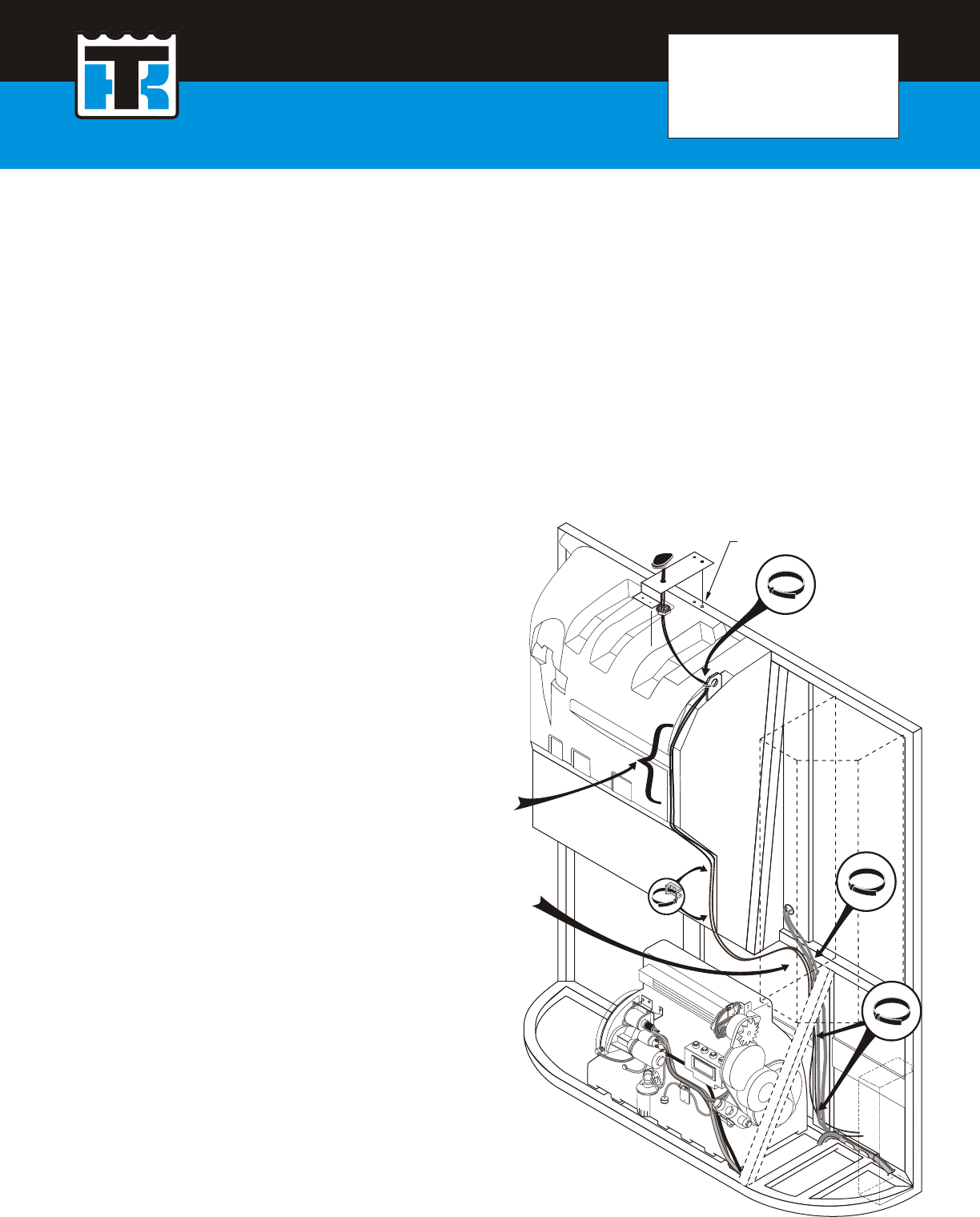
1. Attach antenna to the mounting bracket with the provided nut.
2. Mount the antenna assembly to the center of the condenser frame. Use the bracket as a template to
mark and drill two 25/64 (10 mm)for the threaded inserts. Loosely attach the antenna assembly with
the supplied screws, flatwashers and lockwashers.
3. Clean the plastic bulkhead with isopropyl alcohol wet wipes (203-498). Wipe dry.
4. Peal off the protective tape (double sided) and firmly press the bracket to the plastic bulkhead.
Tighten hardware. Drill two 9/32 holes in the plastic bulkhead and install the rivets, seal the rivet
heads with silicone calk to protect the integrity of the bulkhead.
Do Not drill into
bulkhead, use caulk
to secure cables
Maintain 3 inches of
clearance between
the and mufflercables
Drill 25/64 (10 mm)
Application Guidelines: For maximum bond strength the
Ideal tape application is accomplished when temp. is
between 70 to 100 F and the bond is allowed to dwell
72 hours. The bond strength is dependent upon the
amount of adhesive-to-surface contact developed. Firm
application pressure develops better adhesive contact
and thus improves bond strength.
5. Route the antenna cables to the control box.
Bandwrap cables to the lifting eye. Secure antenna
cables to bulkhead with caulk.
6. Use bandwraps to secure the cables to the main
harness and enter the control box through the harness
grommet. Maintain 3 inches of clearance from the
muffler, belts and pulleys.

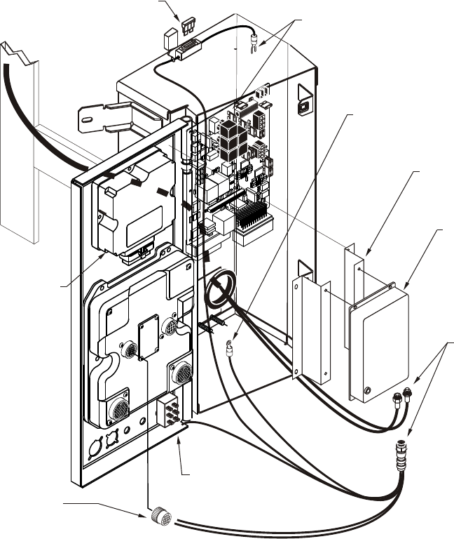
Attach GND wire to
ground stud
Attach 2S wire to
no. 2 terminal
Use brackets as a
template to mount the
moduleTrac-King
Solder IGN wire
to 8 wire on
On-Off switch
DAS Box
Communications Harness
(See instructions above)
Clamp and Strain Relief (40-633)
Connector (41-746)
3 Amp fuse
Trac-King module
Attach connectors
finger tight
5. Attach the brackets to the Trac-King module, position the assembly above the TG-IV controller, mark and drill
four (4) ¼ holes into the cover. The brackets must be used on units with or without DAS.
6 Attach the antenna cables and the seven pin connector to Trac-King module, hand tight.
7. Attach the GND wire with terminal to the control box ground stud.
8. Solder the IGN wire to the #8 wire terminal of the On/Off switch.
9. Attach the 2S wire to the #2 terminal on the relay board.
10. Use an Amp terminal remover tool (204-737) to remove the two wires from the Communication harness 14 pin
Amp connector (see below) and replace them with TxD and RxD wires.
Thermoguard µPIV/µPV, Multitemp µPIV
Trac-King Comm. Port Pin No.
TxD TxD2 1
RxD RxD2 2
Thermoguard µPVI (see Note 1) Thermoguard VI (see Note 2)
Trac-King Comm. Port Pin No. Trac-King Comm. Port Pin No.
TxD TxD3 11 TxD TxD1 8
RxD RxD3 14 RxD RxD1 4
or or
TxD TxD2 3 TxD TxD2 27
RxD RxD2 7 RxD RxD2 19
Note 1. Comm. Port 2 is an option if Comm. Port 3 is not available. For Port 3, configure it to REMC OFF and TRMR OFF (for Port 2) in
the super guarded access command.
Note 2. If installation configuration has no remote display but with DAS installed, connect the TRAC-king to Comm. Port 1. Otherwise to
Comm. Port 2.
11. Secure excess wires with bandwraps.
12. To test the unit refer to your user manual. Return the unit to service.
To retrieve a user manual got to http://www.trac-king.com, enter your username and password. Click on the book
with the question mark “?” on the cover (located to the far right of the TK Logo) and then click on download.

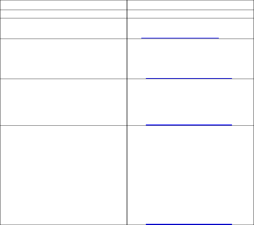
Basic Troubleshooting Guide
Symptom/Problem Action
1. No web access. Call Technical support
@ 952-887-2200/952-200-8389 or e-mail:
gsmtrac-king@thermoking.com
2. Position, time, date and refrigeration data
are not being displayed / web does not
respond.
Step 1: Check LED of the unit is flashing.
Step 2: Check fuse and power connection.
Step 2: Check GSM network coverage.
Step 3: Call Technical support
@952-887-2200/952-200-8389 or e-mail
gsmtrac-king@thermoking.com
3. Position, time and date are not displayed-
refrigeration data is available.
Step 1: Check if antenna has line-of-sight to the
Sky.
Step 2: Check damage to GPS antenna its
cable and hand tight connectors.
Step 3: Call Technical support
@ 952-887-2200/952-200-8389 or e-mail
gsmtrac-king@thermoking.com
4. Refrigeration data not displayed, position
time and date are available.
Step 1: Review TX/RX connection –check
trac-king loom cable.
Step 2: Reset power of the Trac-King GSM
Unit. Leave the power of the refrigeration
unit on.
Step 3: Check communication port. It should be
set to datapac protocol or
remote no/off. Refer to green book for
changes of settings.
Step 4: Verify from Table 1 if the software
version of the micro is supported by this
wireless product.
Step 5: Call Technical support
@ 952-887-2200/952-200-8389 or e-mail
gsmtrac-king@thermoking.com

Table 1
Controller Supported Software Revision Unsupported Software Revision
TGVI 1090 1060 and below
µP VI 4035
4032
4031
4030
Buzzer 4010 / 8888
µP V KOR 603
602
600
9607
611
610
601
µP IV Multi Zone (TCI) 2023
2022
2021
2015
2011
2001
µP IV+ Single Temp 612 310
510
512
3021
3022
9438
3020
420
412

Statement according FCC part 15.19
FCC identifier has to be on the equipment
This device complies with Part 15 of the FCC Rules. Operation is
subject to the following two conditions: (1) this device may not cause
harmful interference, and (2) this device must accept any interference
received, including interference that may cause undesired operation.
Statement according FCC part 15.21
Modifications not expressly approved by Thermo King Corp. could
void the user's authority to operate the equipment.
Statement according FCC part 15.105
NOTE: This equipment has been tested and found to comply with the limits for a
Class B digital device, pursuant to Part 15 of the FCC Rules. These limits are
designed to provide reasonable protection against harmful interference in a
residential installation. This equipment generates, uses and can radiate radio
frequency energy and, if not installed and used in accordance with the
instructions, may cause harmful interference to radio communications. However,
there is no guarantee that interference will not occur in a particular installation.
RF Exposure
Note:
The antenna of this device is installed on the top of a Thermo King refrigeration unit which is
mounted in front of the trailer. Thus, the truck driver and passenger are are at least 20 cm from the antenna.
Health and Safety Information
Exposure to Radio Frequency (RF) Signals
This product is a radio transmitter and receiver. It is designed and manufactured not to exceed
the emission limits for exposure to radio frequency (RF) energy set by the Federal
Communications Commission of the U.S. Government. These limits are part of comprehensive
guidelines and establish permitted levels of RF energy for the general population. The guidelines
are based on standards that were developed by independent scientific organizations through
periodic and thorough evaluation of scientific studies. The standards include a substantial safety
margin designed to assure the safety of all persons, regardless of age and health.