Thermo MeasureTech 1440-15 Model 1440 Radar Level Gauge User Manual Accu Wave Operation Manual
Thermo MeasureTech Model 1440 Radar Level Gauge Accu Wave Operation Manual
Contents
- 1. Operating Manual for 1440
- 2. Installation Manual for 1440
Operating Manual for 1440
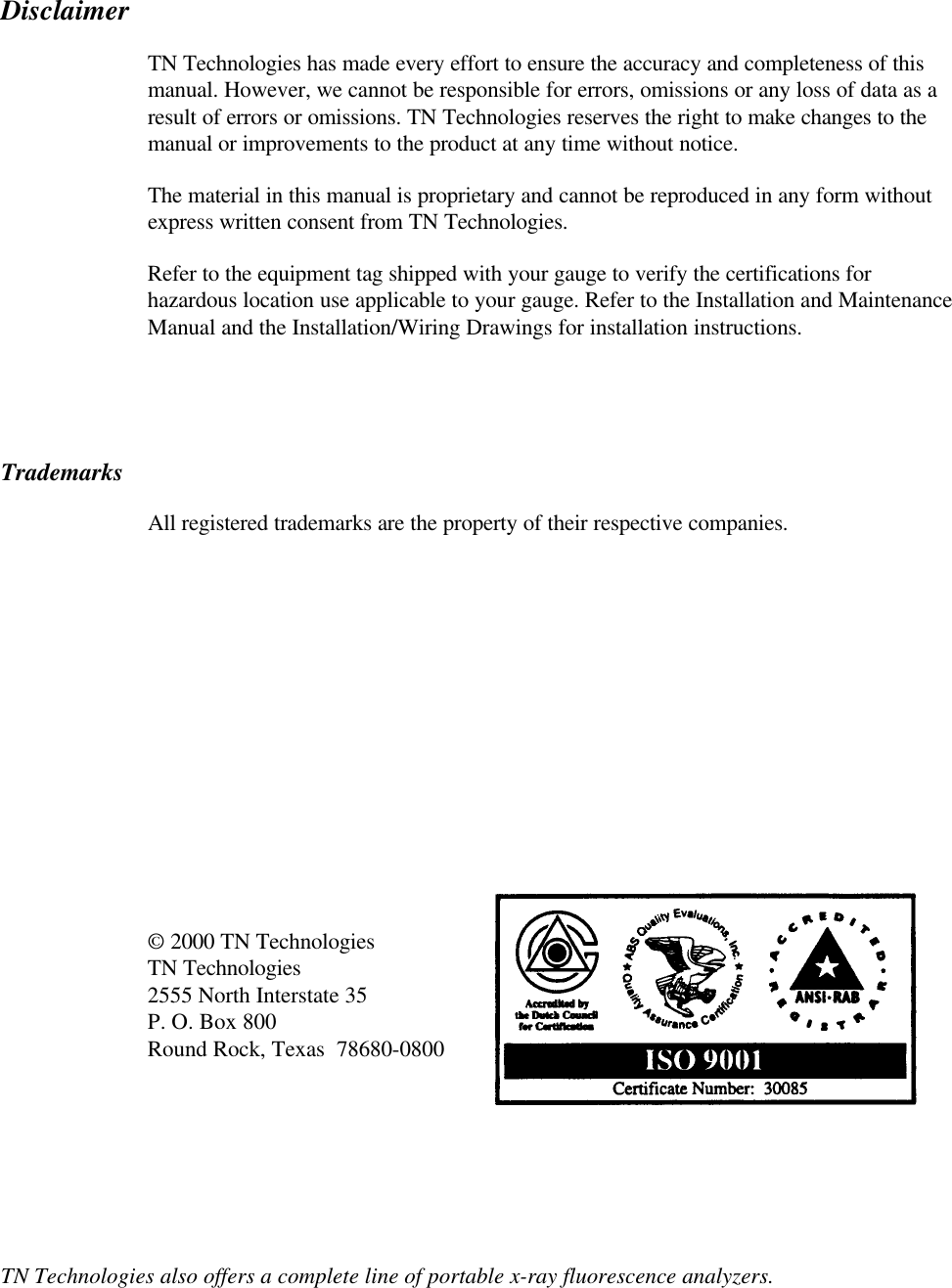
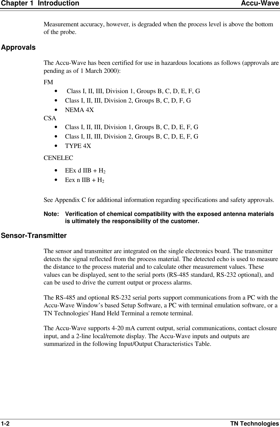
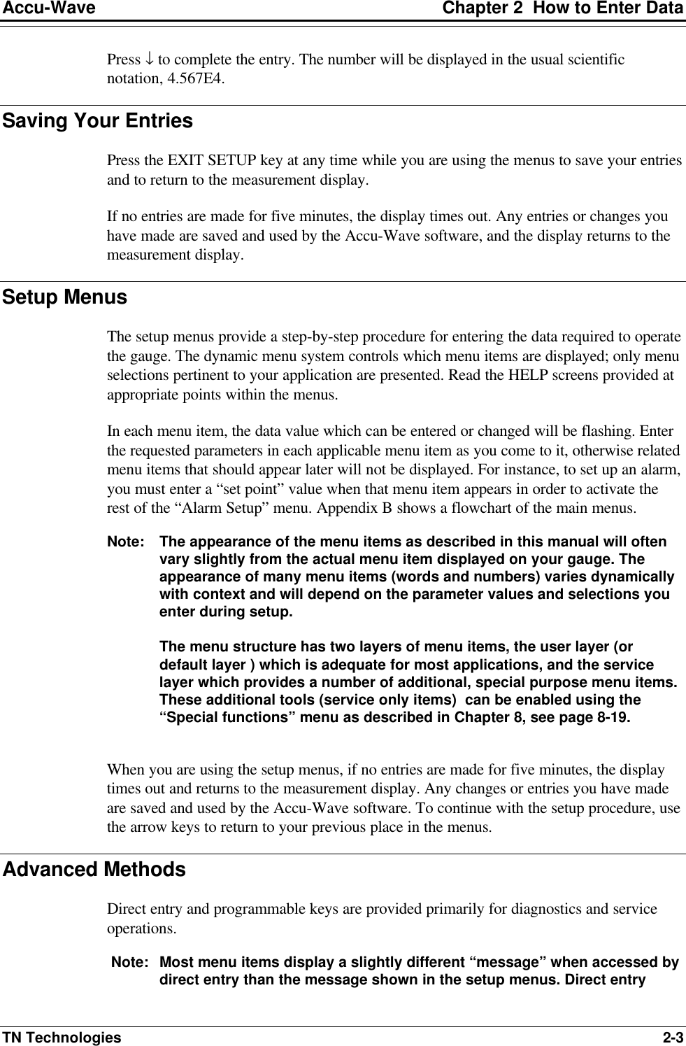
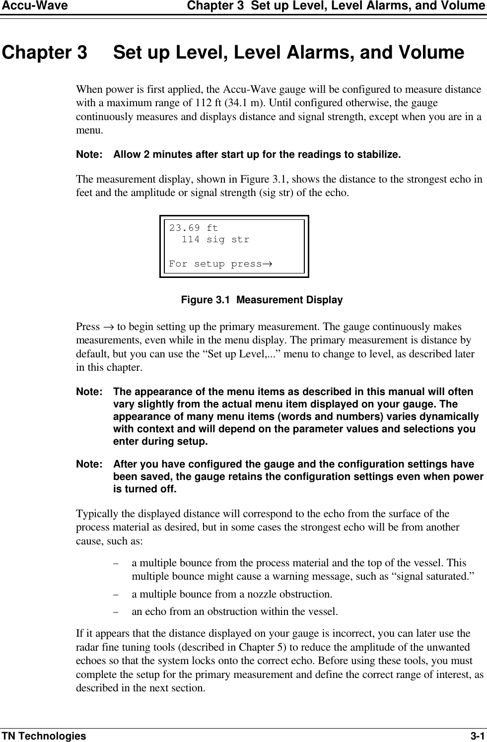
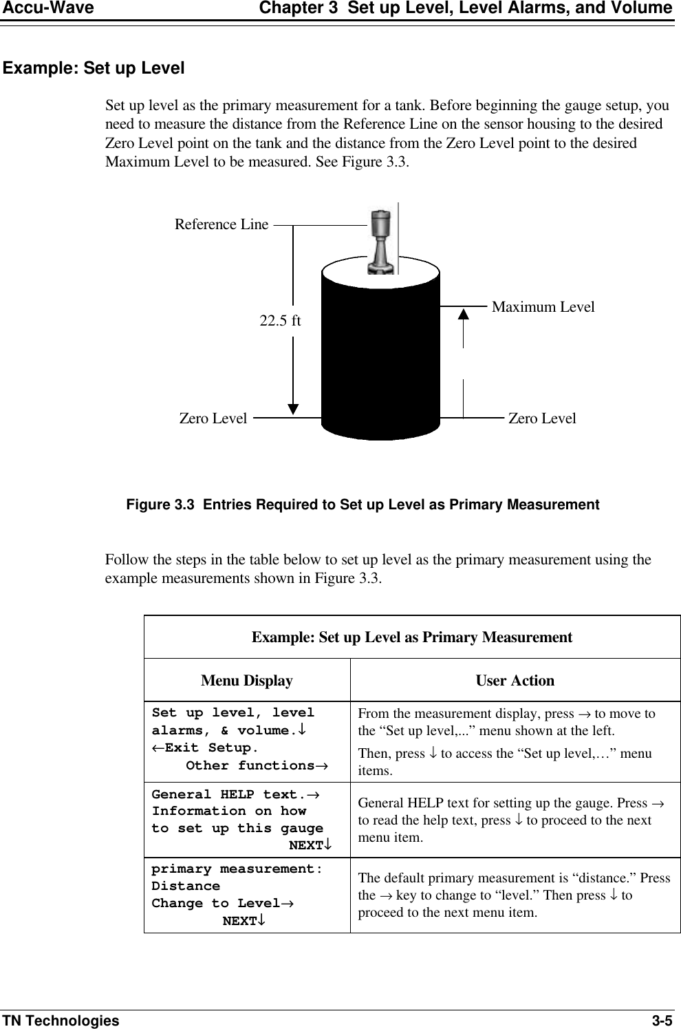
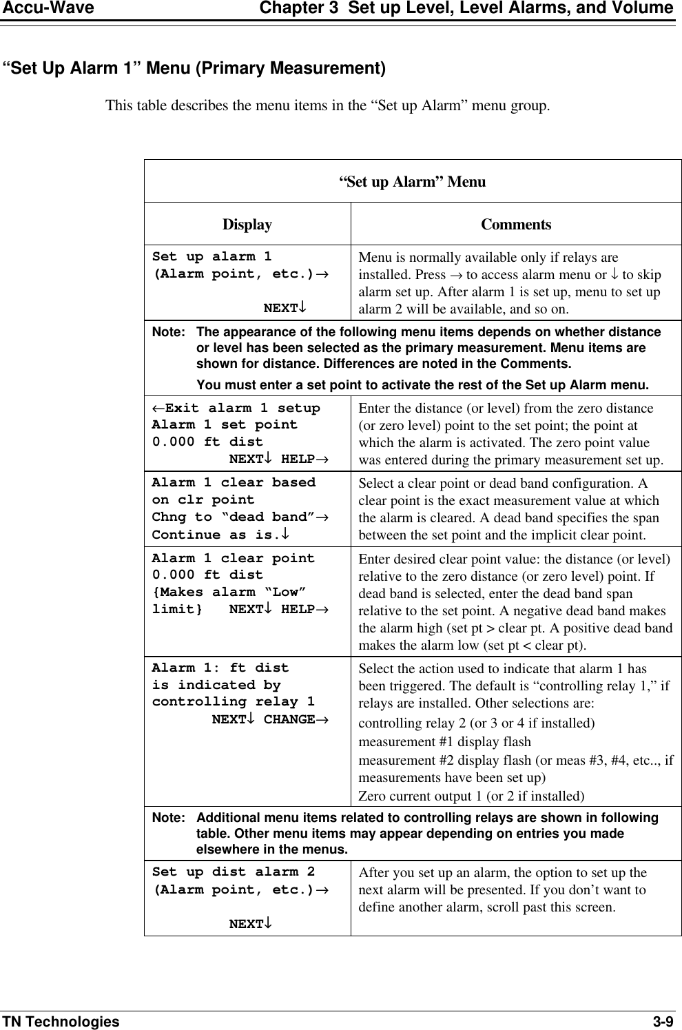

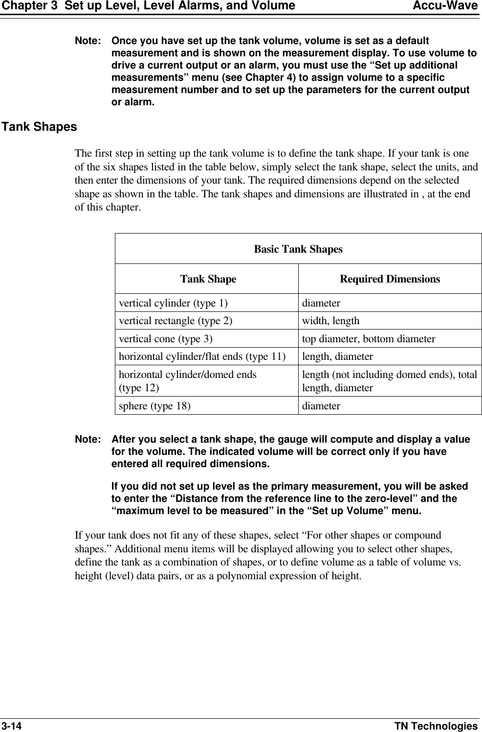
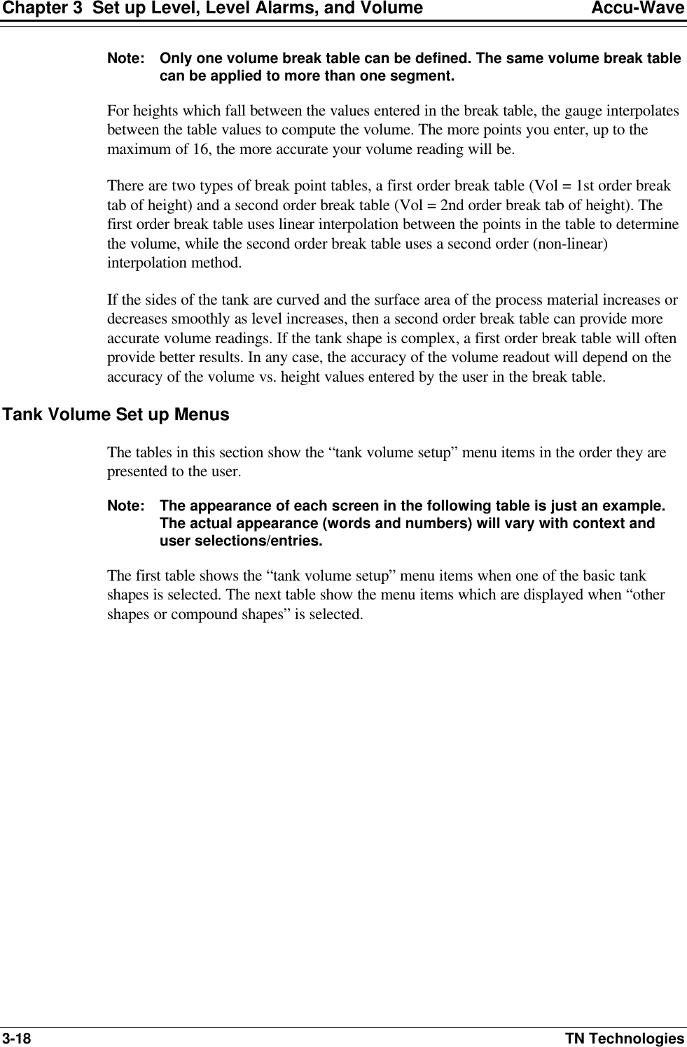

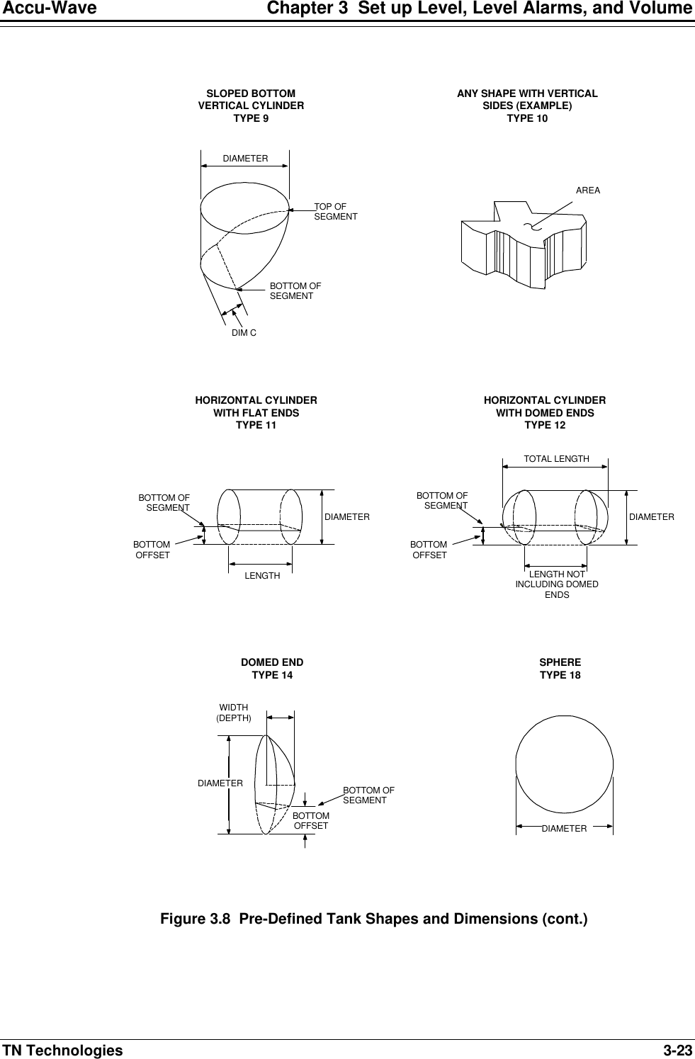
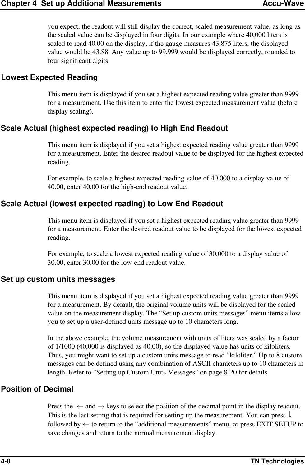
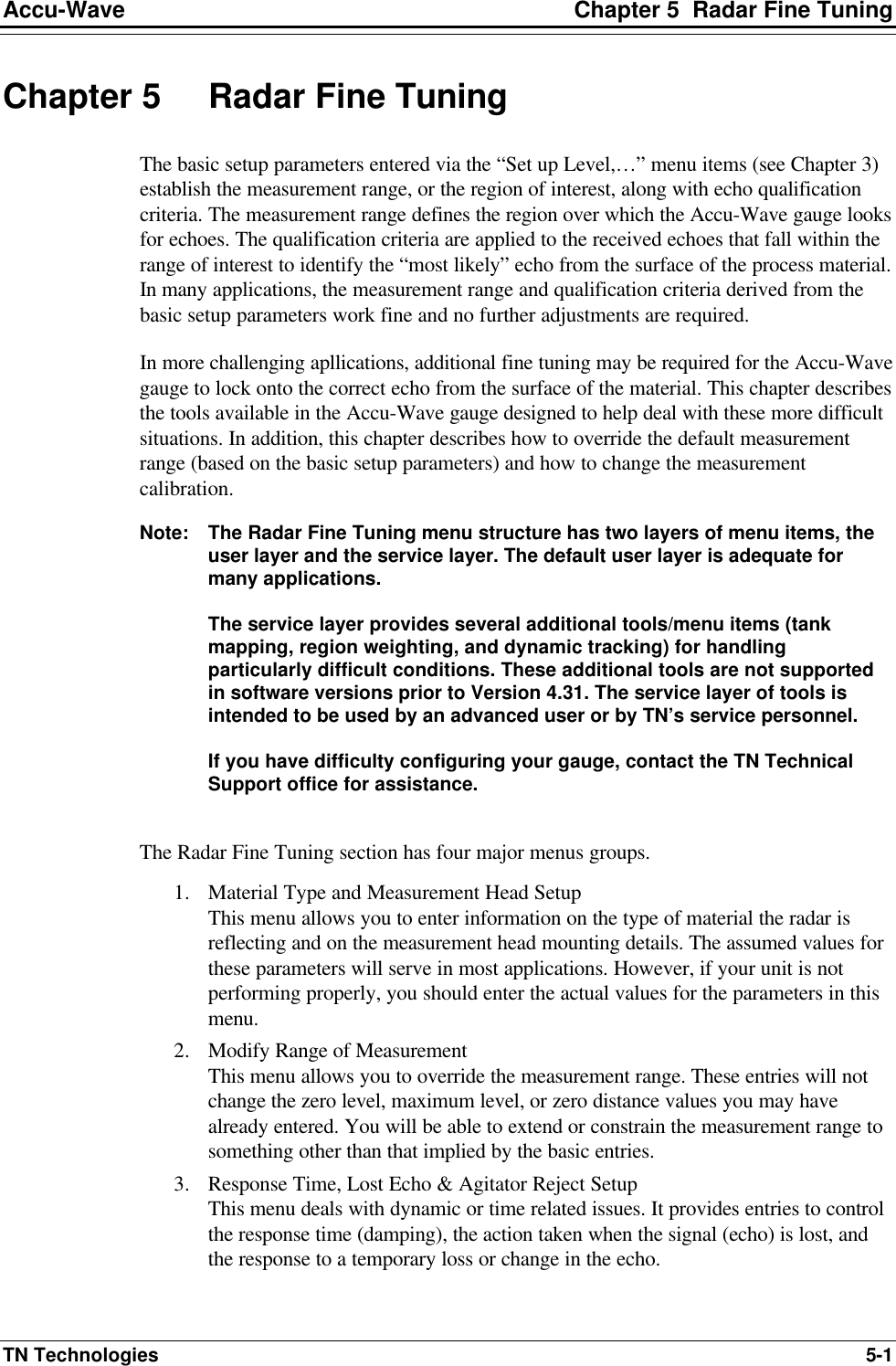
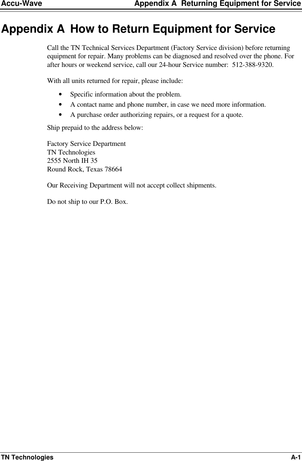
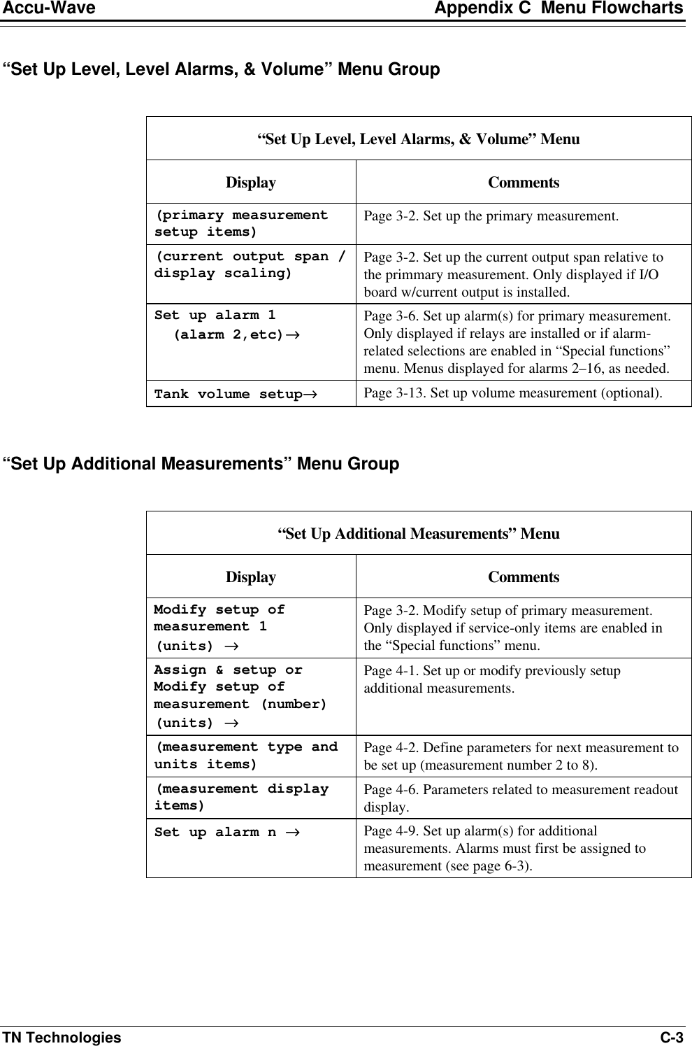
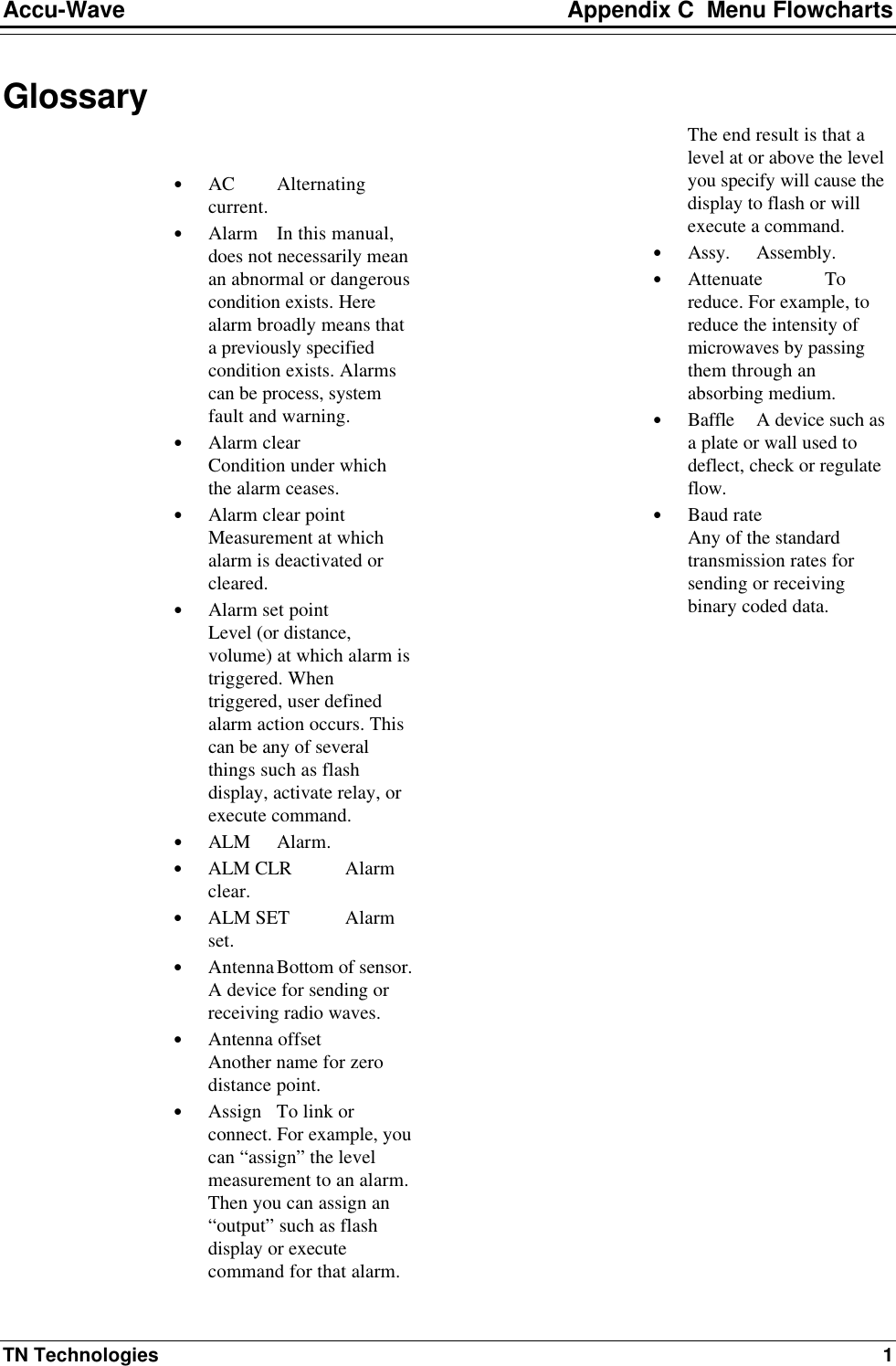
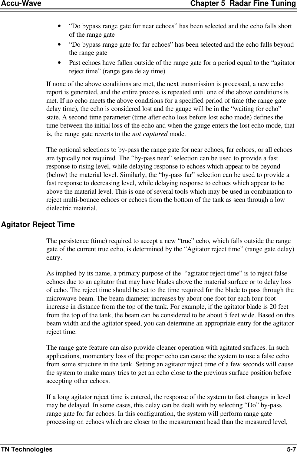
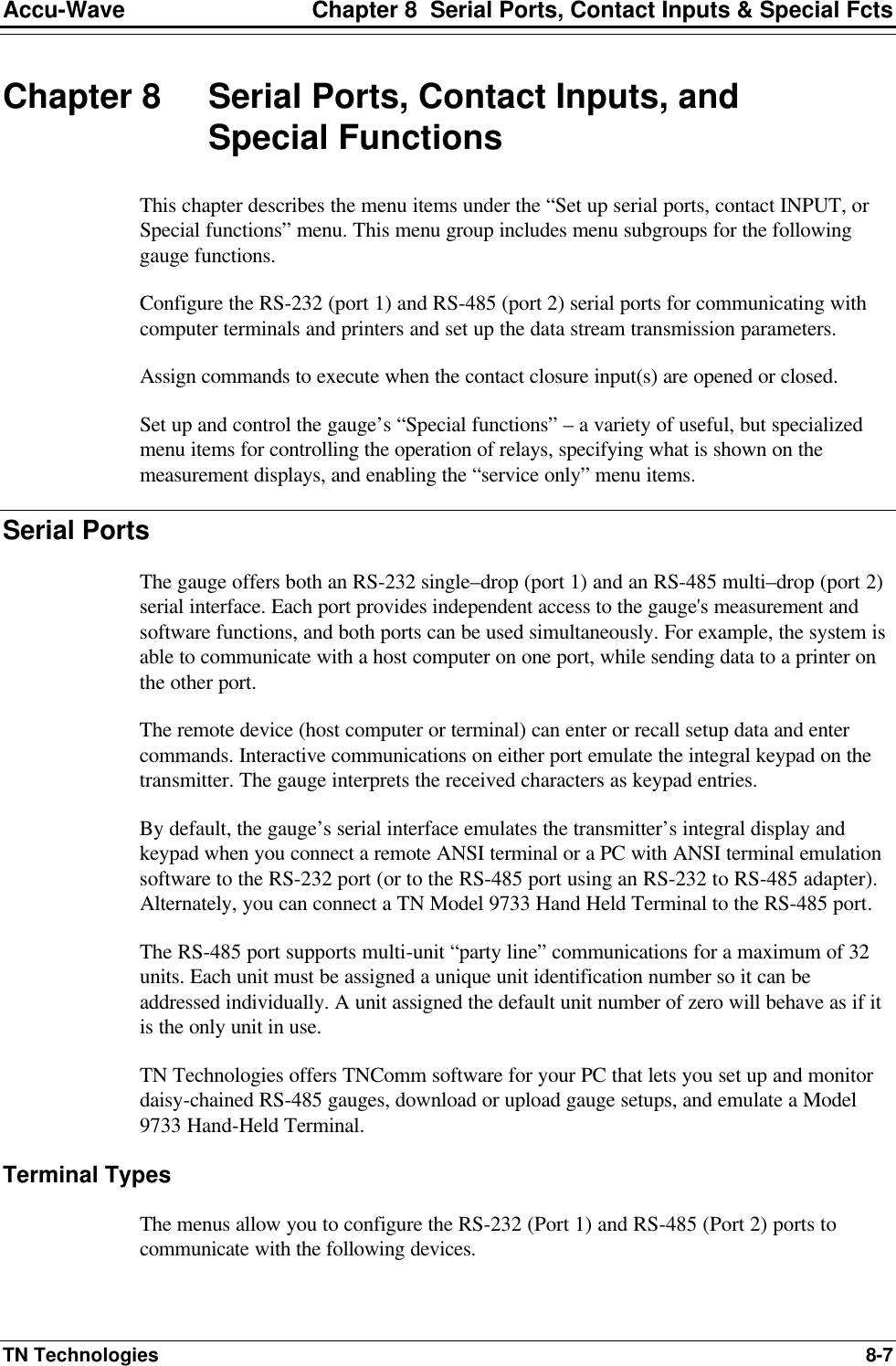
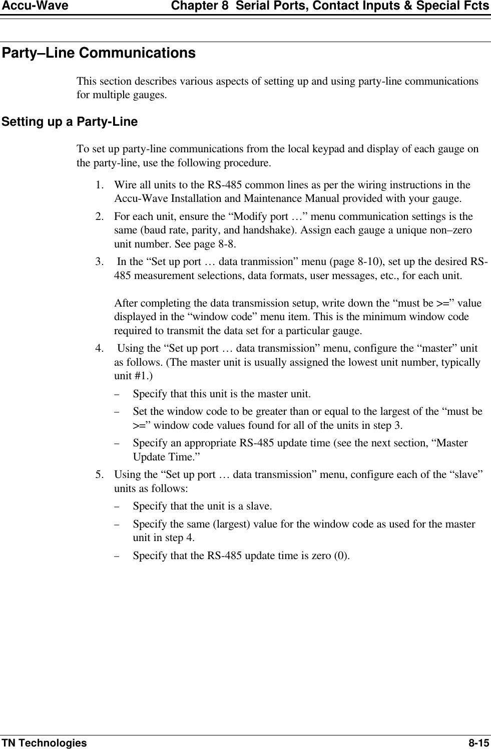
![Accu-Wave Chapter 5 Radar Fine Tuning TN Technologies 5-3 “Material Type and Measurement Head Setup” Menu Display Comments material type and measurement head setup→→ NEXT↓↓ Menu entry point for the “Material Type and Measurement Head Setup” menu group. Press → to access these menu items, press ↓ to continue to the next “Radar fine tuning” menu group. ←←Exit from: material type and measurement head setup→→ NEXT↓↓ Press ← to exit this menu group or press ↓ to proceed. Set gain = 0.000 (1.0 - 40, overrides automatic value) {2.711 in use} NEXT↓↓ [Service only item] If this variable is set to zero (default), the gauge will adjust the voltage gain of the I.F. (audio) signal automatically based on the ROI, and dielectric constant of the process material. If it is set to a non-zero value, this value is used to override the calculated gain setting. Direct Entry Code: ‘029003’ Material in tank is water based Change to “is not”→→ NEXT↓↓ This entry selects one of two default (assumed) values for the dielectric constant of the process material, which in turn sets the initial gain for the microwave signal. In most applications, selecting “water based” or “not water based” is adequate to set the gain. If you know the dielectric constant for your process material, you can enter it in the next menu item. Note: If your application involves more than one process material with different dielectric constants, enter the highest dielectric constant. Direct Entry Code: ‘025010’ Dielectric constant of process 0.000 (presently 80.00) NEXT↓↓ The “presently” assumed value is used for the dielectric constant of the process material unless you enter a non-zero value here. The assumed value is 80.00 if you selected “is water based” in the previous menu item, or 4.704 if you selected “is not water based.” Direct Entry Code: ‘028003’ measurement geometry 4 in antenna without flange mounted seal NEXT↓↓ CHANGE→→ Select “antenna without flange mounted seal” for an intrusive sensor mounting configuration or change to “antenna with flange mounted seal” for the isolation sensor configuration. Direct Entry Code: ‘005002’](https://usermanual.wiki/Thermo-MeasureTech/1440-15.Operating-Manual-for-1440/User-Guide-91777-Page-59.png)
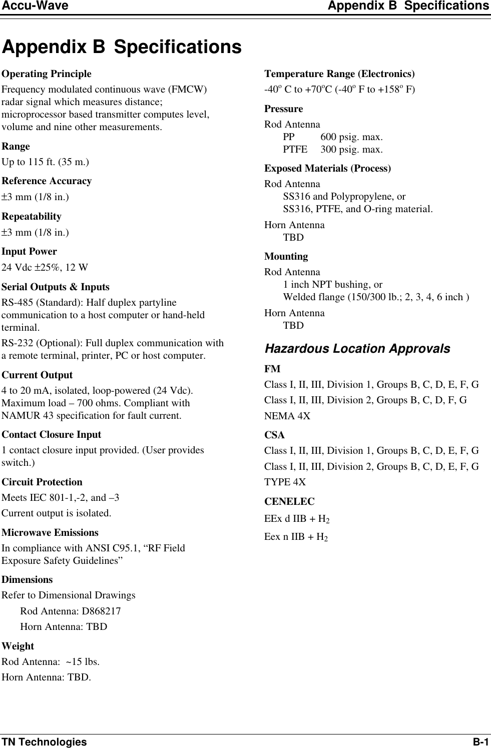
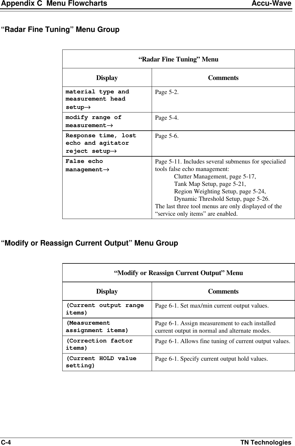
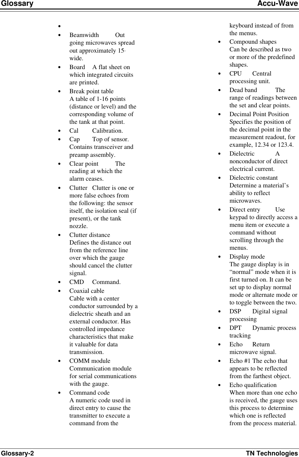
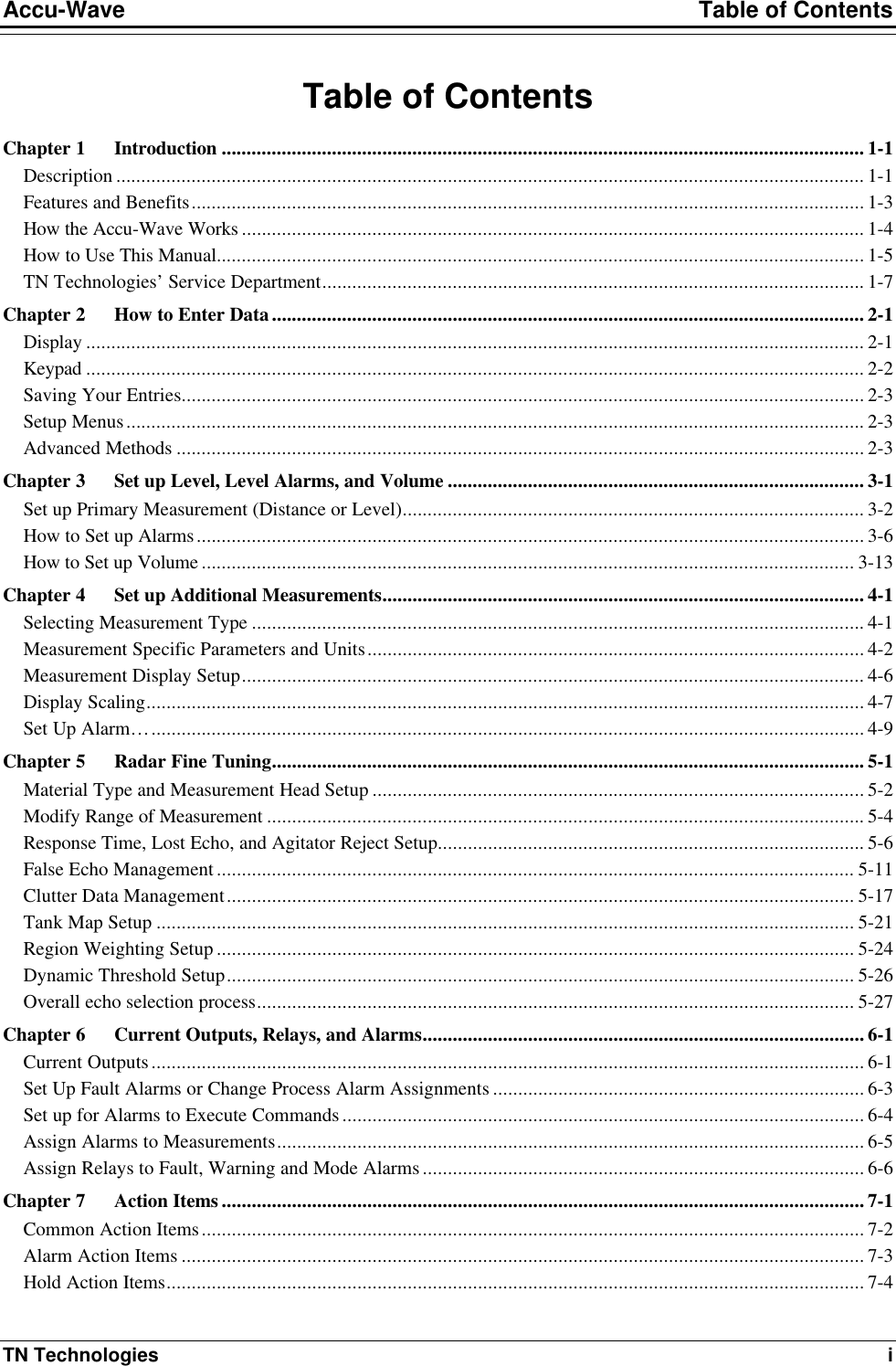
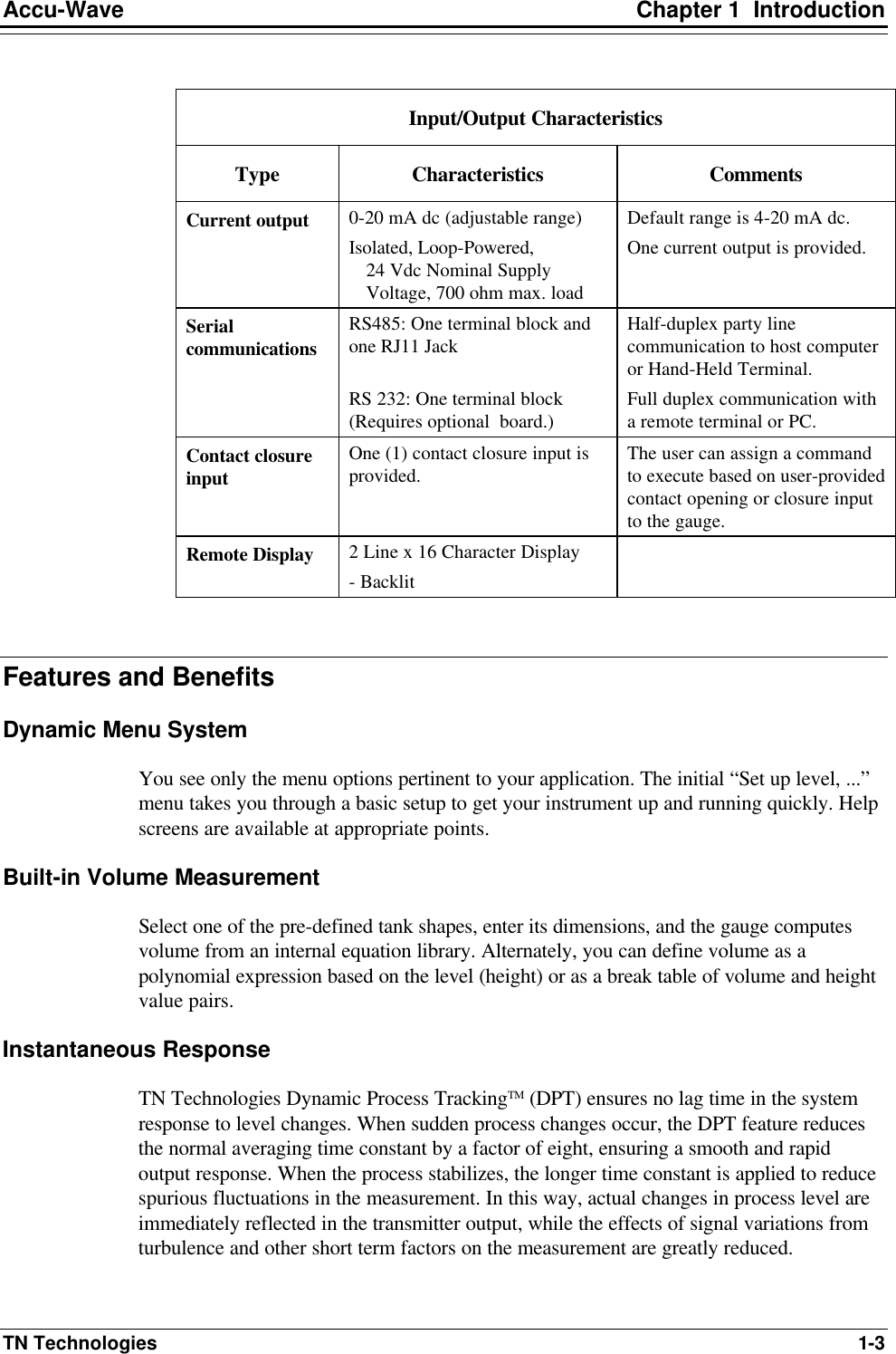
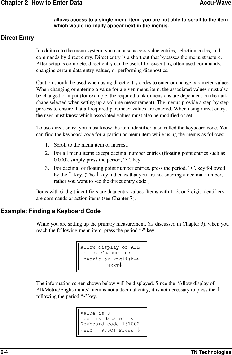
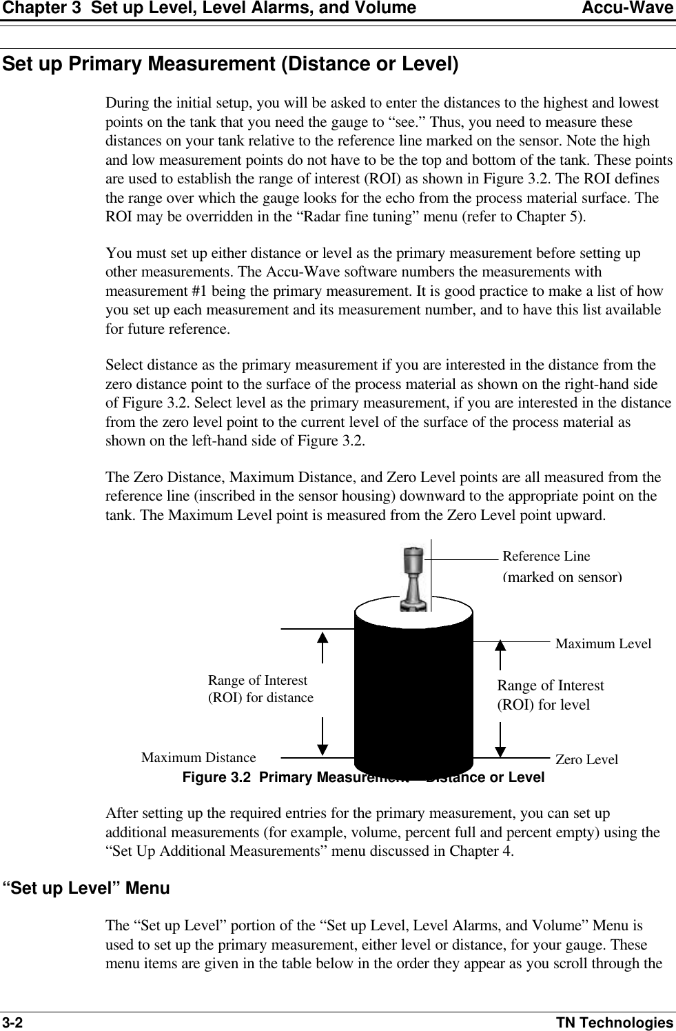
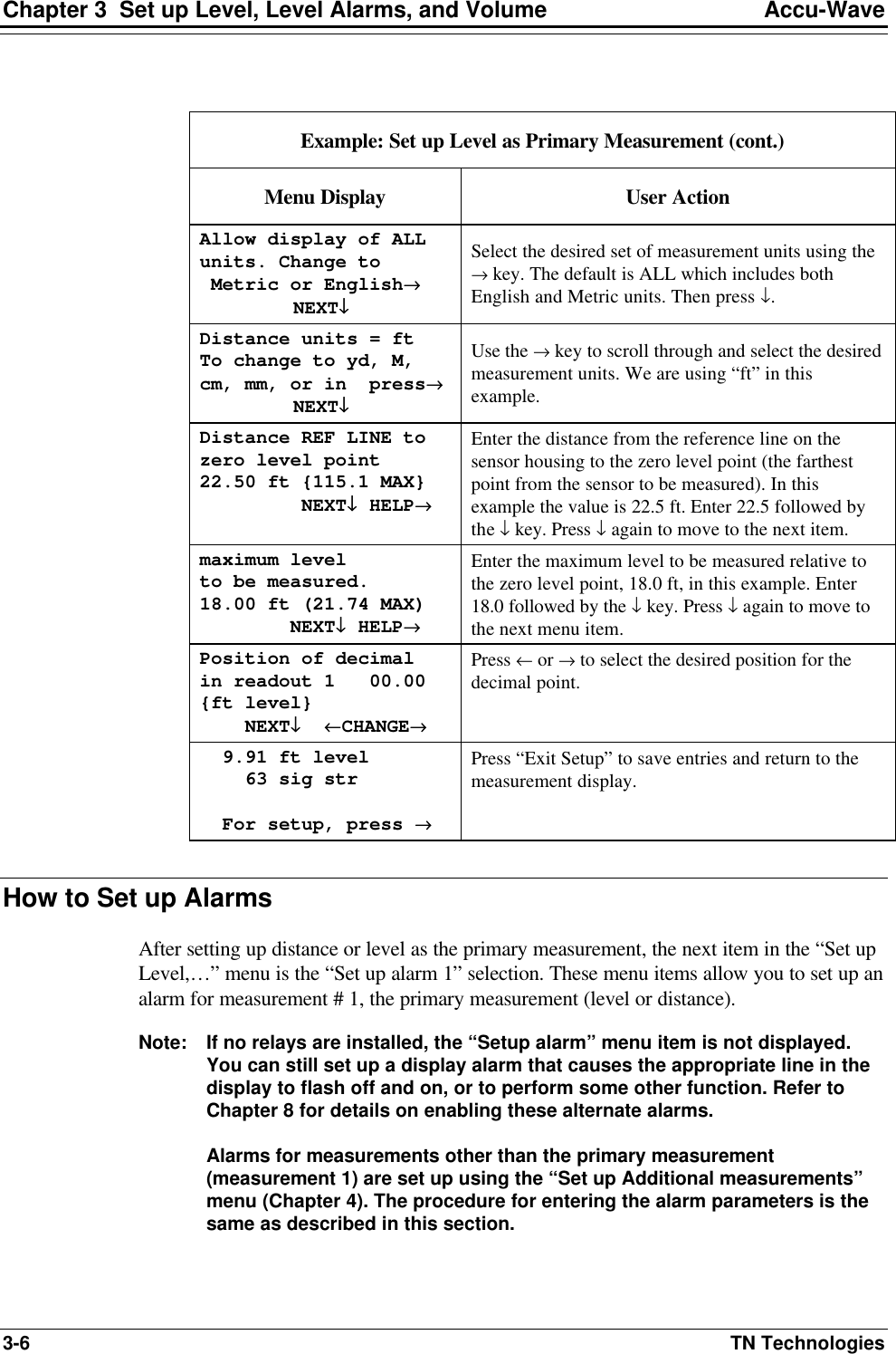
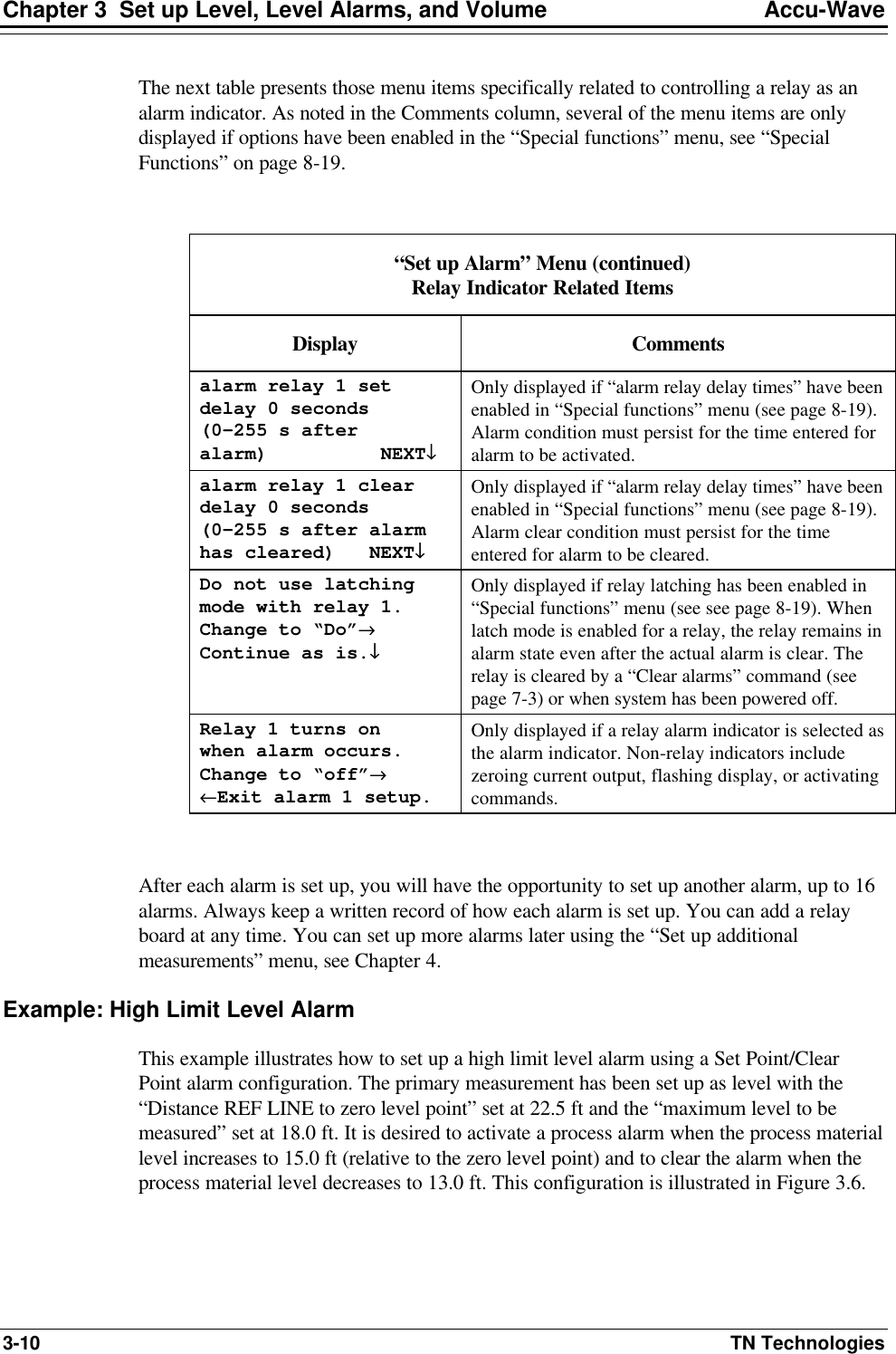
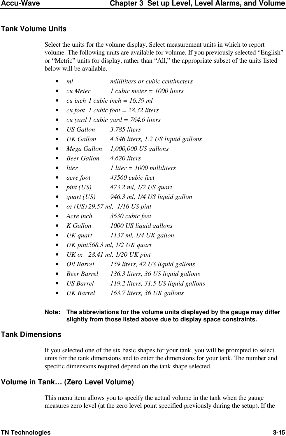
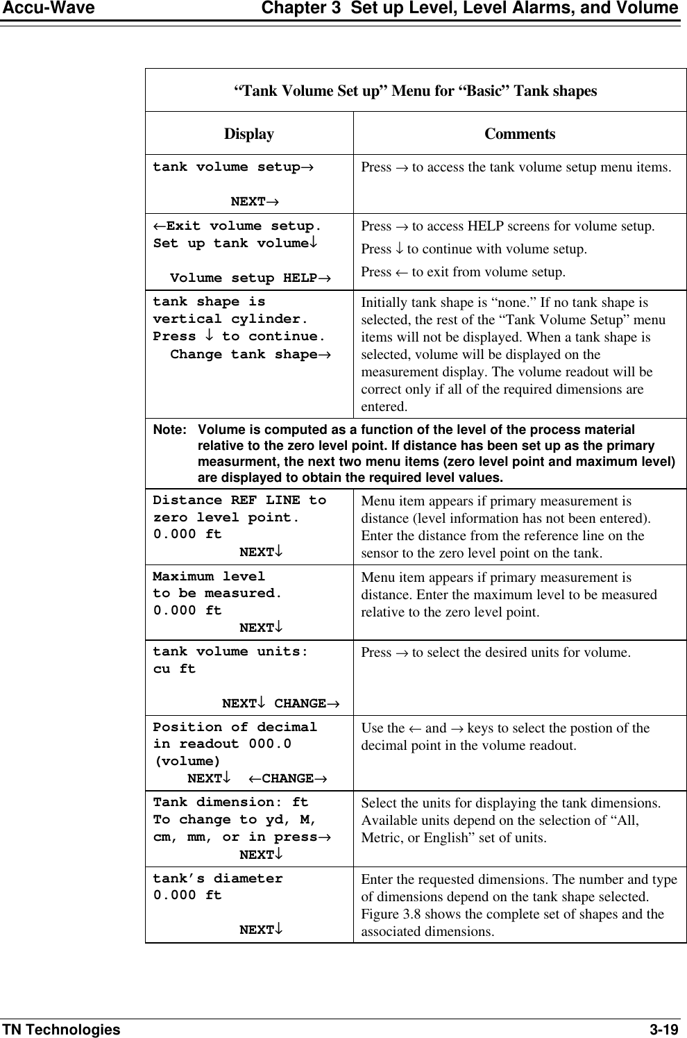
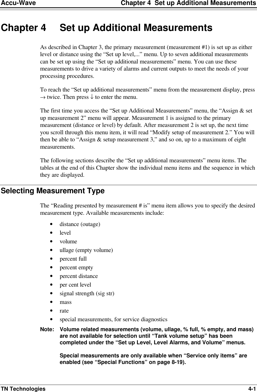
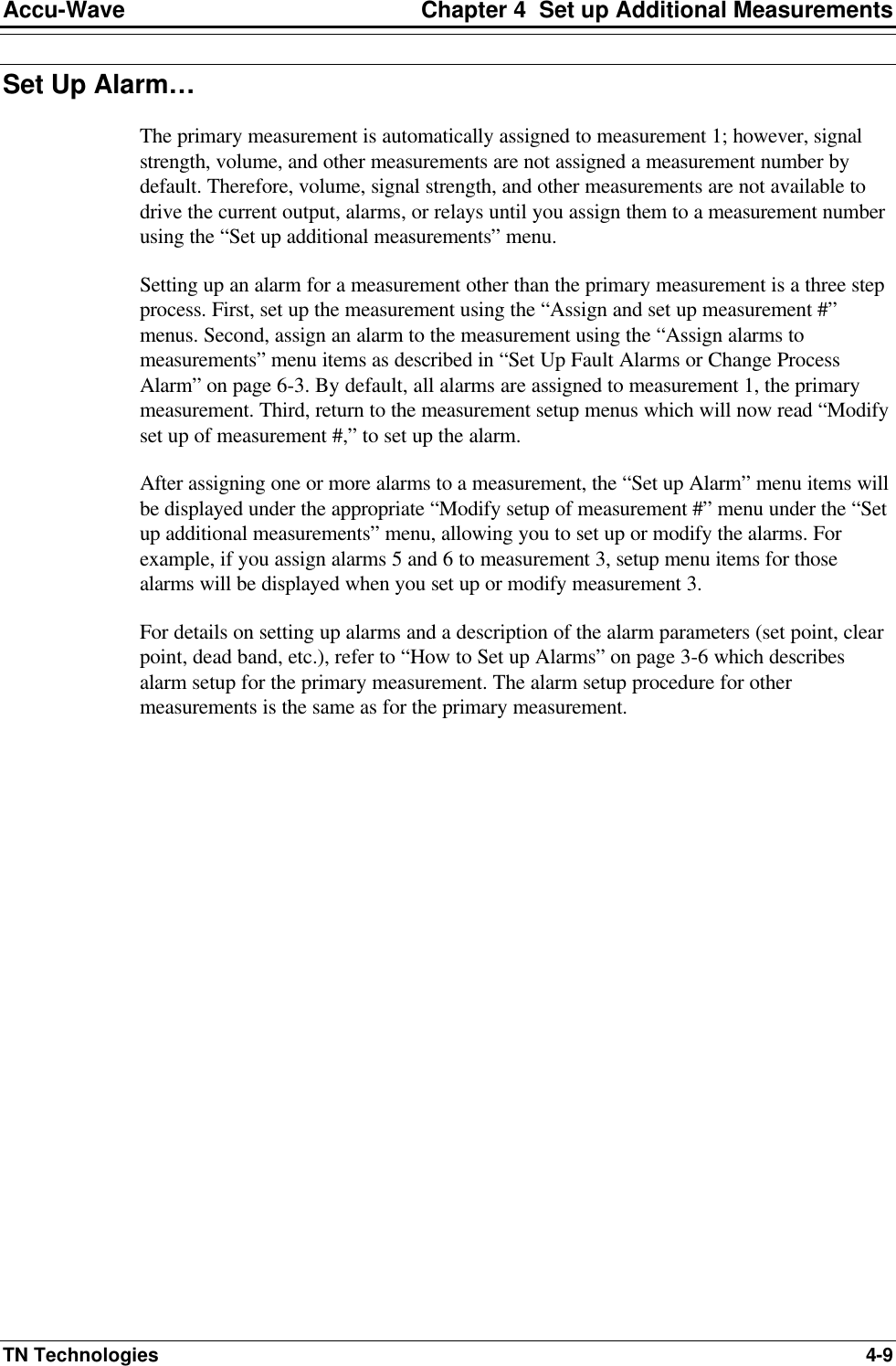
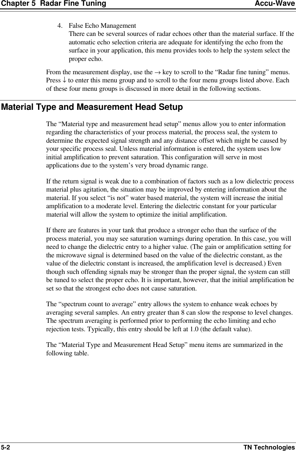
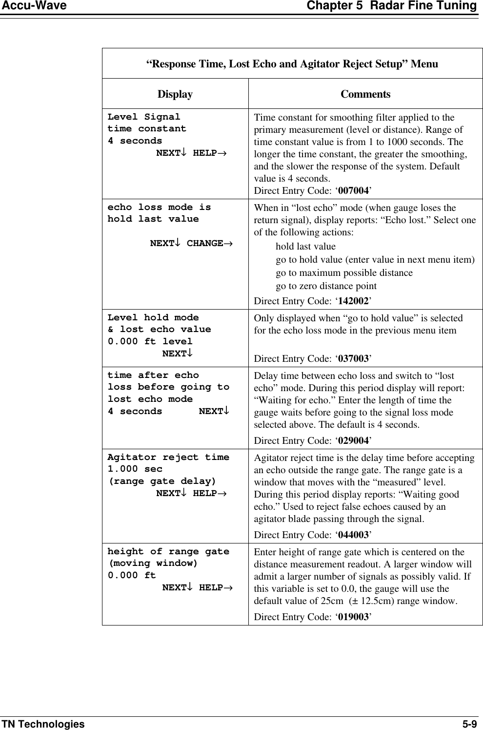
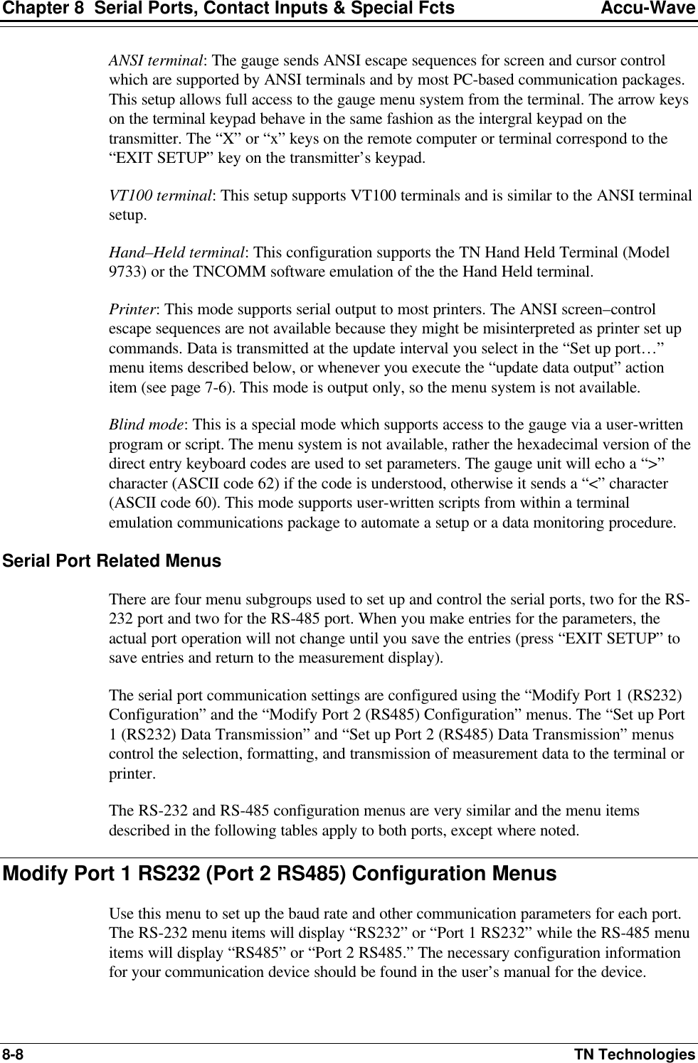
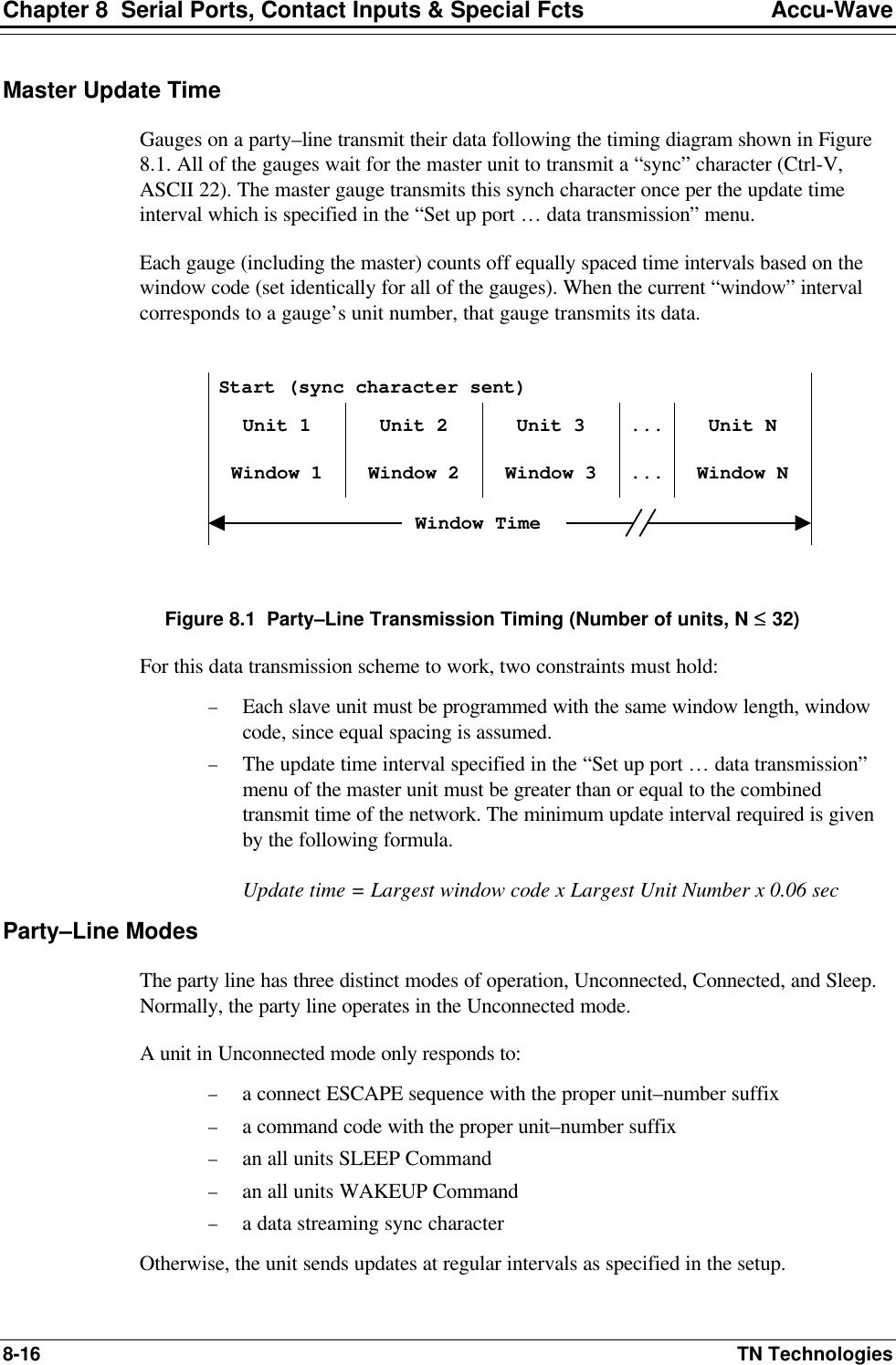
![Chapter 5 Radar Fine Tuning Accu-Wave 5-4 TN Technologies “Material Type and Measurement Head Setup” Menu (continued) Display Comments flange mounted seal velocity correction value = 0.000 NEXT↓↓ HELP→→ Displayed if “antenna with flange mounted seal” is selected above. Enter velocity correction value (in cm) to correct for the reduced propagation velocity of the process seal(s). See Error! Reference source not found.. If this value is left at zero, the process seal will induce a small offset error. Direct Entry Code: ‘086003’ spectrum count to average 1 (1 - 64) NEXT↓↓ HELP→→ Increase number of averages to improve measurement on non-agitated low dielectric materials such as light hydrocarbons. Values over 8 can slow the response of the gauge. Do not use values > 1 on agitated to turbulent surfaces. Direct Entry Code: ‘022004’ Optimize system for best Accuracy Chg to “Resolution”→→ Continue as is.↓↓ [Service only item] Use default value for best accuracy. Changing to “Resolution” can somewhat improve ability to resolve closely spaced echoes at the cost of a slight decrease in the accuracy of the distance/level measurement. Modify Range of Measurement To maximize resolution and minimize false echoes, the system establishes a Range of Interest (ROI) over which it looks at candidate echoes. The default ROI is based on values entered during the primary measurement setup (see page 3-2). If the primary measurement is level, the ROI extends from the zero level point to the maximum level point. If distance is the primary measurement, the ROI extends from the zero distance point to the maximum distance point. Using the “Modify Range of Measurement” menu items, the ROI can be modified to allow measurements below the zero level (readout will show a negative level) or above the “maximum” level. Alternately, the ROI can be set to exclude the zero level point. The slope correction and distance offset correction entries allow you to fine tune the gauge’s distance measurement to correct for any variations due to the gauge installation or to adjust the gauge’s readout to match the distance / level readings from another level measuring device.](https://usermanual.wiki/Thermo-MeasureTech/1440-15.Operating-Manual-for-1440/User-Guide-91777-Page-60.png)
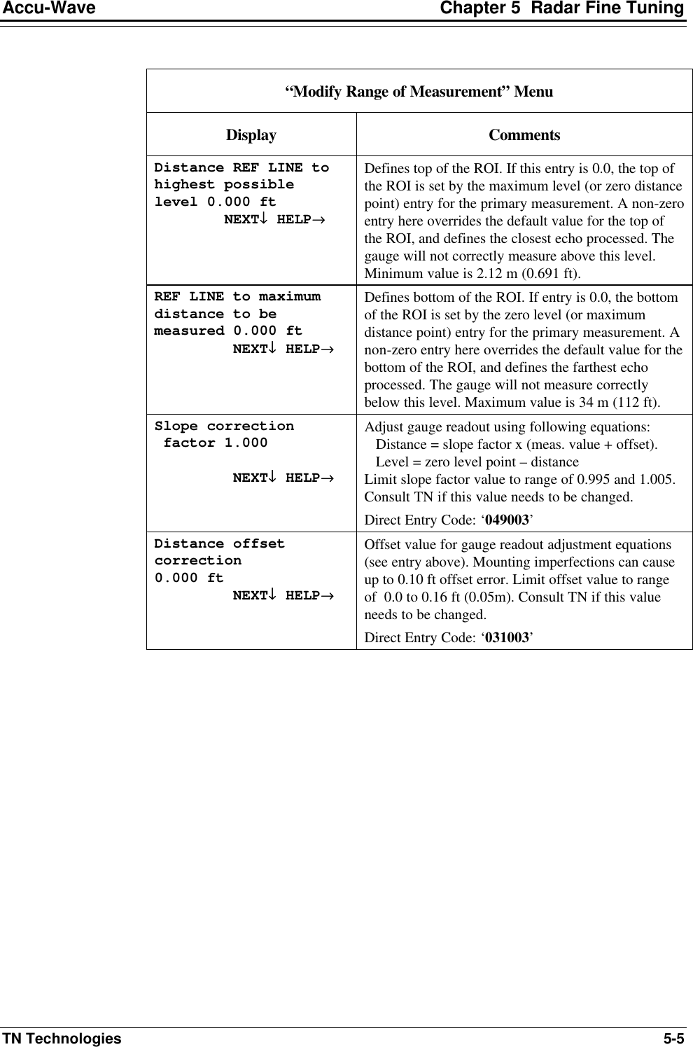
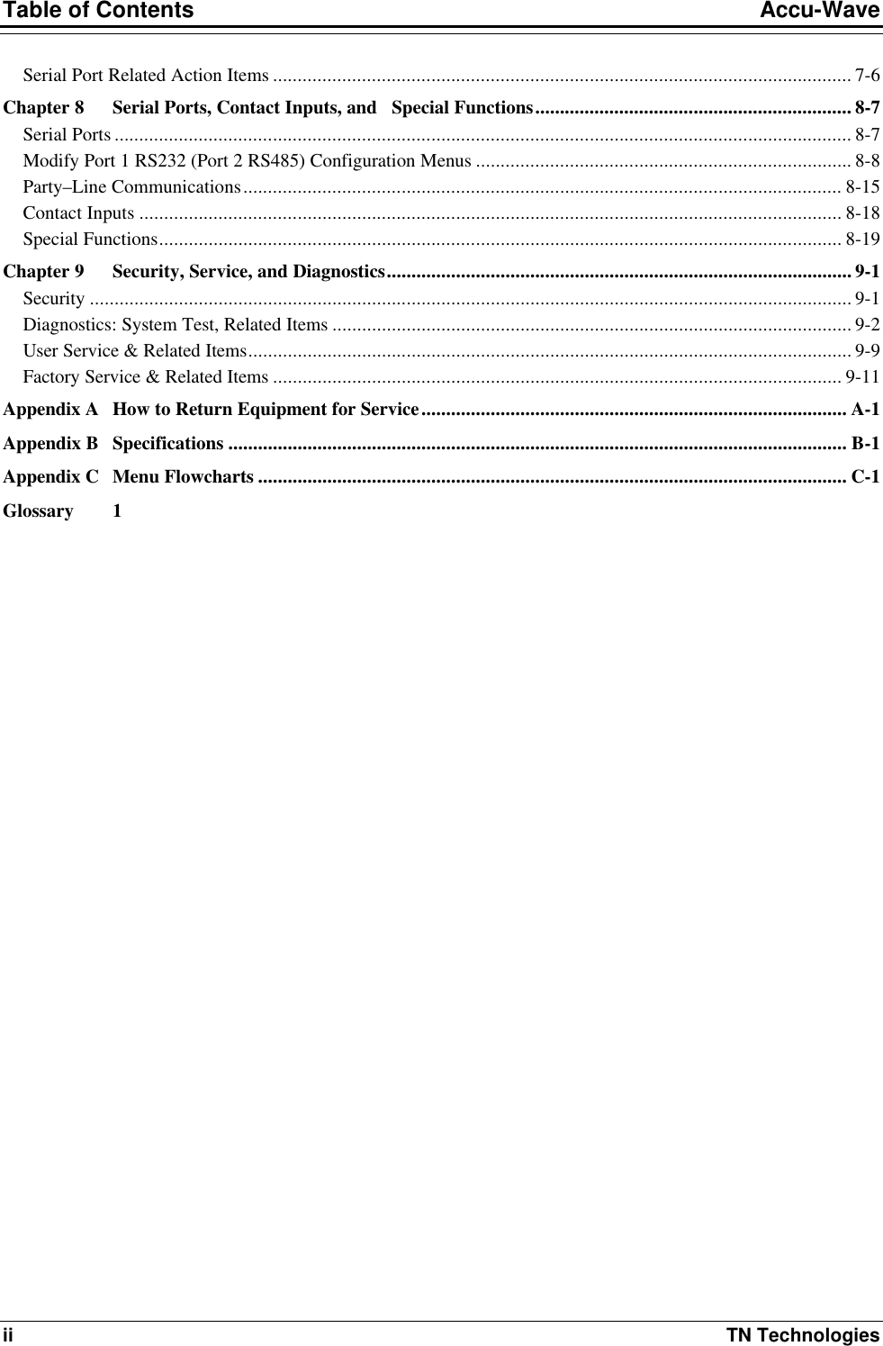
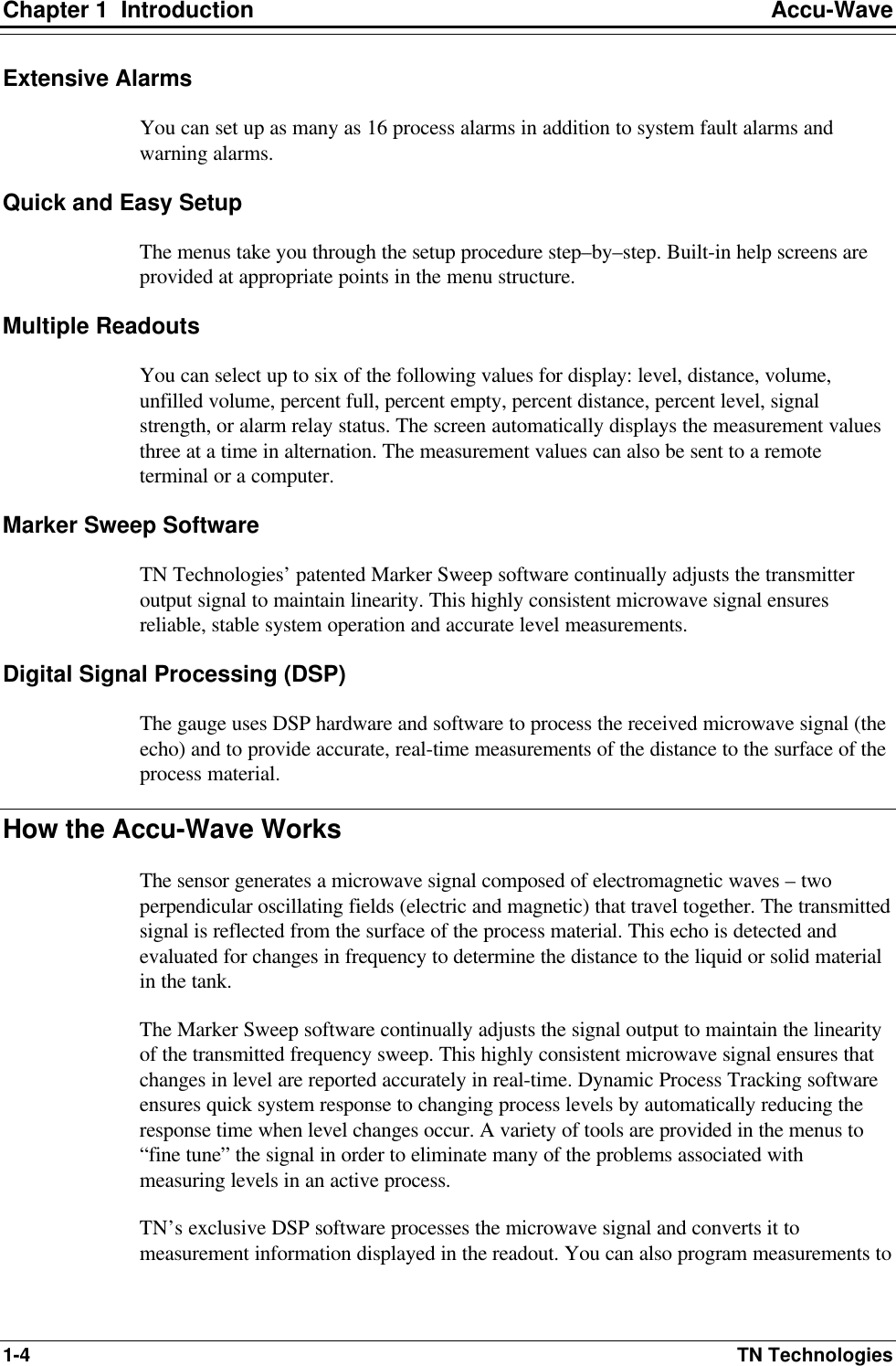
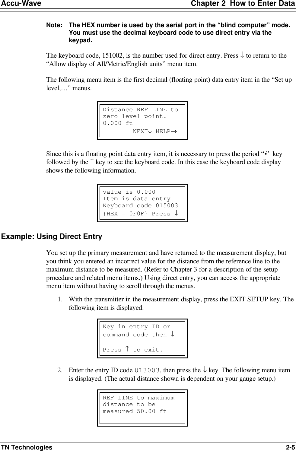
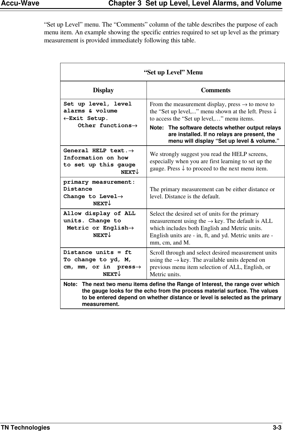
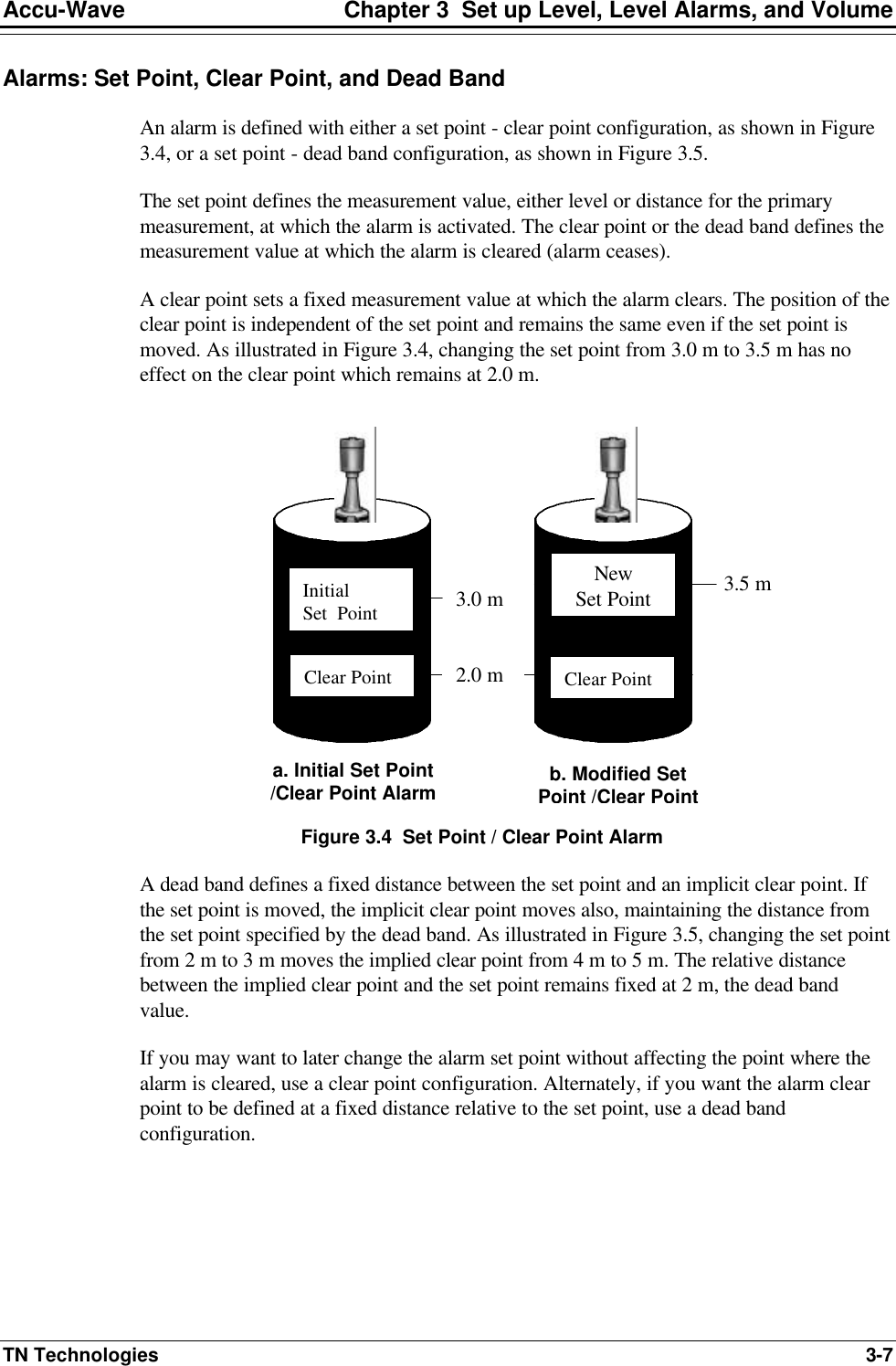
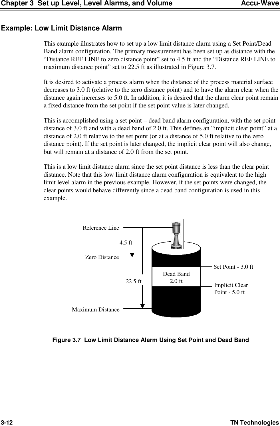
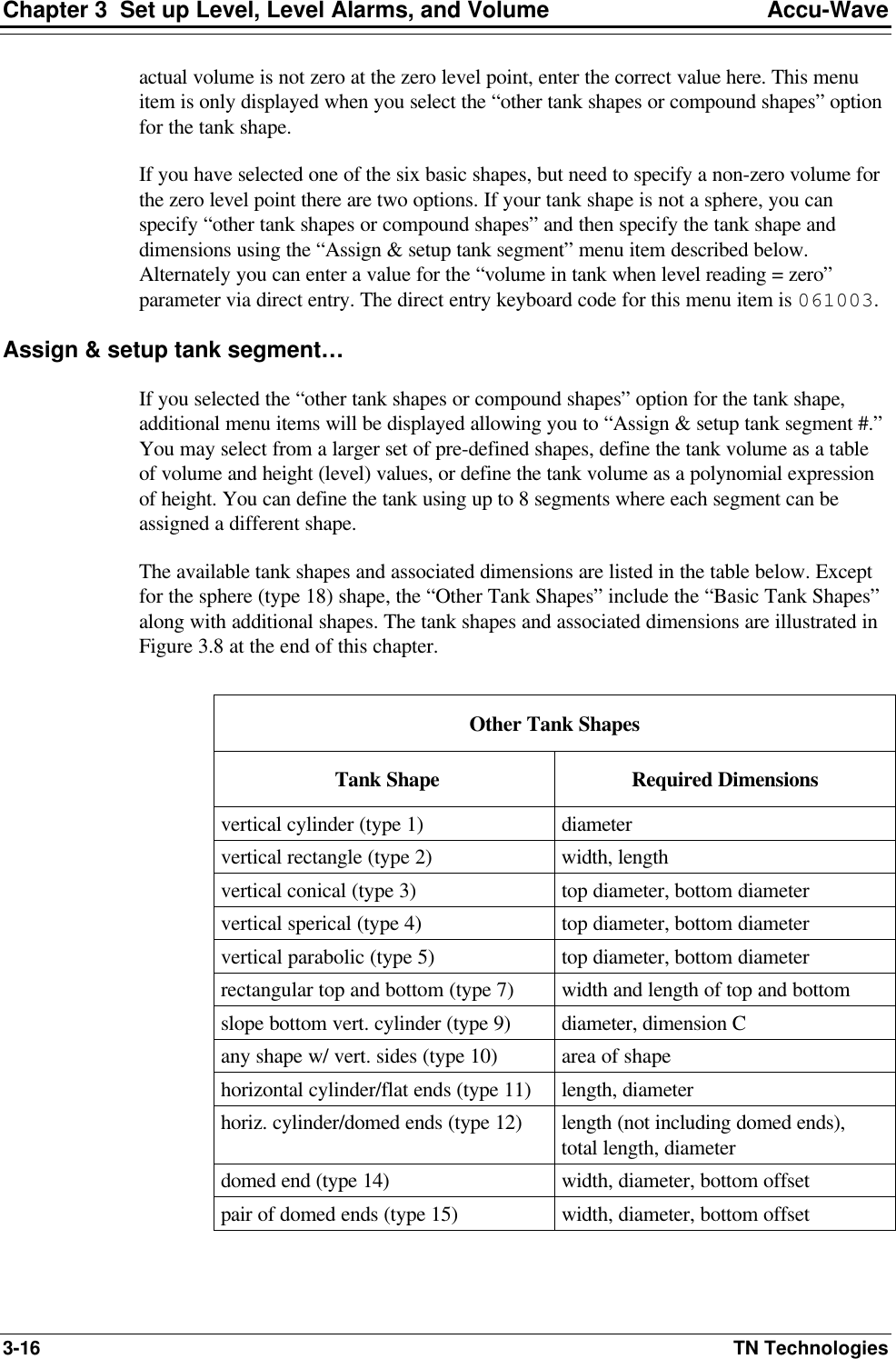
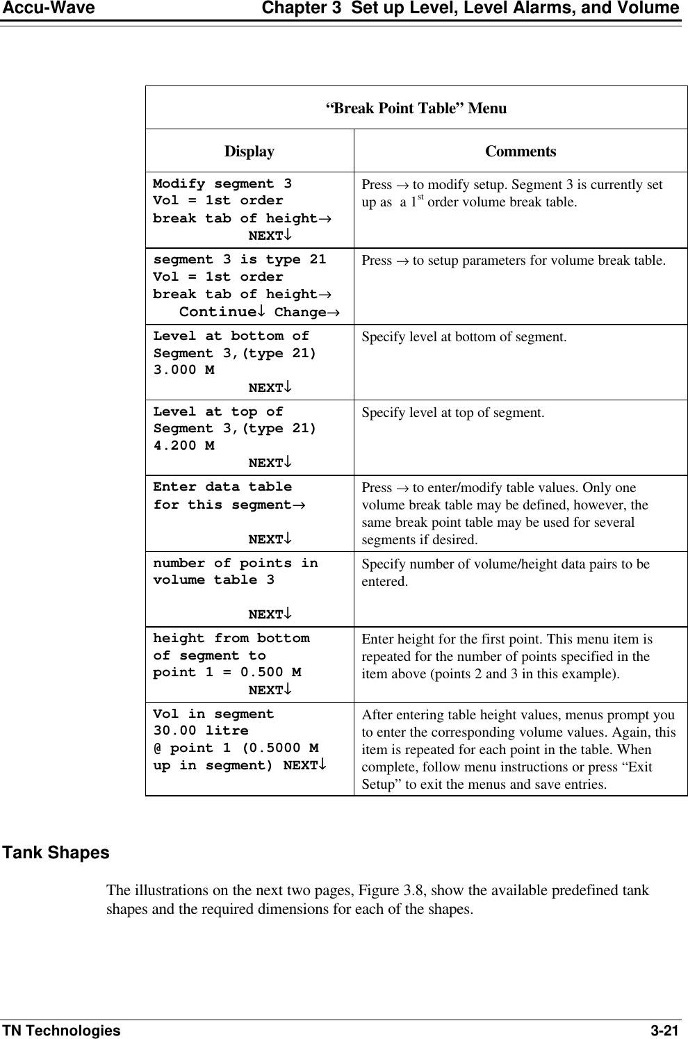
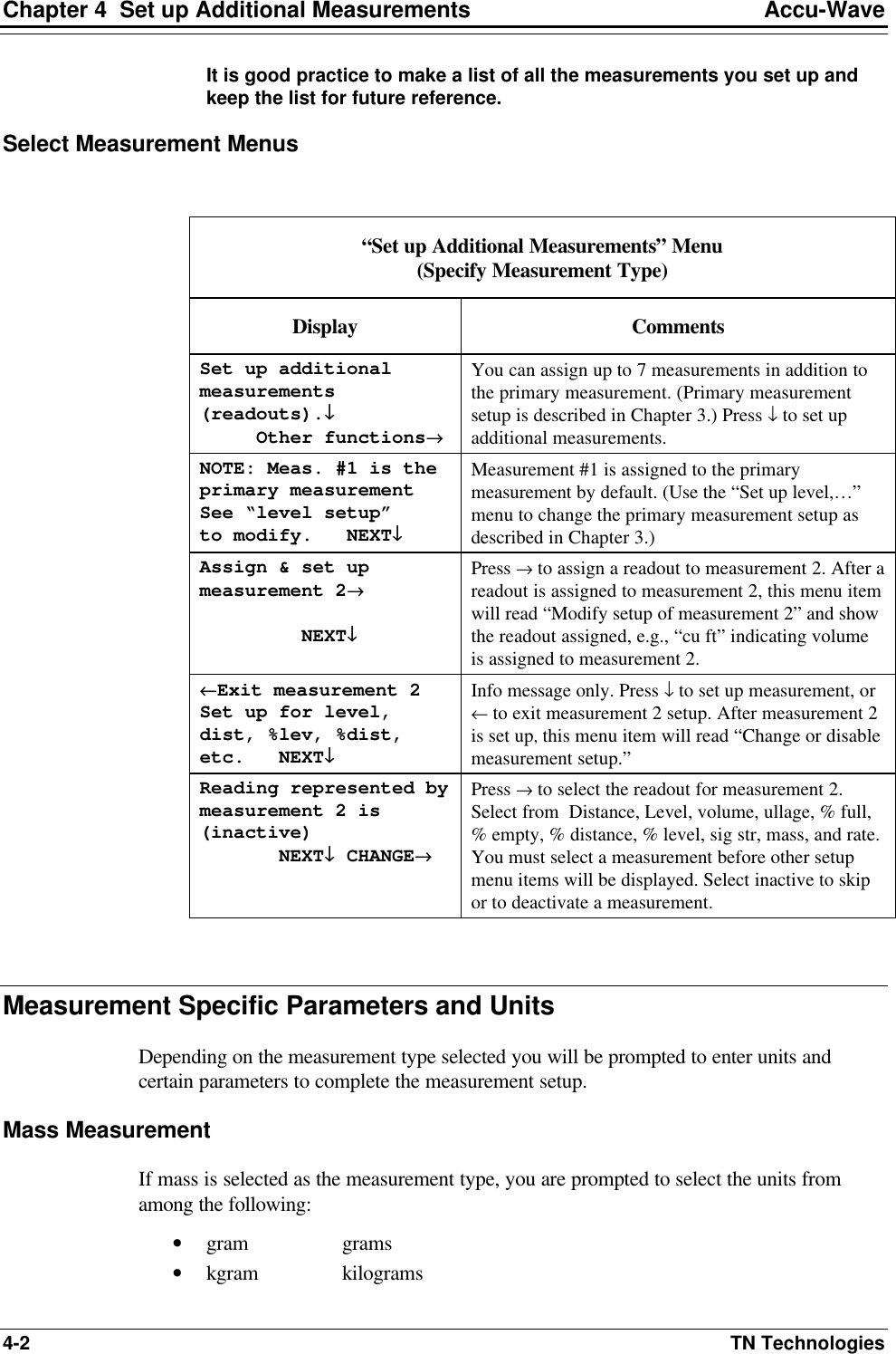
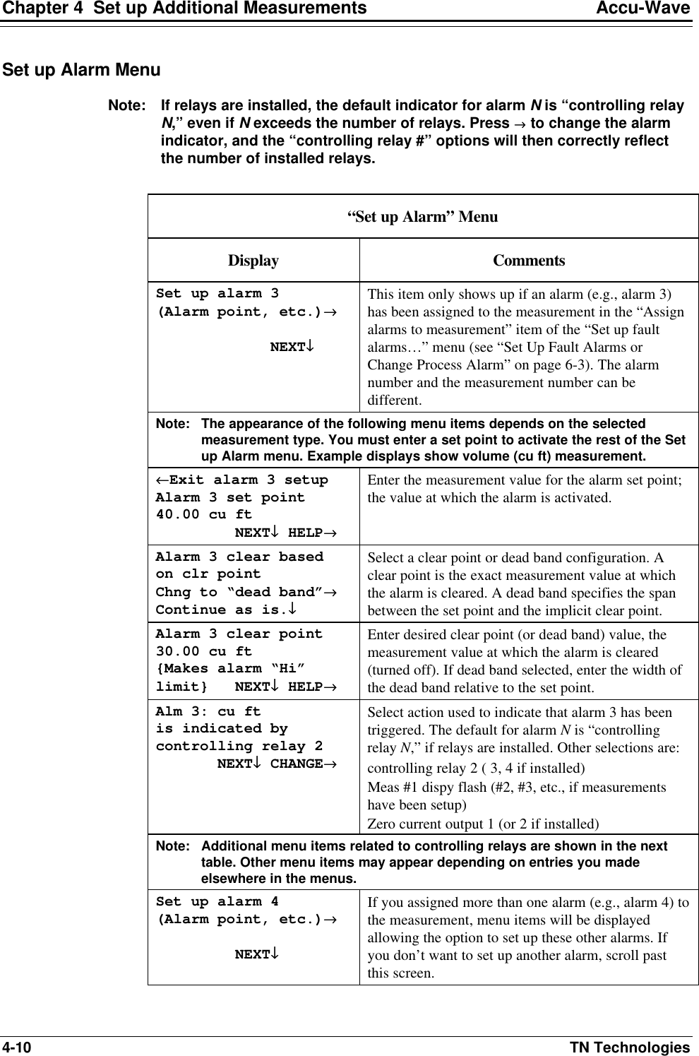
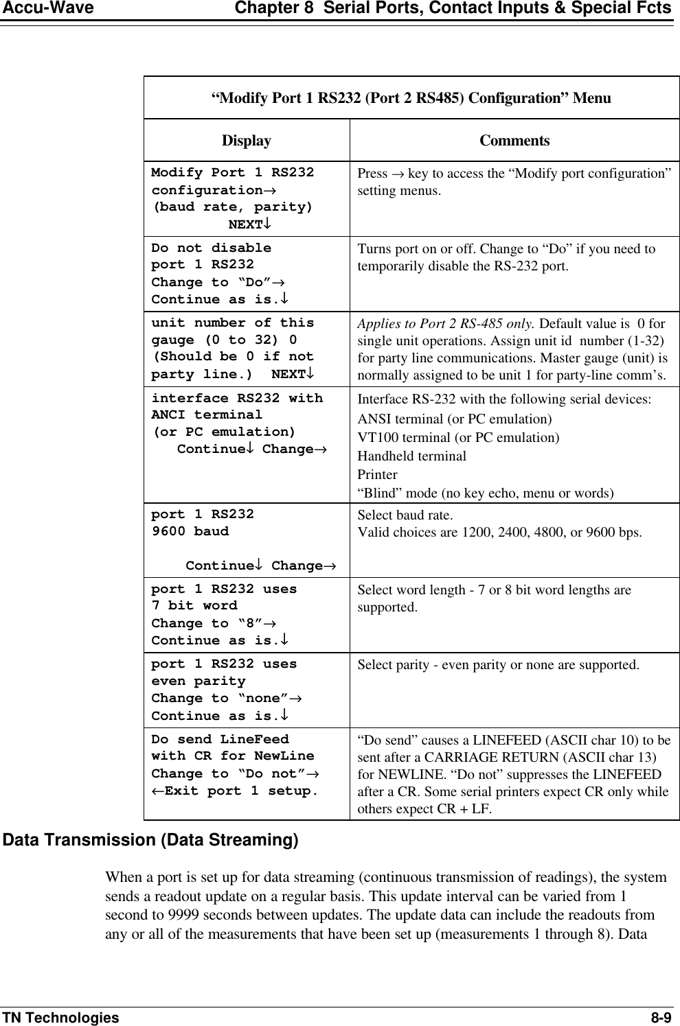
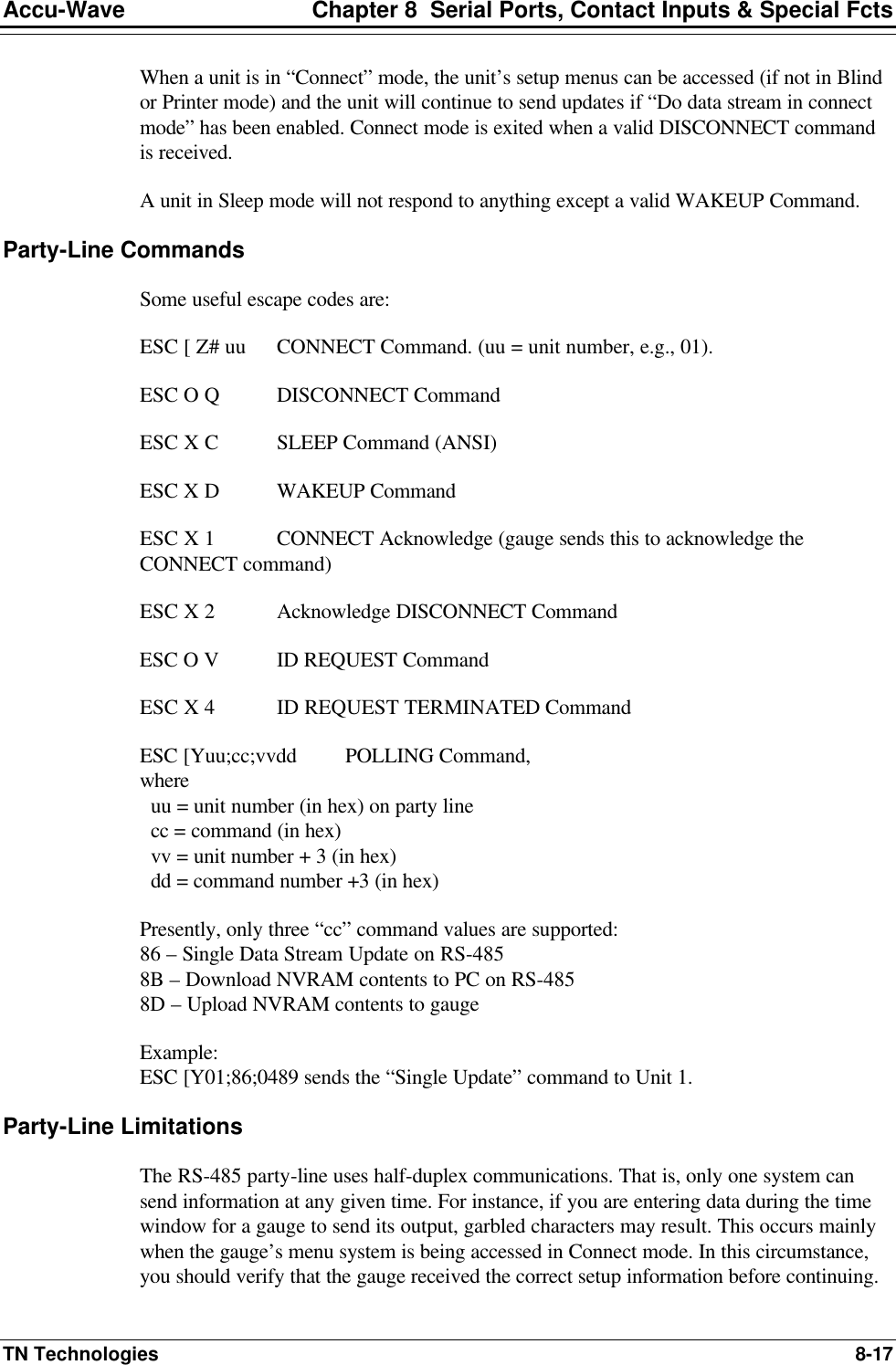
![Chapter 5 Radar Fine Tuning Accu-Wave 5-8 TN Technologies but will allow any echoes beyond the level (lower) to be accepted without considering the range gate. Note: If you want to use an agitator reject time entry of “forever,” enter 65535 seconds. Range Gate Weighting Factor (GWF) A range gate weighting factor (GWF) can be applied to echoes that fall within the range gate. A GWF value greater than 1 gives additional preference to echoes within the range gate during the processing to select the best candidate. A GWF value less than 1 reduces the preference given to echoes within the range gate. You may also affect the system response by changing the height (span) of the range gate. The default value for the range gate height is 25 cm (~10 in). Entering a larger value for the range gate height would increase the number of echoes considered valid and which could be used to update the current measurement values. Using a larger range gate height and a short time constant value would allow the range gate to move quickly as the actual material level moves and would give the system a good chance of getting usable echoes from the material before it moves out of the range gate. Using a smaller range gate height can improve accuracy in turbulent applications but can also slow response depending on the range gate delay used. The “long” range gate delay configuration would be used to deal with extended process changes such as a filling stream or the actual level going outside the range of interest. In such cases, the range gate delay should be set to the longest expected duration of the “unusual” process condition. A greater time-out should only result from a lost level condition. Response Time, Lost Echo and Agitator Reject Setup Menus The following table describes the individual menu items available under the Response Time, Lost Echo and Agitator Reject Setup menu group. Menu items that require the “Service only items” to be enabled include the notation [Service only item].](https://usermanual.wiki/Thermo-MeasureTech/1440-15.Operating-Manual-for-1440/User-Guide-91777-Page-64.png)
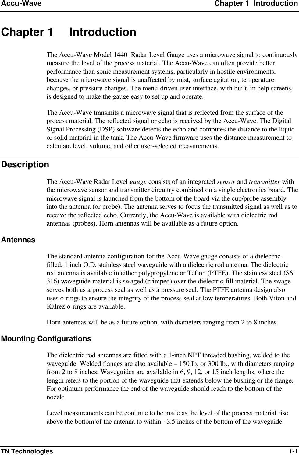
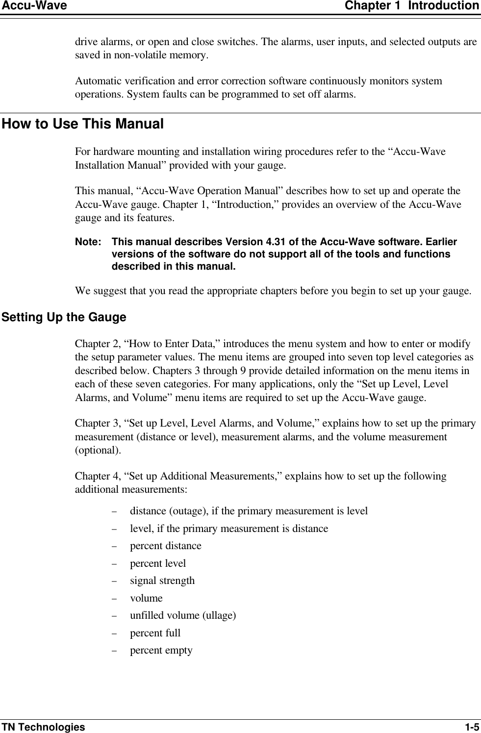
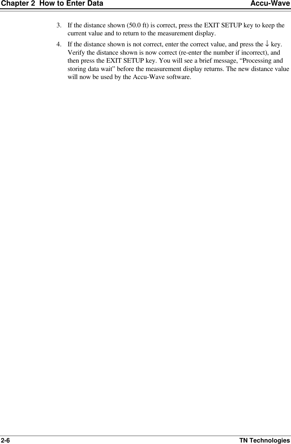
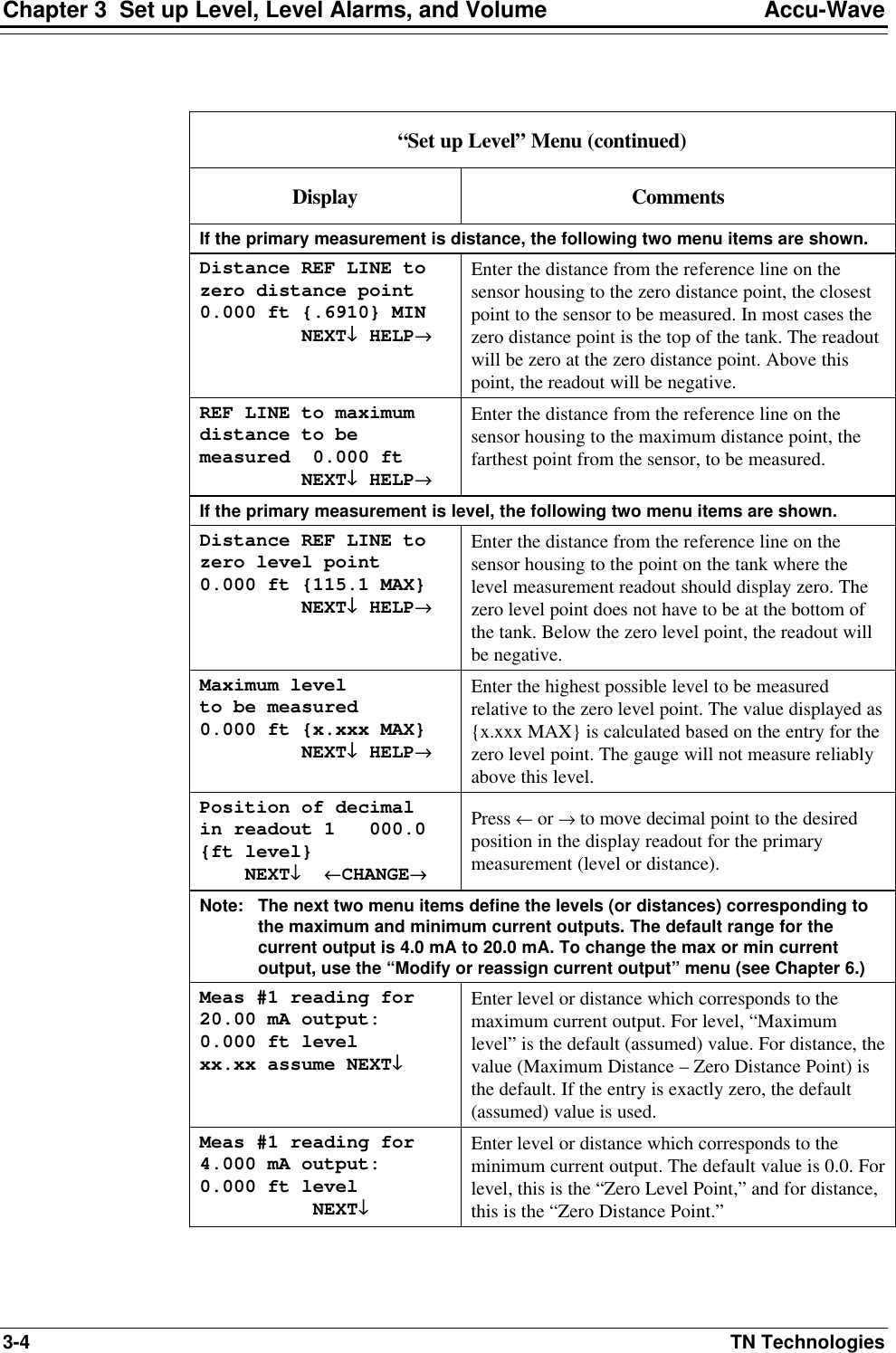
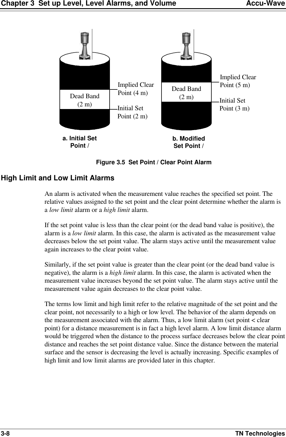
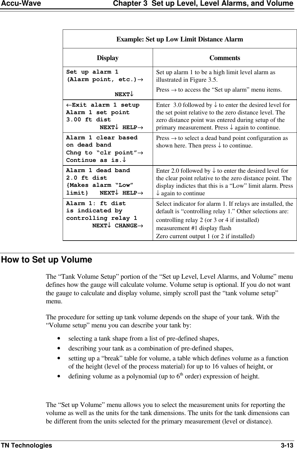
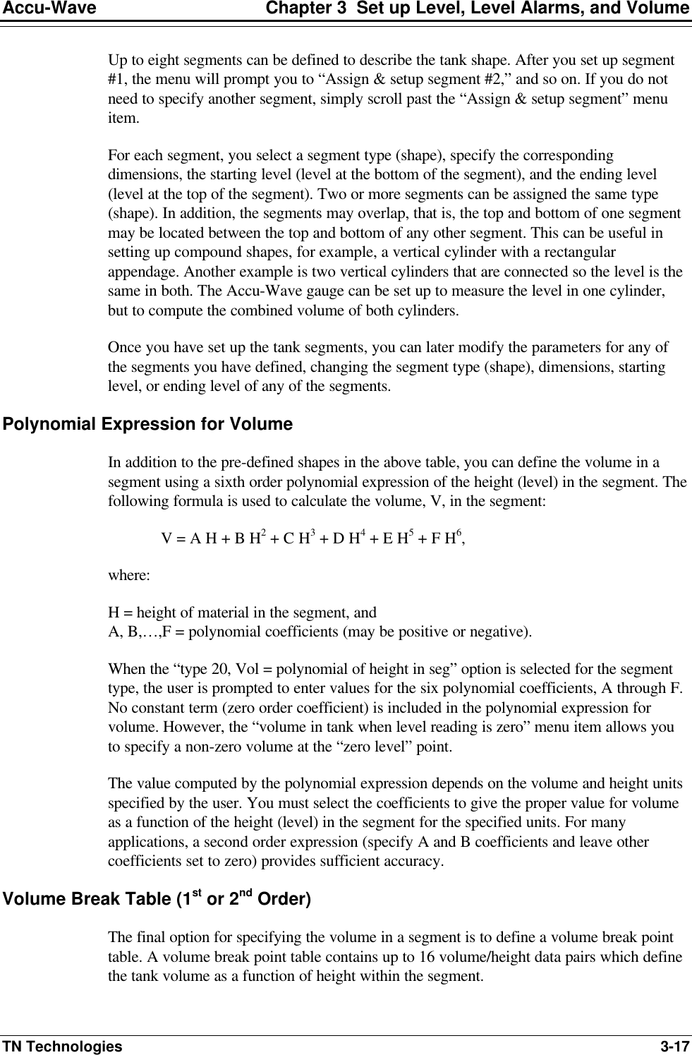
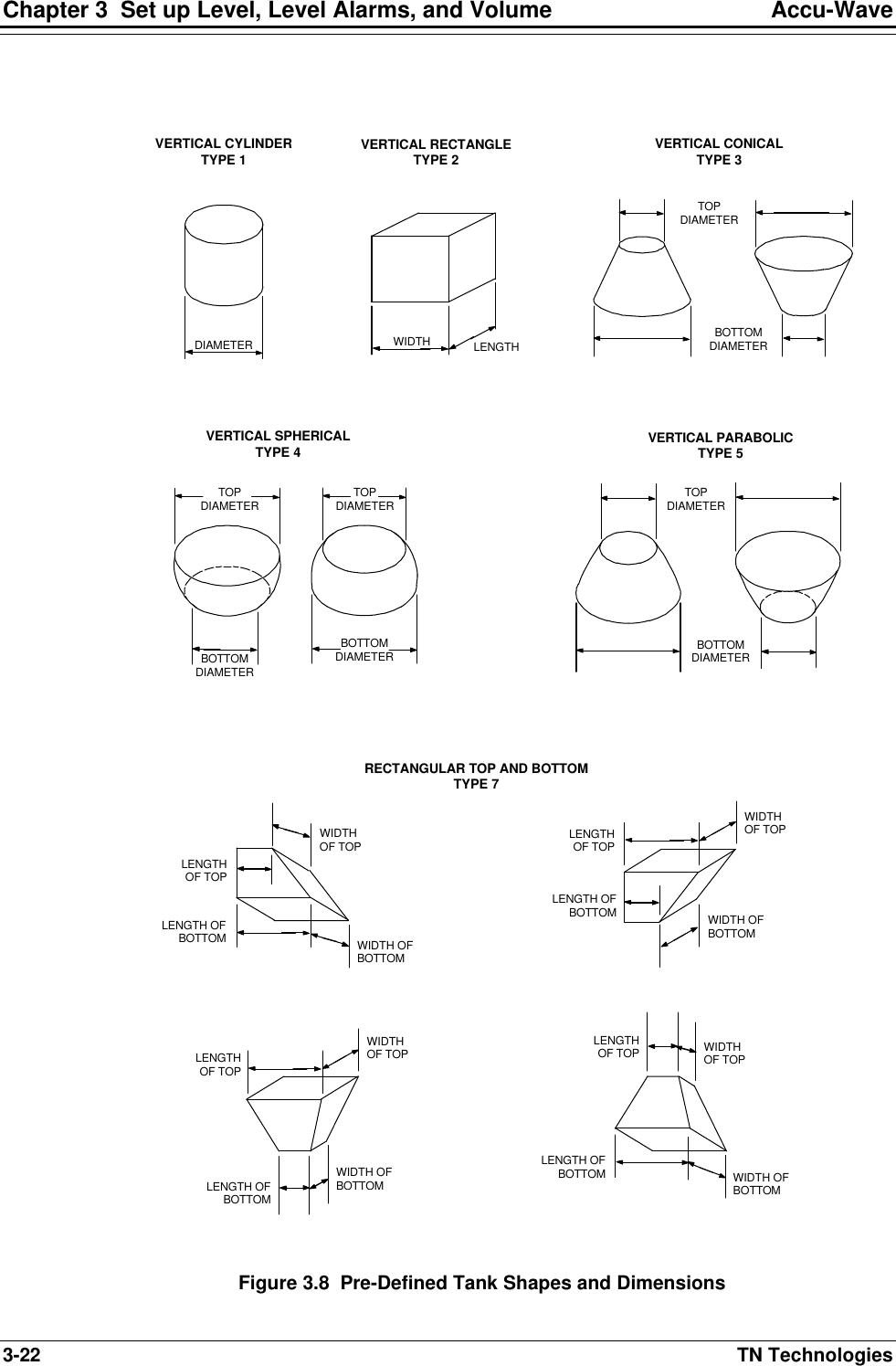
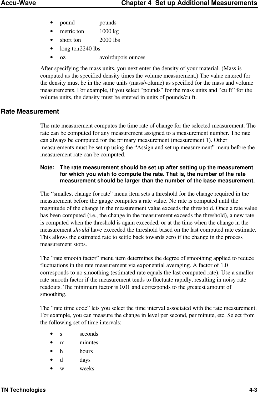
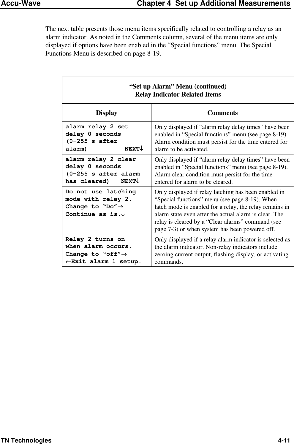
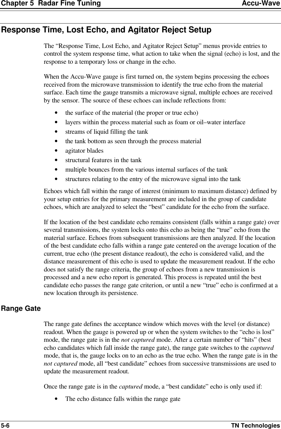
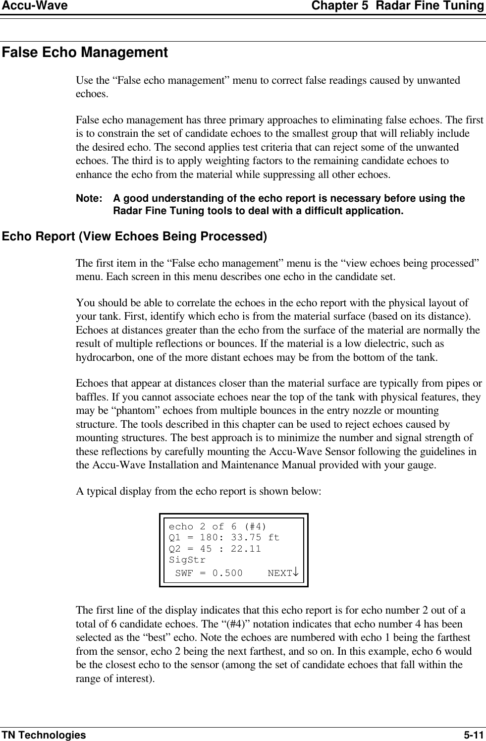
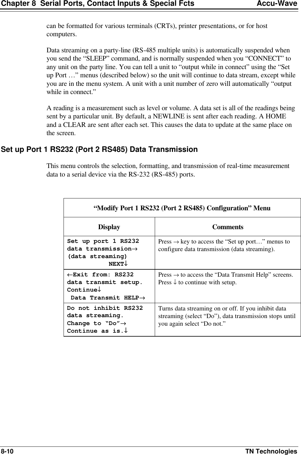
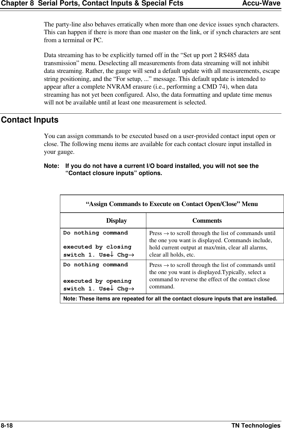
![Chapter 5 Radar Fine Tuning Accu-Wave 5-10 TN Technologies “Response Time, Lost Echo and Agitator Reject Setup” Menu (continued) Display Comments Increase range gate height by 0.000% of distance to surface NEXT↓↓ [Service only item] This variable can be used to increase the range gate hieght by a percent of the distance to the surface. Direct Entry Code: ‘043003’ weighting factor (GWF) for echoes inside range gate. 0.000 NEXT↓↓ [Service only item] During the echo selection process, echoes within the range are weighted by the preference factor. If this variable is set to 0.000 (default), no additional preference is given to echoes within the range gate. Entering a value greater than 1.0 will help the gauge track the process material. Direct Entry Code: ‘064003’ Capture range gate after 0 “hits” {128 assumed} NEXT↓↓ [Service only item] This is the number of hits within the range gate window before the gauge would enter capture mode. If this variable is set to 0.000 (default), the gauge will use a default value of 32 times the value set for the time constant. Direct Entry Code: ‘011004’ Do un-capture range gate @ timeout Change to “Do not” NEXT↓↓ [Service only item] If gauge does accept an echo within the range gate within the agitator reject time, the variable instructs either “Do” or “Do not” remain in capture mode. “Do not” would mean the range gate window would not be used until capture mode is re-established. Direct Entry Code: ‘040050’ disable range gate until re-capture ←←Exit this menu NEXT↓↓ EXECUTE CMD→→ [Service only item] Executing this command will disable the range gate until capture mode is re-established. This command is useful if a large Preference Factor or a long Agitator Reject Time is preventing the gauge from requiring the correct echo (process material). Direct Entry Code: ‘37’ (Command) Do not bypass range gate for near echoes. Change to “Do”→→ Continue as is.↓↓ Open the range gate to closer echoes. Direct Entry Code: ‘029040’ Do not bypass range gate for far echoes. Change to “Do”→→ Continue as is.↓↓ Open the range gate to farther echoes. Direct Entry Code: ‘029050’ Do not bypass range gate for all echoes. Change to “Do”→→ Continue as is.↓↓ Open the range gate to all echoes. Direct Entry Code: ‘029080’](https://usermanual.wiki/Thermo-MeasureTech/1440-15.Operating-Manual-for-1440/User-Guide-91777-Page-66.png)
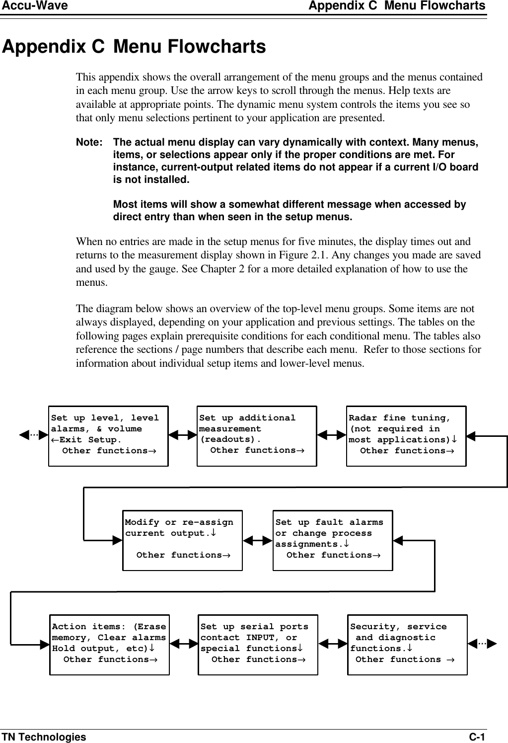
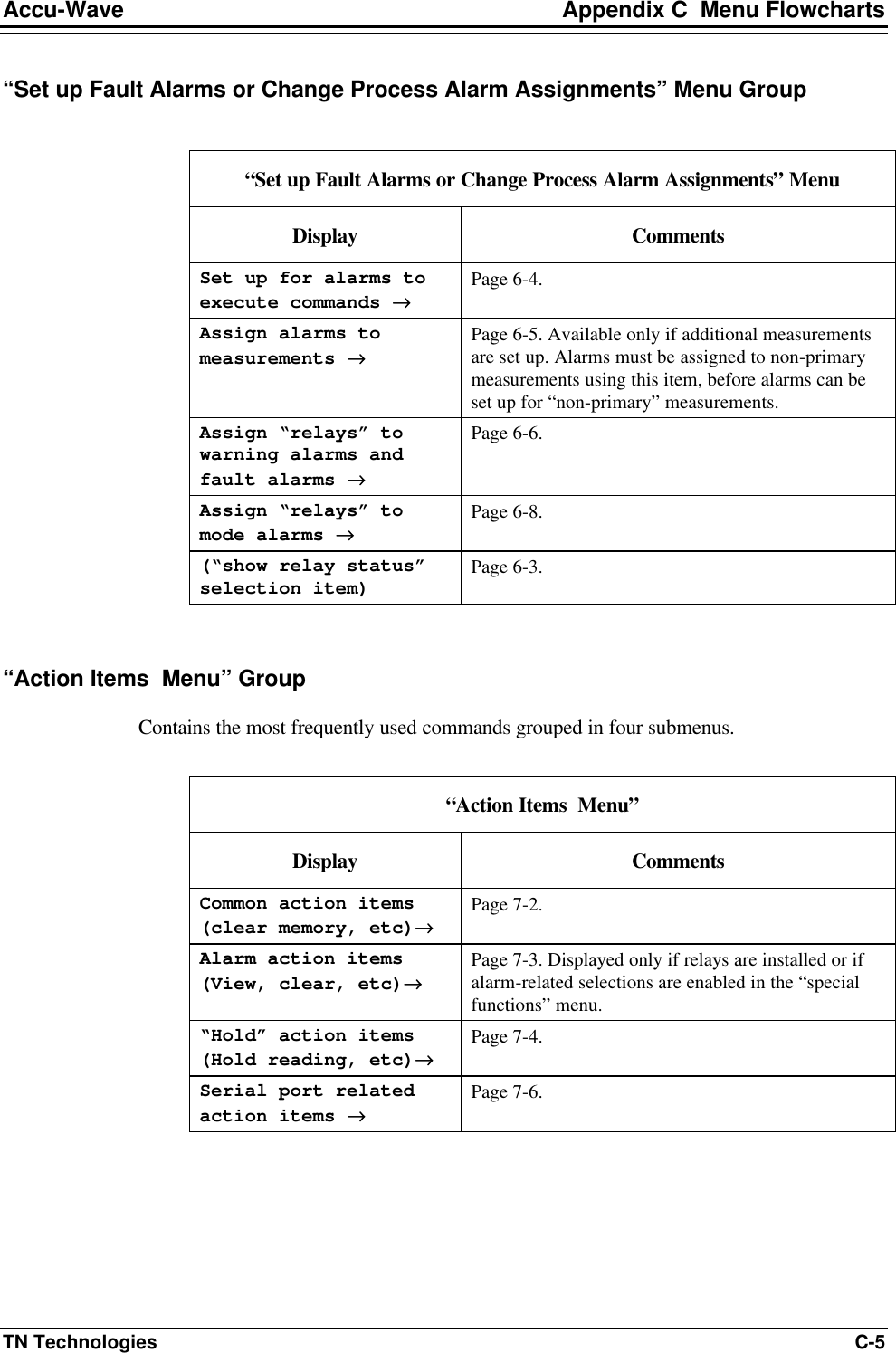
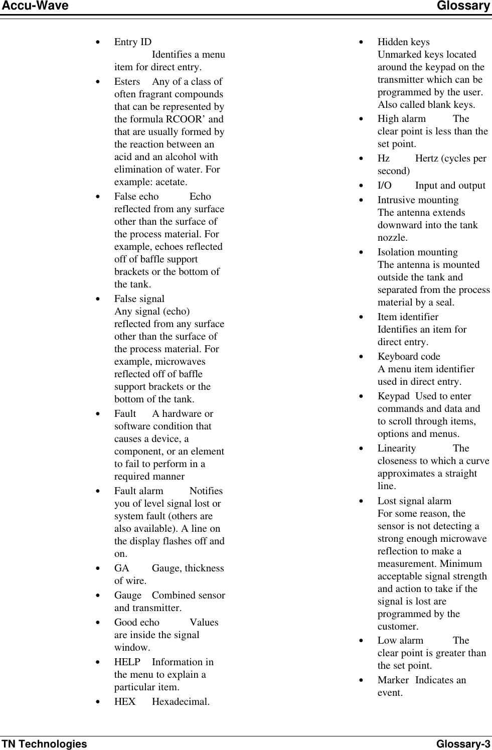
![Accu-Wave Chapter 5 Radar Fine Tuning TN Technologies 5-15 “False Echo Management” Menu Display Comments View echoes being processed→→ NEXT↓↓ Allows you to examine the echo report for each echo within the range of interest. Press → to access the echo reports, then press ↓ to scroll through the echo reports. The echo report is described on page 5-11. echo amplitude successive weighting factor(SWF)=.5000 NEXT↓↓ HELP→→ The successive weighting factor is applied to the signal strength of each echo before it is compared to the next closer echo. The same weighting factor is used for each echo. This is part of the process of selecting the “best candidate.” Direct Entry Code: ‘007003’ Minimum allowable signal strength 3.000 NEXT↓↓ HELP→→ Only echoes with a signal strength equal or greater than this value will be reported as a possible candidate. Direct Entry Code: ‘108003’ maximum desirable signal strength 0.000 NEXT↓↓ HELP→→ If this variable is set to 0.000 (default), the gauge will not use this function to reject echoes. If this variable is set to a non-zero value, the gauge will reject any echo greater than this value unless there are no other candidates. Used to reject strong unwanted echoes. Warning: If the desired echo exceeds this setting, the desired echo will be rejected unless it is the only candidate echo. Direct Entry Code: ‘104003’ maximum echo count to be processed 8 NEXT↓↓ HELP→→ This item limits the number of echoes which the gauge will process. Enter a value between 1 and 24. For the default value of 8, the strongest echoes (up to 8 maximum) which exceed the minimum allowable signal strength and which fall within the ROI are reported as candidate echoes. Direct Entry Code: ‘025004’ Reject echoes with Q1 below 0 NEXT↓↓ [Service only item] Enter minimum value for quality factor Q1 (0 - 255). If a non-zero value is entered, any candidate echo with a Q1 value less than this minimum value will be rejected. A 0 entry (default) disables the rejection of candidate echoes based on the Q1 value. Direct Entry Code: ‘043004’ Reject echoes with Q2 below 0 NEXT↓↓ [Service only item] Enter minimum value for quality factor Q2 (0 - 255). If a non-zero value is entered, any candidate echo with a Q2 value less than this minimum value will be rejected. A 0 entry (default) disables the rejection of candidate echoes based on the Q2 value. Direct Entry Code: ‘044004’](https://usermanual.wiki/Thermo-MeasureTech/1440-15.Operating-Manual-for-1440/User-Guide-91777-Page-71.png)
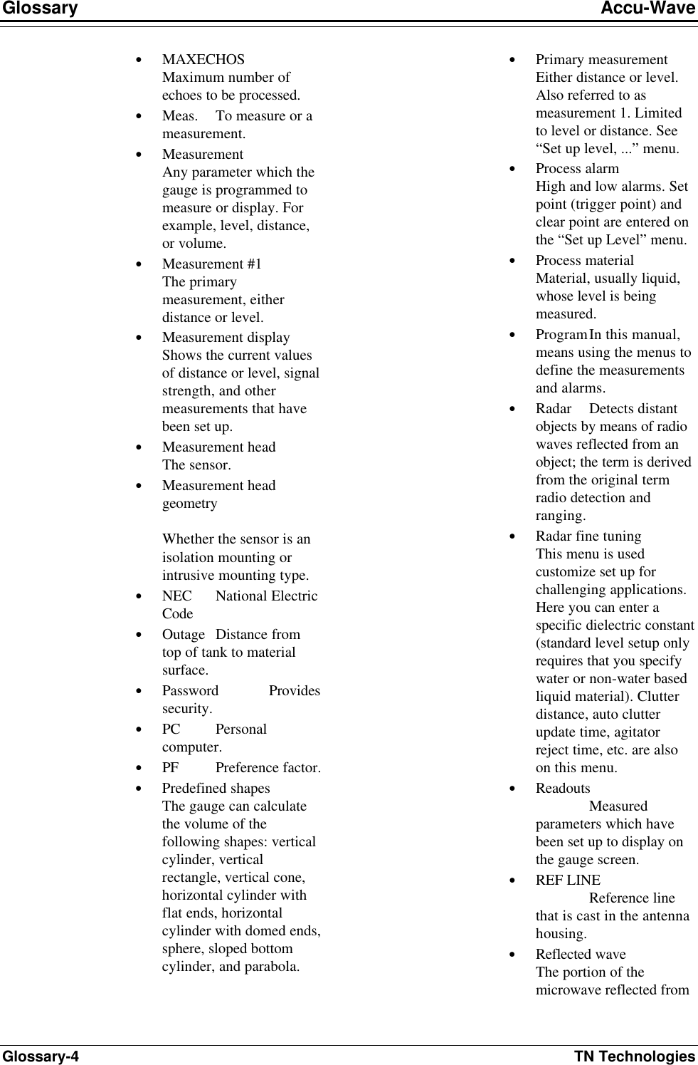
![Chapter 5 Radar Fine Tuning Accu-Wave 5-16 TN Technologies “False Echo Management” (continued) Display Comments bottom echo signal strength factor 0.000 NEXT↓↓ [Service only item] When set to 0.0 (default), this factor is not used in the echo selection process. When a non-zero value is entered, this weighting factor is applied to echoes at the “distance (from the) REF LINE to tank bottom” (next menu item) and beyond in the echo selection process. Note: Limit setting between 0.05 to 1.0. If this setting needs to be changed, consult TN. Direct Entry Code: ‘121003’ Distance REF LINE to tank bottom 0.000 ft NEXT↓↓ [Service only item] This item works in combination with the previous item. Direct Entry Code: ‘054003’ spectrum cutoff point 91.00 % NEXT↓↓ [Service only item] Do not modify this value. Clutter data management→→ NEXT↓↓ Press → to enter the “Clutter data management” submenu. See the next section for details. tank map setup→→ NEXT↓↓ [Service only item] Press → to enter the “tank map setup” submenu. This submenu is used to map and reject false echoes in an empty tank. See page 5-21 for details. region weighting setup→→ NEXT↓↓ [Service only item] Press → to enter the “region weighting setup” submenu. This submenu lets you divide the tank into regions (up to 8) and assign a different weighting factor to each region. See page 5-24 for details. Minimum allowable post weighting signal strength 0.000 NEXT↓↓ [Service only item] Enter desired threshold value. Default value of 0.0 disables this threshold test. When a non-zero value is entered, only echoes with a weighted signal strength greater than or equal to this value are reported as candidate echoes. dynamic threshold setup→→ NEXT↓↓ [Service only item] Press → to enter the “dynamic threshold setup” submenu. This submenu defines parameters which help track a turbulent process while still providing a quick and reliable update response. See page 5-26 for details.](https://usermanual.wiki/Thermo-MeasureTech/1440-15.Operating-Manual-for-1440/User-Guide-91777-Page-72.png)
![Accu-Wave Chapter 5 Radar Fine Tuning TN Technologies 5-19 “Clutter Data Management” Menu Display Comments Clutter distance {from REF LINE} 0.000 ft {7.826 MAX} NEXT↓↓ If this entry is 0.0, the Clutter Data Mgmt menu items will not be displayed. Maximum allowable clutter distance is 7.147 feet or 25% of the maximum measurement range, whichever is greater. When a clutter erase command is executed, clutter data is collected to the maximum clutter distance. The “Clutter distance” defines which portion (or all) of the clutter data will be removed from the spectrum. Do not disable Erase clutter Change to “Do”→→ Continue as is.↓↓ May be used to disable clutter erase for diagnostic purposes. Direct Entry Code: ‘041080’ Get clutter data & save result. ←←Exit this menu. NEXT↓↓ EXECUTE CMD→→ Press → to execute the “Get clutter data” command. The distance to the material surface must be greater than the clutter distance value, or the valid echo will be removed as clutter. The actual level can reach the clutter area during operation, but can not rise above any physical features associated with the clutter. Note: Clutter Erase is best performed when the tank level is low (but not empty) and the surface of the process material is being agitated. If the measurement range is over 27 ft (8m), you must redo the learn (get) clutter if you change measurement range. Direct Entry Code: ‘104’ service clutter items→→ NEXT↓↓ [Service only item] Provides an additional set of diagnostic tools, if service only items are enabled. See “Service Clutter Items” table below. Automatic clutter data update time 0 min NEXT↓↓ HELP→→ Automatic update of clutter data is activated by entering a non-zero time. If this entry is zero, clutter data update is performed by manual command only. When active, new clutter data is taken at the interval entered. The latest clutter data is saved to non-volatile memory every 4 hours or at the update interval, whichever is the longest. Note: Use auto update only when clutter can change over time due to buildup on the seal or nozzle. You should do a manual clutter data update before entering an auto update time.](https://usermanual.wiki/Thermo-MeasureTech/1440-15.Operating-Manual-for-1440/User-Guide-91777-Page-75.png)
![Chapter 5 Radar Fine Tuning Accu-Wave 5-20 TN Technologies “Service Clutter Items” Menu [“Service Only Items” must be enabled] Display Comments ←←Exit from: service clutter items NEXT↓↓ HELP→→ Provides an additional set of diagnostic tools, if “service only items” are enabled. clutter spectrum count to average 8 {1 – 64} NEXT↓↓ Number of clutter spectrum values to average. Default value is 8. Gain: now 1.252 clutter 1.252 stored 1.252 (read only) NEXT↓↓ gain: Preamp gain in use now. clutter: Preamp gain in use when clutter data now in use was taken. stored: Preamp gain stored in NVRAM. cm/tic: now 1.488E-2 clutter 1.488E-2 stored 1.488E-2 (read only} NEXT↓↓ now: Range slope (cm/tic) factor in use now. clutter: Range slope factor in use when clutter data now in use was taken. stored: Range slope factor stored in NVRAM. temp disable Erase clutter ←←Exit this menu. NEXT↓↓ EXECUTE CMD→→ Will not show up if “disable” clutter erase has been selected in the main clutter management menu. This is a toggle HOLD command which disables clutter erase. If hold mode is “disable” clutter erase, this command will show up as “enable.” Get clutter data when dist > 6.984 ft ←←Exit this menu. NEXT↓↓ EXECUTE CMD→→ Arms system to get clutter data when level goes below clutter distance. Get clutter data do not save result. ←←Exit this menu. NEXT↓↓ EXECUTE CMD→→ Collects clutter data for current use but does not write over stored data. Load & use stored clutter data ←←Exit this menu. NEXT↓↓ EXECUTE CMD→→ Puts stored clutter data into use (instead of that collected above). Save clutter data ←←Exit this menu. NEXT↓↓ EXECUTE CMD→→ Stores clutter data collected above. saved clutter data→→ NEXT↓↓ View saved clutter data values, real and imaginary clutter values.](https://usermanual.wiki/Thermo-MeasureTech/1440-15.Operating-Manual-for-1440/User-Guide-91777-Page-76.png)
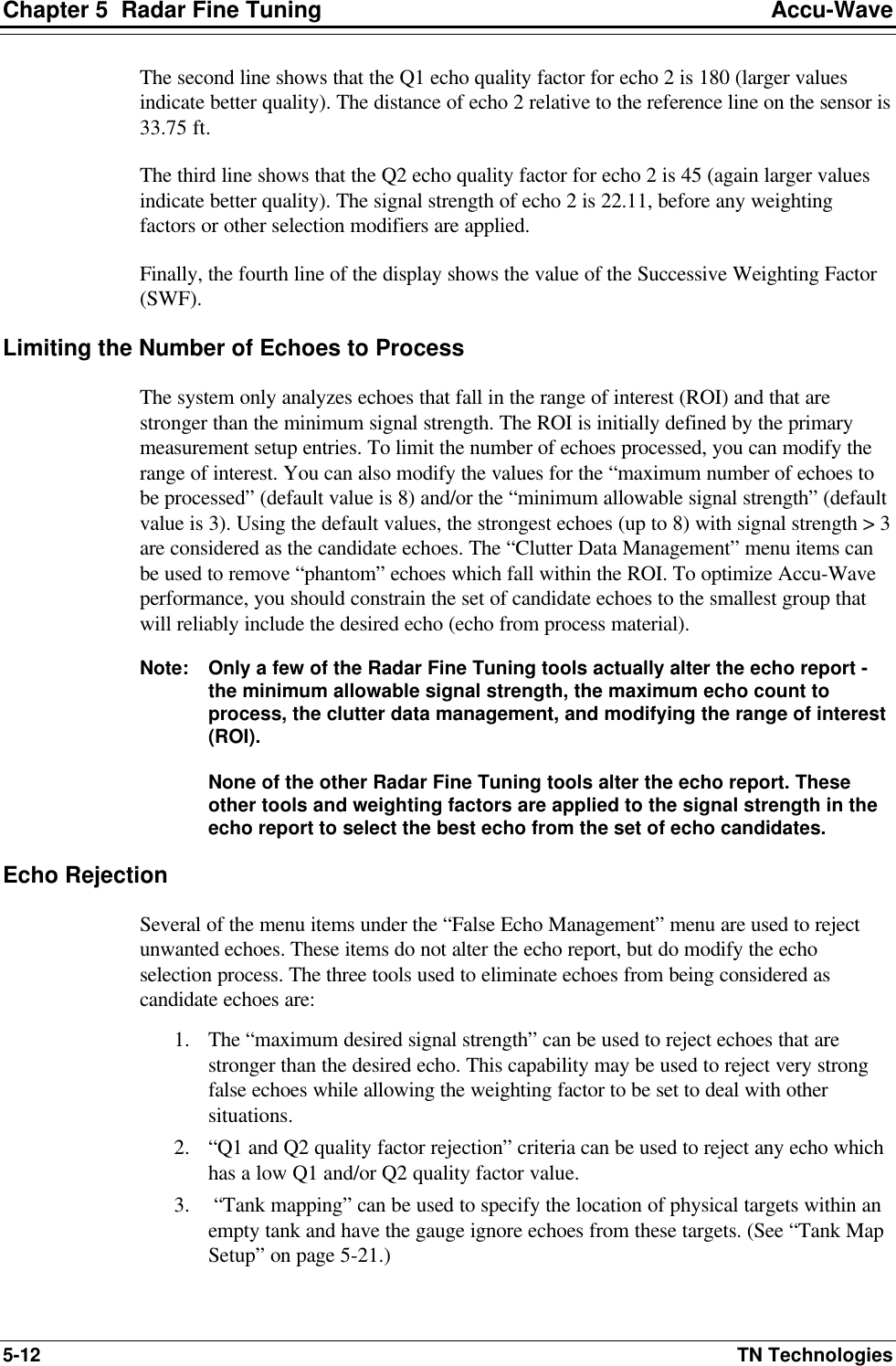
![Chapter 5 Radar Fine Tuning Accu-Wave 5-22 TN Technologies User Considerations If the tank is not quite empty or you do not want to map the tank bottom, it is essential that the user-entered map distance be at least 30 cm (1 ft) above the level of the process material (or tank bottom) while the tank map data is taken. If both the tank mapping and clutter erase tools are being utilized, the clutter erase data must be acquired prior to tank mapping. Note: The “Tank Map Setup” menu structure appears only if “Service Only Items” are enabled. Direct Entry Code 025020. The direct entry codes were intentionally omitted from this table. Use the “Tank Map Setup” menu to set up this tool. “Tank Map Setup” Menu [“Service Only Items” must be enabled] Display Comments Do not enable tank mapping Change to “Do”→→ Continue as is.↓↓ When set to the default value of “Do not enable tank mapping,” the menu items below are not displayed. Change to “Do” to enable tank mapping. Reset to “Do not” at any time to disable tank mapping. Direct Entry Code: ‘026040’ maximum distance to map for false echoes 0.000 ft 25.25 assume NEXT↓↓ Set maximum distance to be mapped. Default or assumed value is ~7.5 cm (0.25 ft) past the maximum distance to be measured. If the tank is not completely empty, the map distance must be less than the distance from the REF LINE to the process material surface. Map empty tank for false echoes ←←Exit this menu. NEXT↓↓ EXECUTE CMD→→ This command maps the tank for false echoes such as ladders, beams, baffles, etc. (not agitator blades). false echo window 1% of max distance NEXT↓↓ Set “false echo window” value, the first of three criteria used to determine if an echo is a hit (corresponds to a mapped echo). The default value is 1% of maximum distance. map Q1 tol 32 NEXT↓↓ Set tolerance of the Q1 quality factor, the second of three criteria used to determine if an echo is a hit (corresponds to a mapped echoes). The default is 32, meaning the Q1 value of the report echo must be within 32 of the Q1 value of the corresponding mapped echo to be considered a possible hit. Note: The third criteria is the signal strength, which must be within a factor of 2 of the signal stremgh of the mapped echo.](https://usermanual.wiki/Thermo-MeasureTech/1440-15.Operating-Manual-for-1440/User-Guide-91777-Page-78.png)
![Chapter 5 Radar Fine Tuning Accu-Wave 5-24 TN Technologies “Tank Map Setup” Menu (cont.) [“Service Only Items” must be enabled] Display Comments ignore mapped echoes Change to “derate”→→ Continue as is↓↓ Echoes corresponding to a mapped echo (echoes that meet all three “hit” criteria) can either be ignored or “derated” by a weighting factor. The default is to ignore all hits. Map echo weighting factor (MWF) 5.000e-2 NEXT↓↓ This menu item is only displayed if the above item was changed from “ignore to “derate.” Do not allow echoes shorter than map hit Change to “Do”→→ Continue as is.↓↓ The default is “Do not.” This means the gauge will not consider any reported echoes closer than the farthest map hit to be a possible candidate echo. Note: After executing the “Map empty tank for false echoes” command, a series of menu item will be displayed describing the mapped echoes. map echo #1 of 5 17.77 ft distance signal str=5.781 Q1=129 NEXT↓↓ Information for each mapped echo is displayed: distance from REF LINE to echo, signal strength, and quality factor (Q1) Region Weighting Setup This menu allows the user to divide the tank into regions (2 to 8) and assign a custom weighting factor to each of the regions. The user enters the distances at which the adjacent regions intersect. The first region starts at the REF LINE, and the last region ends pass the maximum distance point. These custom weighting factors work in combination with the other echo weighting or preference factors. The region weighting factors do not parse the echoes within the region; instead all of the echoes within the region are simply weighted by its regional weighting factor. The regional weighting factors are applied to the echo candidates prior to parsing with the default echo weighting factor. Note: The weighted echo values can be monitored by assigning special code ‘1062’ as an additional measurement. The region weighting factors do not alter the echo report. The “Region Weighting Setup” menu structure only appears if “Service Only Items” are enabled- Direct Entry Code 025020. The direct entry codes were intentionally omitted from this Table. Use the “Region Weighting Setup” menu structure to set up this set of tools.](https://usermanual.wiki/Thermo-MeasureTech/1440-15.Operating-Manual-for-1440/User-Guide-91777-Page-80.png)
![Accu-Wave Chapter 5 Radar Fine Tuning TN Technologies 5-25 “Region Weighting Setup” Menu [“Service Only Items” must be enabled] Display Comments Do not enable region weighting Change to “Do”→→ Continue as is.↓↓ When set to default value of “Do not enable region weighting,” the menu items below are not displayed. Change to “Do” to enable region weighting. Reset to “Do not” at any time to disable region weighting. Direct Entry Code: ‘026050’. number of weighted regions 3 {2 to 8} NEXT↓↓ The default is 2 regions, meaning the tank will be divided into 2 regions. A maximum of 8 regions is allowed. Note: A separate menu item will be displayed to define the extent of each region, except the last region. The first region always begins at the REF LINE (0.000). The boundaries of the last region are defined by the farther boundary of the next-to-last region and the maximum distance point. region 1 Distance 0.000 to 10.00 ft NEXT↓↓ Enter far boundary for region 1 (10.00 ft in this example). The next region begins at the far boundary of the previous region and ends at the user-entered value. The accuracy of the regional boundary entries are the greater of the max_distance/256 or 1.5 inches. region 2 Distance 10.00 to 15.00 ft NEXT↓↓ Enter far boundary for region 2 (15.00 ft in this example), and so on. Only 3 regions were specified in this example. The boundary of the third (last) region is defined by farther boundary of region 2 and the maximum distance point. Note: Following menu items prompt for the desired weighting factor for each region. The region weighting factors (RWFs) work in combination with the other echo weighting factors. The RWFs do not alter the echo report. region 1 {RWF(1) 0.000 to 10.00 ft} factor 1.000 NEXT↓↓ A separate weighting factor can be assigned to each of the regions. region 2 {RWF(2) 10.00 to 15.00 ft} factor 1.000 NEXT↓↓ Enter region 2 weighting factor. region 3 {RWF(3) 15.00 to 20.71 ft} factor 1.000 NEXT↓↓ Enter weighting factor for region 3 (the last region in this example).](https://usermanual.wiki/Thermo-MeasureTech/1440-15.Operating-Manual-for-1440/User-Guide-91777-Page-81.png)
![Chapter 5 Radar Fine Tuning Accu-Wave 5-26 TN Technologies Dynamic Threshold Setup Note: The “Dynamic Threshold Setup” menu items are only displayed when the “Service Only Items” are enabled. Direct Entry Code 025020. If the dynamic threshold setup is required, the Agitator Reject Time (Direct Entry Code 044003) should be increased to 8 seconds or longer. Setting a dynamic threshold is intended to help track a turbulent process. When the surface of the process material is turbulent or agitated, the amplitude of the echo from the process material will fluctuate randomly. Setting a dynamic threshold will assist the gauge in accepting a reliable (strong) return, while still providing a quick and reliable update of the material surface level (or distance) measurement. The amplitude of the previously accepted echo and two user-entered parameters are used to dynamically set the minimum amplitude (signal strength) of the next acceptable echo. The two parameters are: • Dynamic Threshold Base - A constant (K), which is used to set the base value of the dynamic threshold using the equation dynamic threshold = amplitude of the last accepted echo/2K . • Change Dynamic Threshold Factor - Each second that the gauge operates without getting an acceptable echo, the dynamic threshold is multiplied by this factor. These two parameters decrease the level of the dynamic threshold since the multiplication factor is less than 1. After the gauge acquires an acceptable echo, the dynamic threshold process starts over with the initial or baseline dynamic threshold value being set based on the amplitude of the last accepted echo and the dynamic threshold base factor. The rate at which the Dynamic Threshold changes can be smoothed by changing one or both of the dynamic threshold smoothing factors. The “increase smoothing factor” (ISF) is applied if the new base threshold value is greater than the old threshold. In this case the dynamic threshold will be computed as: thresholdold + [ISF x (thresholdnew – thresholdold)]. The “decrease smoothing factor” (DSF) is applied if the new base threshold value is less than the old threshold. In this case the dynamic threshold will be computed as: thresholdold + [DSF x (thresholdnew – thresholdold)].](https://usermanual.wiki/Thermo-MeasureTech/1440-15.Operating-Manual-for-1440/User-Guide-91777-Page-82.png)
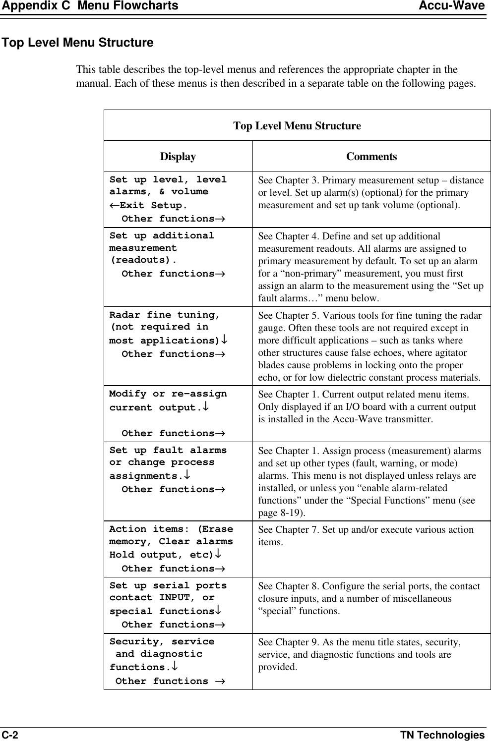
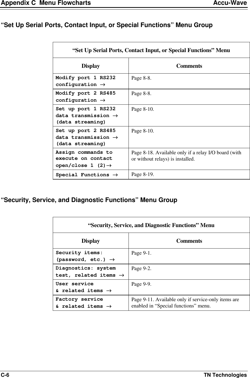
![Accu-Wave Chapter 5 Radar Fine Tuning TN Technologies 5-27 “Dynamic Threshold Setup” Menu [“Service Only Items” must be enabled] Display Comments Do not enable dynamic threshold Change to “Do”→→ Continue as is.↓↓ When set to default value of “Do not enable dynamic threshold,” the menu items below are not displayed. Change to “Do” to enable dynamic threshold. Reset to “Do not” at any time to disable dynamic threshold. Direct Entry Code: ‘026060’ Change dynamic threshold by .8000 each sec NEXT↓↓ If there is no acceptable echo with an amplitude greater than the present value of the dynamic threshold, the dynamic threshold is decreased by the factor entered here (value must be less than 1.0). Direct Entry Code: ‘010003’ dynamic threshold base= signal str/2^1 NEXT↓↓ The initial baseline value of the dynamic threshold is set at the amplitude of the previously accepted echo divided by 2K. Enter the value of the exponent K. For example, if 3 is entered, the initial baseline value will be 1/8 (1/23) of the amplitude of the previously accepted echo. Direct Entry Code: ‘058004’ Dynamic threshold increase smoothing factor 1.000 {0.001 to 1.0} NEXT↓↓ Enter value for the “increase smoothing factor” (ISF). Default value is 1.0 or no smoothing. If the new base threshold value is greater than the old threshold, the base value of the dynamic threshold will be equal to: thresholdold + [ISF x (thresholdnew – thresholdold)] Direct Entry Code: ‘149013’ Dynamic threshold decrease smoothing factor 1.000 {0.001 to 1.0} NEXT↓↓ Enter value for the “decrease smoothing factor” (DSF). Default value is 0.1. If the new base threshold value is less than the old threshold, the base value of the dynamic threshold will be equal to: [thresholdold + [DSF x (thresholdnew – thresholdold)] Direct Entry Code: ‘149023’ Overall echo selection process Note: The following example illustrates how the Radar Fine Tuning tools work in combination with one another. It is not intended to reflect the setup of a typical application. Range of Interest (ROI) Setup: • Primary Measurement: Level • Distance REF LINE to zero level point: 25.00 ft](https://usermanual.wiki/Thermo-MeasureTech/1440-15.Operating-Manual-for-1440/User-Guide-91777-Page-83.png)
![Chapter 7 Action Items Accu-Wave 7-6 TN Technologies Serial Port Related Action Items “Serial Port Related Action Items” Menu Display Comments serial port related action items→→ NEXT↓↓ Press → to enter the “Hold action items” menu. Press ↓ to return to main heading for the “Action Items…” menu group update data output to port 1, RS232 ←←Exit this menu. NEXT↓↓ EXECUTE CMD→→ Sends a data set (as defined by serial transmit setup or default) to RS-232 port. update data output to port 2, RS485 ←←Exit this menu. NEXT↓↓ EXECUTE CMD→→ Sends a data set (as defined by serial transmit setup or default to RS-485 port. clear flgs-buff RS232 ←←Exit this menu. NEXT↓↓ EXECUTE CMD→→ [Service only item.] clear flgs-buff RS485 ←←Exit this menu. NEXT↓↓ EXECUTE CMD→→ [Service only item.] dump setup data via port 1, RS232 ←←Exit this menu. NEXT↓↓ EXECUTE CMD→→ Available only if “Serial dump items” have been enabled in the “Special Functions” menu. This item allows the gauge’s current setup to be dumped to the RS-232 serial port. Requires special purpose program. dump setup data via port 2, RS485 ←←Exit this menu. NEXT↓↓ EXECUTE CMD→→ Same as previous item, except for RS-485 port. Requires TNComm software or other special purpose program. retrieve setup data via port 1, RS232 ←←Exit this menu. NEXT↓↓ EXECUTE CMD→→ Available only if “Serial dump items” have been enabled in the “Special Functions” menu. This item retrieves the gauge’s setup data dumped to the RS-232 serial port using the “dump setup data” command. Requires special purpose program. retrieve setup data via port 2, RS485 ←←Exit this menu. NEXT↓↓ EXECUTE CMD→→ Same as previous item, except for RS-485 port. Requires TNComm software or other special purpose program.](https://usermanual.wiki/Thermo-MeasureTech/1440-15.Operating-Manual-for-1440/User-Guide-91777-Page-98.png)
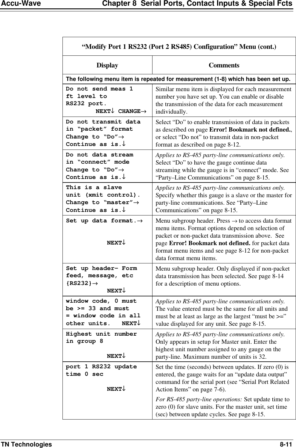
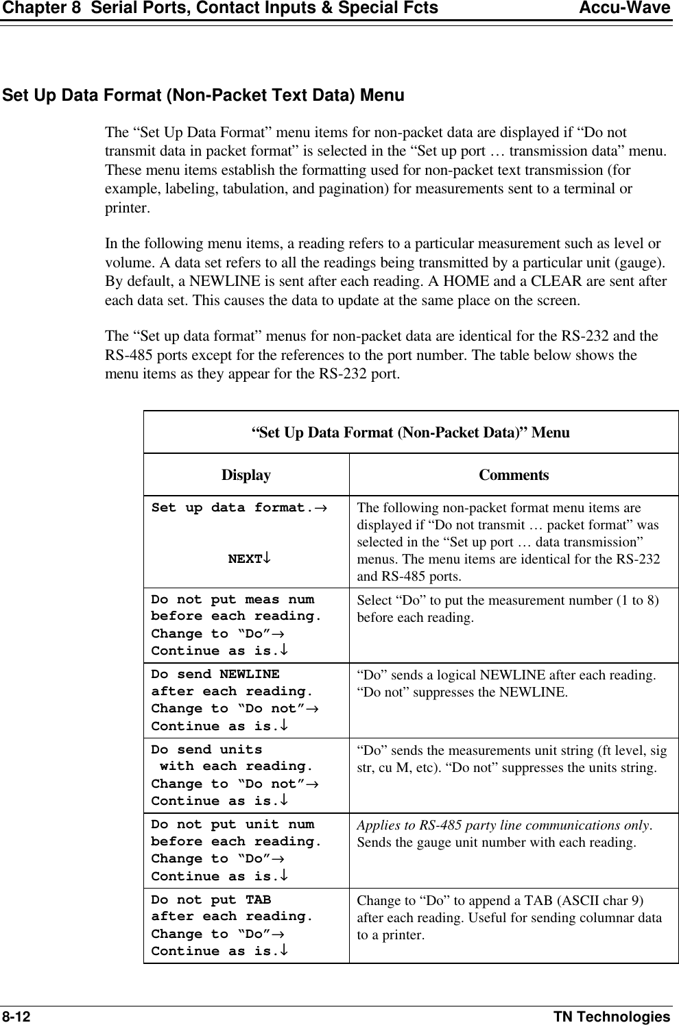
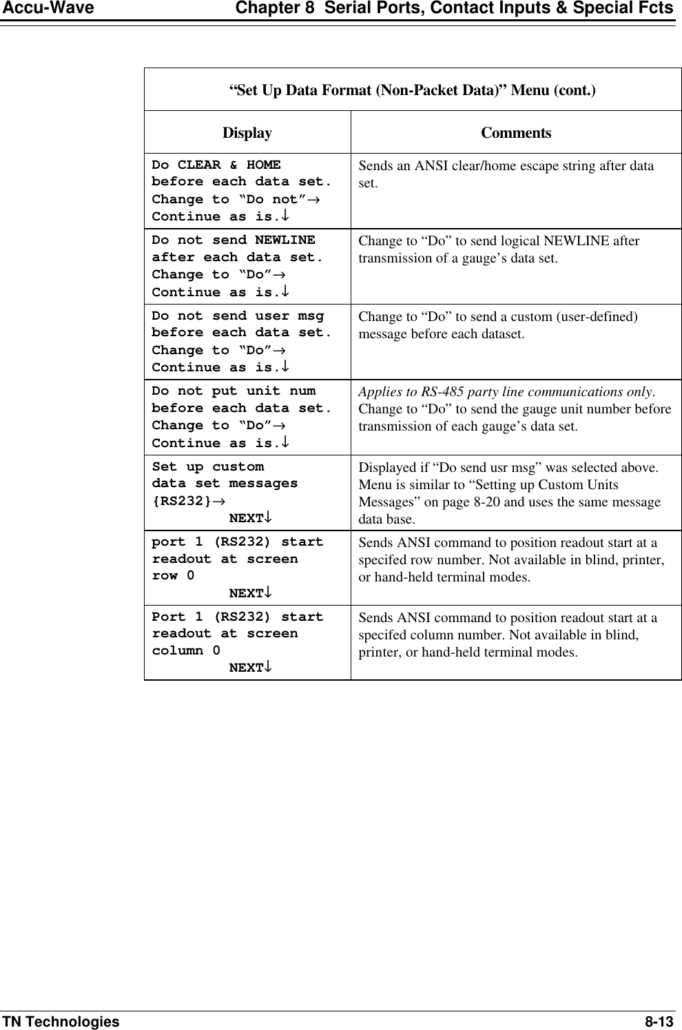
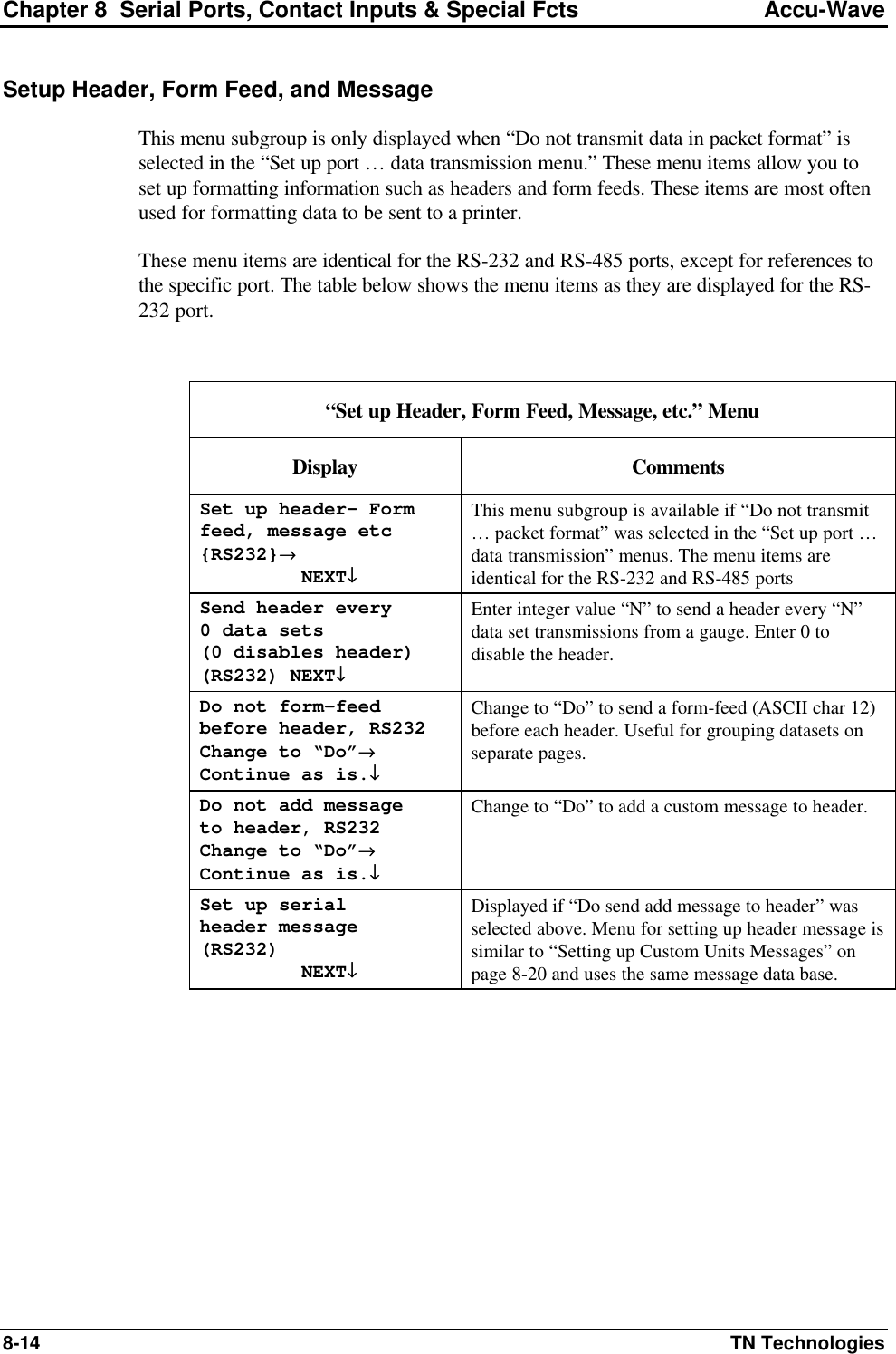
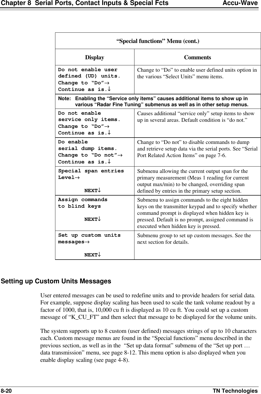
![Accu-Wave Chapter 8 Serial Ports, Contact Inputs & Special Fcts TN Technologies 8-19 Special Functions “Special functions” Menu Display Comments Do not enable alarm related selections Change to “Do”→→ Continue as is.↓↓ Displayed if no relays are installed. Change to “Do” to enable the alarm-related menu selections throughout the setup menus. Do not enable alarm relay delay times. Change to “Do”→→ Continue as is.↓↓ Only displayed if relays are installed. Change to “Do” to enable relay alarm delay time entries in menus which set up process limit alarms. Do not make relay latching available Change to “Do”→→ Continue as is.↓↓ Only displayed if relays are installed. Change to “Do” to enable relay latch mode entries in menus which set up process limit alarms. Do not disable “For setup”, etc. display Change to “Do”→→ Continue as is.↓↓ Change to “Do” to suppress the message on line 4 (warnings and setup direction) of the normal readout. This allows all four lines to be used for measurement readouts. Do not show relay status on readout. Change to “Do”→→ Continue as is.↓↓ Change to “Do” to display relay status on mesaurement display. The numbers of the relays currently turned on are displayed along with the normal measurement readouts. Do not disable display of fault msg Change to “Do”→→ Continue as is.↓↓ [Service only item.] Change to “Do” to disable display of system fault messages. Do not disable dynamic tracking Change to “Do”→→ Continue as is.↓↓ Leave this item set to “Do not” so that dynamic tracking remains enabled. Dynamic tracking threshold 0.000 f (if 0, assumes half range gate) NEXT↓↓ [Service only item.] Controls dynamic tracking threshold. Typically leave this value set at 0.0, so default threshold (half range gate) is used. Do not disable “sig str” readout Change to “Do”→→ Continue as is.↓↓ Change to “Do” to disable display of signal strength. This will make display space (one line) available for another readout.](https://usermanual.wiki/Thermo-MeasureTech/1440-15.Operating-Manual-for-1440/User-Guide-91777-Page-111.png)
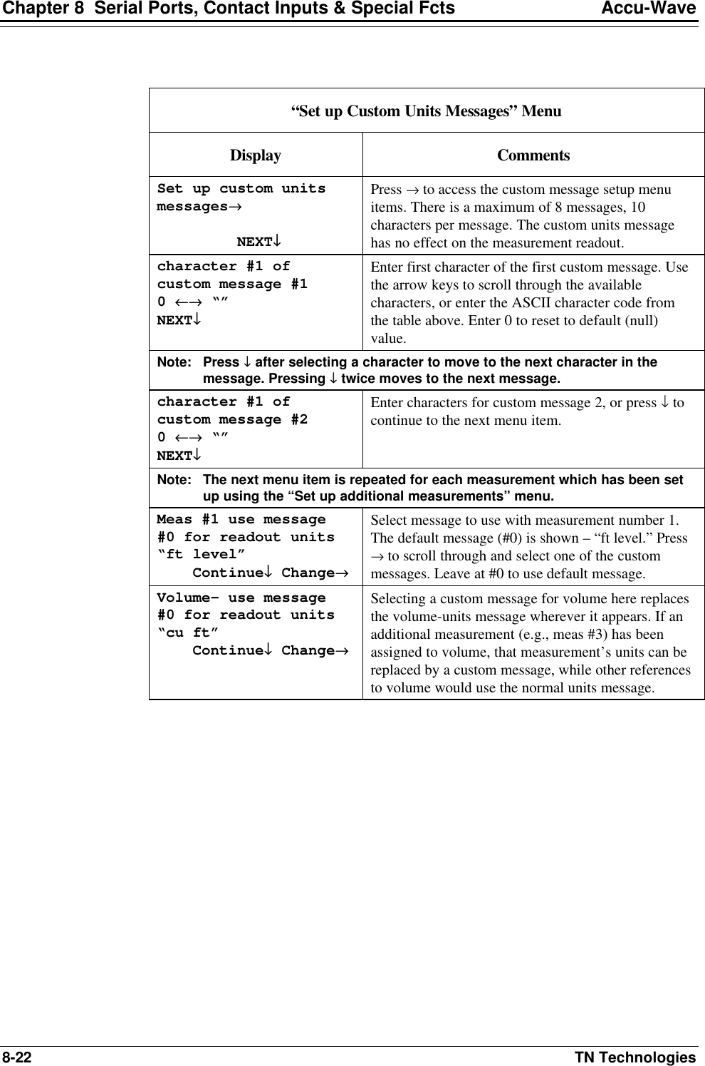
![Accu-Wave Chapter 8 Serial Ports, Contact Inputs & Special Fcts TN Technologies 8-21 In each case, you can access any of the custom messages which have been entered. You can modify an existing message or add a new message, and then select which message to use for a particular purpose. You enter message characters by using the right and left arrow keys to scroll through the available character selections or by using the ASCII codes for the characters given in the table below. The entry screen for each character shows the rest of the 10 character message to provide context for your selection. Note: Enter a value of 0 (zero) for the first character to reset the message to the null string, the default value. 32 SP(ace) 51 3 70 F 89 Y 108 l 33 ! 52 4 71 G 90 Z 109 m 34 " 53 5 72 H 91 [ 110 n 35 # 54 6 73 I 92 ¥ 111 o 36 $ 55 7 74 J 93 ] 112 p 37 % 56 8 75 K 94 ^ 113 q 38 & 57 9 76 L 95 _ 114 r 39 ’ 58 : 77 M 96 ` 115 s 40 ( 59 ; 78 N 97 a 116 t 41 ) 60 < 79 O 98 b 117 u 42 * 61 = 80 P 99 c 118 v 43 + 62 > 81 Q 100 d 119 w 44 , 63 ? 82 R 101 e 120 x 45 - 64 @ 83 S 102 f 121 y 46 . 65 A 84 T 103 g 122 z 47 / 66 B 85 U 104 h 123 { 48 0 (zero) 67 C 86 V 105 I 124 | 49 1 68 D 87 W 106 j 125 } 50 2 69 E 88 X 107 k 126 →](https://usermanual.wiki/Thermo-MeasureTech/1440-15.Operating-Manual-for-1440/User-Guide-91777-Page-113.png)
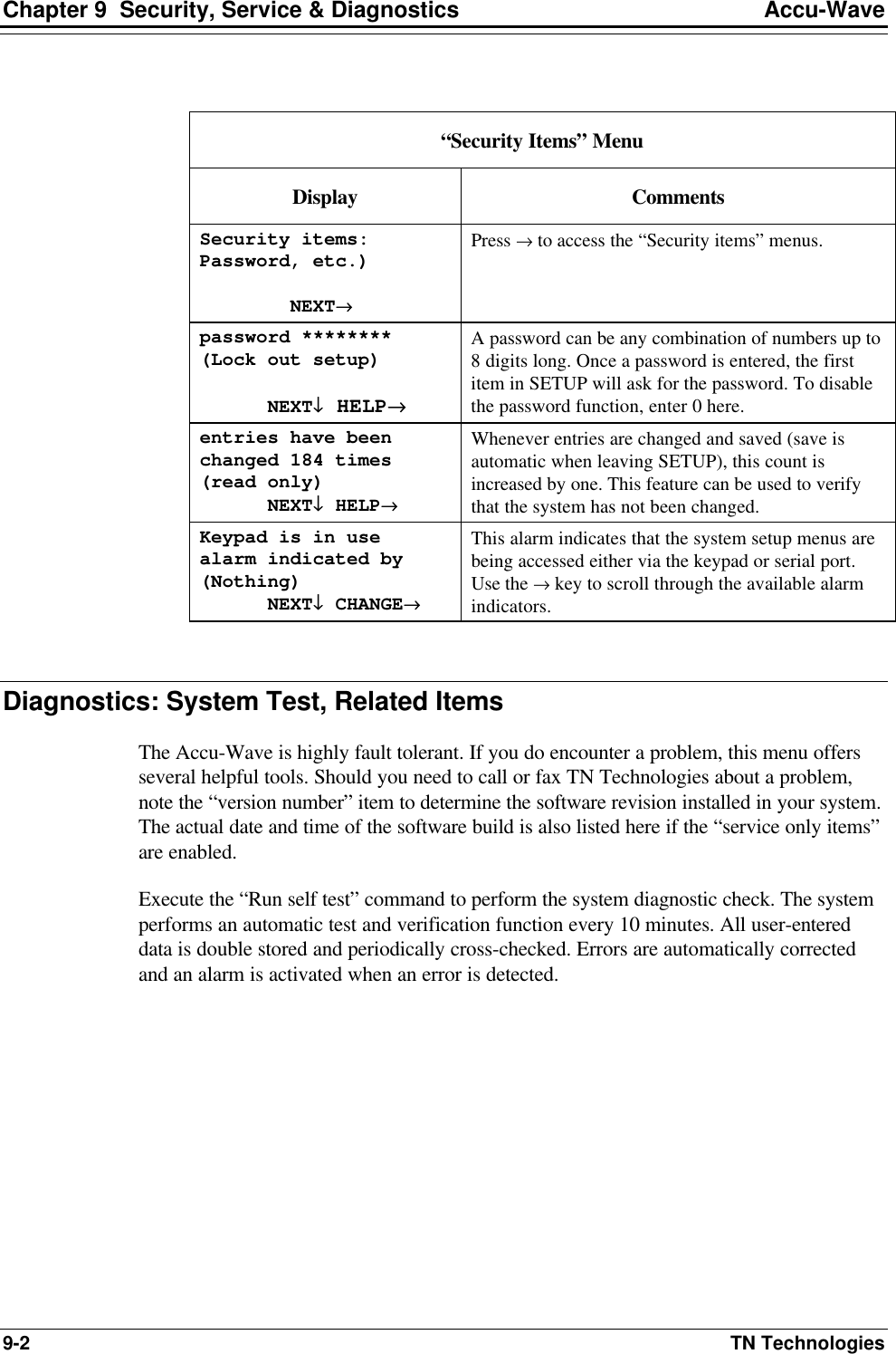
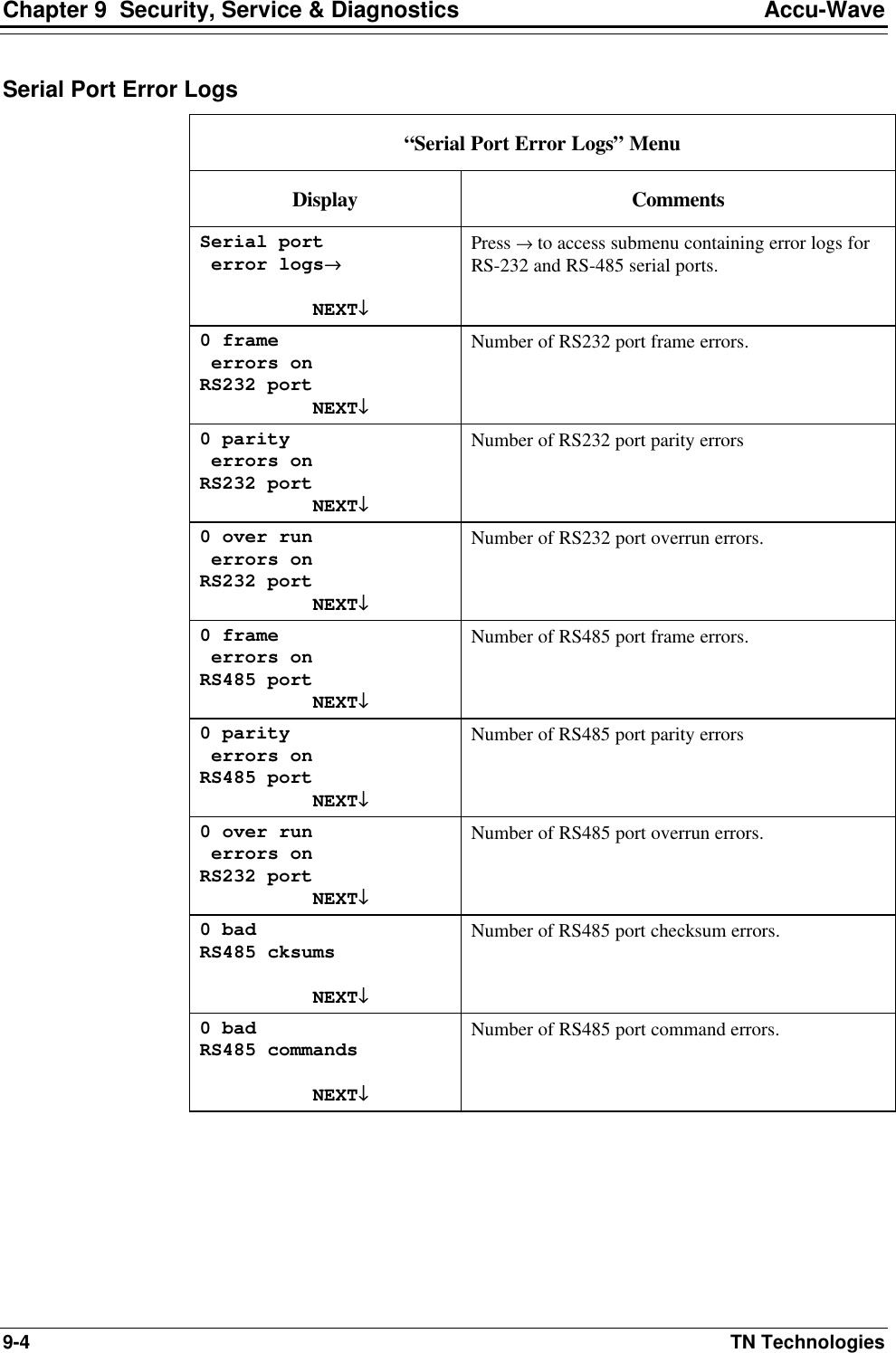
![Accu-Wave Chapter 9 Security, Service & Diagnostic TN Technologies 9-3 “Diagnostics: System test, related items” Menu Display Comments Diagnostics: System test, related items→→ NEXT↓↓ Press → to access the “Diagnostic…” menu items. Run self test ←←Exit this menu. NEXT↓↓ EXECUTE CMD→→ Execute the self-test command to test the various types of memory, the data integrity, and the signal processor. View alarm status→→ NEXT↓↓ View any alarms resulting from self-test as well as other alarms presently in effect, including process, warning, fault, and mode alarms. View alarm history→→ NEXT↓↓ Review all alarms which have occurred since the last clear alarms command, including process, warning, fault, and mode alarms. Serial port error logs→→ NEXT↓↓ Sub menu containing error logs for RS-232 and RS-485 serial ports. See “Serial port error logs” table below. relay history logs→→ NEXT↓↓ Only displayed if relays are installed. Submenu containing logs of relay activity including cumulative on time and number of times activated. See “relay history logs” table below. Program rev # 4.31 NEXT↓↓ Software version number. Note this number when calling TN Service with questions. Program rev # 4.31 11-MAY-1998 05:33:21 NEXT↓↓ [ Service only item] Software version number and date/time of software build. Note this number when calling TN Service with questions. Snapshot MENU→→ NEXT↓↓ [ Service only item] Show instantaneous value of various dynamic internal parameters. See the “Snapshot” menu table below. View internal constants→→ NEXT↓↓ [ Service only item] Submenu to display values of various internal constants that are computed based on user entries.](https://usermanual.wiki/Thermo-MeasureTech/1440-15.Operating-Manual-for-1440/User-Guide-91777-Page-117.png)
![Accu-Wave Chapter 9 Security, Service & Diagnostic TN Technologies 9-5 Relay History Logs “Relay History Logs” Menu Display Comments relay history logs→→ NEXT↓↓ Only displayed if relays are installed. Press → to access non-volatile logs (saved every hour) of relay activity. Relay 1 on time 142.1 hours (non-volatile save once per hour) NEXT↓↓ Cumulative total of “on” time (need not be continuous) for relay 1. This menu item is repeated for each relay installed. Relay 1 has been on 25 times. (non-volatile save once per hour) NEXT↓↓ Cumulative number of times relay 1 has been turned on (since last time memory was cleared). This menu item is repeated for each relay installed. Snapshot Menu “Snapshot” Menu [Service only item] Display Comments Snapshot MENU→→ NEXT↓↓ [ Service only item] Press → to view instantaneous value of various dynamic internal parameters. Note: The next menu item is repeated for each measurement which has been setup using the “Set up additional measurements” menu. readout from measurement 1 11.07 ft level ←←CONT UPDATE→→ NEXT↓↓ Provides snapshot of measurement 1 readout. Press → to update display. Press ← to switch to continuous update mode. Display will then show ←FREEZE. Pressing ← again will switch back to “freeze” or snapashot mode. This has no effect on the measurement display. readout from measurement 2 150.8 cu ft ←←CONT UPDATE→→ Displays the present reading from measurement 2, if measurement 2 has been set up.](https://usermanual.wiki/Thermo-MeasureTech/1440-15.Operating-Manual-for-1440/User-Guide-91777-Page-119.png)
![Accu-Wave Chapter 9 Security, Service & Diagnostic TN Technologies 9-7 “Snapshot” Menu (cont.) [Service only item] Display Comments base signal strength 113.9 NEXT↓↓ Signal Strength of “best” candidate echo as reported in the echo report. weighted signal strengh 113.9 NEXT↓↓ Signal strength of “best” candidate echo after weighting factors have been applied. View echos being processed→→ NEXT↓↓ Allows you to examine the echo report for each echo within the range of interest. Press → to access the echo reports, then press ↓ to scroll through the echo reports. The echo report is described on page 5-11. View marker report→→ NEXT↓↓ Reports relative control levels at which RF frequency markers occur. See “View Marker Report” menu table below. DSP restart count 0 NEXT↓↓ Internal value of Sensor signal 1.871E4 ←←CONT UPDATE→→ NEXT↓↓ Filtered value of echo position after electrical offset is subtracted. Press ← for continuous measurement updates. Press ← again to return to FREEZE mode. Internal value of distance 441.0 cm ←←CONT UPDATE→→ Filtered value of echo position (distance) converted to centimeters. Most internal values in the software are stored in CGS units (centimeters, grams, seconds). Note: The next three menu items will only display meaningful values when a single current output board is installed. Internal value of I out % 60.80 % ←←CONT UPDATE→→ Internal value of current output - % of range. Internal value of I out flt 5429 (8000=100%) ←←CONT UPDATE→→ Internal value of I out fix 5428 (8000=100%) UPDATE→→ This is the value actually sent to the current output board.](https://usermanual.wiki/Thermo-MeasureTech/1440-15.Operating-Manual-for-1440/User-Guide-91777-Page-121.png)
![Chapter 9 Security, Service & Diagnostics Accu-Wave 9-8 TN Technologies View marker report Before viewing any of the marker report items with direct entry, you must enter command 13 to tell the system to prepare the data. “View Marker Report” Menu [Service only item] Display Comments View marker report→→ NEXT↓↓ Submenu of “Snapshot” Submenu. Reports relative control levels at which RF frequency markers occur. Sweep drive range = 2031 (-32.60 to 1999) NEXT↓↓ MARKER #0= -32.60 delta to #1 = 104.9 slope delta=98.85% %NonLIN=0.000 The marker values are relative figures which are proportional to the sweep drive voltage at the indicated frequency marker. MARKER #1 = 72.20 delta to #2 = 208.4 slope delta =-2.591% %NonLIN=2.592 delta = difference between two markers values. slope delta = percent change in slope between one pair of markers and the next. NonLin% = percent difference between the delta of this marker pair and the average delta over the sweep. MARKER #2 = 280.6 delta to #3 = 203.0 slope delta =-1.923% NonLIN = .9292 MARKERS #3-10 – above menu items repeated for markers 3-10. marker #11 = 1999 delta to #12 = 0.000 slope delta = 0.000% %NonLIN=0.000 Marker #11 is dummy marker covering only part of a frequency sub-range. Thus, the slope delta and %NonLin data relating to this point is not useful.](https://usermanual.wiki/Thermo-MeasureTech/1440-15.Operating-Manual-for-1440/User-Guide-91777-Page-122.png)
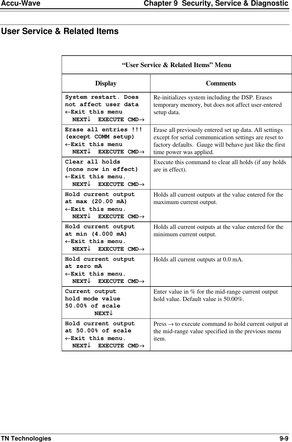
![Chapter 9 Security, Service & Diagnostics Accu-Wave 9-10 TN Technologies “User Service & Related Items” Menu (cont.) Display Comments Level hold mode value 15.00 ft level NEXT↓↓ Enter the hold value for the primary measurement (level or distance). This value is also used as the “lost echo value” when “go to hold value” is selected as the “echo loss mode.” See page 5-8. Hold level at 15.00 ft level ←←Exit this menu. NEXT↓↓ EXECUTE CMD→→ Press → to hold primary measurement value at the hold value specified in the previous menu item. After executing command, display changes to read “Clear holds→.” Press → to clear the hold level command. level hold value 0.000 cm {for abs level test} {cmd 154} NEXT↓↓ [Service only item] Enter hold value for level used to test the absolute level. Execute level hold using the next menu item. hold level at 0.000 cm ←←Exit this menu. NEXT↓↓ EXECUTE CMD→→ [Service only item] Press → to execute command to hold primary measurement value at the value specified in previous item. Use “Clear all holds” to clear. Volume hold mode value 150.0 cu ft NEXT↓↓ Only displayed if “tank volume” setup has been completed. Enter the volume hold value. Hold Volume at 150.0 cu ft ←←Exit this menu. NEXT↓↓ EXECUTE CMD→→ Press → to execute command to hold volume measurement value at the hold value specified in the previous menu item. Review measurement assignments 1-8→→ NEXT↓↓ Press → to view current measurements, e.g., Meas #s 1, 2, & 3 Level volume cu ft (inactive) → Press → to view other measurements if setup. Do enable service only items. Change to “Do”→→ Continue as is.↓↓ Change to “Do not” to disable “service only items.” This will disable a variety of additional menu items throughout the Setup menus. In particular, several of the Radar Fine Tuning tools will be disabled including “Tank Map Setup,” Region Weighting Setup,” and the “Dynamic Threshold Setup.”](https://usermanual.wiki/Thermo-MeasureTech/1440-15.Operating-Manual-for-1440/User-Guide-91777-Page-124.png)
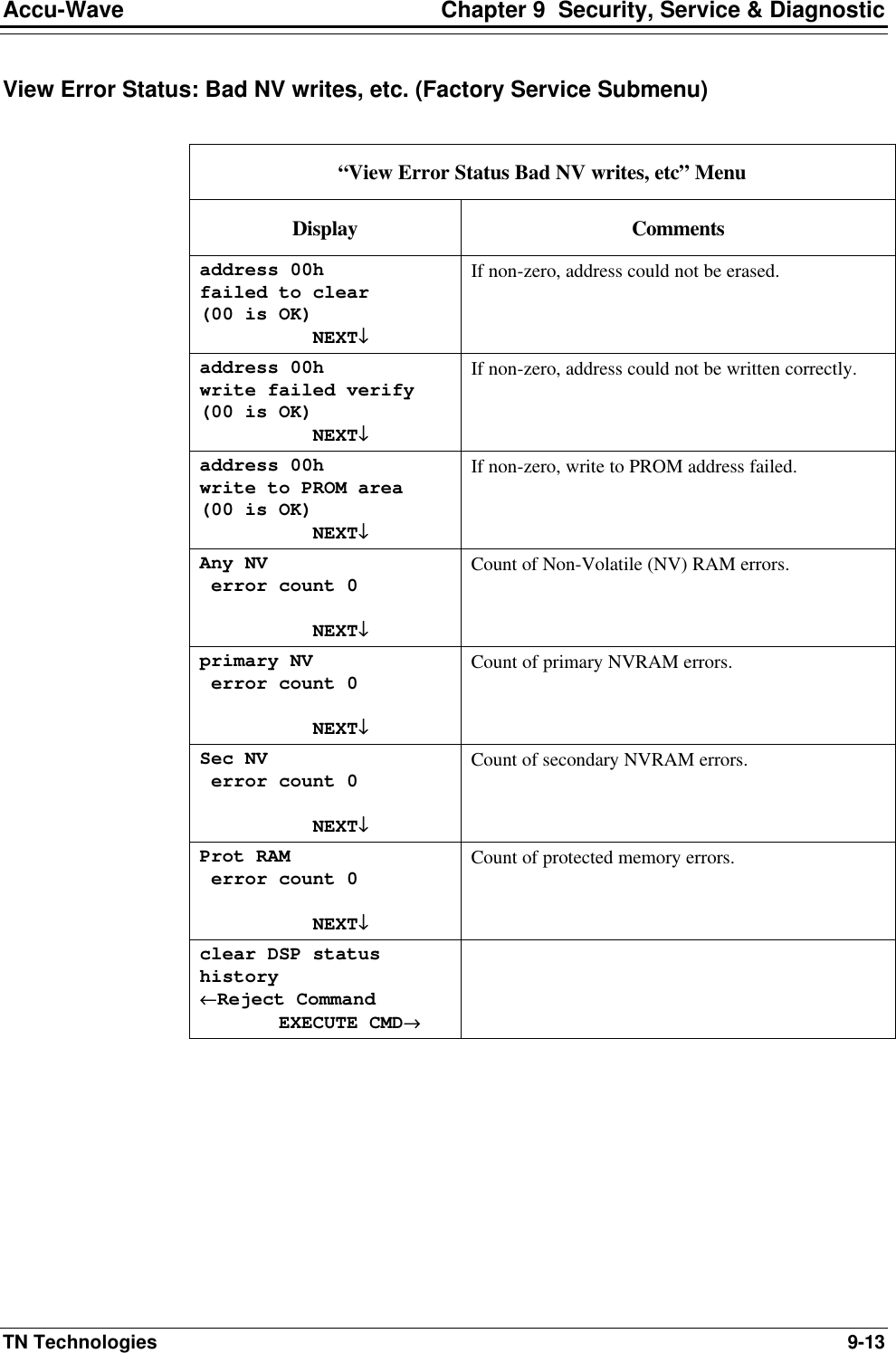
![Accu-Wave Chapter 9 Security, Service & Diagnostic TN Technologies 9-11 Factory Service & Related Items Factory Service & Related Items” Menu [Service only item] Display Comments Program rev # 4.31 11-May-1998 05:33:21 The program revision number and the date/time of the software build. DSP version: REV3.0 13:50:30 18/MAY/96 Before viewing the DSP rev # with direct entry, you must do a command 130 to tell the system to get the data. hardware diagnostics→→ NEXT↓↓ Menu subgroup header. See “Hardware diagnostics” menu table below. View error status: Bad NV writes, etc.→→ NEXT↓↓ Menu subgroup header. See “View error status” menu table below. test relays→→ NEXT↓↓ Menu subgroup header. See “Test Relays” menu table below. Do not enable RS232 test mode Change to “Do”→→ Continue as is.↓↓ Do not enable RS485 test mode Change to “Do”→→ Continue as is.↓↓ Do not disable bad entry testing Change to “Do”→→ Continue as is.↓↓ Do not disable radar, after restart Change to “Do”→→ Continue as is.↓↓](https://usermanual.wiki/Thermo-MeasureTech/1440-15.Operating-Manual-for-1440/User-Guide-91777-Page-125.png)
![Chapter 9 Security, Service & Diagnostics Accu-Wave 9-12 TN Technologies Factory Service & Related Items” Menu (cont.) [Service only item] Display Comments signal diagnostics→→ Menu subgroup header. See “Signal diagnostics” menu table below. Factory test !!! Erases ALL !!! ←←Reject command EXECUTE CMD→→ Performs an in-depth test of the system. Test takes several minutes to complete and erases all setup data. View menu, special measurement, alarm & command codes→→ NEXT↓↓ Allows you to scroll through a list of the codes for commands, special measurements (add offset of 1024 to measurement number), and alarms. Do not use break tab distance correction Change to “Do”→→ Continue as is.↓↓ Hardware Diagnostics (Factory Service Submenu) Display Comments hardware status: DSP BRD Indicates DSP board is installed. hardware status: relays installed Indicates relays are installed. Soc 1 board type: current-relay Board type installed in transmitter PCB slot #1. Soc 2 board type: none Board type installed in transmitter PCB slot #2. Soc 3 board type: DSP Board type installed in transmitter PCB slot #3. Soc 4 board type: none Board type installed in transmitter PCB slot #4. current outputs = 1 Number of current outputs installed. relays = 2 Number of relays installed. Switch INPUTs = 2 Number of contact closure inputs installed.](https://usermanual.wiki/Thermo-MeasureTech/1440-15.Operating-Manual-for-1440/User-Guide-91777-Page-126.png)
![Chapter 9 Security, Service & Diagnostics Accu-Wave 9-14 TN Technologies Test relays (Factory Service Submenu) Note: This submenu is not displayed if no relays are installed. “Test Relays” (Factory Service Submenu) [Service Only Item] Display Comments commands 88, 89, 153 relay to test = #1 NEXT↓↓ Enter relay number to test. test-set relay #1 ←←Exit this menu. NEXT↓↓ EXECUTE CMD→→ Test “setting” relay 1 (activate). test-clr relay #1 ←←Exit this menu. NEXT↓↓ EXECUTE CMD→→ Test clearing relay #1. test all relays on ←←Exit this menu. NEXT↓↓ EXECUTE CMD→→ Test turning all relays on. test all relays off ←←Exit this menu. NEXT↓↓ EXECUTE CMD→→ Test clearing all relays. clear all holds (none now in effect) ←←Exit this menu. NEXT↓↓ EXECUTE CMD→→ Clear any holds in effect. test step relay #1 ←←Exit this menu. NEXT↓↓ EXECUTE CMD→→ Press → to test closing each relay in sequence, beginning with relay number entered in first item of this menu. reset IOUT FPGA ←←Exit this menu. NEXT↓↓ EXECUTE CMD→→ Reset I/O board logic – does not reset relays.](https://usermanual.wiki/Thermo-MeasureTech/1440-15.Operating-Manual-for-1440/User-Guide-91777-Page-128.png)
![Accu-Wave Chapter 9 Security, Service & Diagnostic TN Technologies 9-15 Signal Diagnostics (Factory Service Submenu) “Signal Diagnostics” Menu [Service Only Item] Display Comments Do not spec to sweep sig for scope Change to “Do”→→ Continue as is.↓↓ Time shares the sweep control line to the head with the frequency spectrum for use with a scope. A low going pulse on the line is provided for scope trigger. Do not I.F. to sweep sig for scope Change to “Do”→→ Continue as is.↓↓ Time shares the sweep control line to the head with the I.F. (audio) signal date for use with a scope. A low going pulse on the line is provided for scope trigger. Set gain = 0.000 (1.0 – 40, overrides automatic value) (1.252 in use) NEXT↓↓ Normally, the preamp gain is adjusted based on the dielectric constant and the measurement range. This selection disables the range determined portion of the gain. Dielectric constant of process 0.000 (presently 80.00) NEXT↓↓ If value is 0.00, the “presently” assumed value is used. Enter a non-zero value to change default. Dielectric constant determines gain applied to microwave signal. Do not disable range-GAIN function. Change to “Do”→→ Continue as is.↓↓ gain set step 1 set=20.00 gain=1.252 NEXT↓↓ Gain is a non-linear function of gain setting. Select step number. + gain set 1 steps set=20.00 gain=1.252 ←←Reject command EXECUTE CMD→→ - gain set 1 steps set=20.00 gain=1.252 ←←Reject command EXECUTE CMD→→ track MIN & MAX on measurement 0 none NEXT↓↓ CHANGE→→ Press → to select measurement number. Selecting a non-zero measurement number will cause additional menu items to be displayed allowing you to track the min and max values of the selected measurement.](https://usermanual.wiki/Thermo-MeasureTech/1440-15.Operating-Manual-for-1440/User-Guide-91777-Page-129.png)