Thermo MeasureTech 1440-15 Model 1440 Radar Level Gauge User Manual Accu Wave Operation Manual
Thermo MeasureTech Model 1440 Radar Level Gauge Accu Wave Operation Manual
Contents
- 1. Operating Manual for 1440
- 2. Installation Manual for 1440
Operating Manual for 1440

Accu-Wave Radar Gauge
Radar-Based Continuous Level Measurement
Operation Manual
DRAFT
Part No. 717790
Accu-Wave Radar Gauge
Radar-Based Continuous Level Measurement
Operation Manual
DRAFT
Part No. 717790
Version 1.0
March 2000

Disclaimer
TN Technologies has made every effort to ensure the accuracy and completeness of this
manual. However, we cannot be responsible for errors, omissions or any loss of data as a
result of errors or omissions. TN Technologies reserves the right to make changes to the
manual or improvements to the product at any time without notice.
The material in this manual is proprietary and cannot be reproduced in any form without
express written consent from TN Technologies.
Refer to the equipment tag shipped with your gauge to verify the certifications for
hazardous location use applicable to your gauge. Refer to the Installation and Maintenance
Manual and the Installation/Wiring Drawings for installation instructions.
Trademarks
All registered trademarks are the property of their respective companies.
© 2000 TN Technologies
TN Technologies
2555 North Interstate 35
P. O. Box 800
Round Rock, Texas 78680-0800
TN Technologies also offers a complete line of portable x-ray fluorescence analyzers.

Accu-Wave Table of Contents
TN Technologies i
Table of Contents
Chapter 1 Introduction ................................................................................................................................ 1-1
Description ..................................................................................................................................................... 1-1
Features and Benefits...................................................................................................................................... 1-3
How the Accu-Wave Works ............................................................................................................................ 1-4
How to Use This Manual................................................................................................................................. 1-5
TN Technologies’ Service Department............................................................................................................ 1-7
Chapter 2 How to Enter Data...................................................................................................................... 2-1
Display ........................................................................................................................................................... 2-1
Keypad ........................................................................................................................................................... 2-2
Saving Your Entries........................................................................................................................................ 2-3
Setup Menus................................................................................................................................................... 2-3
Advanced Methods ......................................................................................................................................... 2-3
Chapter 3 Set up Level, Level Alarms, and Volume ................................................................................... 3-1
Set up Primary Measurement (Distance or Level)............................................................................................ 3-2
How to Set up Alarms..................................................................................................................................... 3-6
How to Set up Volume .................................................................................................................................. 3-13
Chapter 4 Set up Additional Measurements................................................................................................ 4-1
Selecting Measurement Type .......................................................................................................................... 4-1
Measurement Specific Parameters and Units................................................................................................... 4-2
Measurement Display Setup............................................................................................................................ 4-6
Display Scaling............................................................................................................................................... 4-7
Set Up Alarm….............................................................................................................................................. 4-9
Chapter 5 Radar Fine Tuning...................................................................................................................... 5-1
Material Type and Measurement Head Setup .................................................................................................. 5-2
Modify Range of Measurement ....................................................................................................................... 5-4
Response Time, Lost Echo, and Agitator Reject Setup..................................................................................... 5-6
False Echo Management............................................................................................................................... 5-11
Clutter Data Management............................................................................................................................. 5-17
Tank Map Setup ........................................................................................................................................... 5-21
Region Weighting Setup ............................................................................................................................... 5-24
Dynamic Threshold Setup............................................................................................................................. 5-26
Overall echo selection process....................................................................................................................... 5-27
Chapter 6 Current Outputs, Relays, and Alarms........................................................................................ 6-1
Current Outputs.............................................................................................................................................. 6-1
Set Up Fault Alarms or Change Process Alarm Assignments .......................................................................... 6-3
Set up for Alarms to Execute Commands........................................................................................................ 6-4
Assign Alarms to Measurements..................................................................................................................... 6-5
Assign Relays to Fault, Warning and Mode Alarms........................................................................................ 6-6
Chapter 7 Action Items ................................................................................................................................ 7-1
Common Action Items.................................................................................................................................... 7-2
Alarm Action Items ........................................................................................................................................ 7-3
Hold Action Items........................................................................................................................................... 7-4

Table of Contents Accu-Wave
ii TN Technologies
Serial Port Related Action Items ..................................................................................................................... 7-6
Chapter 8 Serial Ports, Contact Inputs, and Special Functions................................................................ 8-7
Serial Ports ..................................................................................................................................................... 8-7
Modify Port 1 RS232 (Port 2 RS485) Configuration Menus ............................................................................ 8-8
Party–Line Communications......................................................................................................................... 8-15
Contact Inputs .............................................................................................................................................. 8-18
Special Functions.......................................................................................................................................... 8-19
Chapter 9 Security, Service, and Diagnostics.............................................................................................. 9-1
Security .......................................................................................................................................................... 9-1
Diagnostics: System Test, Related Items ......................................................................................................... 9-2
User Service & Related Items.......................................................................................................................... 9-9
Factory Service & Related Items ................................................................................................................... 9-11
Appendix A How to Return Equipment for Service...................................................................................... A-1
Appendix B Specifications ............................................................................................................................. B-1
Appendix C Menu Flowcharts ....................................................................................................................... C-1
Glossary 1

Accu-Wave Chapter 1 Introduction
TN Technologies 1-1
Chapter 1 Introduction
The Accu-Wave Model 1440 Radar Level Gauge uses a microwave signal to continuously
measure the level of the process material. The Accu-Wave can often provide better
performance than sonic measurement systems, particularly in hostile environments,
because the microwave signal is unaffected by mist, surface agitation, temperature
changes, or pressure changes. The menu-driven user interface, with built–in help screens,
is designed to make the gauge easy to set up and operate.
The Accu-Wave transmits a microwave signal that is reflected from the surface of the
process material. The reflected signal or echo is received by the Accu-Wave. The Digital
Signal Processing (DSP) software detects the echo and computes the distance to the liquid
or solid material in the tank. The Accu-Wave firmware uses the distance measurement to
calculate level, volume, and other user-selected measurements.
Description
The Accu-Wave Radar Level gauge consists of an integrated sensor and transmitter with
the microwave sensor and transmitter circuitry combined on a single electronics board. The
microwave signal is launched from the bottom of the board via the cup/probe assembly
into the antenna (or probe). The antenna serves to focus the transmitted signal as well as to
receive the reflected echo. Currently, the Accu-Wave is available with dielectric rod
antennas (probes). Horn antennas will be available as a future option.
Antennas
The standard antenna configuration for the Accu-Wave gauge consists of a dielectric-
filled, 1 inch O.D. stainless steel waveguide with a dielectric rod antenna. The dielectric
rod antenna is available in either polypropylene or Teflon (PTFE). The stainless steel (SS
316) waveguide material is swaged (crimped) over the dielectric-fill material. The swage
serves both as a process seal as well as a pressure seal. The PTFE antenna design also
uses o-rings to ensure the integrity of the process seal at low temperatures. Both Viton and
Kalrez o-rings are available.
Horn antennas will be as a future option, with diameters ranging from 2 to 8 inches.
Mounting Configurations
The dielectric rod antennas are fitted with a 1-inch NPT threaded bushing, welded to the
waveguide. Welded flanges are also available – 150 lb. or 300 lb., with diameters ranging
from 2 to 8 inches. Waveguides are available in 6, 9, 12, or 15 inch lengths, where the
length refers to the portion of the waveguide that extends below the bushing or the flange.
For optimum performance the end of the waveguide should reach to the bottom of the
nozzle.
Level measurements can be continue to be made as the level of the process material rise
above the bottom of the antenna to within ~3.5 inches of the bottom of the waveguide.

Chapter 1 Introduction Accu-Wave
1-2 TN Technologies
Measurement accuracy, however, is degraded when the process level is above the bottom
of the probe.
Approvals
The Accu-Wave has been certified for use in hazardous locations as follows (approvals are
pending as of 1 March 2000):
FM
• Class I, II, III, Division 1, Groups B, C, D, E, F, G
• Class I, II, III, Division 2, Groups B, C, D, F, G
• NEMA 4X
CSA
• Class I, II, III, Division 1, Groups B, C, D, E, F, G
• Class I, II, III, Division 2, Groups B, C, D, E, F, G
• TYPE 4X
CENELEC
• EEx d IIB + H2
• Eex n IIB + H2
See Appendix C for additional information regarding specifications and safety approvals.
Note: Verification of chemical compatibility with the exposed antenna materials
is ultimately the responsibility of the customer.
Sensor-Transmitter
The sensor and transmitter are integrated on the single electronics board. The transmitter
detects the signal reflected from the process material. The detected echo is used to measure
the distance to the process material and to calculate other measurement values. These
values can be displayed, sent to the serial ports (RS-485 standard, RS-232 optional), and
can be used to drive the current output or process alarms.
The RS-485 and optional RS-232 serial ports support communications from a PC with the
Accu-Wave Window’s based Setup Software, a PC with terminal emulation software, or a
TN Technologies' Hand Held Terminal a remote terminal.
The Accu-Wave supports 4-20 mA current output, serial communications, contact closure
input, and a 2-line local/remote display. The Accu-Wave inputs and outputs are
summarized in the following Input/Output Characteristics Table.
Accu-Wave Chapter 1 Introduction
TN Technologies 1-3
Input/Output Characteristics
Type Characteristics Comments
Current output 0-20 mA dc (adjustable range)
Isolated, Loop-Powered,
24 Vdc Nominal Supply
Voltage, 700 ohm max. load
Default range is 4-20 mA dc.
One current output is provided.
Serial
communications
RS485: One terminal block and
one RJ11 Jack
RS 232: One terminal block
(Requires optional board.)
Half-duplex party line
communication to host computer
or Hand-Held Terminal.
Full duplex communication with
a remote terminal or PC.
Contact closure
input
One (1) contact closure input is
provided. The user can assign a command
to execute based on user-provided
contact opening or closure input
to the gauge.
Remote Display 2 Line x 16 Character Display
- Backlit
Features and Benefits
Dynamic Menu System
You see only the menu options pertinent to your application. The initial “Set up level, ...”
menu takes you through a basic setup to get your instrument up and running quickly. Help
screens are available at appropriate points.
Built-in Volume Measurement
Select one of the pre-defined tank shapes, enter its dimensions, and the gauge computes
volume from an internal equation library. Alternately, you can define volume as a
polynomial expression based on the level (height) or as a break table of volume and height
value pairs.
Instantaneous Response
TN Technologies Dynamic Process TrackingTM (DPT) ensures no lag time in the system
response to level changes. When sudden process changes occur, the DPT feature reduces
the normal averaging time constant by a factor of eight, ensuring a smooth and rapid
output response. When the process stabilizes, the longer time constant is applied to reduce
spurious fluctuations in the measurement. In this way, actual changes in process level are
immediately reflected in the transmitter output, while the effects of signal variations from
turbulence and other short term factors on the measurement are greatly reduced.

Chapter 1 Introduction Accu-Wave
1-4 TN Technologies
Extensive Alarms
You can set up as many as 16 process alarms in addition to system fault alarms and
warning alarms.
Quick and Easy Setup
The menus take you through the setup procedure step–by–step. Built-in help screens are
provided at appropriate points in the menu structure.
Multiple Readouts
You can select up to six of the following values for display: level, distance, volume,
unfilled volume, percent full, percent empty, percent distance, percent level, signal
strength, or alarm relay status. The screen automatically displays the measurement values
three at a time in alternation. The measurement values can also be sent to a remote
terminal or a computer.
Marker Sweep Software
TN Technologies’ patented Marker Sweep software continually adjusts the transmitter
output signal to maintain linearity. This highly consistent microwave signal ensures
reliable, stable system operation and accurate level measurements.
Digital Signal Processing (DSP)
The gauge uses DSP hardware and software to process the received microwave signal (the
echo) and to provide accurate, real-time measurements of the distance to the surface of the
process material.
How the Accu-Wave Works
The sensor generates a microwave signal composed of electromagnetic waves – two
perpendicular oscillating fields (electric and magnetic) that travel together. The transmitted
signal is reflected from the surface of the process material. This echo is detected and
evaluated for changes in frequency to determine the distance to the liquid or solid material
in the tank.
The Marker Sweep software continually adjusts the signal output to maintain the linearity
of the transmitted frequency sweep. This highly consistent microwave signal ensures that
changes in level are reported accurately in real-time. Dynamic Process Tracking software
ensures quick system response to changing process levels by automatically reducing the
response time when level changes occur. A variety of tools are provided in the menus to
“fine tune” the signal in order to eliminate many of the problems associated with
measuring levels in an active process.
TN’s exclusive DSP software processes the microwave signal and converts it to
measurement information displayed in the readout. You can also program measurements to

Accu-Wave Chapter 1 Introduction
TN Technologies 1-5
drive alarms, or open and close switches. The alarms, user inputs, and selected outputs are
saved in non-volatile memory.
Automatic verification and error correction software continuously monitors system
operations. System faults can be programmed to set off alarms.
How to Use This Manual
For hardware mounting and installation wiring procedures refer to the “Accu-Wave
Installation Manual” provided with your gauge.
This manual, “Accu-Wave Operation Manual” describes how to set up and operate the
Accu-Wave gauge. Chapter 1, “Introduction,” provides an overview of the Accu-Wave
gauge and its features.
Note: This manual describes Version 4.31 of the Accu-Wave software. Earlier
versions of the software do not support all of the tools and functions
described in this manual.
We suggest that you read the appropriate chapters before you begin to set up your gauge.
Setting Up the Gauge
Chapter 2, “How to Enter Data,” introduces the menu system and how to enter or modify
the setup parameter values. The menu items are grouped into seven top level categories as
described below. Chapters 3 through 9 provide detailed information on the menu items in
each of these seven categories. For many applications, only the “Set up Level, Level
Alarms, and Volume” menu items are required to set up the Accu-Wave gauge.
Chapter 3, “Set up Level, Level Alarms, and Volume,” explains how to set up the primary
measurement (distance or level), measurement alarms, and the volume measurement
(optional).
Chapter 4, “Set up Additional Measurements,” explains how to set up the following
additional measurements:
− distance (outage), if the primary measurement is level
− level, if the primary measurement is distance
− percent distance
− percent level
− signal strength
− volume
− unfilled volume (ullage)
− percent full
− percent empty

Chapter 1 Introduction Accu-Wave
1-6 TN Technologies
Chapter 5, “Radar Fine Tuning,” explains the “Radar fine tuning” menu. Use this menu to
adjust the setup when false echoes and clutter are present, or to extend the measurement
range beyond the zero level point or above the maximum level point.
Chapter 6, “Current Outputs, Relays, and Alarms,” explains how to set up the current
outputs and relays, and how to assign alarms to measurements other than the primary
measurement using the “Outputs, relays and alarms” menus.
Chapter 7, “Action Items,” describes the serial ports and describes the frequently used
commands in the “Action Items” menu. The commands are grouped by function:
− common action items
− alarm commands
− hold commands
− serial port commands
Chapter 8, “Serial Ports, Contact Inputs, and Special Functions,” describes the serial ports
and how to communicate with the gauge via a personal computer (PC).
Chapter 9, “Security, Service, and Diagnostics,” contains security, diagnostic, and service
information.
Additional Information
Appendix A, “How to Return Equipment for Service,” gives you shipping information for
returning equipment to TN Technologies for service.
Appendix B, “Specifications,” contains the specifications for the Accu-Wave.
Appendix C, “Menu Flowcharts,” provides a flowchart of the main menus.

Accu-Wave Chapter 1 Introduction
TN Technologies 1-7
TN Technologies’ Service Department
The TN Technical Services Department is available to help you, especially with the more
complicated procedures such as eliminating spurious echoes. Call us with questions or
comments:
Phone: (800) 736–0801 (US only)
Main Office: (512) 388–9100
FAX: (512) 388-9200

Accu-Wave Chapter 2 How to Enter Data
TN Technologies 2-1
Chapter 2 How to Enter Data
Several methods of entering data are available. You can scroll through the menus to reach
the menu item you want, or you can use the direct entry code to access the desired menu
item in a single step. For some data entry menu items you use the arrow keys to select
from a list, while for other data entry items you enter numbers with the keypad.
RS-232 and RS-485 serial ports are provided to support communications with the gauge
via a remote terminal, a PC with terminal emulation software, or a TN Technologies' Hand
Held Terminal.
Display
Note: Allow 2 minutes after start up for the readings to stabilize.
When power is first applied, the gauge measures and displays distance and signal strength
on the measurement display as shown in Figure 2.1. The measurement display is shown
continuously, except when you are in a menu.
23.69 ft
114 sig str
For setup press →
Figure 2.1 Measurement Display
If the display is blank when you apply power to the gauge, check the following:
1. Adjust the contrast by pressing the↑ or ↓ on the keypad several times.
2. Verify the power supply at the source.
3. Disconnect all power to the transmitter, open the transmitter and verify:
− the power supply is properly seated on the main board,
− the power supply is properly connected (refer to the “Accu-Wave Installation
and Maintenance Manual”),
− the ribbon cable from the display is properly seated on the board, and
− all boards are properly seated in the chassis notches and on the main board.
4. If you still have no display, contact TN Technologies
(1-800-736-0801, US only, or 512-388-9100).
Chapter 2 How to Enter Data Accu-Wave
2-2 TN Technologies
Keypad
Located below the display, the keypad is used to scroll through menus, change selections,
enter data, and enter commands. Figure 2.2 shows the keypad layout.
7 8 9 EXIT
SETUP
4 5 6
Contrast
↑↑
1 2 3
←← →→
0 • – ↓↓
Contrast
Figure 2.2 Transmitter Keypad Layout
Moving with the Arrow Keys
Use the arrow keys, ←, →,↑and ↓, to scroll through the menus, access HELP menu items,
change selections, and execute commands. Each item in the menus will have directions for
using the appropriate arrow keys.
In most cases, the ↓ key is used to scroll through the menu items. In many cases, you can
use the ↑ key to return to the previous menu item, unless the display indicates otherwise.
Use the → key to view HELP, when available, or to change an option. Use the ← key to
return to the previous option. When the correct option is in the display, use ↓ to go to the
next item in the menu. When you reach the bottom of a menu, press ↓ to return to the top
of that menu.
Use the EXIT SETUP key at any time to save your entries and leave the menu display,
returning to the measurement display.
Entering Numbers
Use the number keys to enter data and commands. Use the period key, “•”, for the decimal
point and the dash key, “–”, for the sign for negative numbers. After keying in a number,
press ↓ to indicate the end of the number.
Decimal values may be entered in scientific notation using the period, “•”, key in place of
the “E” or exponent. For example,
To enter: 4.567E4
Press: 4.567.4

Accu-Wave Chapter 2 How to Enter Data
TN Technologies 2-3
Press ↓ to complete the entry. The number will be displayed in the usual scientific
notation, 4.567E4.
Saving Your Entries
Press the EXIT SETUP key at any time while you are using the menus to save your entries
and to return to the measurement display.
If no entries are made for five minutes, the display times out. Any entries or changes you
have made are saved and used by the Accu-Wave software, and the display returns to the
measurement display.
Setup Menus
The setup menus provide a step-by-step procedure for entering the data required to operate
the gauge. The dynamic menu system controls which menu items are displayed; only menu
selections pertinent to your application are presented. Read the HELP screens provided at
appropriate points within the menus.
In each menu item, the data value which can be entered or changed will be flashing. Enter
the requested parameters in each applicable menu item as you come to it, otherwise related
menu items that should appear later will not be displayed. For instance, to set up an alarm,
you must enter a “set point” value when that menu item appears in order to activate the
rest of the “Alarm Setup” menu. Appendix B shows a flowchart of the main menus.
Note: The appearance of the menu items as described in this manual will often
vary slightly from the actual menu item displayed on your gauge. The
appearance of many menu items (words and numbers) varies dynamically
with context and will depend on the parameter values and selections you
enter during setup.
The menu structure has two layers of menu items, the user layer (or
default layer ) which is adequate for most applications, and the service
layer which provides a number of additional, special purpose menu items.
These additional tools (service only items) can be enabled using the
“Special functions” menu as described in Chapter 8, see page 8-19.
When you are using the setup menus, if no entries are made for five minutes, the display
times out and returns to the measurement display. Any changes or entries you have made
are saved and used by the Accu-Wave software. To continue with the setup procedure, use
the arrow keys to return to your previous place in the menus.
Advanced Methods
Direct entry and programmable keys are provided primarily for diagnostics and service
operations.
Note: Most menu items display a slightly different “message” when accessed by
direct entry than the message shown in the setup menus. Direct entry

Chapter 2 How to Enter Data Accu-Wave
2-4 TN Technologies
allows access to a single menu item, you are not able to scroll to the item
which would normally appear next in the menus.
Direct Entry
In addition to the menu system, you can also access value entries, selection codes, and
commands by direct entry. Direct entry is a short cut that bypasses the menu structure.
After setup is complete, direct entry can be useful for executing often used commands,
changing certain data entry values, or performing diagnostics.
Caution should be used when using direct entry codes to enter or change parameter values.
When changing or entering a value for a given menu item, the associated values must also
be changed or input (for example, the required tank dimensions are dependent on the tank
shape selected when setting up a volume measurement). The menus provide a step-by step
process to ensure that all required parameter values are entered. When using direct entry,
the user must know which associated values must also be modified or set.
To use direct entry, you must know the item identifier, also called the keyboard code. You
can find the keyboard code for a particular menu item while using the menus as follows:
1. Scroll to the menu item of interest.
2. For all menu items except decimal number entries (floating point entries such as
0.000), simply press the period, “•”, key.
3. For decimal or floating point number entries, press the period, “•”, key followed
by the ↑ key. (The ↑ key indicates that you are not entering a decimal number,
rather you want to see the direct entry code.)
Items with 6–digit identifiers are data entry values. Items with 1, 2, or 3 digit identifiers
are commands or action items (see Chapter 7).
Example: Finding a Keyboard Code
While you are setting up the primary measurement, (as discussed in Chapter 3), when you
reach the following menu item, press the period “•” key.
Allow display of ALL
units. Change to:
Metric or English→
NEXT↓
The information screen shown below will be displayed. Since the “Allow display of
All/Metric/English units” item is not a decimal entry, it is not necessary to press the ↑
following the period “•” key.
value is 0
Item is data entry
Keyboard code 151002
{HEX = 970C} Press ↓

Accu-Wave Chapter 2 How to Enter Data
TN Technologies 2-5
Note: The HEX number is used by the serial port in the “blind computer” mode.
You must use the decimal keyboard code to use direct entry via the
keypad.
The keyboard code, 151002, is the number used for direct entry. Press ↓ to return to the
“Allow display of All/Metric/English units” menu item.
The following menu item is the first decimal (floating point) data entry item in the “Set up
level,…” menus.
Distance REF LINE to
zero level point.
0.000 ft
NEXT↓ HELP→
Since this is a floating point data entry item, it is necessary to press the period “•” key
followed by the ↑ key to see the keyboard code. In this case the keyboard code display
shows the following information.
value is 0.000
Item is data entry
Keyboard code 015003
{HEX = 0F0F} Press ↓
Example: Using Direct Entry
You set up the primary measurement and have returned to the measurement display, but
you think you entered an incorrect value for the distance from the reference line to the
maximum distance to be measured. (Refer to Chapter 3 for a description of the setup
procedure and related menu items.) Using direct entry, you can access the appropriate
menu item without having to scroll through the menus.
1. With the transmitter in the measurement display, press the EXIT SETUP key. The
following item is displayed:
Key in entry ID or
command code then ↓
Press ↑ to exit.
2. Enter the entry ID code 013003, then press the ↓ key. The following menu item
is displayed. (The actual distance shown is dependent on your gauge setup.)
REF LINE to maximum
distance to be
measured 50.00 ft

Chapter 2 How to Enter Data Accu-Wave
2-6 TN Technologies
3. If the distance shown (50.0 ft) is correct, press the EXIT SETUP key to keep the
current value and to return to the measurement display.
4. If the distance shown is not correct, enter the correct value, and press the ↓ key.
Verify the distance shown is now correct (re-enter the number if incorrect), and
then press the EXIT SETUP key. You will see a brief message, “Processing and
storing data wait” before the measurement display returns. The new distance value
will now be used by the Accu-Wave software.

Accu-Wave Chapter 3 Set up Level, Level Alarms, and Volume
TN Technologies 3-1
Chapter 3 Set up Level, Level Alarms, and Volume
When power is first applied, the Accu-Wave gauge will be configured to measure distance
with a maximum range of 112 ft (34.1 m). Until configured otherwise, the gauge
continuously measures and displays distance and signal strength, except when you are in a
menu.
Note: Allow 2 minutes after start up for the readings to stabilize.
The measurement display, shown in Figure 3.1, shows the distance to the strongest echo in
feet and the amplitude or signal strength (sig str) of the echo.
23.69 ft
114 sig str
For setup press→
Figure 3.1 Measurement Display
Press → to begin setting up the primary measurement. The gauge continuously makes
measurements, even while in the menu display. The primary measurement is distance by
default, but you can use the “Set up Level,...” menu to change to level, as described later
in this chapter.
Note: The appearance of the menu items as described in this manual will often
vary slightly from the actual menu item displayed on your gauge. The
appearance of many menu items (words and numbers) varies dynamically
with context and will depend on the parameter values and selections you
enter during setup.
Note: After you have configured the gauge and the configuration settings have
been saved, the gauge retains the configuration settings even when power
is turned off.
Typically the displayed distance will correspond to the echo from the surface of the
process material as desired, but in some cases the strongest echo will be from another
cause, such as:
− a multiple bounce from the process material and the top of the vessel. This
multiple bounce might cause a warning message, such as “signal saturated.”
− a multiple bounce from a nozzle obstruction.
− an echo from an obstruction within the vessel.
If it appears that the distance displayed on your gauge is incorrect, you can later use the
radar fine tuning tools (described in Chapter 5) to reduce the amplitude of the unwanted
echoes so that the system locks onto the correct echo. Before using these tools, you must
complete the setup for the primary measurement and define the correct range of interest, as
described in the next section.
Chapter 3 Set up Level, Level Alarms, and Volume Accu-Wave
3-2 TN Technologies
Set up Primary Measurement (Distance or Level)
During the initial setup, you will be asked to enter the distances to the highest and lowest
points on the tank that you need the gauge to “see.” Thus, you need to measure these
distances on your tank relative to the reference line marked on the sensor. Note the high
and low measurement points do not have to be the top and bottom of the tank. These points
are used to establish the range of interest (ROI) as shown in Figure 3.2. The ROI defines
the range over which the gauge looks for the echo from the process material surface. The
ROI may be overridden in the “Radar fine tuning” menu (refer to Chapter 5).
You must set up either distance or level as the primary measurement before setting up
other measurements. The Accu-Wave software numbers the measurements with
measurement #1 being the primary measurement. It is good practice to make a list of how
you set up each measurement and its measurement number, and to have this list available
for future reference.
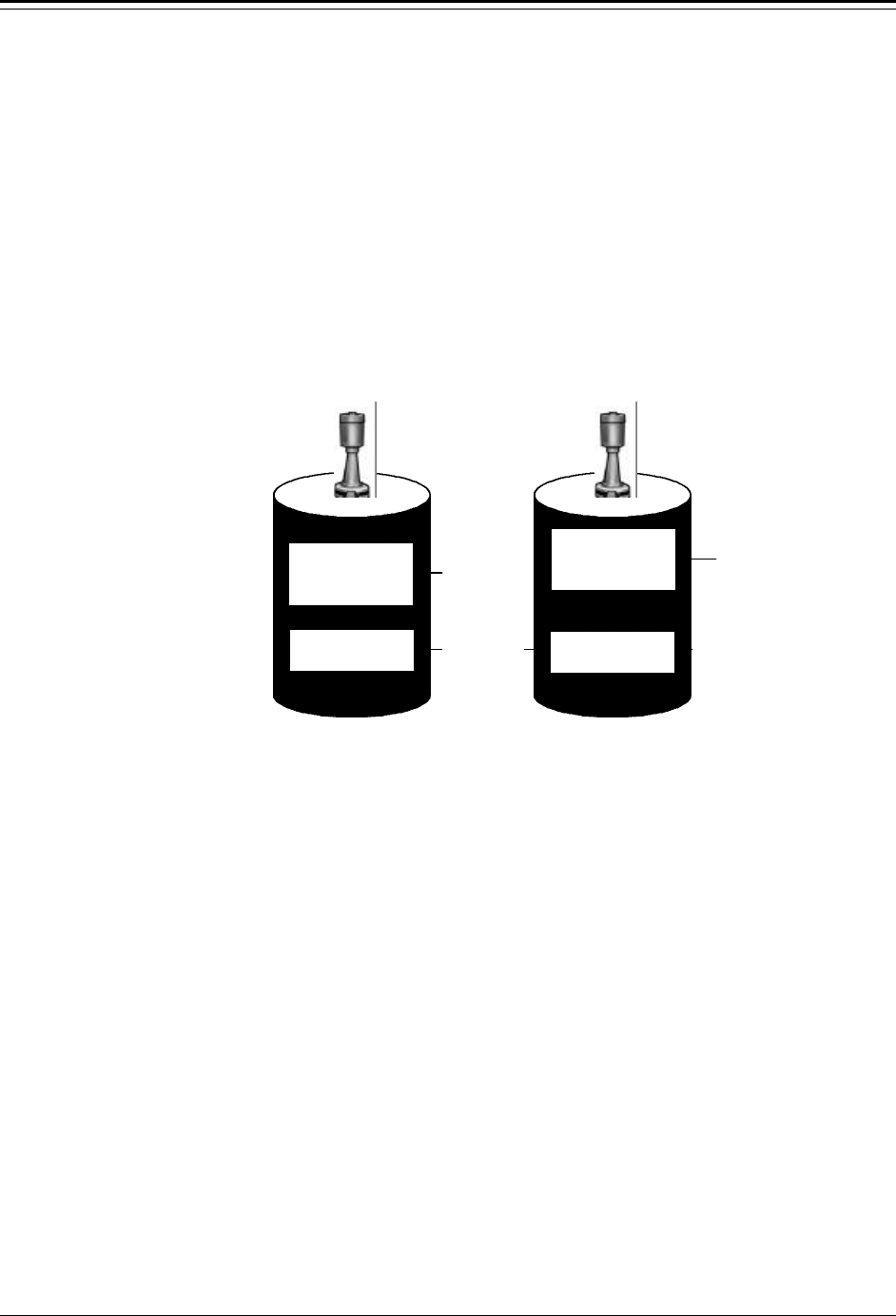
Select distance as the primary measurement if you are interested in the distance from the
zero distance point to the surface of the process material as shown on the right-hand side
of Figure 3.2. Select level as the primary measurement, if you are interested in the distance
from the zero level point to the current level of the surface of the process material as
shown on the left-hand side of Figure 3.2.
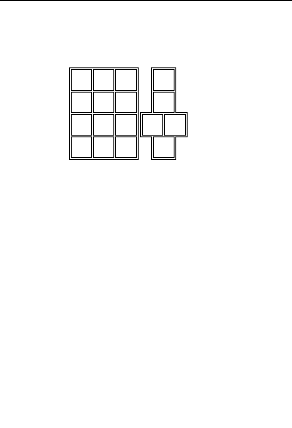
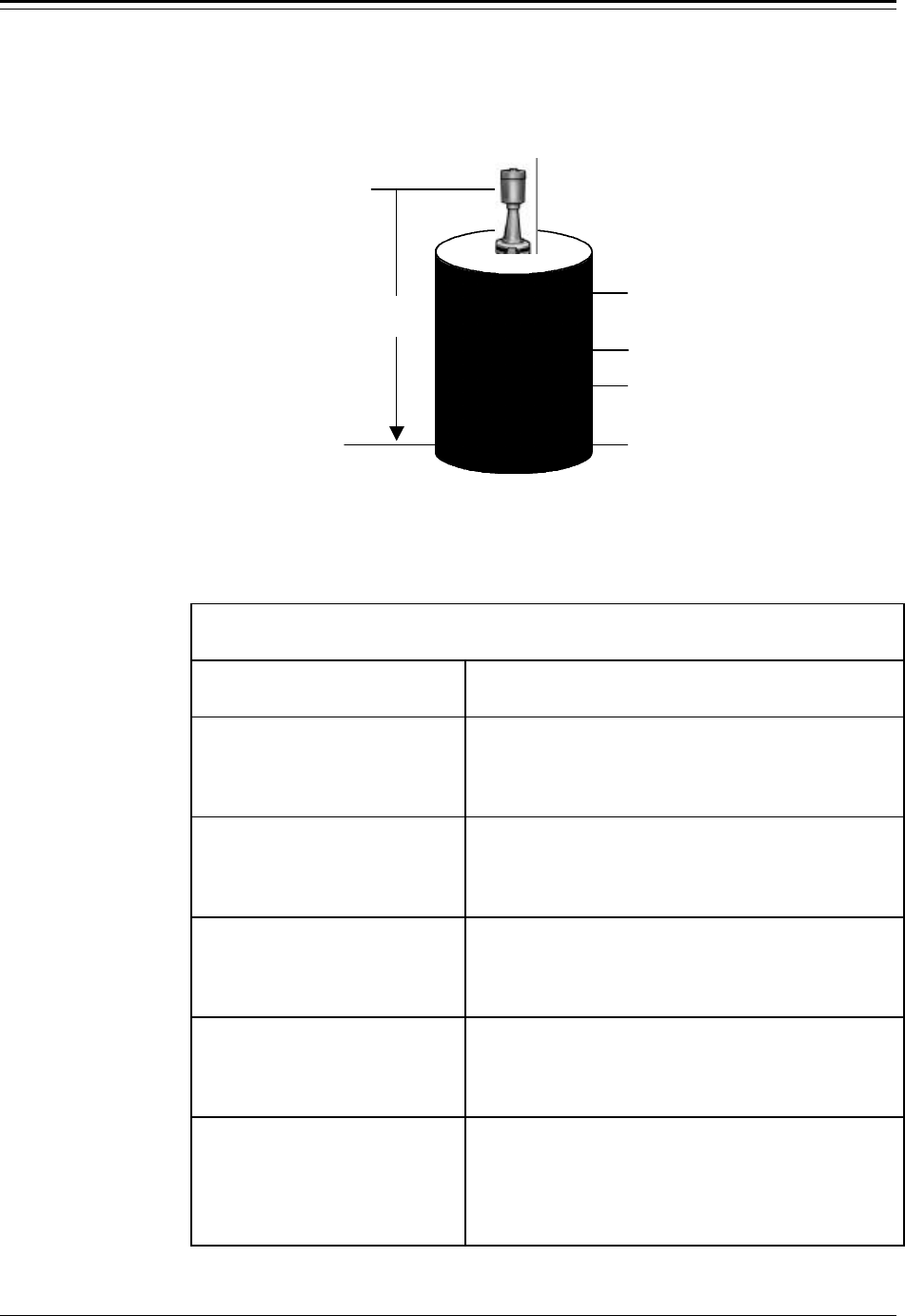
The Zero Distance, Maximum Distance, and Zero Level points are all measured from the
reference line (inscribed in the sensor housing) downward to the appropriate point on the
tank. The Maximum Level point is measured from the Zero Level point upward.
Figure 3.2 Primary Measurement – Distance or Level
After setting up the required entries for the primary measurement, you can set up
additional measurements (for example, volume, percent full and percent empty) using the
“Set Up Additional Measurements” menu discussed in Chapter 4.
“Set up Level” Menu
The “Set up Level” portion of the “Set up Level, Level Alarms, and Volume” Menu is
used to set up the primary measurement, either level or distance, for your gauge. These
menu items are given in the table below in the order they appear as you scroll through the
Reference Line
(marked on sensor)
Maximum Distance
Zero Level
Maximum Level
Range of Interest
(ROI) for level
Range of Interest
(ROI) for distance

Accu-Wave Chapter 3 Set up Level, Level Alarms, and Volume
TN Technologies 3-3
“Set up Level” menu. The “Comments” column of the table describes the purpose of each
menu item. An example showing the specific entries required to set up level as the primary
measurement is provided immediately following this table.
“Set up Level” Menu
Display Comments
Set up level, level
alarms & volume
←←Exit Setup.
Other functions→→
From the measurement display, press → to move to
the “Set up level,...” menu shown at the left. Press ↓
to access the “Set up level,…” menu items.
Note: The software detects whether output relays
are installed. If no relays are present, the
menu will display “Set up level & volume.”
General HELP text.→→
Information on how
to set up this gauge
NEXT↓↓
We strongly suggest you read the HELP screens,
especially when you are first learning to set up the
gauge. Press ↓ to proceed to the next menu item.
primary measurement:
Distance
Change to Level→→
NEXT↓↓
The primary measurement can be either distance or
level. Distance is the default.
Allow display of ALL
units. Change to
Metric or English→→
NEXT↓↓
Select the desired set of units for the primary
measurement using the → key. The default is ALL
which includes both English and Metric units.
English units are - in, ft, and yd. Metric units are -
mm, cm, and M.
Distance units = ft
To change to yd, M,
cm, mm, or in press→→
NEXT↓↓
Scroll through and select desired measurement units
using the → key. The available units depend on
previous menu item selection of ALL, English, or
Metric units.
Note: The next two menu items define the Range of Interest, the range over which
the gauge looks for the echo from the process material surface. The values
to be entered depend on whether distance or level is selected as the primary
measurement.

Chapter 3 Set up Level, Level Alarms, and Volume Accu-Wave
3-4 TN Technologies
“Set up Level” Menu (continued)
Display Comments
If the primary measurement is distance, the following two menu items are shown.
Distance REF LINE to
zero distance point
0.000 ft {.6910} MIN
NEXT↓↓ HELP→→
Enter the distance from the reference line on the
sensor housing to the zero distance point, the closest
point to the sensor to be measured. In most cases the
zero distance point is the top of the tank. The readout
will be zero at the zero distance point. Above this
point, the readout will be negative.
REF LINE to maximum
distance to be
measured 0.000 ft
NEXT↓↓ HELP→→
Enter the distance from the reference line on the
sensor housing to the maximum distance point, the
farthest point from the sensor, to be measured.
If the primary measurement is level, the following two menu items are shown.
Distance REF LINE to
zero level point
0.000 ft {115.1 MAX}
NEXT↓↓ HELP→→
Enter the distance from the reference line on the
sensor housing to the point on the tank where the
level measurement readout should display zero. The
zero level point does not have to be at the bottom of
the tank. Below the zero level point, the readout will
be negative.
Maximum level
to be measured
0.000 ft {x.xxx MAX}
NEXT↓↓ HELP→→
Enter the highest possible level to be measured
relative to the zero level point. The value displayed as
{x.xxx MAX} is calculated based on the entry for the
zero level point. The gauge will not measure reliably
above this level.
Position of decimal
in readout 1 000.0
{ft level}
NEXT↓↓ ←←CHANGE→→
Press ← or → to move decimal point to the desired
position in the display readout for the primary
measurement (level or distance).
Note: The next two menu items define the levels (or distances) corresponding to
the maximum and minimum current outputs. The default range for the
current output is 4.0 mA to 20.0 mA. To change the max or min current
output, use the “Modify or reassign current output” menu (see Chapter 6.)
Meas #1 reading for
20.00 mA output:
0.000 ft level
xx.xx assume NEXT↓↓
Enter level or distance which corresponds to the
maximum current output. For level, “Maximum
level” is the default (assumed) value. For distance, the
value (Maximum Distance – Zero Distance Point) is
the default. If the entry is exactly zero, the default
(assumed) value is used.
Meas #1 reading for
4.000 mA output:
0.000 ft level
NEXT↓↓
Enter level or distance which corresponds to the
minimum current output. The default value is 0.0. For
level, this is the “Zero Level Point,” and for distance,
this is the “Zero Distance Point.”
Accu-Wave Chapter 3 Set up Level, Level Alarms, and Volume
TN Technologies 3-5
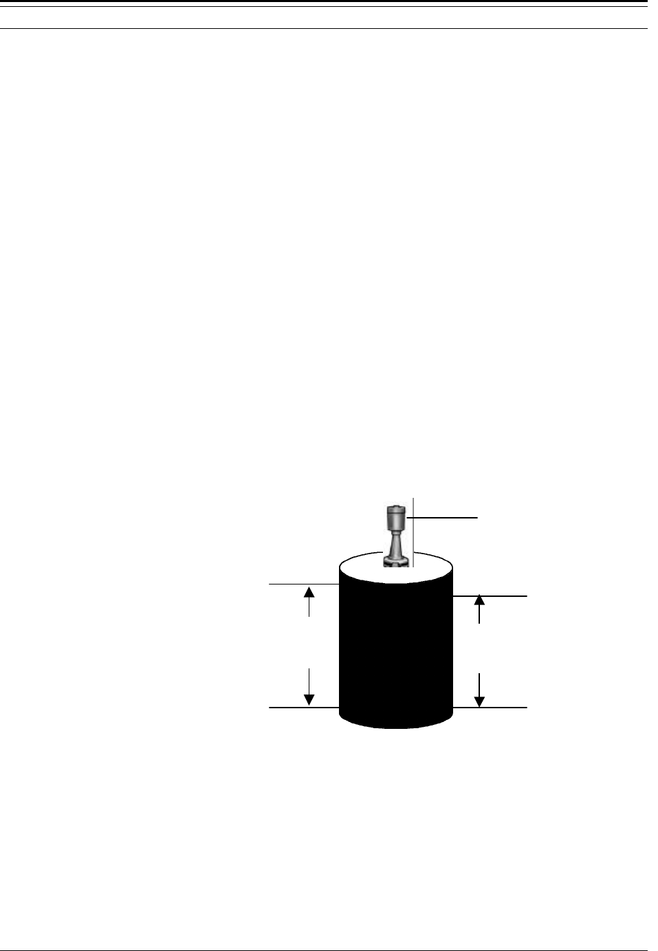
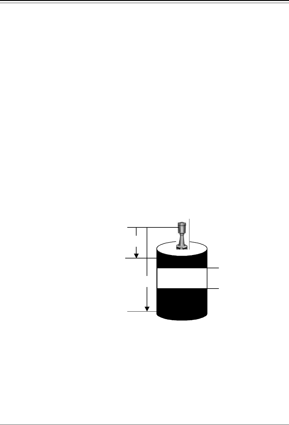
Example: Set up Level
Set up level as the primary measurement for a tank. Before beginning the gauge setup, you
need to measure the distance from the Reference Line on the sensor housing to the desired
Zero Level point on the tank and the distance from the Zero Level point to the desired
Maximum Level to be measured. See Figure 3.3.
Figure 3.3 Entries Required to Set up Level as Primary Measurement
Follow the steps in the table below to set up level as the primary measurement using the
example measurements shown in Figure 3.3.
Example: Set up Level as Primary Measurement
Menu Display User Action
Set up level, level
alarms, & volume.↓↓
←←Exit Setup.
Other functions→→
From the measurement display, press → to move to
the “Set up level,...” menu shown at the left.
Then, press ↓ to access the “Set up level,…” menu
items.
General HELP text.→→
Information on how
to set up this gauge
NEXT↓↓
General HELP text for setting up the gauge. Press →
to read the help text, press ↓ to proceed to the next
menu item.
primary measurement:
Distance
Change to Level→→
NEXT↓↓
The default primary measurement is “distance.” Press
the → key to change to “level.” Then press ↓ to
proceed to the next menu item.
Reference Line
Zero Level
Maximum Level
Zero Level
22.5 ft

Chapter 3 Set up Level, Level Alarms, and Volume Accu-Wave
3-6 TN Technologies
Example: Set up Level as Primary Measurement (cont.)
Menu Display User Action
Allow display of ALL
units. Change to
Metric or English→→
NEXT↓↓
Select the desired set of measurement units using the
→ key. The default is ALL which includes both
English and Metric units. Then press ↓.
Distance units = ft
To change to yd, M,
cm, mm, or in press→→
NEXT↓↓
Use the → key to scroll through and select the desired
measurement units. We are using “ft” in this
example.
Distance REF LINE to
zero level point
22.50 ft {115.1 MAX}
NEXT↓↓ HELP→→
Enter the distance from the reference line on the
sensor housing to the zero level point (the farthest
point from the sensor to be measured). In this
example the value is 22.5 ft. Enter 22.5 followed by
the ↓ key. Press ↓ again to move to the next item.
maximum level
to be measured.
18.00 ft (21.74 MAX)
NEXT↓↓ HELP→→
Enter the maximum level to be measured relative to
the zero level point, 18.0 ft, in this example. Enter
18.0 followed by the ↓ key. Press ↓ again to move to
the next menu item.
Position of decimal
in readout 1 00.00
{ft level}
NEXT↓↓ ←←CHANGE→→
Press ← or → to select the desired position for the
decimal point.
9.91 ft level
63 sig str
For setup, press →→
Press “Exit Setup” to save entries and return to the
measurement display.
How to Set up Alarms
After setting up distance or level as the primary measurement, the next item in the “Set up
Level,…” menu is the “Set up alarm 1” selection. These menu items allow you to set up an
alarm for measurement # 1, the primary measurement (level or distance).
Note: If no relays are installed, the “Setup alarm” menu item is not displayed.
You can still set up a display alarm that causes the appropriate line in the
display to flash off and on, or to perform some other function. Refer to
Chapter 8 for details on enabling these alternate alarms.
Alarms for measurements other than the primary measurement
(measurement 1) are set up using the “Set up Additional measurements”
menu (Chapter 4). The procedure for entering the alarm parameters is the
same as described in this section.
Accu-Wave Chapter 3 Set up Level, Level Alarms, and Volume
TN Technologies 3-7
Alarms: Set Point, Clear Point, and Dead Band
An alarm is defined with either a set point - clear point configuration, as shown in Figure
3.4, or a set point - dead band configuration, as shown in Figure 3.5.
The set point defines the measurement value, either level or distance for the primary
measurement, at which the alarm is activated. The clear point or the dead band defines the
measurement value at which the alarm is cleared (alarm ceases).
A clear point sets a fixed measurement value at which the alarm clears. The position of the
clear point is independent of the set point and remains the same even if the set point is
moved. As illustrated in Figure 3.4, changing the set point from 3.0 m to 3.5 m has no
effect on the clear point which remains at 2.0 m.
Figure 3.4 Set Point / Clear Point Alarm
A dead band defines a fixed distance between the set point and an implicit clear point. If
the set point is moved, the implicit clear point moves also, maintaining the distance from
the set point specified by the dead band. As illustrated in Figure 3.5, changing the set point
from 2 m to 3 m moves the implied clear point from 4 m to 5 m. The relative distance
between the implied clear point and the set point remains fixed at 2 m, the dead band
value.
If you may want to later change the alarm set point without affecting the point where the
alarm is cleared, use a clear point configuration. Alternately, if you want the alarm clear
point to be defined at a fixed distance relative to the set point, use a dead band
configuration.
b. Modified Set
Point /Clear Point
a. Initial Set Point
/Clear Point Alarm
3.0 m
Clear Point
New
Set Point
Clear Point
Initial
Set Point
2.0 m
3.5 m

Chapter 3 Set up Level, Level Alarms, and Volume Accu-Wave
3-8 TN Technologies
Figure 3.5 Set Point / Clear Point Alarm
High Limit and Low Limit Alarms
An alarm is activated when the measurement value reaches the specified set point. The
relative values assigned to the set point and the clear point determine whether the alarm is
a low limit alarm or a high limit alarm.
If the set point value is less than the clear point (or the dead band value is positive), the
alarm is a low limit alarm. In this case, the alarm is activated as the measurement value
decreases below the set point value. The alarm stays active until the measurement value
again increases to the clear point value.
Similarly, if the set point value is greater than the clear point (or the dead band value is
negative), the alarm is a high limit alarm. In this case, the alarm is activated when the
measurement value increases beyond the set point value. The alarm stays active until the
measurement value again decreases to the clear point value.
The terms low limit and high limit refer to the relative magnitude of the set point and the
clear point, not necessarily to a high or low level. The behavior of the alarm depends on
the measurement associated with the alarm. Thus, a low limit alarm (set point < clear
point) for a distance measurement is in fact a high level alarm. A low limit distance alarm
would be triggered when the distance to the process surface decreases below the clear point
distance and reaches the set point distance value. Since the distance between the material
surface and the sensor is decreasing the level is actually increasing. Specific examples of
high limit and low limit alarms are provided later in this chapter.
b. Modified
Set Point /
Dead Band
a. Initial Set
Point /
Dead Band
Initial Set
Point (2 m)
Implied Clear
Point (4 m)
Dead Band
(2 m)
Initial Set
Point (3 m)
Implied Clear
Point (5 m)
Dead Band
(2 m)

Accu-Wave Chapter 3 Set up Level, Level Alarms, and Volume
TN Technologies 3-9
“Set Up Alarm 1” Menu (Primary Measurement)
This table describes the menu items in the “Set up Alarm” menu group.
“Set up Alarm” Menu
Display Comments
Set up alarm 1
(Alarm point, etc.)→→
NEXT↓↓
Menu is normally available only if relays are
installed. Press → to access alarm menu or ↓ to skip
alarm set up. After alarm 1 is set up, menu to set up
alarm 2 will be available, and so on.
Note: The appearance of the following menu items depends on whether distance
or level has been selected as the primary measurement. Menu items are
shown for distance. Differences are noted in the Comments.
You must enter a set point to activate the rest of the Set up Alarm menu.
←←Exit alarm 1 setup
Alarm 1 set point
0.000 ft dist
NEXT↓↓ HELP→→
Enter the distance (or level) from the zero distance
(or zero level) point to the set point; the point at
which the alarm is activated. The zero point value
was entered during the primary measurement set up.
Alarm 1 clear based
on clr point
Chng to “dead band”→→
Continue as is.↓↓
Select a clear point or dead band configuration. A
clear point is the exact measurement value at which
the alarm is cleared. A dead band specifies the span
between the set point and the implicit clear point.
Alarm 1 clear point
0.000 ft dist
{Makes alarm “Low”
limit} NEXT↓↓ HELP→→
Enter desired clear point value: the distance (or level)
relative to the zero distance (or zero level) point. If
dead band is selected, enter the dead band span
relative to the set point. A negative dead band makes
the alarm high (set pt > clear pt. A positive dead band
makes the alarm low (set pt < clear pt).
Alarm 1: ft dist
is indicated by
controlling relay 1
NEXT↓↓ CHANGE→→
Select the action used to indicate that alarm 1 has
been triggered. The default is “controlling relay 1,” if
relays are installed. Other selections are:
controlling relay 2 (or 3 or 4 if installed)
measurement #1 display flash
measurement #2 display flash (or meas #3, #4, etc.., if
measurements have been set up)
Zero current output 1 (or 2 if installed)
Note: Additional menu items related to controlling relays are shown in following
table. Other menu items may appear depending on entries you made
elsewhere in the menus.
Set up dist alarm 2
(Alarm point, etc.)→→
NEXT↓↓
After you set up an alarm, the option to set up the
next alarm will be presented. If you don’t want to
define another alarm, scroll past this screen.

Chapter 3 Set up Level, Level Alarms, and Volume Accu-Wave
3-10 TN Technologies
The next table presents those menu items specifically related to controlling a relay as an
alarm indicator. As noted in the Comments column, several of the menu items are only
displayed if options have been enabled in the “Special functions” menu, see “Special
Functions” on page 8-19.
“Set up Alarm” Menu (continued)
Relay Indicator Related Items
Display Comments
alarm relay 1 set
delay 0 seconds
(0-255 s after
alarm) NEXT↓↓
Only displayed if “alarm relay delay times” have been
enabled in “Special functions” menu (see page 8-19).
Alarm condition must persist for the time entered for
alarm to be activated.
alarm relay 1 clear
delay 0 seconds
(0-255 s after alarm
has cleared) NEXT↓↓
Only displayed if “alarm relay delay times” have been
enabled in “Special functions” menu (see page 8-19).
Alarm clear condition must persist for the time
entered for alarm to be cleared.
Do not use latching
mode with relay 1.
Change to “Do”→→
Continue as is.↓↓
Only displayed if relay latching has been enabled in
“Special functions” menu (see see page 8-19). When
latch mode is enabled for a relay, the relay remains in
alarm state even after the actual alarm is clear. The
relay is cleared by a “Clear alarms” command (see
page 7-3) or when system has been powered off.
Relay 1 turns on
when alarm occurs.
Change to “off”→→
←←Exit alarm 1 setup.
Only displayed if a relay alarm indicator is selected as
the alarm indicator. Non-relay indicators include
zeroing current output, flashing display, or activating
commands.
After each alarm is set up, you will have the opportunity to set up another alarm, up to 16
alarms. Always keep a written record of how each alarm is set up. You can add a relay
board at any time. You can set up more alarms later using the “Set up additional
measurements” menu, see Chapter 4.
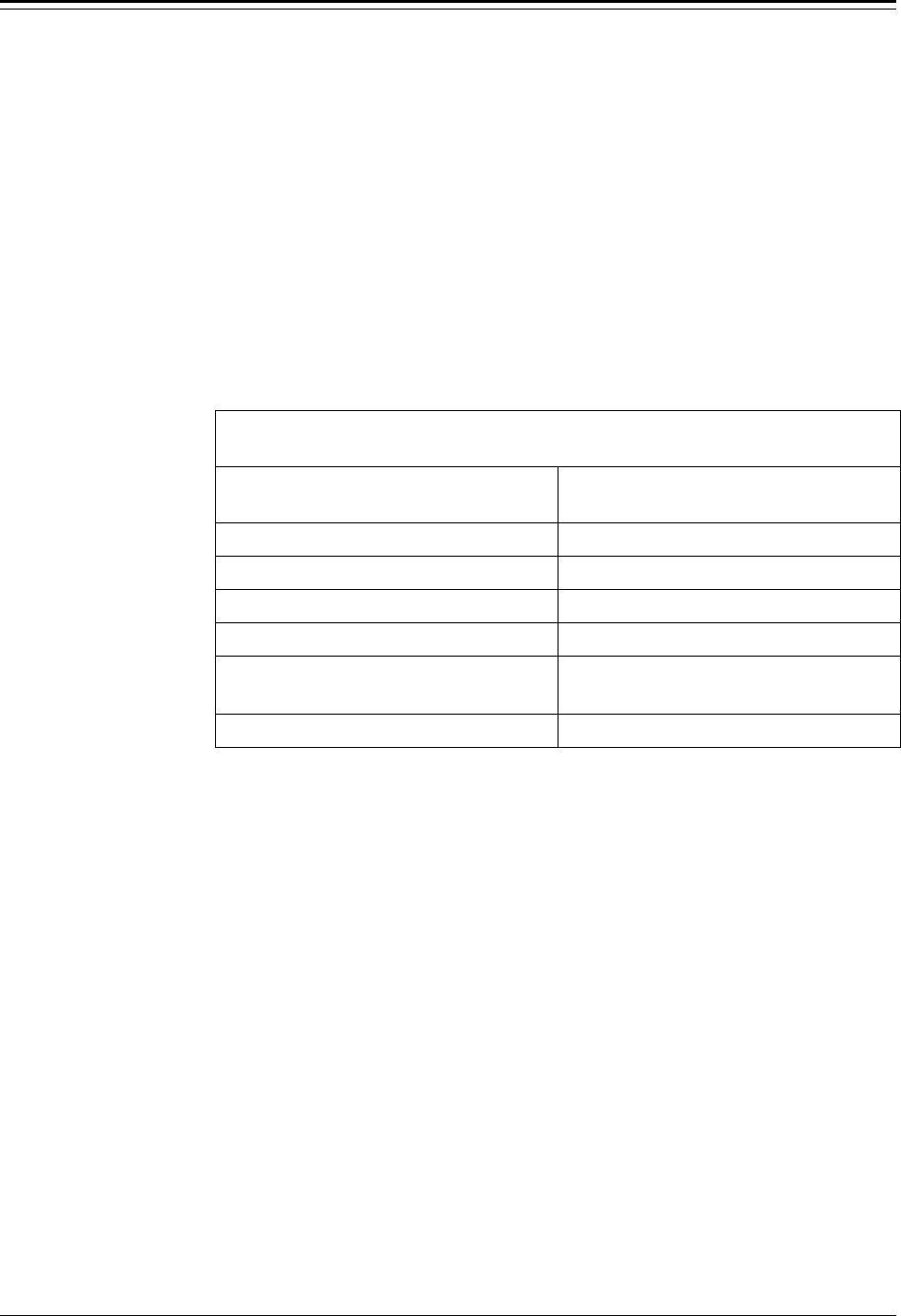
Example: High Limit Level Alarm
This example illustrates how to set up a high limit level alarm using a Set Point/Clear
Point alarm configuration. The primary measurement has been set up as level with the
“Distance REF LINE to zero level point” set at 22.5 ft and the “maximum level to be
measured” set at 18.0 ft. It is desired to activate a process alarm when the process material
level increases to 15.0 ft (relative to the zero level point) and to clear the alarm when the
process material level decreases to 13.0 ft. This configuration is illustrated in Figure 3.6.
Accu-Wave Chapter 3 Set up Level, Level Alarms, and Volume
TN Technologies 3-11
Since the measurement value for the set point (18.0 ft) is greater than the value of the clear
point (15.0 ft), this is a high limit alarm. The required steps to implement this alarm are
listed in the table following Figure 3.6.
Figure 3.6 High Limit Level Alarm Using Set Point and Clear Point
Example: Set up High Limit Level Alarm
Display Comments
Set up alarm 1
(Alarm point, etc.)→→
NEXT↓↓
Set up alarm 1 to be a high limit level alarm as
illustrated in Figure 3.6.
Press → to access the “Set up alarm” menu items.
←←Exit alarm 1 setup
Alarm 1 set point
15.00 ft level
NEXT↓↓ HELP→→
Enter 15.0 followed by ↓ to enter the desired level for
the set point relative to the zero level point. The zero
level point was entered during the primary
measurement setup. Press ↓ again to continue.
Alarm 1 clear based
on clr point
Chng to “dead band”→→
Continue as is.↓↓
Press the → to select a clear point configuration as
shown here. Then press ↓ to continue.
Alarm 1 clr point
13.00 ft level
{Makes alarm “Hi”
limit} NEXT↓↓ HELP→→
Enter 13.0 followed by ↓ to enter the desired level for
the clear point relative to the zero point level. The
display will indicte that this is a “Hi limit” alarm.
Press ↓ again to continue.
Alarm 1: ft level
is indicated by
controlling relay 1
NEXT↓↓ CHANGE→→
Select indicator for alarm 1. If relays are installed, the
default is “controlling relay 1,”. Other selections are:
controlling relay 2 (or 3 or 4 if installed)
measurement #1 display flash
Zero current output 1 (or 2 if installed)
Reference Line
Zero Level
Maximum Level - 18.0 ft
Zero Level
22.5 ft
Set Point - 15.0 ft
Clear Point - 13.0 ft
Chapter 3 Set up Level, Level Alarms, and Volume Accu-Wave
3-12 TN Technologies
Example: Low Limit Distance Alarm
This example illustrates how to set up a low limit distance alarm using a Set Point/Dead
Band alarm configuration. The primary measurement has been set up as distance with the
“Distance REF LINE to zero distance point” set to 4.5 ft and the “Distance REF LINE to
maximum distance point” set to 22.5 ft as illustrated in Figure 3.7.
It is desired to activate a process alarm when the distance of the process material surface
decreases to 3.0 ft (relative to the zero distance point) and to have the alarm clear when the
distance again increases to 5.0 ft. In addition, it is desired that the alarm clear point remain
a fixed distance from the set point if the set point value is later changed.
This is accomplished using a set point – dead band alarm configuration, with the set point
distance of 3.0 ft and with a dead band of 2.0 ft. This defines an “implicit clear point” at a
distance of 2.0 ft relative to the set point (or at a distance of 5.0 ft relative to the zero
distance point). If the set point is later changed, the implicit clear point will also change,
but will remain at a distance of 2.0 ft from the set point.
This is a low limit distance alarm since the set point distance is less than the clear point
distance. Note that this low limit distance alarm configuration is equivalent to the high
limit level alarm in the previous example. However, if the set points were changed, the
clear points would behave differently since a dead band configuration is used in this
example.
Figure 3.7 Low Limit Distance Alarm Using Set Point and Dead Band
Reference Line
Zero Distance
Maximum Distance
4.5 ft
22.5 ft
Dead Band
2.0 ft
Set Point - 3.0 ft
Implicit Clear
Point - 5.0 ft

Accu-Wave Chapter 3 Set up Level, Level Alarms, and Volume
TN Technologies 3-13
Example: Set up Low Limit Distance Alarm
Display Comments
Set up alarm 1
(Alarm point, etc.)→→
NEXT↓↓
Set up alarm 1 to be a high limit level alarm as
illustrated in Figure 3.5.
Press → to access the “Set up alarm” menu items.
←←Exit alarm 1 setup
Alarm 1 set point
3.00 ft dist
NEXT↓↓ HELP→→
Enter 3.0 followed by ↓ to enter the desired level for
the set point relative to the zero distance level. The
zero distance point was entered during setup of the
primary measurement. Press ↓ again to continue.
Alarm 1 clear based
on dead band
Chng to “clr point”→→
Continue as is.↓↓
Press → to select a dead band point configuration as
shown here. Then press ↓ to continue.
Alarm 1 dead band
2.0 ft dist
{Makes alarm “Low”
limit} NEXT↓↓ HELP→→
Enter 2.0 followed by ↓ to enter the desired level for
the clear point relative to the zero distance point. The
display indictes that this is a “Low” limit alarm. Press
↓ again to continue
Alarm 1: ft dist
is indicated by
controlling relay 1
NEXT↓↓ CHANGE→→
Select indicator for alarm 1. If relays are installed, the
default is “controlling relay 1.” Other selections are:
controlling relay 2 (or 3 or 4 if installed)
measurement #1 display flash
Zero current output 1 (or 2 if installed)
How to Set up Volume
The “Tank Volume Setup” portion of the “Set up Level, Level Alarms, and Volume” menu
defines how the gauge will calculate volume. Volume setup is optional. If you do not want
the gauge to calculate and display volume, simply scroll past the “tank volume setup”
menu.
The procedure for setting up tank volume depends on the shape of your tank. With the
“Volume setup” menu you can describe your tank by:
• selecting a tank shape from a list of pre-defined shapes,
• describing your tank as a combination of pre-defined shapes,
• setting up a “break” table for volume, a table which defines volume as a function
of the height (level of the process material) for up to 16 values of height, or
• defining volume as a polynomial (up to 6th order) expression of height.
The “Set up Volume” menu allows you to select the measurement units for reporting the
volume as well as the units for the tank dimensions. The units for the tank dimensions can
be different from the units selected for the primary measurement (level or distance).
Chapter 3 Set up Level, Level Alarms, and Volume Accu-Wave
3-14 TN Technologies
Note: Once you have set up the tank volume, volume is set as a default
measurement and is shown on the measurement display. To use volume to
drive a current output or an alarm, you must use the “Set up additional
measurements” menu (see Chapter 4) to assign volume to a specific
measurement number and to set up the parameters for the current output
or alarm.
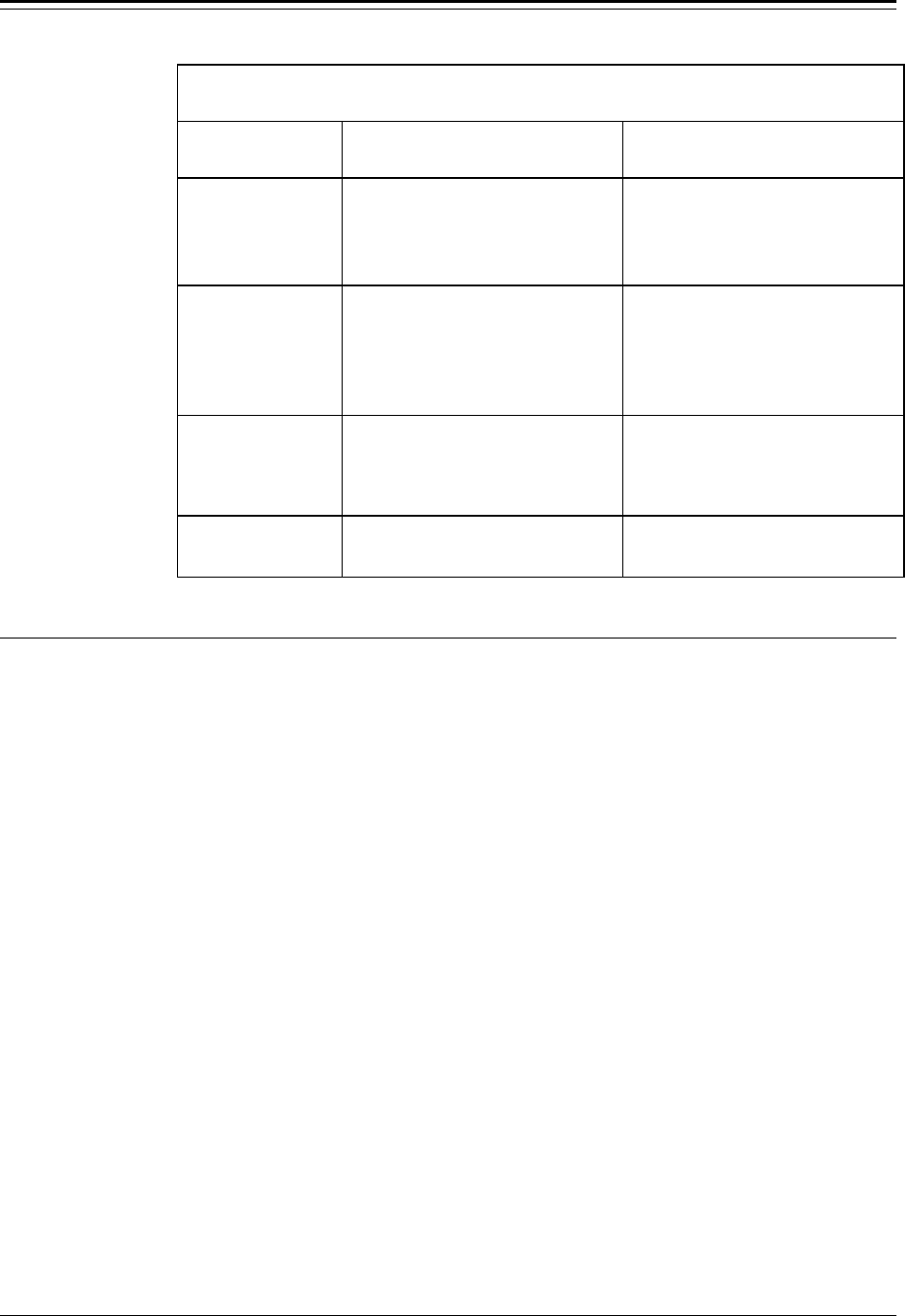
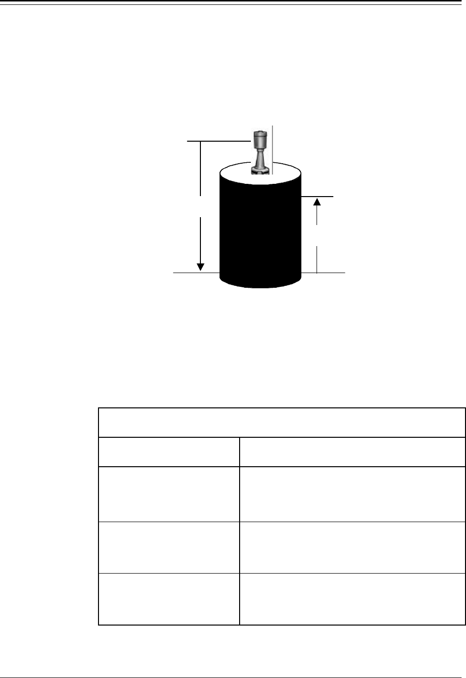
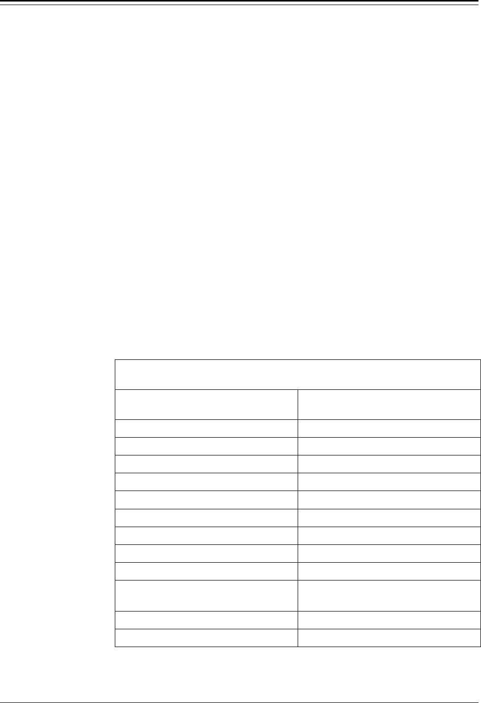
Tank Shapes
The first step in setting up the tank volume is to define the tank shape. If your tank is one
of the six shapes listed in the table below, simply select the tank shape, select the units, and
then enter the dimensions of your tank. The required dimensions depend on the selected
shape as shown in the table. The tank shapes and dimensions are illustrated in , at the end
of this chapter.
Basic Tank Shapes
Tank Shape Required Dimensions
vertical cylinder (type 1) diameter
vertical rectangle (type 2) width, length
vertical cone (type 3) top diameter, bottom diameter
horizontal cylinder/flat ends (type 11) length, diameter
horizontal cylinder/domed ends
(type 12) length (not including domed ends), total
length, diameter
sphere (type 18) diameter
Note: After you select a tank shape, the gauge will compute and display a value
for the volume. The indicated volume will be correct only if you have
entered all required dimensions.
If you did not set up level as the primary measurement, you will be asked
to enter the “Distance from the reference line to the zero-level” and the
“maximum level to be measured” in the “Set up Volume” menu.
If your tank does not fit any of these shapes, select “For other shapes or compound
shapes.” Additional menu items will be displayed allowing you to select other shapes,
define the tank as a combination of shapes, or to define volume as a table of volume vs.
height (level) data pairs, or as a polynomial expression of height.

Accu-Wave Chapter 3 Set up Level, Level Alarms, and Volume
TN Technologies 3-15
Tank Volume Units
Select the units for the volume display. Select measurement units in which to report
volume. The following units are available for volume. If you previously selected “English”
or “Metric” units for display, rather than “All,” the appropriate subset of the units listed
below will be available.
• ml milliliters or cubic centimeters
• cu Meter 1 cubic meter = 1000 liters
• cu inch 1 cubic inch = 16.39 ml
• cu foot 1 cubic foot = 28.32 liters
• cu yard 1 cubic yard = 764.6 liters
• US Gallon 3.785 liters
• UK Gallon 4.546 liters, 1.2 US liquid gallons
• Mega Gallon 1,000,000 US gallons
• Beer Gallon 4.620 liters
• liter 1 liter = 1000 milliliters
• acre foot 43560 cubic feet
• pint (US) 473.2 ml, 1/2 US quart
• quart (US) 946.3 ml, 1/4 US liquid gallon
• oz (US) 29.57 ml, 1/16 US pint
• Acre inch 3630 cubic feet
• K Gallon 1000 US liquid gallons
• UK quart 1137 ml, 1/4 UK gallon
• UK pint 568.3 ml, 1/2 UK quart
• UK oz 28.41 ml, 1/20 UK pint
• Oil Barrel 159 liters, 42 US liquid gallons
• Beer Barrel 136.3 liters, 36 US liquid gallons
• US Barrel 119.2 liters, 31.5 US liquid gallons
• UK Barrel 163.7 liters, 36 UK gallons
Note: The abbreviations for the volume units displayed by the gauge may differ
slightly from those listed above due to display space constraints.
Tank Dimensions
If you selected one of the six basic shapes for your tank, you will be prompted to select
units for the tank dimensions and to enter the dimensions for your tank. The number and
specific dimensions required depend on the tank shape selected.
Volume in Tank… (Zero Level Volume)
This menu item allows you to specify the actual volume in the tank when the gauge
measures zero level (at the zero level point specified previously during the setup). If the
Chapter 3 Set up Level, Level Alarms, and Volume Accu-Wave
3-16 TN Technologies
actual volume is not zero at the zero level point, enter the correct value here. This menu
item is only displayed when you select the “other tank shapes or compound shapes” option
for the tank shape.
If you have selected one of the six basic shapes, but need to specify a non-zero volume for
the zero level point there are two options. If your tank shape is not a sphere, you can
specify “other tank shapes or compound shapes” and then specify the tank shape and
dimensions using the “Assign & setup tank segment” menu item described below.
Alternately you can enter a value for the “volume in tank when level reading = zero”
parameter via direct entry. The direct entry keyboard code for this menu item is 061003.
Assign & setup tank segment…
If you selected the “other tank shapes or compound shapes” option for the tank shape,
additional menu items will be displayed allowing you to “Assign & setup tank segment #.”
You may select from a larger set of pre-defined shapes, define the tank volume as a table
of volume and height (level) values, or define the tank volume as a polynomial expression
of height. You can define the tank using up to 8 segments where each segment can be
assigned a different shape.
The available tank shapes and associated dimensions are listed in the table below. Except
for the sphere (type 18) shape, the “Other Tank Shapes” include the “Basic Tank Shapes”
along with additional shapes. The tank shapes and associated dimensions are illustrated in
Figure 3.8 at the end of this chapter.
Other Tank Shapes
Tank Shape Required Dimensions
vertical cylinder (type 1) diameter
vertical rectangle (type 2) width, length
vertical conical (type 3) top diameter, bottom diameter
vertical sperical (type 4) top diameter, bottom diameter
vertical parabolic (type 5) top diameter, bottom diameter
rectangular top and bottom (type 7) width and length of top and bottom
slope bottom vert. cylinder (type 9) diameter, dimension C
any shape w/ vert. sides (type 10) area of shape
horizontal cylinder/flat ends (type 11) length, diameter
horiz. cylinder/domed ends (type 12) length (not including domed ends),
total length, diameter
domed end (type 14) width, diameter, bottom offset
pair of domed ends (type 15) width, diameter, bottom offset

Accu-Wave Chapter 3 Set up Level, Level Alarms, and Volume
TN Technologies 3-17
Up to eight segments can be defined to describe the tank shape. After you set up segment
#1, the menu will prompt you to “Assign & setup segment #2,” and so on. If you do not
need to specify another segment, simply scroll past the “Assign & setup segment” menu
item.
For each segment, you select a segment type (shape), specify the corresponding
dimensions, the starting level (level at the bottom of the segment), and the ending level
(level at the top of the segment). Two or more segments can be assigned the same type
(shape). In addition, the segments may overlap, that is, the top and bottom of one segment
may be located between the top and bottom of any other segment. This can be useful in
setting up compound shapes, for example, a vertical cylinder with a rectangular
appendage. Another example is two vertical cylinders that are connected so the level is the
same in both. The Accu-Wave gauge can be set up to measure the level in one cylinder,
but to compute the combined volume of both cylinders.
Once you have set up the tank segments, you can later modify the parameters for any of
the segments you have defined, changing the segment type (shape), dimensions, starting
level, or ending level of any of the segments.
Polynomial Expression for Volume
In addition to the pre-defined shapes in the above table, you can define the volume in a
segment using a sixth order polynomial expression of the height (level) in the segment. The
following formula is used to calculate the volume, V, in the segment:
V = A H + B H2 + C H3 + D H4 + E H5 + F H6,
where:
H = height of material in the segment, and
A, B,…,F = polynomial coefficients (may be positive or negative).
When the “type 20, Vol = polynomial of height in seg” option is selected for the segment
type, the user is prompted to enter values for the six polynomial coefficients, A through F.
No constant term (zero order coefficient) is included in the polynomial expression for
volume. However, the “volume in tank when level reading is zero” menu item allows you
to specify a non-zero volume at the “zero level” point.
The value computed by the polynomial expression depends on the volume and height units
specified by the user. You must select the coefficients to give the proper value for volume
as a function of the height (level) in the segment for the specified units. For many
applications, a second order expression (specify A and B coefficients and leave other
coefficients set to zero) provides sufficient accuracy.
Volume Break Table (1st or 2nd Order)
The final option for specifying the volume in a segment is to define a volume break point
table. A volume break point table contains up to 16 volume/height data pairs which define
the tank volume as a function of height within the segment.

Chapter 3 Set up Level, Level Alarms, and Volume Accu-Wave
3-18 TN Technologies
Note: Only one volume break table can be defined. The same volume break table
can be applied to more than one segment.
For heights which fall between the values entered in the break table, the gauge interpolates
between the table values to compute the volume. The more points you enter, up to the
maximum of 16, the more accurate your volume reading will be.
There are two types of break point tables, a first order break table (Vol = 1st order break
tab of height) and a second order break table (Vol = 2nd order break tab of height). The
first order break table uses linear interpolation between the points in the table to determine
the volume, while the second order break table uses a second order (non-linear)
interpolation method.
If the sides of the tank are curved and the surface area of the process material increases or
decreases smoothly as level increases, then a second order break table can provide more
accurate volume readings. If the tank shape is complex, a first order break table will often
provide better results. In any case, the accuracy of the volume readout will depend on the
accuracy of the volume vs. height values entered by the user in the break table.
Tank Volume Set up Menus
The tables in this section show the “tank volume setup” menu items in the order they are
presented to the user.
Note: The appearance of each screen in the following table is just an example.
The actual appearance (words and numbers) will vary with context and
user selections/entries.
The first table shows the “tank volume setup” menu items when one of the basic tank
shapes is selected. The next table show the menu items which are displayed when “other
shapes or compound shapes” is selected.

Accu-Wave Chapter 3 Set up Level, Level Alarms, and Volume
TN Technologies 3-19
“Tank Volume Set up” Menu for “Basic” Tank shapes
Display Comments
tank volume setup→→
NEXT→→
Press → to access the tank volume setup menu items.
←←Exit volume setup.
Set up tank volume↓↓
Volume setup HELP→→
Press → to access HELP screens for volume setup.
Press ↓ to continue with volume setup.
Press ← to exit from volume setup.
tank shape is
vertical cylinder.
Press ↓↓ to continue.
Change tank shape→→
Initially tank shape is “none.” If no tank shape is
selected, the rest of the “Tank Volume Setup” menu
items will not be displayed. When a tank shape is
selected, volume will be displayed on the
measurement display. The volume readout will be
correct only if all of the required dimensions are
entered.
Note: Volume is computed as a function of the level of the process material
relative to the zero level point. If distance has been set up as the primary
measurment, the next two menu items (zero level point and maximum level)
are displayed to obtain the required level values.
Distance REF LINE to
zero level point.
0.000 ft
NEXT↓↓
Menu item appears if primary measurement is
distance (level information has not been entered).
Enter the distance from the reference line on the
sensor to the zero level point on the tank.
Maximum level
to be measured.
0.000 ft
NEXT↓↓
Menu item appears if primary measurement is
distance. Enter the maximum level to be measured
relative to the zero level point.
tank volume units:
cu ft
NEXT↓↓ CHANGE→→
Press → to select the desired units for volume.
Position of decimal
in readout 000.0
(volume)
NEXT↓↓ ←←CHANGE→→
Use the ← and → keys to select the postion of the
decimal point in the volume readout.
Tank dimension: ft
To change to yd, M,
cm, mm, or in press→→
NEXT↓↓
Select the units for displaying the tank dimensions.
Available units depend on the selection of “All,
Metric, or English” set of units.
tank’s diameter
0.000 ft
NEXT↓↓
Enter the requested dimensions. The number and type
of dimensions depend on the tank shape selected.
Figure 3.8 shows the complete set of shapes and the
associated dimensions.

Chapter 3 Set up Level, Level Alarms, and Volume Accu-Wave
3-20 TN Technologies
“Tank Volume Set up” Menu for “Compound” Tank Shapes
Display Comments
For other shapes or
compound shapes.↓↓
Change tank shape→→
Press → to change the tank shape. Press ↓ to set up
the tank volume using “compound” shapes.
tank volume units:
litre
NEXT↓↓ CHANGE→→
Select the units for displaying volume. See page 3-15
for a complete list of the available units.
Tank dimensions: M
To change to cm, mm,
in, ft, yd press→→
NEXT↓↓
Select the units for the tank dimensions. Choices are
ft, yd, M, cm, mm, and in.
volume in tank when
level reading = zero
15.00 litre
NEXT↓↓
Enter volume in tank corresponding to the zero level
point.
Modify segment 1
vertical cylinder→→
NEXT↓↓
Press → and follow menu directions to set up volume
for segment 1. If segment has not been set up, this
item will read “Assign & set up tank segment 1.”
Specify (or change) segment shape, dimensions,
starting level, and ending level of segment 1.
Complete specification of segment 1, then specify other segments as desired.
Modify segment 2
vertical conical→→
NEXT↓↓
Change type shape, dimensions, starting level, or
ending level of segment 2. Shown here with “vertical
conical” shape selected.
Modify segment 3
Vol = 1st order
break tab of height→→
NEXT↓↓
Example of menu item when volume break table is
selected. See the following table for a description of
the break table related menu items.
Assign & set up
tank segment 4→→
NEXT↓↓
Press → to set up a fourth segment. As each segment
is assigned, the “Assign & set up tank shape” menu
item will be displayed for an additional segment up to
a maximum of 8 segments. Press ↓ to continue
without defining a fourth segment.

Accu-Wave Chapter 3 Set up Level, Level Alarms, and Volume
TN Technologies 3-21
“Break Point Table” Menu
Display Comments
Modify segment 3
Vol = 1st order
break tab of height→→
NEXT↓↓
Press → to modify setup. Segment 3 is currently set
up as a 1st order volume break table.
segment 3 is type 21
Vol = 1st order
break tab of height→→
Continue↓↓ Change→→
Press → to setup parameters for volume break table.
Level at bottom of
Segment 3,(type 21)
3.000 M
NEXT↓↓
Specify level at bottom of segment.
Level at top of
Segment 3,(type 21)
4.200 M
NEXT↓↓
Specify level at top of segment.
Enter data table
for this segment→→
NEXT↓↓
Press → to enter/modify table values. Only one
volume break table may be defined, however, the
same break point table may be used for several
segments if desired.
number of points in
volume table 3
NEXT↓↓
Specify number of volume/height data pairs to be
entered.
height from bottom
of segment to
point 1 = 0.500 M
NEXT↓↓
Enter height for the first point. This menu item is
repeated for the number of points specified in the
item above (points 2 and 3 in this example).
Vol in segment
30.00 litre
@ point 1 (0.5000 M
up in segment) NEXT↓↓
After entering table height values, menus prompt you
to enter the corresponding volume values. Again, this
item is repeated for each point in the table. When
complete, follow menu instructions or press “Exit
Setup” to exit the menus and save entries.
Tank Shapes
The illustrations on the next two pages, Figure 3.8, show the available predefined tank
shapes and the required dimensions for each of the shapes.
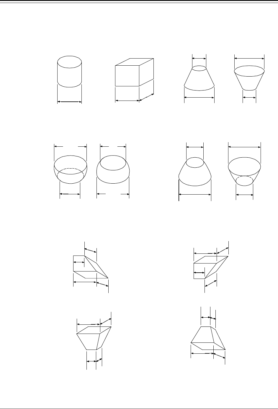
Chapter 3 Set up Level, Level Alarms, and Volume Accu-Wave
3-22 TN Technologies
Figure 3.8 Pre-Defined Tank Shapes and Dimensions
VERTICAL CYLINDER
TYPE 1 VERTICAL RECTANGLE
TYPE 2 VERTICAL CONICAL
TYPE 3
DIAMETER
TOP
DIAMETER
BOTTOM
DIAMETER
WIDTH LENGTH
VERTICAL PARABOLIC
TYPE 5
VERTICAL SPHERICAL
TYPE 4
TOP
DIAMETER
BOTTOM
DIAMETER
TOP
DIAMETER
BOTTOM
DIAMETER
BOTTOM
DIAMETER
TOP
DIAMETER
RECTANGULAR TOP AND BOTTOM
TYPE 7
LENGTH OF
BOTTOM
WIDTH OF
BOTTOM
LENGTH
OF TOP
WIDTH
OF TOP LENGTH
OF TOP
LENGTH OF
BOTTOM
WIDTH OF
BOTTOM
WIDTH
OF TOP
LENGTH OF
BOTTOM
WIDTH OF
BOTTOM
LENGTH
OF TOP
WIDTH
OF TOP
LENGTH OF
BOTTOM
WIDTH OF
BOTTOM
LENGTH
OF TOP
WIDTH
OF TOP
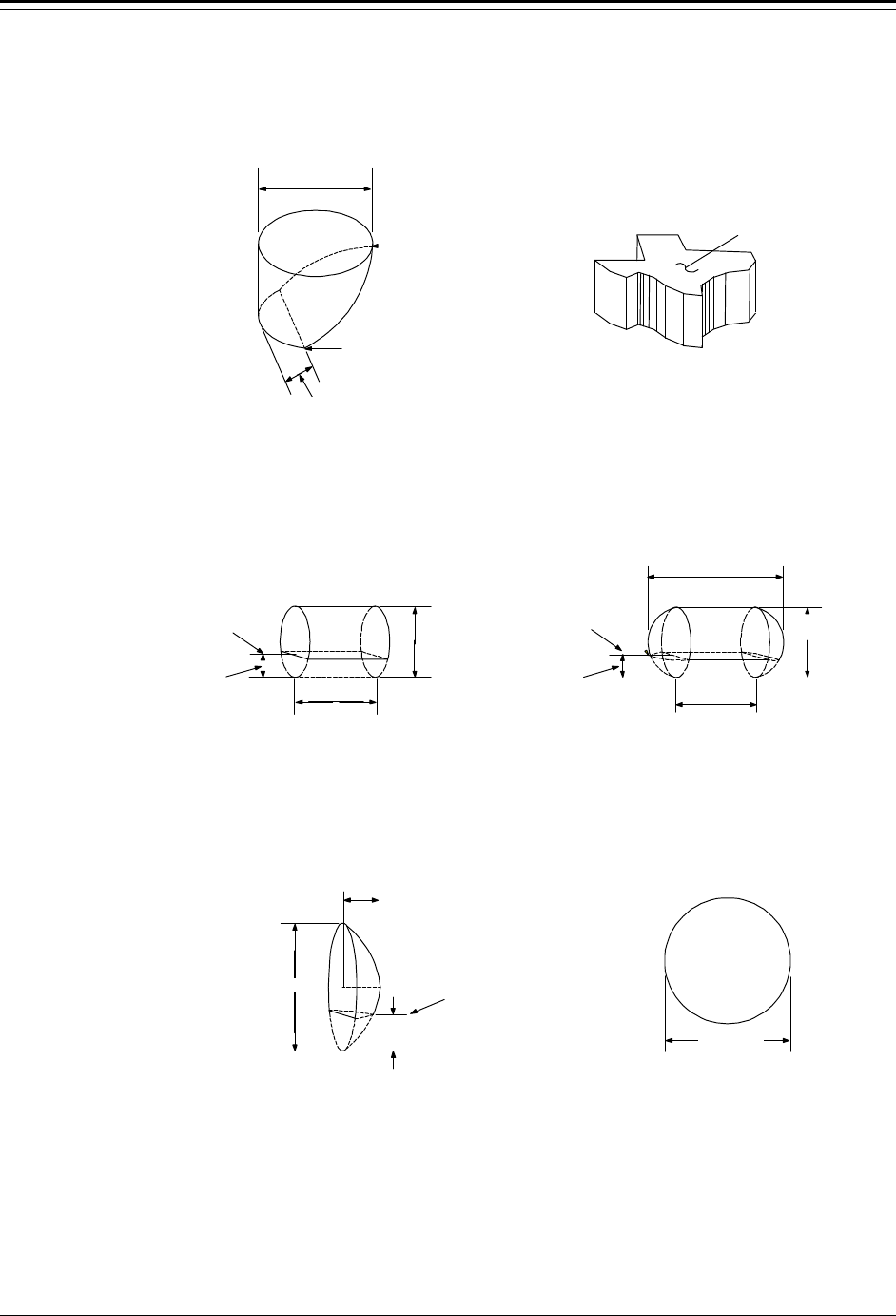
Accu-Wave Chapter 3 Set up Level, Level Alarms, and Volume
TN Technologies 3-23
Figure 3.8 Pre-Defined Tank Shapes and Dimensions (cont.)
DOMED END
TYPE 14
SPHERE
TYPE 18
DIAMETER
WIDTH
(DEPTH)
BOTTOM
OFFSET
BOTTOM OF
SEGMENT
DIAMETER
HORIZONTAL CYLINDER
WITH DOMED ENDS
TYPE 12
HORIZONTAL CYLINDER
WITH FLAT ENDS
TYPE 11
DIAMETER
LENGTH
BOTTOM OF
SEGMENT
BOTTOM
OFFSET
LENGTH NOT
INCLUDING DOMED
ENDS
TOTAL LENGTH
BOTTOM
OFFSET
BOTTOM OF
SEGMENT
DIAMETER
SLOPED BOTTOM
VERTICAL CYLINDER
TYPE 9
ANY SHAPE WITH VERTICAL
SIDES (EXAMPLE)
TYPE 10
AREA
TOP OF
SEGMENT
DIAMETER
BOTTOM OF
SEGMENT
DIM C

Accu-Wave Chapter 4 Set up Additional Measurements
TN Technologies 4-1
Chapter 4 Set up Additional Measurements
As described in Chapter 3, the primary measurement (measurement #1) is set up as either
level or distance using the “Set up level,...” menu. Up to seven additional measurements
can be set up using the “Set up additional measurements” menu. You can use these
measurements to drive a variety of alarms and current outputs to meet the needs of your
processing procedures.
To reach the “Set up additional measurements” menu from the measurement display, press
→ twice. Then press ↓ to enter the menu.
The first time you access the “Set up Additional Measurements” menu, the “Assign & set
up measurement 2” menu will appear. Measurement 1 is assigned to the primary
measurement (distance or level) by default. After measurement 2 is set up, the next time
you scroll through this menu item, it will read “Modify setup of measurement 2.” You will
then be able to “Assign & setup measurement 3,” and so on, up to a maximum of eight
measurements.
The following sections describe the “Set up additional measurements” menu items. The
tables at the end of this Chapter show the individual menu items and the sequence in which
they are displayed.
Selecting Measurement Type
The “Reading presented by measurement # is” menu item allows you to specify the desired
measurement type. Available measurements include:
• distance (outage)
• level
• volume
• ullage (empty volume)
• percent full
• percent empty
• percent distance
• per cent level
• signal strength (sig str)
• mass
• rate
• special measurements, for service diagnostics
Note: Volume related measurements (volume, ullage, % full, % empty, and mass)
are not available for selection until “Tank volume setup” has been
completed under the “Set up Level, Level Alarms, and Volume” menus.
Special measurements are only available when “Service only items” are
enabled (see “Special Functions” on page 8-19).

Chapter 4 Set up Additional Measurements Accu-Wave
4-2 TN Technologies
It is good practice to make a list of all the measurements you set up and
keep the list for future reference.
Select Measurement Menus
“Set up Additional Measurements” Menu
(Specify Measurement Type)
Display Comments
Set up additional
measurements
(readouts).↓↓
Other functions→→
You can assign up to 7 measurements in addition to
the primary measurement. (Primary measurement
setup is described in Chapter 3.) Press ↓ to set up
additional measurements.
NOTE: Meas. #1 is the
primary measurement
See “level setup”
to modify. NEXT↓↓
Measurement #1 is assigned to the primary
measurement by default. (Use the “Set up level,…”
menu to change the primary measurement setup as
described in Chapter 3.)
Assign & set up
measurement 2→→
NEXT↓↓
Press → to assign a readout to measurement 2. After a
readout is assigned to measurement 2, this menu item
will read “Modify setup of measurement 2” and show
the readout assigned, e.g., “cu ft” indicating volume
is assigned to measurement 2.
←←Exit measurement 2
Set up for level,
dist, %lev, %dist,
etc. NEXT↓↓
Info message only. Press ↓ to set up measurement, or
← to exit measurement 2 setup. After measurement 2
is set up, this menu item will read “Change or disable
measurement setup.”
Reading represented by
measurement 2 is
(inactive)
NEXT↓↓ CHANGE→→
Press → to select the readout for measurement 2.
Select from Distance, Level, volume, ullage, % full,
% empty, % distance, % level, sig str, mass, and rate.
You must select a measurement before other setup
menu items will be displayed. Select inactive to skip
or to deactivate a measurement.
Measurement Specific Parameters and Units
Depending on the measurement type selected you will be prompted to enter units and
certain parameters to complete the measurement setup.
Mass Measurement
If mass is selected as the measurement type, you are prompted to select the units from
among the following:
• gram grams
• kgram kilograms

Accu-Wave Chapter 4 Set up Additional Measurements
TN Technologies 4-3
• pound pounds
• metric ton 1000 kg
• short ton 2000 lbs
• long ton 2240 lbs
• oz avoirdupois ounces
After specifying the mass units, you next enter the density of your material. (Mass is
computed as the specified density times the volume measurement.) The value entered for
the density must be in the same units (mass/volume) as specified for the mass and volume
measurements. For example, if you select “pounds” for the mass units and “cu ft” for the
volume units, the density must be entered in units of pounds/cu ft.
Rate Measurement
The rate measurement computes the time rate of change for the selected measurement. The
rate can be computed for any measurement assigned to a measurement number. The rate
can always be computed for the primary measurement (measurement 1). Other
measurements must be set up using the “Assign and set up measurement” menu before the
measurement rate can be computed.
Note: The rate measurement should be set up after setting up the measurement
for which you wish to compute the rate. That is, the number of the rate
measurement should be larger than the number of the base measurement.
The “smallest change for rate” menu item sets a threshold for the change required in the
measurement before the gauge computes a rate value. No rate is computed until the
magnitude of the change in the measurement value exceeds the threshold. Once a rate value
has been computed (i.e., the change in the measurement exceeds the threshold), a new rate
is computed when the threshold is again exceeded, or at the time when the change in the
measurement should have exceeded the threshold based on the last computed rate estimate.
This allows the estimated rate to settle back towards zero if the change in the process
measurement stops.
The “rate smooth factor” menu item determines the degree of smoothing applied to reduce
fluctuations in the rate measurement via exponential averaging. A factor of 1.0
corresponds to no smoothing (estimated rate equals the last computed rate). Use a smaller
rate smooth factor if the measurement tends to fluctuate rapidly, resulting in noisy rate
readouts. The minimum factor is 0.01 and corresponds to the greatest amount of
smoothing.
The “rate time code” lets you select the time interval associated with the rate measurement.
For example, you can measure the change in level per second, per minute, etc. Select from
the following set of time intervals:
• s seconds
• m minutes
• h hours
• d days
• w weeks

Chapter 4 Set up Additional Measurements Accu-Wave
4-4 TN Technologies
• M months
• y years
Measurement Parameter and Units Menus
“Set up Additional Measurements” Menu
(Measurement Specific Parameters and Units)
Display Comments
Note: After selecting a measurement type, menu item(s) prompt for the required
parameters to finish setting up the measurement, as shown below.
If “Distance” or “% distance” are selected, the following menu items are displayed.
Distance units = ft
To change to yd, M,
cm, mm, or in press→→
NEXT↓↓
Available units depend on selection of “All,”
“English,” or “Metric” units under “Set up Level,…”
menus. It is possible (perhaps not often useful) to set
up distance as the primary measurement and as
another measurement number using different units.
No units are required for “% distance.”
Distance REF LINE to
zero distance point
0.000 ft
NEXT↓↓ HELP→→
Appears if distance is not the primary measurement.
Enter the distance from the reference line marked on
the sensor to the desired zero distance point on the
tank.
REF LINE to maximum
distance to be
measured 0.000 ft
NEXT→→ HELP→→
Appears if distance is not the primary measurement.
Enter the distance from the reference line marked on
the sensor to the desired maximum distance point on
the tank.
If “Level” or “% lev” are selected, the following menu items are displayed.
Level units = ft
To change to yd, M,
cm, mm, or in press→→
NEXT↓↓
Available units depends on selection of “All,”
“English,” or “Metric” units under “Set up Level,…”
menus. It is possible (although perhaps not often
useful) to set up level as the primary measurement
and as another measurement number using different
units. No units are required for “% lev.”
Distance REF LINE to
zero level point
0.000 ft
NEXT↓↓
Appears if level is not the primary measurement.
Enter the distance from the reference line marked on
the sensor to the desired zero level point on the tank.
Maximum level
to be measured.
0.000 ft
NEXT↓↓
Appears if level is not the primary measurement.
Enter the maximum level to be measured relative to
the zero level point.
If “Volume” or “sig str” are selected, no additional setup items are displayed. Use
the “tank volume setup” menus under “Set up level,…” to change the volume
parameters.
If “Ullage,” “% full,” or “% empty” are selected, the following additional menu item
is displayed. The units for ullage will be the same as specified for the volume.
100% Volume =
Enter the tank volume when full. The volume of the
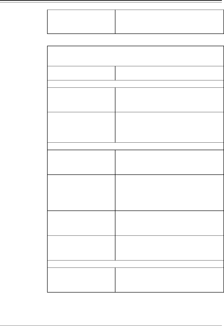
Accu-Wave Chapter 4 Set up Additional Measurements
TN Technologies 4-5
0.000 cu ft
NEXT↓↓
material is computed based on the tank volume setup
and the level measurement. The volume of the tank
when full is required to compute the ullage (empty
volume), the % full and the % empty values.
“Set up Additional Measurements” Menu
(Measurement Specific Parameters and Units) (cont.)
Display Comments
If “mass” is selected, the following menu items are displayed.
Mass
units: Kgram
NEXT↓↓ CHANGE→→
Select the units for the mass measurement. Available
units are: gram, kgram, pound, metric ton, short ton,
long ton, and oz.
material density
0.000 Kgram/cu ft
NEXT↓↓
Enter the material density value. The density value
(mass / volume) must be specified in the same units
selected for mass and volume. Density values < 0.1
are displayed in scientific notation and the units are
not displayed due to display space constraints.
If “rate” is selected the following menu items are displayed.
rate readout will be
rate of:
Distance/time
NEXT↓↓ CHANGE→→
Select a (previously setup) measurement (distance in
this example) for which to compute the rate of
change. Measurement number for rate should be
greater than the number of the base measurement.
Smallest change for
rate compute
0.000 ft dist
2.022E-2 assum NEXT↓↓
Rate will not be computed until the change in the
measurement exceeds the value entered here. Once
rate has been computed, it is recomputed when the
change threshold is exceeded or when the expected
time for the change threshold to be exceeded has
elapsed.
rate smoothing
factor 1.000
{0.01=smoothest}
{0.01 to 1.0} NEXT↓↓
Smoothing factor for rate measurement. A value of
1.0 corresponds to no smoothing (current estimate is
displayed), a value of 0.01 corresponds to the most
smoothing (longest effective averaging time).
rate time code
ft dist/d
Continue↓↓ Change→→
Select the reference time interval for the rate
measurement. Choices are: s (seconds), m (minutes),
h (hours), d (days), w (weeks), M(months), and
y (years).
The next menu item is displayed only if “Service Only Items” are enabled.
special code for
measurement 2 0
see manual
NEXT↓↓
Enter special measurement code. Typically used only
for diagnostic purposes.
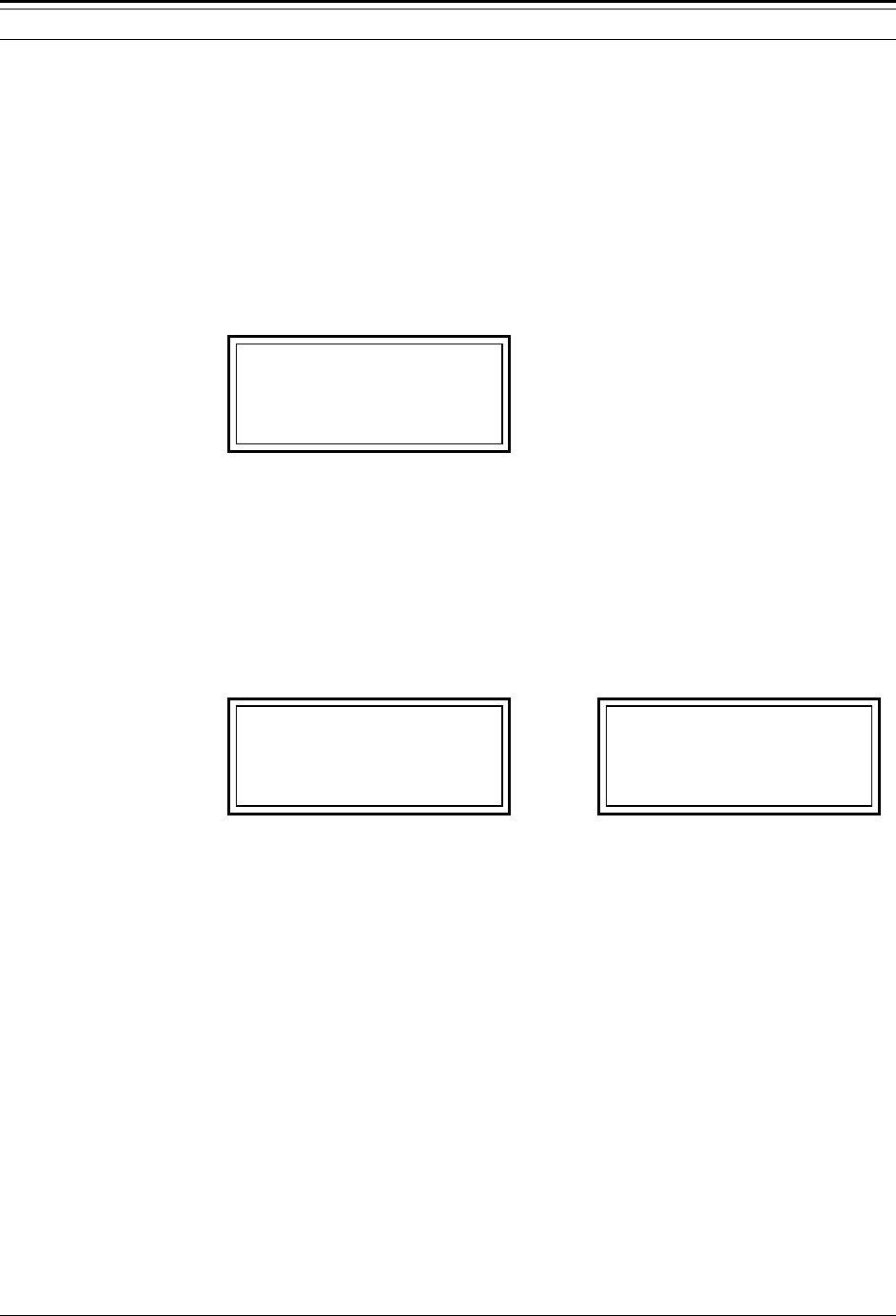
Chapter 4 Set up Additional Measurements Accu-Wave
4-6 TN Technologies
Measurement Display Setup
In the default configuration, the 4-line display can show 3 measurements readouts (or up to
6 measurements by alternately displaying 3 readouts at a time). The fourth line displays
the instruction “For setup, press →.”
Like the primary measurement, the signal strength (sig str) measurement is displayed by
default. If the tank volume setup has been completed, the tank volume is also displayed by
default. For example if you have set up volume, the measurement display would be similar
to the display shown in Figure 4.1 below.
10.5 ft level
78.5 cu ft
114 sig str
For setup press→→
Figure 4.1 Measurement Display (level, volume, signal strength)
The primary measurement is shown on the first line, the volume is shown on the second
line, and the signal strength is shown on the third line. Any additional measurements, up to
six total, would be displayed in alternation with the current measurement readouts. For
example, if measurement 2 is now set up as “%full,” the measurement display would
alternate approximately every 3 seconds between the displays shown in Figure 4.2a and in
Figure 4.2b.
10.5 ft level
64.5 % full
78.5 cu ft
For setup press→→
10.5 ft level
64.5 % full
114 sig str
For setup press→→
a. Display 1 (level, % full, volume) b. Display 2 (level, % full, sig str)
Figure 4.2 Measurement Display (level, volume, signal strength, % full)
To make room for displaying other measurements or to eliminate the need for the display
to alternate between measurement screens, you can disable the display of the “For setup,
press →” instruction on the fourth line of the measurement display. The display of this line
is disabled using a menu item under the “Special functions” menu, see page 8-19.
Note: Pressing the →→ key from the measurement display will access the setup
menus even if the display of the “For setup” instruction is disabled.
If you do not want signal strength to appear on the measurement display, it can also be
disabled using a menu item under the “Special functions” menu, see page 8-19.
You can also disable the display of the primary measurement (measurement 1) as follows.
Use the “Special functions” menu (see page 8-19) to enable the service only items. This
adds a “Modify measurement 1” menu under the “Additional measurements” menu which
includes the “Do / Do not display” option for primary measurement readout.

Accu-Wave Chapter 4 Set up Additional Measurements
TN Technologies 4-7
Do or Do Not Display
Use this menu item to select whether to display the measurement. Normally, any
measurement you set up is automatically displayed. If you select “Do not display,” the
measurement is not displayed, but you can still use the measurement to drive alarms or
current output.
For example, if the volume measurement has been set up, the volume readout will be
displayed by default. It is possible to disable the display of the volume readout, but to still
have the volume measurement enabled to drive an alarm. Use the “Assign & set up /
Modify measurement #” menus to assign volume to a measurement number, and set up the
alarm as described above. Then set the “Do / Do not display measurement #” menu item to
“Do not” to disable the display of the volume measurement. (The signal strength
measurement display can be disabled in a similar manner.)
Display Scaling
A maximum of 4 numeric digits and a decimal point (5 characters total) are available on
the 4-line, 20 character/line measurement readout display. The menu items described in
this section allow you to scale the displayed readout values, so that values greater than
9999 or less than –9999 can be accurately displayed.
As an example, if you set up a volume measurement and expect readings between 30,000
and 40,000 liters, you can use the display scaling menu items to scale the displayed
volume to read in the range 30.00 to 40.00. In this example, the displayed value equals the
measured value (liters) divided by 1000. Thus, the units of the displayed value would be
kiloliters. Display scaling does not affect the units displayed for the readout; however, you
can set up a custom units message.
Note: The following menu items are displayed unless the measurement has been
assigned to a current output (see Current Outputs on page 6-1). If a
current output has been assigned, the “Meas # reading for 20.00 mA
ouptut” and “Meas # reading for 4.000 mA output” menu items for setting
up the current output are displayed. (The “Meas # reading” menu items are
displayed by default for the primary mesaurement, see page 3-2).
Expected reading values and display scaling only affect the readout. They
do not affect the measurement itself. The actual unscaled measurement
values are used for any alarms you assign to this measurement.
Highest Expected Reading
If you expect the maximum measurement readout to exceed four digits (value greater than
9999), enter an estimate of the maximum measurement value in the “Highest expected
reading” menu item. If you set a highest expected reading value of 10,000 or greater (more
than four digits), three additional menu items will be displayed allowing you to set up
display scaling so the gauge’s display will be meaningful throughout the expected range.
The value for the highest expected reading is not critical, just pick a convenient number
with the correct order of magnitude. If the actual measurement happens to exceed the range

Chapter 4 Set up Additional Measurements Accu-Wave
4-8 TN Technologies
you expect, the readout will still display the correct, scaled measurement value, as long as
the scaled value can be displayed in four digits. In our example where 40,000 liters is
scaled to read 40.00 on the display, if the gauge measures 43,875 liters, the displayed
value would be 43.88. Any value up to 99,999 would be displayed correctly, rounded to
four significant digits.
Lowest Expected Reading
This menu item is displayed if you set a highest expected reading value greater than 9999
for a measurement. Use this item to enter the lowest expected measurement value (before
display scaling).
Scale Actual (highest expected reading) to High End Readout
This menu item is displayed if you set a highest expected reading value greater than 9999
for a measurement. Enter the desired readout value to be displayed for the highest expected
reading.
For example, to scale a highest expected reading value of 40,000 to a display value of
40.00, enter 40.00 for the high-end readout value.
Scale Actual (lowest expected reading) to Low End Readout
This menu item is displayed if you set a highest expected reading value greater than 9999
for a measurement. Enter the desired readout value to be displayed for the lowest expected
reading.
For example, to scale a lowest expected reading value of 30,000 to a display value of
30.00, enter 30.00 for the low-end readout value.
Set up custom units messages
This menu item is displayed if you set a highest expected reading value greater than 9999
for a measurement. By default, the original volume units will be displayed for the scaled
value on the measurement display. The “Set up custom units messages” menu items allow
you to set up a user-defined units message up to 10 characters long.
In the above example, the volume measurement with units of liters was scaled by a factor
of 1/1000 (40,000 is displayed as 40.00), so the displayed value has units of kiloliters.
Thus, you might want to set up a custom units message to read “kiloliter.” Up to 8 custom
messages can be defined using any combination of ASCII characters up to 10 characters in
length. Refer to “Setting up Custom Units Messages” on page 8-20 for details.
Position of Decimal
Press the ← and → keys to select the position of the decimal point in the display readout.
This is the last setting that is required for setting up the measurement. You can press ↓
followed by ← to return to the “additional measurements” menu, or press EXIT SETUP to
save changes and return to the normal measurement display.

Accu-Wave Chapter 4 Set up Additional Measurements
TN Technologies 4-9
Set Up Alarm…
The primary measurement is automatically assigned to measurement 1; however, signal
strength, volume, and other measurements are not assigned a measurement number by
default. Therefore, volume, signal strength, and other measurements are not available to
drive the current output, alarms, or relays until you assign them to a measurement number
using the “Set up additional measurements” menu.
Setting up an alarm for a measurement other than the primary measurement is a three step
process. First, set up the measurement using the “Assign and set up measurement #”
menus. Second, assign an alarm to the measurement using the “Assign alarms to
measurements” menu items as described in “Set Up Fault Alarms or Change Process
Alarm” on page 6-3. By default, all alarms are assigned to measurement 1, the primary
measurement. Third, return to the measurement setup menus which will now read “Modify
set up of measurement #,” to set up the alarm.
After assigning one or more alarms to a measurement, the “Set up Alarm” menu items will
be displayed under the appropriate “Modify setup of measurement #” menu under the “Set
up additional measurements” menu, allowing you to set up or modify the alarms. For
example, if you assign alarms 5 and 6 to measurement 3, setup menu items for those
alarms will be displayed when you set up or modify measurement 3.
For details on setting up alarms and a description of the alarm parameters (set point, clear
point, dead band, etc.), refer to “How to Set up Alarms” on page 3-6 which describes
alarm setup for the primary measurement. The alarm setup procedure for other
measurements is the same as for the primary measurement.

Chapter 4 Set up Additional Measurements Accu-Wave
4-10 TN Technologies
Set up Alarm Menu
Note: If relays are installed, the default indicator for alarm N is “controlling relay
N,” even if N exceeds the number of relays. Press →→ to change the alarm
indicator, and the “controlling relay #” options will then correctly reflect
the number of installed relays.
“Set up Alarm” Menu
Display Comments
Set up alarm 3
(Alarm point, etc.)→→
NEXT↓↓
This item only shows up if an alarm (e.g., alarm 3)
has been assigned to the measurement in the “Assign
alarms to measurement” item of the “Set up fault
alarms…” menu (see “Set Up Fault Alarms or
Change Process Alarm” on page 6-3). The alarm
number and the measurement number can be
different.
Note: The appearance of the following menu items depends on the selected
measurement type. You must enter a set point to activate the rest of the Set
up Alarm menu. Example displays show volume (cu ft) measurement.
←←Exit alarm 3 setup
Alarm 3 set point
40.00 cu ft
NEXT↓↓ HELP→→
Enter the measurement value for the alarm set point;
the value at which the alarm is activated.
Alarm 3 clear based
on clr point
Chng to “dead band”→→
Continue as is.↓↓
Select a clear point or dead band configuration. A
clear point is the exact measurement value at which
the alarm is cleared. A dead band specifies the span
between the set point and the implicit clear point.
Alarm 3 clear point
30.00 cu ft
{Makes alarm “Hi”
limit} NEXT↓↓ HELP→→
Enter desired clear point (or dead band) value, the
measurement value at which the alarm is cleared
(turned off). If dead band selected, enter the width of
the dead band relative to the set point.
Alm 3: cu ft
is indicated by
controlling relay 2
NEXT↓↓ CHANGE→→
Select action used to indicate that alarm 3 has been
triggered. The default for alarm N is “controlling
relay N,” if relays are installed. Other selections are:
controlling relay 2 ( 3, 4 if installed)
Meas #1 dispy flash (#2, #3, etc., if measurements
have been setup)
Zero current output 1 (or 2 if installed)
Note: Additional menu items related to controlling relays are shown in the next
table. Other menu items may appear depending on entries you made
elsewhere in the menus.
Set up alarm 4
(Alarm point, etc.)→→
NEXT↓↓
If you assigned more than one alarm (e.g., alarm 4) to
the measurement, menu items will be displayed
allowing the option to set up these other alarms. If
you don’t want to set up another alarm, scroll past
this screen.

Accu-Wave Chapter 4 Set up Additional Measurements
TN Technologies 4-11
The next table presents those menu items specifically related to controlling a relay as an
alarm indicator. As noted in the Comments column, several of the menu items are only
displayed if options have been enabled in the “Special functions” menu. The Special
Functions Menu is described on page 8-19.
“Set up Alarm” Menu (continued)
Relay Indicator Related Items
Display Comments
alarm relay 2 set
delay 0 seconds
(0-255 s after
alarm) NEXT↓↓
Only displayed if “alarm relay delay times” have been
enabled in “Special functions” menu (see page 8-19).
Alarm condition must persist for the time entered for
alarm to be activated.
alarm relay 2 clear
delay 0 seconds
(0-255 s after alarm
has cleared) NEXT↓↓
Only displayed if “alarm relay delay times” have been
enabled in “Special functions” menu (see page 8-19).
Alarm clear condition must persist for the time
entered for alarm to be cleared.
Do not use latching
mode with relay 2.
Change to “Do”→→
Continue as is.↓↓
Only displayed if relay latching has been enabled in
“Special functions” menu (see page 8-19). When
latch mode is enabled for a relay, the relay remains in
alarm state even after the actual alarm is clear. The
relay is cleared by a “Clear alarms” command (see
page 7-3) or when system has been powered off.
Relay 2 turns on
when alarm occurs.
Change to “off”→→
←←Exit alarm 1 setup.
Only displayed if a relay alarm indicator is selected as
the alarm indicator. Non-relay indicators include
zeroing current output, flashing display, or activating
commands.

Accu-Wave Chapter 5 Radar Fine Tuning
TN Technologies 5-1
Chapter 5 Radar Fine Tuning
The basic setup parameters entered via the “Set up Level,…” menu items (see Chapter 3)
establish the measurement range, or the region of interest, along with echo qualification
criteria. The measurement range defines the region over which the Accu-Wave gauge looks
for echoes. The qualification criteria are applied to the received echoes that fall within the
range of interest to identify the “most likely” echo from the surface of the process material.
In many applications, the measurement range and qualification criteria derived from the
basic setup parameters work fine and no further adjustments are required.
In more challenging apllications, additional fine tuning may be required for the Accu-Wave
gauge to lock onto the correct echo from the surface of the material. This chapter describes
the tools available in the Accu-Wave gauge designed to help deal with these more difficult
situations. In addition, this chapter describes how to override the default measurement
range (based on the basic setup parameters) and how to change the measurement
calibration.
Note: The Radar Fine Tuning menu structure has two layers of menu items, the
user layer and the service layer. The default user layer is adequate for
many applications.
The service layer provides several additional tools/menu items (tank
mapping, region weighting, and dynamic tracking) for handling
particularly difficult conditions. These additional tools are not supported
in software versions prior to Version 4.31. The service layer of tools is
intended to be used by an advanced user or by TN’s service personnel.
If you have difficulty configuring your gauge, contact the TN Technical
Support office for assistance.
The Radar Fine Tuning section has four major menus groups.
1. Material Type and Measurement Head Setup
This menu allows you to enter information on the type of material the radar is
reflecting and on the measurement head mounting details. The assumed values for
these parameters will serve in most applications. However, if your unit is not
performing properly, you should enter the actual values for the parameters in this
menu.
2. Modify Range of Measurement
This menu allows you to override the measurement range. These entries will not
change the zero level, maximum level, or zero distance values you may have
already entered. You will be able to extend or constrain the measurement range to
something other than that implied by the basic entries.
3. Response Time, Lost Echo & Agitator Reject Setup
This menu deals with dynamic or time related issues. It provides entries to control
the response time (damping), the action taken when the signal (echo) is lost, and
the response to a temporary loss or change in the echo.

Chapter 5 Radar Fine Tuning Accu-Wave
5-2 TN Technologies
4. False Echo Management
There can be several sources of radar echoes other than the material surface. If the
automatic echo selection criteria are adequate for identifying the echo from the
surface in your application, this menu provides tools to help the system select the
proper echo.
From the measurement display, use the → key to scroll to the “Radar fine tuning” menus.
Press ↓ to enter this menu group and to scroll to the four menu groups listed above. Each
of these four menu groups is discussed in more detail in the following sections.
Material Type and Measurement Head Setup
The “Material type and measurement head setup” menus allow you to enter information
regarding the characteristics of your process material, the process seal, the system to
determine the expected signal strength and any distance offset which might be caused by
your specific process seal. Unless material information is entered, the system uses low
initial amplification to prevent saturation. This configuration will serve in most
applications due to the system’s very broad dynamic range.
If the return signal is weak due to a combination of factors such as a low dielectric process
material plus agitation, the situation may be improved by entering information about the
material. If you select “is not” water based material, the system will increase the initial
amplification to a moderate level. Entering the dielectric constant for your particular
material will allow the system to optimize the initial amplification.
If there are features in your tank that produce a stronger echo than the surface of the
process material, you may see saturation warnings during operation. In this case, you will
need to change the dielectric entry to a higher value. (The gain or amplification setting for
the microwave signal is determined based on the value of the dielectric constant, as the
value of the dielectric constant is increased, the amplification level is decreased.) Even
though such offending signals may be stronger than the proper signal, the system can still
be tuned to select the proper echo. It is important, however, that the initial amplification be
set so that the strongest echo does not cause saturation.
The “spectrum count to average” entry allows the system to enhance weak echoes by
averaging several samples. An entry greater than 8 can slow the response to level changes.
The spectrum averaging is performed prior to performing the echo limiting and echo
rejection tests. Typically, this entry should be left at 1.0 (the default value).
The “Material Type and Measurement Head Setup” menu items are summarized in the
following table.

Accu-Wave Chapter 5 Radar Fine Tuning
TN Technologies 5-3
“Material Type and Measurement Head Setup” Menu
Display Comments
material type and
measurement head
setup→→
NEXT↓↓
Menu entry point for the “Material Type and
Measurement Head Setup” menu group. Press → to
access these menu items, press ↓ to continue to the
next “Radar fine tuning” menu group.
←←Exit from:
material type and
measurement head
setup→→ NEXT↓↓
Press ← to exit this menu group or press ↓ to proceed.
Set gain = 0.000
(1.0 - 40, overrides
automatic value)
{2.711 in use} NEXT↓↓
[Service only item]
If this variable is set to zero (default), the gauge will
adjust the voltage gain of the I.F. (audio) signal
automatically based on the ROI, and dielectric
constant of the process material. If it is set to a non-
zero value, this value is used to override the
calculated gain setting.
Direct Entry Code: ‘029003’
Material in tank
is water based
Change to “is not”→→
NEXT↓↓
This entry selects one of two default (assumed) values
for the dielectric constant of the process material,
which in turn sets the initial gain for the microwave
signal. In most applications, selecting “water based”
or “not water based” is adequate to set the gain. If you
know the dielectric constant for your process
material, you can enter it in the next menu item.
Note: If your application involves more than one
process material with different dielectric
constants, enter the highest dielectric
constant.
Direct Entry Code: ‘025010’
Dielectric constant
of process 0.000
(presently 80.00)
NEXT↓↓
The “presently” assumed value is used for the
dielectric constant of the process material unless you
enter a non-zero value here. The assumed value is
80.00 if you selected “is water based” in the previous
menu item, or 4.704 if you selected “is not water
based.”
Direct Entry Code: ‘028003’
measurement geometry
4 in antenna without
flange mounted seal
NEXT↓↓ CHANGE→→
Select “antenna without flange mounted seal” for an
intrusive sensor mounting configuration or change to
“antenna with flange mounted seal” for the isolation
sensor configuration.
Direct Entry Code: ‘005002’

Chapter 5 Radar Fine Tuning Accu-Wave
5-4 TN Technologies
“Material Type and Measurement Head Setup” Menu (continued)
Display Comments
flange mounted seal
velocity correction
value = 0.000
NEXT↓↓ HELP→→
Displayed if “antenna with flange mounted seal” is
selected above. Enter velocity correction value (in cm)
to correct for the reduced propagation velocity of the
process seal(s). See Error! Reference source not
found.. If this value is left at zero, the process seal
will induce a small offset error.
Direct Entry Code: ‘086003’
spectrum
count to average 1
(1 - 64)
NEXT↓↓ HELP→→
Increase number of averages to improve measurement
on non-agitated low dielectric materials such as light
hydrocarbons. Values over 8 can slow the response of
the gauge. Do not use values > 1 on agitated to
turbulent surfaces.
Direct Entry Code: ‘022004’
Optimize system for
best Accuracy
Chg to “Resolution”→→
Continue as is.↓↓
[Service only item]
Use default value for best accuracy. Changing to
“Resolution” can somewhat improve ability to resolve
closely spaced echoes at the cost of a slight decrease
in the accuracy of the distance/level measurement.
Modify Range of Measurement
To maximize resolution and minimize false echoes, the system establishes a Range of
Interest (ROI) over which it looks at candidate echoes. The default ROI is based on values
entered during the primary measurement setup (see page 3-2). If the primary measurement
is level, the ROI extends from the zero level point to the maximum level point. If distance
is the primary measurement, the ROI extends from the zero distance point to the maximum
distance point.
Using the “Modify Range of Measurement” menu items, the ROI can be modified to allow
measurements below the zero level (readout will show a negative level) or above the
“maximum” level. Alternately, the ROI can be set to exclude the zero level point.
The slope correction and distance offset correction entries allow you to fine tune the
gauge’s distance measurement to correct for any variations due to the gauge installation or
to adjust the gauge’s readout to match the distance / level readings from another level
measuring device.

Accu-Wave Chapter 5 Radar Fine Tuning
TN Technologies 5-5
“Modify Range of Measurement” Menu
Display Comments
Distance REF LINE to
highest possible
level 0.000 ft
NEXT↓↓ HELP→→
Defines top of the ROI. If this entry is 0.0, the top of
the ROI is set by the maximum level (or zero distance
point) entry for the primary measurement. A non-zero
entry here overrides the default value for the top of
the ROI, and defines the closest echo processed. The
gauge will not correctly measure above this level.
Minimum value is 2.12 m (0.691 ft).
REF LINE to maximum
distance to be
measured 0.000 ft
NEXT↓↓ HELP→→
Defines bottom of the ROI. If entry is 0.0, the bottom
of the ROI is set by the zero level (or maximum
distance point) entry for the primary measurement. A
non-zero entry here overrides the default value for the
bottom of the ROI, and defines the farthest echo
processed. The gauge will not measure correctly
below this level. Maximum value is 34 m (112 ft).
Slope correction
factor 1.000
NEXT↓↓ HELP→→
Adjust gauge readout using following equations:
Distance = slope factor x (meas. value + offset).
Level = zero level point – distance
Limit slope factor value to range of 0.995 and 1.005.
Consult TN if this value needs to be changed.
Direct Entry Code: ‘049003’
Distance offset
correction
0.000 ft
NEXT↓↓ HELP→→
Offset value for gauge readout adjustment equations
(see entry above). Mounting imperfections can cause
up to 0.10 ft offset error. Limit offset value to range
of 0.0 to 0.16 ft (0.05m). Consult TN if this value
needs to be changed.
Direct Entry Code: ‘031003’

Chapter 5 Radar Fine Tuning Accu-Wave
5-6 TN Technologies
Response Time, Lost Echo, and Agitator Reject Setup
The “Response Time, Lost Echo, and Agitator Reject Setup” menus provide entries to
control the system response time, what action to take when the signal (echo) is lost, and the
response to a temporary loss or change in the echo.
When the Accu-Wave gauge is first turned on, the system begins processing the echoes
received from the microwave transmission to identify the true echo from the material
surface. Each time the gauge transmits a microwave signal, multiple echoes are received
by the sensor. The source of these echoes can include reflections from:
• the surface of the material (the proper or true echo)
• layers within the process material such as foam or oil–water interface
• streams of liquid filling the tank
• the tank bottom as seen through the process material
• agitator blades
• structural features in the tank
• multiple bounces from the various internal surfaces of the tank
• structures relating to the entry of the microwave signal into the tank
Echoes which fall within the range of interest (minimum to maximum distance) defined by
your setup entries for the primary measurement are included in the group of candidate
echoes, which are analyzed to select the “best” candidate for the echo from the surface.
If the location of the best candidate echo remains consistent (falls within a range gate) over
several transmissions, the system locks onto this echo as being the “true” echo from the
material surface. Echoes from subsequent transmissions are then analyzed. If the location
of the best candidate echo falls within a range gate centered on the average location of the
current, true echo (the present distance readout), the echo is considered valid, and the
distance measurement of this echo is used to update the measurement readout. If the echo
does not satisfy the range criteria, the group of echoes from a new transmission is
processed and a new echo report is generated. This process is repeated until the best
candidate echo passes the range gate criterion, or until a new “true” echo is confirmed at a
new location through its persistence.
Range Gate
The range gate defines the acceptance window which moves with the level (or distance)
readout. When the gauge is powered up or when the system switches to the “echo is lost”
mode, the range gate is in the not captured mode. After a certain number of “hits” (best
echo candidates which fall inside the range gate), the range gate switches to the captured
mode, that is, the gauge locks on to an echo as the true echo. When the range gate is in the
not captured mode, all “best candidate” echoes from successive transmissions are used to
update the measurement readout.
Once the range gate is in the captured mode, a “best candidate” echo is only used if:
• The echo distance falls within the range gate

Accu-Wave Chapter 5 Radar Fine Tuning
TN Technologies 5-7
• “Do bypass range gate for near echoes” has been selected and the echo falls short
of the range gate
• “Do bypass range gate for far echoes” has been selected and the echo falls beyond
the range gate
• Past echoes have fallen outside of the range gate for a period equal to the “agitator
reject time” (range gate delay time)
If none of the above conditions are met, the next transmission is processed, a new echo
report is generated, and the entire process is repeated until one of the above conditions is
met. If no echo meets the above conditions for a specified period of time (the range gate
delay time), the echo is considered lost and the gauge will be in the “waiting for echo”
state. A second time parameter (time after echo loss before lost echo mode) defines the
time between the initial loss of the echo and when the gauge enters the lost echo mode, that
is, the range gate reverts to the not captured mode.
The optional selections to by-pass the range gate for near echoes, far echoes, or all echoes
are typically not required. The “by-pass near” selection can be used to provide a fast
response to rising level, while delaying response to echoes which appear to be beyond
(below) the material level. Similarly, the “by-pass far” selection can be used to provide a
fast response to decreasing level, while delaying response to echoes which appear to be
above the material level. This is one of several tools which may be used in combination to
reject multi-bounce echoes or echoes from the bottom of the tank as seen through a low
dielectric material.
Agitator Reject Time
The persistence (time) required to accept a new “true” echo, which falls outside the range
gate of the current true echo, is determined by the “Agitator reject time” (range gate delay)
entry.
As implied by its name, a primary purpose of the “agitator reject time” is to reject false
echoes due to an agitator that may have blades above the material surface or to delay loss
of echo. The reject time should be set to the time required for the blade to pass through the
microwave beam. The beam diameter increases by about one foot for each four foot
increase in distance from the top of the tank. For example, if the agitator blade is 20 feet
from the top of the tank, the beam can be considered to be about 5 feet wide. Based on this
beam width and the agitator speed, you can determine an appropriate entry for the agitator
reject time.
The range gate feature can also provide cleaner operation with agitated surfaces. In such
applications, momentary loss of the proper echo can cause the system to use a false echo
from some structure in the tank. Setting an agitator reject time of a few seconds will cause
the system to make many tries to get an echo close to the previous surface position before
accepting other echoes.
If a long agitator reject time is entered, the response of the system to fast changes in level
may be delayed. In some cases, this delay can be dealt with by selecting “Do” by-pass
range gate for far echoes. In this configuration, the system will perform range gate
processing on echoes which are closer to the measurement head than the measured level,

Chapter 5 Radar Fine Tuning Accu-Wave
5-8 TN Technologies
but will allow any echoes beyond the level (lower) to be accepted without considering the
range gate.
Note: If you want to use an agitator reject time entry of “forever,” enter 65535
seconds.
Range Gate Weighting Factor (GWF)
A range gate weighting factor (GWF) can be applied to echoes that fall within the range
gate. A GWF value greater than 1 gives additional preference to echoes within the range
gate during the processing to select the best candidate. A GWF value less than 1 reduces
the preference given to echoes within the range gate.
You may also affect the system response by changing the height (span) of the range gate.
The default value for the range gate height is 25 cm (~10 in). Entering a larger value for
the range gate height would increase the number of echoes considered valid and which
could be used to update the current measurement values.
Using a larger range gate height and a short time constant value would allow the range
gate to move quickly as the actual material level moves and would give the system a good
chance of getting usable echoes from the material before it moves out of the range gate.
Using a smaller range gate height can improve accuracy in turbulent applications but can
also slow response depending on the range gate delay used.
The “long” range gate delay configuration would be used to deal with extended process
changes such as a filling stream or the actual level going outside the range of interest. In
such cases, the range gate delay should be set to the longest expected duration of the
“unusual” process condition. A greater time-out should only result from a lost level
condition.
Response Time, Lost Echo and Agitator Reject Setup Menus
The following table describes the individual menu items available under the Response
Time, Lost Echo and Agitator Reject Setup menu group. Menu items that require the
“Service only items” to be enabled include the notation [Service only item].

Accu-Wave Chapter 5 Radar Fine Tuning
TN Technologies 5-9
“Response Time, Lost Echo and Agitator Reject Setup” Menu
Display Comments
Level Signal
time constant
4 seconds
NEXT↓↓ HELP→→
Time constant for smoothing filter applied to the
primary measurement (level or distance). Range of
time constant value is from 1 to 1000 seconds. The
longer the time constant, the greater the smoothing,
and the slower the response of the system. Default
value is 4 seconds.
Direct Entry Code: ‘007004’
echo loss mode is
hold last value
NEXT↓↓ CHANGE→→
When in “lost echo” mode (when gauge loses the
return signal), display reports: “Echo lost.” Select one
of the following actions:
hold last value
go to hold value (enter value in next menu item)
go to maximum possible distance
go to zero distance point
Direct Entry Code: ‘142002’
Level hold mode
& lost echo value
0.000 ft level
NEXT↓↓
Only displayed when “go to hold value” is selected
for the echo loss mode in the previous menu item
Direct Entry Code: ‘037003’
time after echo
lo
ss before going to
lost echo mode
4 seconds NEXT↓↓
Delay time between echo loss and switch to “lost
echo” mode. During this period display will report:
“Waiting for echo.” Enter the length of time the
gauge waits before going to the signal loss mode
selected above. The default is 4 seconds.
Direct Entry Code: ‘029004’
Agitator reject time
1.000 sec
(range gate delay)
NEXT↓↓ HELP→→
Agitator reject time is the delay time before accepting
an echo outside the range gate. The range gate is a
window that moves with the “measured” level.
During this period display reports: “Waiting good
echo.” Used to reject false echoes caused by an
agitator blade passing through the signal.
Direct Entry Code: ‘044003’
height of range gate
(moving window)
0.000 ft
NEXT↓↓ HELP→→
Enter height of range gate which is centered on the
distance measurement readout. A larger window will
admit a larger number of signals as possibly valid. If
this variable is set to 0.0, the gauge will use the
default value of 25cm (± 12.5cm) range window.
Direct Entry Code: ‘019003’

Chapter 5 Radar Fine Tuning Accu-Wave
5-10 TN Technologies
“Response Time, Lost Echo and Agitator Reject Setup” Menu (continued)
Display Comments
Increase range gate
height by 0.000% of
distance to surface
NEXT↓↓
[Service only item]
This variable can be used to increase the range gate
hieght by a percent of the distance to the surface.
Direct Entry Code: ‘043003’
weighting factor
(GWF) for echoes
inside range gate.
0.000 NEXT↓↓
[Service only item]
During the echo selection process, echoes within the
range are weighted by the preference factor. If this
variable is set to 0.000 (default), no additional
preference is given to echoes within the range gate.
Entering a value greater than 1.0 will help the gauge
track the process material.
Direct Entry Code: ‘064003’
Capture range gate
after 0 “hits”
{128 assumed}
NEXT↓↓
[Service only item]
This is the number of hits within the range gate
window before the gauge would enter capture mode.
If this variable is set to 0.000 (default), the gauge will
use a default value of 32 times the value set for the
time constant.
Direct Entry Code: ‘011004’
Do un-
capture
range gate @ timeout
Change to “Do not”
NEXT↓↓
[Service only item]
If gauge does accept an echo within the range gate
within the agitator reject time, the variable instructs
either “Do” or “Do not” remain in capture mode. “Do
not” would mean the range gate window would not be
used until capture mode is re-established.
Direct Entry Code: ‘040050’
disable range gate
until re-capture
←←Exit this menu
NEXT↓↓ EXECUTE CMD→→
[Service only item]
Executing this command will disable the range gate
until capture mode is re-established. This command is
useful if a large Preference Factor or a long Agitator
Reject Time is preventing the gauge from requiring
the correct echo (process material).
Direct Entry Code: ‘37’ (Command)
Do not bypass range
gate for near echoes.
Change to “Do”→→
Continue as is.↓↓
Open the range gate to closer echoes.
Direct Entry Code: ‘029040’
Do not bypass range
gate for far echoes.
Change to “Do”→→
Continue as is.↓↓
Open the range gate to farther echoes.
Direct Entry Code: ‘029050’
Do not bypass range
gate for all echoes.
Change to “Do”→→
Continue as is.↓↓
Open the range gate to all echoes.
Direct Entry Code: ‘029080’

Accu-Wave Chapter 5 Radar Fine Tuning
TN Technologies 5-11
False Echo Management
Use the “False echo management” menu to correct false readings caused by unwanted
echoes.
False echo management has three primary approaches to eliminating false echoes. The first
is to constrain the set of candidate echoes to the smallest group that will reliably include
the desired echo. The second applies test criteria that can reject some of the unwanted
echoes. The third is to apply weighting factors to the remaining candidate echoes to
enhance the echo from the material while suppressing all other echoes.
Note: A good understanding of the echo report is necessary before using the
Radar Fine Tuning tools to deal with a difficult application.
Echo Report (View Echoes Being Processed)
The first item in the “False echo management” menu is the “view echoes being processed”
menu. Each screen in this menu describes one echo in the candidate set.
You should be able to correlate the echoes in the echo report with the physical layout of
your tank. First, identify which echo is from the material surface (based on its distance).
Echoes at distances greater than the echo from the surface of the material are normally the
result of multiple reflections or bounces. If the material is a low dielectric, such as
hydrocarbon, one of the more distant echoes may be from the bottom of the tank.
Echoes that appear at distances closer than the material surface are typically from pipes or
baffles. If you cannot associate echoes near the top of the tank with physical features, they
may be “phantom” echoes from multiple bounces in the entry nozzle or mounting
structure. The tools described in this chapter can be used to reject echoes caused by
mounting structures. The best approach is to minimize the number and signal strength of
these reflections by carefully mounting the Accu-Wave Sensor following the guidelines in
the Accu-Wave Installation and Maintenance Manual provided with your gauge.
A typical display from the echo report is shown below:
echo 2 of 6 (#4)
Q1 = 180: 33.75 ft
Q2 = 45 : 22.11
SigStr
SWF = 0.500 NEXT↓
The first line of the display indicates that this echo report is for echo number 2 out of a
total of 6 candidate echoes. The “(#4)” notation indicates that echo number 4 has been
selected as the “best” echo. Note the echoes are numbered with echo 1 being the farthest
from the sensor, echo 2 being the next farthest, and so on. In this example, echo 6 would
be the closest echo to the sensor (among the set of candidate echoes that fall within the
range of interest).

Chapter 5 Radar Fine Tuning Accu-Wave
5-12 TN Technologies
The second line shows that the Q1 echo quality factor for echo 2 is 180 (larger values
indicate better quality). The distance of echo 2 relative to the reference line on the sensor is
33.75 ft.
The third line shows that the Q2 echo quality factor for echo 2 is 45 (again larger values
indicate better quality). The signal strength of echo 2 is 22.11, before any weighting
factors or other selection modifiers are applied.
Finally, the fourth line of the display shows the value of the Successive Weighting Factor
(SWF).
Limiting the Number of Echoes to Process
The system only analyzes echoes that fall in the range of interest (ROI) and that are
stronger than the minimum signal strength. The ROI is initially defined by the primary
measurement setup entries. To limit the number of echoes processed, you can modify the
range of interest. You can also modify the values for the “maximum number of echoes to
be processed” (default value is 8) and/or the “minimum allowable signal strength” (default
value is 3). Using the default values, the strongest echoes (up to 8) with signal strength > 3
are considered as the candidate echoes. The “Clutter Data Management” menu items can
be used to remove “phantom” echoes which fall within the ROI. To optimize Accu-Wave
performance, you should constrain the set of candidate echoes to the smallest group that
will reliably include the desired echo (echo from process material).
Note: Only a few of the Radar Fine Tuning tools actually alter the echo report -
the minimum allowable signal strength, the maximum echo count to
process, the clutter data management, and modifying the range of interest
(ROI).
None of the other Radar Fine Tuning tools alter the echo report. These
other tools and weighting factors are applied to the signal strength in the
echo report to select the best echo from the set of echo candidates.
Echo Rejection
Several of the menu items under the “False Echo Management” menu are used to reject
unwanted echoes. These items do not alter the echo report, but do modify the echo
selection process. The three tools used to eliminate echoes from being considered as
candidate echoes are:
1. The “maximum desired signal strength” can be used to reject echoes that are
stronger than the desired echo. This capability may be used to reject very strong
false echoes while allowing the weighting factor to be set to deal with other
situations.
2. “Q1 and Q2 quality factor rejection” criteria can be used to reject any echo which
has a low Q1 and/or Q2 quality factor value.
3. “Tank mapping” can be used to specify the location of physical targets within an
empty tank and have the gauge ignore echoes from these targets. (See “Tank Map
Setup” on page 5-21.)

Accu-Wave Chapter 5 Radar Fine Tuning
TN Technologies 5-13
Warning: If the desired echo’s signal strength exceeds the “maximum desired
signal strength,” the desired echo will be rejected, unless it is the only
candidate echo.
If the quality factor of the desired echo does not exceed the quality
factor rejection threshold, the desired echo will be rejected.
Echo Weighting Factors
There are four echo weighting tools available for difficult applications.
1. Successive Weighting Factor (SWF) - Factor applied to the signal strength of an
echo before comparing it to the next closer echo to determine which is the most
likely candidate (default value is 0.5).
2. Range Gate Weighting Factor (GWF) - Increases the weight of the echoes within
the Range Gate. See “Response Time, Lost Echo and Agitator Reject” on page 5-
6.
3. Region Weighting Factors - Tank is divided into regions (2 to 8) and an additional
custom weighting factor is assigned to each of the regions. See “Region Weighting
Setup” on page 5-24.
4. Map Echo Weighting Factor - Applied if tank mapping is set to derate (rather than
ignore) mapped echoes. See “Tank Map Setup” on page 5-21.
The successive weighting is the most commonly used tool for adjusting echo selection and
is the only echo weighting factor used by default. When activated, the other three echo
weighting factors are used to weight the signal strength of the echoes in the echo report
prior to parsing the report using the factor SWF.
The SWF is applied as follows:
1. The echo report is parsed from the farthest echo (echo #1 in the echo report) to the
closest echo (last echo in the echo report) based on weighted signal strength.
2. The SWF is applied to echo #1 (farthest from the gauge). For example, if the
signal strength of echo #1 was 1000, after applying the SWF (default value = 0.5),
the weighted signal strength of this echo would be 500.
3. The weighted signal strength of echo #1 is compared sequentially to the non-
weighted signal strength of echoes 2 through N. Echo #1 would be replaced as the
“best” candidate by the next closer echo with a signal strength greater than the
weighted signal strength of echo #1.
4. This process continues until a final “best candidate echo is chosen, that is, an echo
with a weighted signal strength which exceeds the non-weighted signal strengths of
the remaining, closer, candidate echoes.
A smaller Successive Weighting Factor helps suppress more distant echoes which might be
from multiple reflections. This situation can occur with high dielectric materials such as
water. A larger weighting factor helps suppress closer echoes that might be from structural
features. This situation can occur with low dielectric materials such as hydrocarbons,
where the good echo can be weaker relative to closer, spurious echoes.

Chapter 5 Radar Fine Tuning Accu-Wave
5-14 TN Technologies
Example: Locking on to False Target Closer (higher) than Material Surface
When the process material has a low dielectric constant, the return signal from the material
surface can be weaker than the echoes from false targets. If there is a pipe or other artifact
(false target) in the tank above the surface level of the process material, the gauge may
lock on to the echo from the false target with the strongest signal rather than locking on to
the proper echo from the material surface.
Note: If the dielectric constant of the process material is below two, call TN
Technologies and speak with a Microwave Applications Specialist.
To make the system favor the more distant (proper) target, enter a larger value for the
successive weight factor. Use a weighting factor large enough so that the signal strength of
the proper target multiplied by the weighting factor is at least twice as large as the signal
strength of any of the closer, false echoes.
In some instances, using a large weighting factor (to deal with close echoes) can cause the
system to lock on to bottom of tank. Use the ‘bottom echo signal strength factor” and
“Distance REF LINE to tank bottom” menu items to mask the tank bottom.
Example: Locking on to False Target Farther (lower) than Material Surface
With high dielectric materials, such as water, multiple reflections can occur depending on
the shape of the tank. Use a smaller successive weighting factor to exclude these relatively
strong, more distant echoes. Select a weighting factor small enough so that the signal
strength of any false echo multiplied by the weighting factor is less than half as large as the
signal strength from the closer, proper target.
The use of a very small weighting factor to favor close echoes can cause the system can
lock on to relatively weak, close artifacts instead of the proper target. This complication
can often be handled by limiting the number of echoes processed. Be careful to ensure that
the number of echoes processed is large enough to always include the echo from the actual
material surface.
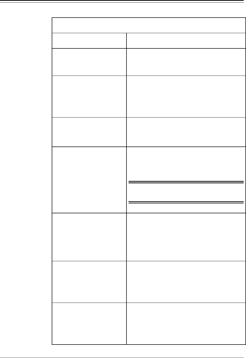
Accu-Wave Chapter 5 Radar Fine Tuning
TN Technologies 5-15
“False Echo Management” Menu
Display Comments
View echoes being
processed→→
NEXT↓↓
Allows you to examine the echo report for each echo
within the range of interest. Press → to access the
echo reports, then press ↓ to scroll through the echo
reports. The echo report is described on page 5-11.
echo amplitude
successive weighting
factor(SWF)=.5000
NEXT↓↓ HELP→→
The successive weighting factor is applied to the
signal strength of each echo before it is compared to
the next closer echo. The same weighting factor is
used for each echo. This is part of the process of
selecting the “best candidate.”
Direct Entry Code: ‘007003’
Minimum allowable
signal strength
3.000
NEXT↓↓ HELP→→
Only echoes with a signal strength equal or greater
than this value will be reported as a possible
candidate.
Direct Entry Code: ‘108003’
maximum desirable
signal strength
0.000
NEXT↓↓ HELP→→
If this variable is set to 0.000 (default), the gauge will
not use this function to reject echoes. If this variable
is set to a non-zero value, the gauge will reject any
echo greater than this value unless there are no other
candidates. Used to reject strong unwanted echoes.
Warning: If the desired echo exceeds this setting,
the desired echo will be rejected unless
it is the only candidate echo.
Direct Entry Code: ‘104003’
maximum echo count
to be processed 8
NEXT↓↓ HELP→→
This item limits the number of echoes which the
gauge will process. Enter a value between 1 and 24.
For the default value of 8, the strongest echoes (up to
8 maximum) which exceed the minimum allowable
signal strength and which fall within the ROI are
reported as candidate echoes.
Direct Entry Code: ‘025004’
Reject echoes with
Q1 below 0
NEXT↓↓
[Service only item]
Enter minimum value for quality factor Q1 (0 - 255).
If a non-zero value is entered, any candidate echo
with a Q1 value less than this minimum value will be
rejected. A 0 entry (default) disables the rejection of
candidate echoes based on the Q1 value.
Direct Entry Code: ‘043004’
Reject echoes with
Q2 below 0
NEXT↓↓
[Service only item]
Enter minimum value for quality factor Q2 (0 - 255).
If a non-zero value is entered, any candidate echo
with a Q2 value less than this minimum value will be
rejected. A 0 entry (default) disables the rejection of
candidate echoes based on the Q2 value.
Direct Entry Code: ‘044004’

Chapter 5 Radar Fine Tuning Accu-Wave
5-16 TN Technologies
“False Echo Management” (continued)
Display Comments
bottom echo
signal strength
factor 0.000
NEXT↓↓
[Service only item]
When set to 0.0 (default), this factor is not used in the
echo selection process. When a non-zero value is
entered, this weighting factor is applied to echoes at
the “distance (from the) REF LINE to tank bottom”
(next menu item) and beyond in the echo selection
process.
Note: Limit setting between 0.05 to 1.0. If this
setting needs to be changed, consult TN.
Direct Entry Code: ‘121003’
Distance REF LINE to
tank bottom
0.000 ft
NEXT↓↓
[Service only item]
This item works in combination with the previous
item.
Direct Entry Code: ‘054003’
spectrum cutoff
point 91.00 %
NEXT↓↓
[Service only item]
Do not modify this value.
Clutter data
management→→
NEXT↓↓
Press → to enter the “Clutter data management”
submenu. See the next section for details.
tank map setup→→
NEXT↓↓
[Service only item]
Press → to enter the “tank map setup” submenu. This
submenu is used to map and reject false echoes in an
empty tank. See page 5-21 for details.
region weighting
setup→→
NEXT↓↓
[Service only item]
Press → to enter the “region weighting setup”
submenu. This submenu lets you divide the tank into
regions (up to 8) and assign a different weighting
factor to each region. See page 5-24 for details.
Minimum allowable
post weighting
signal strength
0.000 NEXT↓↓
[Service only item]
Enter desired threshold value. Default value of 0.0
disables this threshold test. When a non-zero value is
entered, only echoes with a weighted signal strength
greater than or equal to this value are reported as
candidate echoes.
dynamic threshold
setup→→
NEXT↓↓
[Service only item]
Press → to enter the “dynamic threshold setup”
submenu. This submenu defines parameters which
help track a turbulent process while still providing a
quick and reliable update response. See page 5-26 for
details.

Accu-Wave Chapter 5 Radar Fine Tuning
TN Technologies 5-17
Clutter Data Management
Imperfections in the transition from the microwave head to the tank can cause microwave
energy to be reflected. These imperfections can be due to poor alignment of the nozzle pipe
during welding, pipe size mismatch, joints, valves, pipe liner, or material buildup.
Although the physical source of these reflections is normally outside the range of interest
(at or above the top of the tank), multiple bounces can cause these “phantom” echoes to
appear to be in the range of interest. These echoes will persist even when the actual
material level rises above the apparent distance to the phantom targets. These phantom
targets are referred to as clutter.
Erase Clutter
Even if these phantom echoes are not strong enough to confuse the system in the selection
of the proper echo, this clutter can cause errors when the distance to the material surface is
close to the distance associated with a phantom target. The effects of phantom targets can
be reduced by the use of clutter erase.
The gauge “learns” the phantom signals and mathematically removes them from
consideration. During the learn clutter (“Get clutter data”) operation, the system stores all
of the apparent target information over the maximum possible clutter zone, ~ 7.4 ft (2.25
m) or 25% of the maximum measurement distance, whichever is greater.
User Considerations
The gauge always measures the clutter data out to a fixed, maximum clutter distance. You
then specify the distance from the reference line for which the actual clutter removal is
performed. The clutter data will include any real (physical) targets located between the
reference line and the maximum clutter distance. It is essential that the specified clutter
removal distance not include any actual physical targets which might be covered by the
material surface during normal operation. (See the “Tank map setup” or “Regional
weighting setup” section in the chapter for information on how to mitigate the effect of
these reflections.)
The user-entered clutter distance must be at least 30 cm (~12 in) above the level of the
process material when the clutter data is taken. Otherwise, part of the real target’s echo
data will be considered to be clutter.
The measurement range can be essentially anything up to the maximum system capability.
However, the internal range is normally from about 8 m (27 ft) to the maximum system
capability. For user-entered ranges below the internal minimum, the system ignores targets
between the top of the range of interest and the internal minimum. The range of interest is
established by the “zero level point” entry, if the primary measurement is level. The ROI
can be overridden by the “maximum distance to be measured” entry.
If anything in the setup entries causes the internal range or the initial amplification to
change after clutter data has been taken, clutter erase will be disabled and the “bad entry”
message will be displayed. Initial amplification is normally a function of the dielectric
constant and the range of interest-related entries. The bad data message can be suppressed

Chapter 5 Radar Fine Tuning Accu-Wave
5-18 TN Technologies
by taking new clutter data, selecting “Do” disable clutter erase, or entering a clutter
distance of zero (which disables the clutter erase feature).
The need for clutter erase can be established by viewing the echo report. Look for echoes
within a few feet (up to 7 ft or 2 m). If the signal strength associated with these echoes is
more than 5% of the signal strength from the material surface, you should consider doing
clutter erase. If the signal strength associated with these echoes is more than 50% of the
signal strength from the material surface, you should verify the sensor mounting.
The clutter distance may be entered or changed before or after clutter data is taken.
However, the clutter distance must always be at least 30 cm (1 ft) less than the distance to
the material surface when clutter data was taken. In addition, the clutter distance must not
be extended to include any true physical sources of echoes (such as pipes) that might be
covered during normal operations.
Automatic Clutter Update
In most applications which require clutter erase, the clutter data is only taken once.
However, in applications where the clutter echoes are strong and the clutter can change
due to buildup or ambient temperature extremes, automatic timed clutter data may be
employed.
Timed clutter data is activated by entering a clutter update time from a minimum of 1
minute to a maximum value of 45 days (65000 minutes). At the end of each clutter update
interval, the system activates the clutter update process. The system waits to measure the
clutter data until the measured level is at least 30 cm (1 ft) beyond the value entered for the
clutter distance.

Accu-Wave Chapter 5 Radar Fine Tuning
TN Technologies 5-19
“Clutter Data Management” Menu
Display Comments
Clutter distance
{from REF LINE}
0.000 ft
{7.826 MAX} NEXT↓↓
If this entry is 0.0, the Clutter Data Mgmt menu items
will not be displayed. Maximum allowable clutter
distance is 7.147 feet or 25% of the maximum
measurement range, whichever is greater. When a
clutter erase command is executed, clutter data is
collected to the maximum clutter distance. The
“Clutter distance” defines which portion (or all) of
the clutter data will be removed from the spectrum.
Do not disable
Erase clutter
Change to “Do”→→
Continue as is.↓↓
May be used to disable clutter erase for diagnostic
purposes.
Direct Entry Code: ‘041080’
Get clutter data &
save result.
←←Exit this menu.
NEXT↓↓ EXECUTE CMD→→
Press → to execute the “Get clutter data” command.
The distance to the material surface must be greater
than the clutter distance value, or the valid echo will
be removed as clutter. The actual level can reach the
clutter area during operation, but can not rise above
any physical features associated with the clutter.
Note: Clutter Erase is best performed when the
tank level is low (but not empty) and the
surface of the process material is being
agitated. If the measurement range is over
27 ft (8m), you must redo the learn (get)
clutter if you change measurement range.
Direct Entry Code: ‘104’
service
clutter items→→
NEXT↓↓
[Service only item]
Provides an additional set of diagnostic tools, if
service only items are enabled. See “Service Clutter
Items” table below.
Automatic
clutter data
update time 0 min
NEXT↓↓ HELP→→
Automatic update of clutter data is activated by
entering a non-zero time. If this entry is zero, clutter
data update is performed by manual command only.
When active, new clutter data is taken at the interval
entered. The latest clutter data is saved to non-volatile
memory every 4 hours or at the update interval,
whichever is the longest.
Note: Use auto update only when clutter can
change over time due to buildup on the
seal or nozzle. You should do a manual
clutter data update before entering an auto
update time.

Chapter 5 Radar Fine Tuning Accu-Wave
5-20 TN Technologies
“Service Clutter Items” Menu
[“Service Only Items” must be enabled]
Display Comments
←←Exit from:
service
clutter items
NEXT↓↓ HELP→→
Provides an additional set of diagnostic tools, if
“service only items” are enabled.
clutter spectrum
count to average 8
{1 – 64}
NEXT↓↓
Number of clutter spectrum values to average. Default
value is 8.
Gain: now 1.252
clutter 1.252
stored 1.252
(read only) NEXT↓↓
gain: Preamp gain in use now.
clutter: Preamp gain in use when clutter data now in
use was taken.
stored: Preamp gain stored in NVRAM.
cm/tic: now 1.488E-2
clutter 1.488E-2
stored 1.488E-2
(read only} NEXT↓↓
now: Range slope (cm/tic) factor in use now.
clutter: Range slope factor in use when clutter data
now in use was taken.
stored: Range slope factor stored in NVRAM.
temp disable
Erase clutter
←←Exit this menu.
NEXT↓↓ EXECUTE CMD→→
Will not show up if “disable” clutter erase has been
selected in the main clutter management menu. This
is a toggle HOLD command which disables clutter
erase. If hold mode is “disable” clutter erase, this
command will show up as “enable.”
Get clutter data
when dist > 6.984 ft
←←Exit this menu.
NEXT↓↓ EXECUTE CMD→→
Arms system to get clutter data when level goes below
clutter distance.
Get clutter data
do not save result.
←←Exit this menu.
NEXT↓↓ EXECUTE CMD→→
Collects clutter data for current use but does not write
over stored data.
Load & use
stored clutter data
←←Exit this menu.
NEXT↓↓ EXECUTE CMD→→
Puts stored clutter data into use (instead of that
collected above).
Save clutter data
←←Exit this menu.
NEXT↓↓ EXECUTE CMD→→
Stores clutter data collected above.
saved clutter data→→
NEXT↓↓
View saved clutter data values, real and imaginary
clutter values.

Accu-Wave Chapter 5 Radar Fine Tuning
TN Technologies 5-21
Tank Map Setup
Tank mapping is used to map an empty tank for the physical targets such as ladders,
beams, baffles, etc. Use Region Weighting Setup if the reflections from an agitator blade
need to be mitigated. When tank map data is collected, the gauge can map up to 12 echoes.
Note: When the map empty tank command is executed, the number of mapped
echoes will be limited to the echo candidates (echo report) which have a
reported echo distance less than the mapped distance.
The gauge collects the following parameters for each of the mapped echoes:
• distance from REF LINE to echo
• signal strength
• quality factor (Q1)
If tank mapping is enabled, the gauge will compare the echo report to the mapped echoes
for a possible “hit(s).” To be considered a “hit,” the candidate echo must meet the
following three criteria.
5. The distance to the echo must be within a user-entered window of one of the
mapped echoes (default is 1% of maximum distance).
Note: The distance comparison is performed less significantly than the values
displayed in the echo reports meaning this tolerance window is an
approximate window size.
6. If an echo meets the first criteria, the quality factor of the echo candidate is
compared to the quality factor of the corresponding mapped echo. The quality
factors must be within a user-entered tolerance (default is a tolerance of 32).
7. If an echo meets the first criteria, the signal strength of the echo candidate is
compared to the signal strength of the corresponding mapped echo. The signal
strength readings must be within a factor of 2 (0.5 to 2.0). The user cannot modify
this tolerance.
An echo that is considered a hit (meaning the report echo met all three of the ‘hit’ criteria)
can either be ignored or derated by a weighting factor. The default is to ignore all hits. If
you choose to derate all hits, you can enter a “map echo weighting” factor. The default
value for this weighting factor is 0.05.
The user has one additional option, “Do” or “Do not” allow echoes shorter than the
farthest mapped hit. The default is “Do not” meaning any echo candidate closer than the
farthest mapped hit will not be chosen unless there are no other possible candidates.

Chapter 5 Radar Fine Tuning Accu-Wave
5-22 TN Technologies
User Considerations
If the tank is not quite empty or you do not want to map the tank bottom, it is essential that
the user-entered map distance be at least 30 cm (1 ft) above the level of the process
material (or tank bottom) while the tank map data is taken. If both the tank mapping and
clutter erase tools are being utilized, the clutter erase data must be acquired prior to tank
mapping.
Note: The “Tank Map Setup” menu structure appears only if “Service Only
Items” are enabled. Direct Entry Code 025020.
The direct entry codes were intentionally omitted from this table. Use the
“Tank Map Setup” menu to set up this tool.
“Tank Map Setup” Menu
[“Service Only Items” must be enabled]
Display Comments
Do not enable tank
mapping
Change to “Do”→→
Continue as is.↓↓
When set to the default value of “Do not enable tank
mapping,” the menu items below are not displayed.
Change to “Do” to enable tank mapping. Reset to “Do
not” at any time to disable tank mapping.
Direct Entry Code: ‘026040’
maximum distance to
map for false echoes
0.000 ft
25.25 assume NEXT↓↓
Set maximum distance to be mapped. Default or
assumed value is ~7.5 cm (0.25 ft) past the maximum
distance to be measured. If the tank is not completely
empty, the map distance must be less than the
distance from the REF LINE to the process material
surface.
Map empty tank for
false echoes
←←Exit this menu.
NEXT↓↓ EXECUTE CMD→→
This command maps the tank for false echoes such as
ladders, beams, baffles, etc. (not agitator blades).
false echo window
1% of max distance
NEXT↓↓
Set “false echo window” value, the first of three
criteria used to determine if an echo is a hit
(corresponds to a mapped echo). The default value is
1% of maximum distance.
map Q1 tol 32
NEXT↓↓
Set tolerance of the Q1 quality factor, the second of
three criteria used to determine if an echo is a hit
(corresponds to a mapped echoes). The default is 32,
meaning the Q1 value of the report echo must be
within 32 of the Q1 value of the corresponding
mapped echo to be considered a possible hit.
Note: The third criteria is the signal strength,
which must be within a factor of 2 of the
signal stremgh of the mapped echo.

Accu-Wave Chapter 5 Radar Fine Tuning
TN Technologies 5-23

Chapter 5 Radar Fine Tuning Accu-Wave
5-24 TN Technologies
“Tank Map Setup” Menu (cont.)
[“Service Only Items” must be enabled]
Display Comments
ignore mapped echoes
Change to “derate”→→
Continue as is↓↓
Echoes corresponding to a mapped echo (echoes that
meet all three “hit” criteria) can either be ignored or
“derated” by a weighting factor. The default is to
ignore all hits.
Map echo weighting
factor (MWF) 5.000e-2
NEXT↓↓
This menu item is only displayed if the above item
was changed from “ignore to “derate.”
Do not allow echoes
shorter than map hit
Change to “Do”→→
Continue as is.↓↓
The default is “Do not.” This means the gauge will
not consider any reported echoes closer than the
farthest map hit to be a possible candidate echo.
Note: After executing the “Map empty tank for false echoes” command, a series
of menu item will be displayed describing the mapped echoes.
map echo #1 of 5
17.77 ft distance
signal str=5.781
Q1=129 NEXT↓↓
Information for each mapped echo is displayed:
distance from REF LINE to echo,
signal strength, and
quality factor (Q1)
Region Weighting Setup
This menu allows the user to divide the tank into regions (2 to 8) and assign a custom
weighting factor to each of the regions. The user enters the distances at which the adjacent
regions intersect. The first region starts at the REF LINE, and the last region ends pass the
maximum distance point. These custom weighting factors work in combination with the
other echo weighting or preference factors. The region weighting factors do not parse the
echoes within the region; instead all of the echoes within the region are simply weighted by
its regional weighting factor. The regional weighting factors are applied to the echo
candidates prior to parsing with the default echo weighting factor.
Note: The weighted echo values can be monitored by assigning special code
‘1062’ as an additional measurement.
The region weighting factors do not alter the echo report.
The “Region Weighting Setup” menu structure only appears if “Service Only
Items” are enabled- Direct Entry Code 025020.
The direct entry codes were intentionally omitted from this Table. Use the “Region
Weighting Setup” menu structure to set up this set of tools.

Accu-Wave Chapter 5 Radar Fine Tuning
TN Technologies 5-25
“Region Weighting Setup” Menu
[“Service Only Items” must be enabled]
Display Comments
Do not enable region
weighting
Change to “Do”→→
Continue as is.↓↓
When set to default value of “Do not enable region
weighting,” the menu items below are not displayed.
Change to “Do” to enable region weighting. Reset to
“Do not” at any time to disable region weighting.
Direct Entry Code: ‘026050’.
number of weighted
regions 3
{2 to 8}
NEXT↓↓
The default is 2 regions, meaning the tank will be
divided into 2 regions. A maximum of 8 regions is
allowed.
Note: A separate menu item will be displayed to define the extent of each region,
except the last region. The first region always begins at the REF LINE
(0.000). The boundaries of the last region are defined by the farther
boundary of the next-to-last region and the maximum distance point.
region 1 Distance
0.000 to 10.00 ft
NEXT↓↓
Enter far boundary for region 1 (10.00 ft in this
example). The next region begins at the far boundary
of the previous region and ends at the user-entered
value. The accuracy of the regional boundary entries
are the greater of the max_distance/256 or 1.5 inches.
region 2 Distance
10.00 to 15.00 ft
NEXT↓↓
Enter far boundary for region 2 (15.00 ft in this
example), and so on. Only 3 regions were specified in
this example. The boundary of the third (last) region
is defined by farther boundary of region 2 and the
maximum distance point.
Note: Following menu items prompt for the desired weighting factor for each
region. The region weighting factors (RWFs) work in combination with the
other echo weighting factors. The RWFs do not alter the echo report.
region 1 {RWF(1)
0.000 to 10.00 ft}
factor 1.000
NEXT↓↓
A separate weighting factor can be assigned to each
of the regions.
region 2 {RWF(2)
10.00 to 15.00 ft}
factor 1.000
NEXT↓↓
Enter region 2 weighting factor.
region 3 {RWF(3)
15.00 to 20.71 ft}
factor 1.000
NEXT↓↓
Enter weighting factor for region 3 (the last region in
this example).

Chapter 5 Radar Fine Tuning Accu-Wave
5-26 TN Technologies
Dynamic Threshold Setup
Note: The “Dynamic Threshold Setup” menu items are only displayed when the
“Service Only Items” are enabled. Direct Entry Code 025020.
If the dynamic threshold setup is required, the Agitator Reject Time (Direct
Entry Code 044003) should be increased to 8 seconds or longer.
Setting a dynamic threshold is intended to help track a turbulent process. When the surface
of the process material is turbulent or agitated, the amplitude of the echo from the process
material will fluctuate randomly. Setting a dynamic threshold will assist the gauge in
accepting a reliable (strong) return, while still providing a quick and reliable update of the
material surface level (or distance) measurement.
The amplitude of the previously accepted echo and two user-entered parameters are used
to dynamically set the minimum amplitude (signal strength) of the next acceptable echo.
The two parameters are:
• Dynamic Threshold Base - A constant (K), which is used to set the base value of
the dynamic threshold using the equation
dynamic threshold = amplitude of the last accepted echo/2K .
• Change Dynamic Threshold Factor - Each second that the gauge operates without
getting an acceptable echo, the dynamic threshold is multiplied by this factor.
These two parameters decrease the level of the dynamic threshold since the multiplication
factor is less than 1. After the gauge acquires an acceptable echo, the dynamic threshold
process starts over with the initial or baseline dynamic threshold value being set based on
the amplitude of the last accepted echo and the dynamic threshold base factor.
The rate at which the Dynamic Threshold changes can be smoothed by changing one or
both of the dynamic threshold smoothing factors. The “increase smoothing factor” (ISF) is
applied if the new base threshold value is greater than the old threshold. In this case the
dynamic threshold will be computed as:
thresholdold + [ISF x (thresholdnew – thresholdold)].
The “decrease smoothing factor” (DSF) is applied if the new base threshold value is less
than the old threshold. In this case the dynamic threshold will be computed as:
thresholdold + [DSF x (thresholdnew – thresholdold)].

Accu-Wave Chapter 5 Radar Fine Tuning
TN Technologies 5-27
“Dynamic Threshold Setup” Menu
[“Service Only Items” must be enabled]
Display Comments
Do not enable
dynamic threshold
Change to “Do”→→
Continue as is.↓↓
When set to default value of “Do not enable dynamic
threshold,” the menu items below are not displayed.
Change to “Do” to enable dynamic threshold. Reset to
“Do not” at any time to disable dynamic threshold.
Direct Entry Code: ‘026060’
Change
dynamic threshold
by .8000 each sec
NEXT↓↓
If there is no acceptable echo with an amplitude
greater than the present value of the dynamic
threshold, the dynamic threshold is decreased by the
factor entered here (value must be less than 1.0).
Direct Entry Code: ‘010003’
dynamic threshold
base= signal str/2^1
NEXT↓↓
The initial baseline value of the dynamic threshold is
set at the amplitude of the previously accepted echo
divided by 2K. Enter the value of the exponent K. For
example, if 3 is entered, the initial baseline value will
be 1/8 (1/23) of the amplitude of the previously
accepted echo.
Direct Entry Code: ‘058004’
Dynamic threshold
increase smoothing
factor 1.000
{0.001 to 1.0} NEXT↓↓
Enter value for the “increase smoothing factor” (ISF).
Default value is 1.0 or no smoothing. If the new base
threshold value is greater than the old threshold, the
base value of the dynamic threshold will be equal to:
thresholdold + [ISF x (thresholdnew – thresholdold)]
Direct Entry Code: ‘149013’
Dynamic threshold
decrease smoothing
factor 1.000
{0.001 to 1.0} NEXT↓↓
Enter value for the “decrease smoothing factor”
(DSF). Default value is 0.1. If the new base threshold
value is less than the old threshold, the base value of
the dynamic threshold will be equal to:
[thresholdold + [DSF x (thresholdnew – thresholdold)]
Direct Entry Code: ‘149023’
Overall echo selection process
Note: The following example illustrates how the Radar Fine Tuning tools work in
combination with one another. It is not intended to reflect the setup of a
typical application.
Range of Interest (ROI) Setup:
• Primary Measurement: Level
• Distance REF LINE to zero level point: 25.00 ft
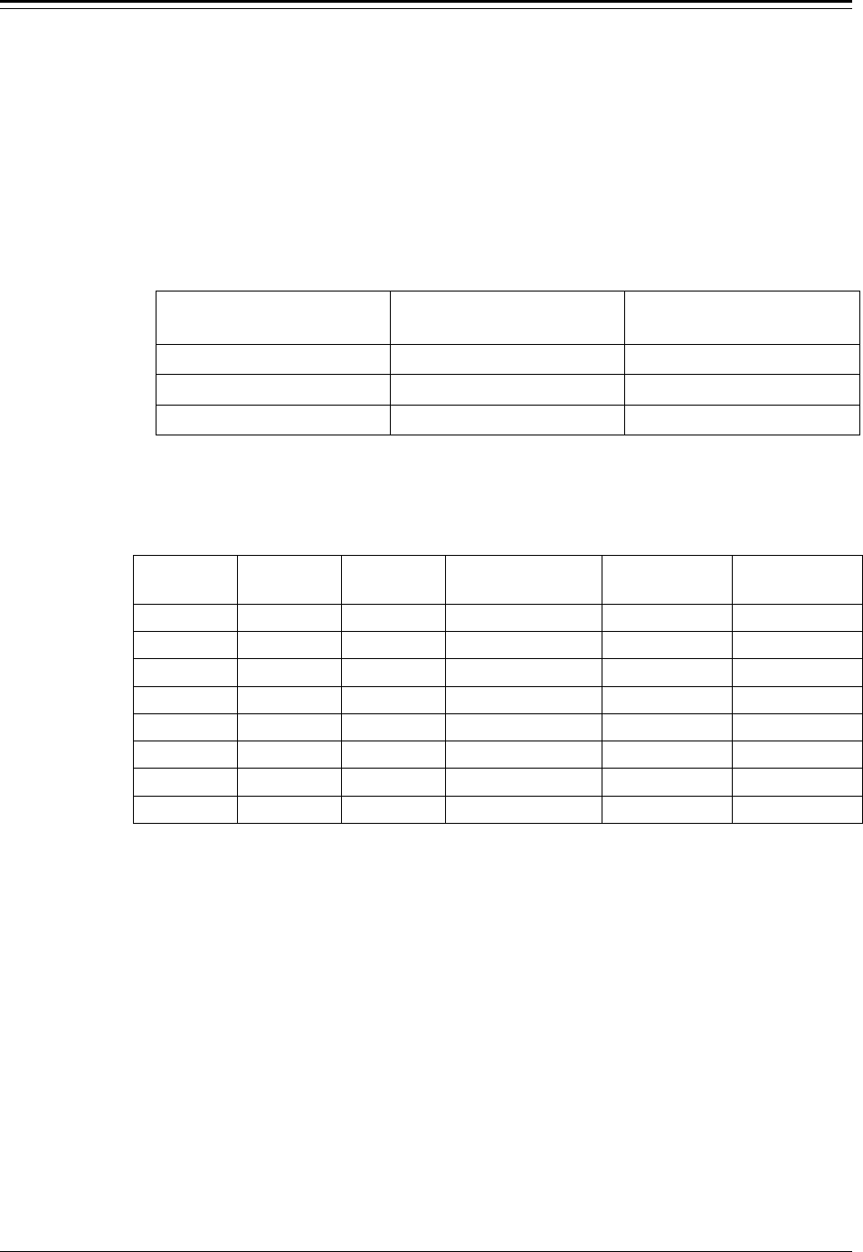
Chapter 5 Radar Fine Tuning Accu-Wave
5-28 TN Technologies
• Maximum level to be measured: 24.00 ft
• False Echo Management menu:
− Successive weighting factor (SWF): 0.5 (default)
− Bottom echo signal strength factor: 0.25
− Distance REF LINE to tank bottom: 24.00 ft
• Response Time, Lost Echo and Agitator Reject menu:
− range gate weighting factor (GWF): 5
Region Weighting Setup:
Region Number Region Boundary Weighting Factor
1 REF LINE – 11.00 ft 1.5
2 11.00 – 13.00 ft 2.0
3 13.00 ft – max distance 1.1
Tank Mapping Setup:
• Set to derate mapped echoes: 0.05 derating factor
Echo Report
echo
number distance
(ft) sig str Comment Combined
wtg factor modified
sig str*
1 24.75 1000 1.1 x 0.25 275
2 22.00 200 1.1 220
3 17.00 300 1.1 330
4 12.50 100 2.0 200
5 11.50 50 within range gate 2.0 x 0.5 500
6 9.00 150 1.5 225
7 7.50 1000 mapped 1.5 x 0.05 75
8 5.00 200 mapped 1.5 x 0.05 15
*The sig str reading from the echo report is weighted by the factors in the “Combined wtg
factor” column to obtain the “modified sig str” value before applying the 0.5 successive
weighting factor to select the “best echo.” In this example, echo number 5 would be
selected as the “best” candidate echo. (See “Echo Weighting Factors” on page 5-13.)

Accu-Wave Chapter 6 Cuurent Outputs, Relays, and Alarms
TN Technologies 6-1
Chapter 6 Current Outputs, Relays, and Alarms
This chapter covers the “Modify or reassign current output” menu (the “Current output”
menu) and the “Set up fault alarms or change process alarm assignments” menu (the
“Alarm” menu).
Current Outputs
Note: If your MeasureTech Accu-Wave does not have an I/O board with a current
output installed, the “Modify or reassign current output” menu will not be
displayed.
Use the “Current outputs” menu to
• specify which measurement should drive the current output
• implement correction factors on each current output
• define a current output hold value which is different from the default of 50% of
scale
Note: Measurements other than the primary measurement (level or distance)
must be set up in the “Set up additional measurements” menu (see
Chapter 4) before they can control a current output.
You can direct different measurements to the same current output, but one must be
assigned in normal output mode and the other must be in alternate output mode. The
current output can be switched from normal mode to alternate mode by executing a
command to switch when an alarm is triggered (see “Set up for Alarms to Execute
Commands” on page 6-4) or you can enter a command to switch modes (see “Common
Action Items” on page 7-2).
For example, if you were interested in monitoring a maximum level of 20 ft during one
portion of the process and a maximum level of 10 ft during another part of the process,
you could set up the measurements and current outputs as follows.
Set up measurement 1 (the primary measurement) as level and assign it to drive the current
output in normal mode with the maximum current output corresponding to 20 ft.
Also assign measurement 2 to the level measurement, but assign measurement 2 to drive
the current output in alternate mode with the maximum current output corresponding to 10
ft. Recall that the measurement value corresponding to the maximum current output is
entered in the measurement setup menus.
Note: It is good practice to make a list of the current output assignments as you
set them up, and keep the list available for future reference.

Chapter 6 Cuurent Outputs, Relays, and Alarms Accu-Wave
6-2 TN Technologies
“Modify or Re-assign Current Output” Menu
Display Comments
Modify or re-assign
current output↓↓
Other functions→→
Press ↓ to access “Current Output” menu items. Press
→ to scroll to other menus.
maximum current
output 20.00 mA
(4.000 to 20.00)
NEXT↓↓
The range for the maximum current output is from
the minimum current output (currently 4.000mA) to
20.00mA. The default value for the maximum current
output is 20.00mA.
minimum current
output 4.00 mA
(.0001 to 20.00)
NEXT↓↓
The range for the minimum current output is from
.0001mA to the maximum current output (currently
20.00mA). The default value for the minimum
current output is 4.000 mA.
Note: Entering a value of exactly 0.0 causes the
default value of 4.000mA to be used for the
minimum current output.
Note: If two or more measurements have been set up, the next two menu items
will be displayed. If a second current output is also installed, the next two
menu items will be repeated for “current out 2.”
Mea 1: ft level
is sent to current
out 1 in normal
mode. NEXT↓↓ CHANGE→→
Assign desired measurement to current output 1 in
the normal mode. Select from the primary
measurement and the measurements set up using the
“Additional measurements” menus.
Mea 1: ft level
is sent to current
out 1 in alternate
mode. NEXT↓↓ CHANGE→→
Assign a measurement to current output 1 in the
alternate mode. If system includes more than one
current output, additional entries will show up.
Note: If a second current output is installed, the next two menu items will be
displayed first for “current output 1” and then for “current output 2.”
correction factor
for current output
at maximum: 1.000
NEXT→→
Fine tune the maximum current output value to
correct for component and wiring variations. (The
maximum current output value is scaled by this
value.) This item is repeated for each current output
installed.
correction factor
for current output
at minimum: 1.000
NEXT→→
Fine tune the minimum current output value to
correct for component and wiring variations. (The
minimum current output value is scaled by this
value.) This item is repeated for each current output
installed.
current output
hold mode value
50.00 % of scale
NEXT↓↓
Enter desired value for mid-range hold value for the
current output. Value is entered as a percentage of the
maximum current output value. The default is 50%.

Accu-Wave Chapter 6 Cuurent Outputs, Relays, and Alarms
TN Technologies 6-3
Set Up Fault Alarms or Change Process Alarm Assignments
Note: If no relays are installed in your gauge, the “Set up fault alarms...” menu
will not be displayed initially. Use the “Special functions” menu (page 8-
19) to enable alarm related functions so you can set up a non-relay display
alarm or other indicator.
The ”Set Up Fault Alarms…” menu provides four submenus which allow you to:
• Set up alarms to execute commands
• Assign process alarms to monitor specific measurements
• Assign relays to warning and fault alarms
• Assign relays to mode alarms
Non-relay Alarms
If your gauge does not have relays installed, the various alarm setup options will not be
displayed in the menus. To enable display of the alarm setup menu options, you must go to
the “Special Functions” menus (page 8-19) and change the item “Do not enable alarm
related selections” to “Do enable.” You will then be able to assign any of the alarm
indicators with the exception of controlling a relay.
Alarm Types
Process alarms actions occur when a process measurement value (level, volume, etc.)
passes either the alarm set point or alarm clear point, that is, when the alarm is activated
or when the alarm clears. The default alarm indicator for process alarms is to control relay
number N, where N is the alarm number.
Fault and warning alarms alert you to potential problems with the operation of the gauge.
The fault and warning alarms are:
• system fault
• radar head fault
• waiting for echo
• echo is lost
• signal saturated warning
• current output maximum or minimum reached
Mode alarms provide information about the status of the gauge.
• holds are active
• alternate output in use
• alternate time constant
• keypad in use
• power has been off
Fault, warning, and mode alarms do not have a default assignment. In some cases, a
warning message is displayed. The status and history of alarms can be reviewed using the

Chapter 6 Cuurent Outputs, Relays, and Alarms Accu-Wave
6-4 TN Technologies
“view alarm status” and “view alarm history,” see “Diagnostics: System Test, Related
Items” on page 9-2.
Set up for Alarms to Execute Commands
Use the following procedure to set up alarms to execute commands:
1. Use the “Set up Alarms to Execute Commands” menu items (see table below) to
define up to 3 sets of alarm actions. Each alarm action set consists of a pair of
commands, one to be executed when an alarm is activated and one to be executed
when the alarm is cleared. Defining the alarm action set makes the command pair
available to assign to an alarm.
2. To assign a command action set to a process measurement alarm, you must have
set up the measurement (see Chapter 4) and have assigned an alarm to the
measurement (see page 6-5). Then the alarm action set will be added to the list of
alarm indicators in the “Set up Alarm” menu items.
3. To assign a command action set to a fault, warning, or mode alarm, use the menu
items described in the “Assign Relays to Fault, Warning and Mode Alarms”
section on page 6-6.
Note: Write down each of the command action sets as you specify them. Due to
the limited display space, the “alarm indicated by” selection in the “Set up
alarm” menu item can not display the full command name. The alarm
action sets are referred to as “#1 act on ALM action,” and so forth.
“Set up for Alarms to Execute Commands” Menu
Display Comments
Set up for alarms to
execute commands→→
NEXT↓↓
Menu subgroup heading. Press → to access menu
items, press ↓ to scroll to next “Alarms” menu
subgroup.
#1 act on ALM SET is
“Do nothing” command
Continue↓↓ Change→→
Press → to scroll through the list of commands. Select
the action (command) to be executed when alarm is
activated. Selecting a command other than “Do
nothing” makes action set #1 available for assignment
to specific alarm conditions.
#1 act on ALM CLR is
“Do nothing” command
Continue↓↓ Change→→
Select the command to be executed when the alarm
clears. Typically a command is selected to undo the
effects of the command executed when the alarm is
activated.
Note: The above two menu items are repeated for alarm action sets #2 and #3.
Once commands have been assigned to alarm action sets, these action sets
are available as alarm indicators along with controlling relays (if installed),
flahing the display, and zeroing the current output.

Accu-Wave Chapter 6 Cuurent Outputs, Relays, and Alarms
TN Technologies 6-5
Alarm Commands
The following commands can be assigned as alarm actions:
• do nothing
• hold current output at 50.00% of scale
• hold current output at maximum (normally 20 mA)
• hold current output at minimum (normally 4 mA)
• clear all holds
• disable range gate until re-capture
• stop data stream on port 1
• re–start data stream on port 1
• stop data stream on port 2
• re–start data stream on port 2
• show custom message on line 4
• stop custom message on line 4
• switch current output to alternate mode
• switch current output to normal mode
• switch display to alternate mode
• switch display to normal mode
• hold current output at zero mA
• save relay log data to NVRAM
• update data output to port 1, RS-232
• update data output to port 2, RS-485
Assign Alarms to Measurements
Use the “Assign alarms to measurements” menu to assign alarms to monitor specific
measurements. This menu item will only be displayed if you have set up one or more
measurements in addition to the primary measurement using the “Additional
measurements” menu (Chapter 4).
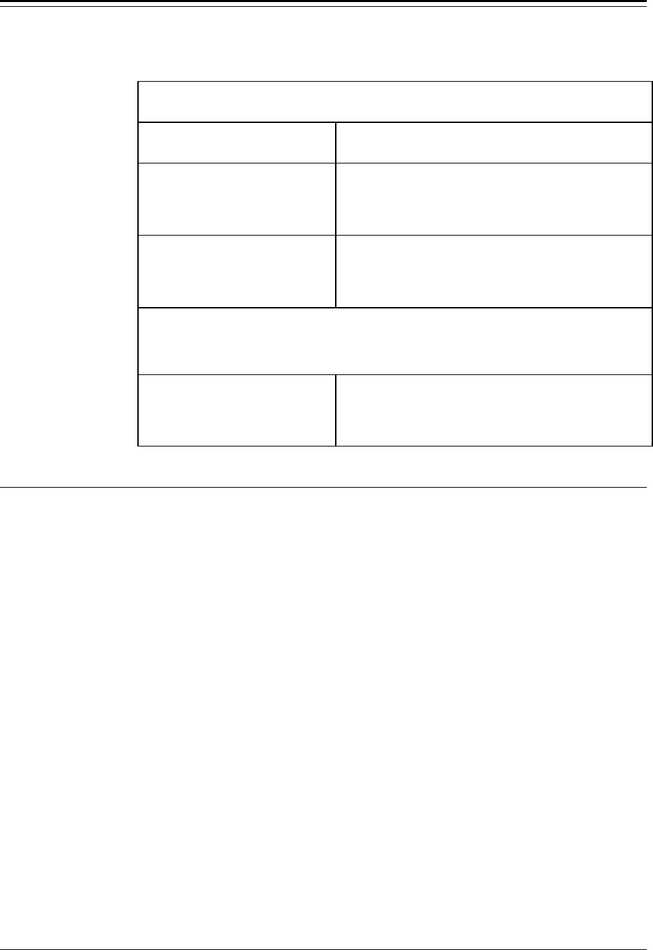
Chapter 6 Cuurent Outputs, Relays, and Alarms Accu-Wave
6-6 TN Technologies
By default all 16 alarms are assigned to the primary measurement, measurement 1.
“Assign Alarms to Measurements” Menu
Display Comments
Assign alarms to
measurements→→
NEXT↓↓
Menu subgroup heading. Press → to access menu
items, press ↓ to scroll to next “Alarms” menu
subgroup. Only displayed if you have set up one or
more additional measurements (other than primary).
#1 alarm monitors
measurement 1
ft level
Continue↓↓ Change→→
Press → to scroll through the list of measurements
that have been set up until the one you want appears.
Message on third line indicates the measurement type
corresponding to the measurement number.
Note: By default configuration, all 16 alarms are assigned to the measurement 1
(the primary measurement). Above menu item is repeated for alarms 2 – 15.
Press “EXIT SETUP” to save entries and return to the measurement display
if you do not want to assign more alarms.
#16 alarm monitors
measurement 1
ft level
Continue↓↓ Change→→
Scroll through the list of measurements that have
been set up until the one you want appears.
Assign Relays to Fault, Warning and Mode Alarms
Relays can be assigned to fault alarms, warning alarms and mode alarms using the menu
items shown in the table below. The “Assign relays to warning alarms and fault alarms”
menu items apply to warning and fault alarms, while the “Assign relays to mode alarms”
menu items apply to the mode alarms.
The “Assign relays…” menu headings are somewhat misleading as these menus are used
to assign any of the alarm indicators (controlling relays, flashing the measurement display,
zeroing current output, or executing a command) to the fault, warning, or mode alarms.

Accu-Wave Chapter 6 Cuurent Outputs, Relays, and Alarms
TN Technologies 6-7
Assign “Relays” to Warning Alarms and Fault Alarms
This menu assigns actions to indicate a warning alarm state, a system fault alarm or a
signal loss alarm.
“Assign Relays to Warning and Fault Alarms” Menu
Display Comments
Assign “relays” to
warning alarms and
fault alarms→→
NEXT↓↓
Menu subgroup heading. Press → to access menu
items, press ↓ to scroll to next “Alarms” menu
subgroup. For each of the following menu items,
press → to scroll through and select the desired alarm
indicator.
system fault
alarm indicated by
(Nothing)
NEXT↓↓ CHANGE→→
“System fault” can be caused by a radar head fault, a
signal processor failure, a write error to non-volatile
memory, or a memory checksum error.
Radar head fault
alarm indicated by
(Nothing)
NEXT↓↓ CHANGE→→
Caused by partial or complete loss of control signals
from radar head.
Waiting for echo
alarm indicated by
(Nothing)
NEXT↓↓ CHANGE→→
No echo is being received (within the range of
interest and above the minimum signal strength) but
the “lost echo” delay has not yet timed out. The signal
(if any) is outside of the acceptable range gate.
echo is lost
alarm indicated by
(Nothing)
NEXT↓↓ CHANGE→→
No echo is being received (within the range of
interest and above the minimum signal strength) and
the “lost echo” delay has timed out.
signal saturated
alarm indicated by
(Nothing)
NEXT↓↓ CHANGE→→
The signal strength of the strongest echo has
exceeded the maximum allowed level. If this problem
continues, increase the dielectric constant (page 5-2)
to reduce the gain applied to the microwave signal.
current max or min
alarm indicated by
(Nothing)
NEXT↓↓ CHANGE→→
Current output has reached the maximum or
minimum value.
←←Exit from:
Assign “relays” to
warning alarms and
fault alarms
Press ← to Exit from this menu subgroup.

Chapter 6 Cuurent Outputs, Relays, and Alarms Accu-Wave
6-8 TN Technologies
Assign “Relays” to Mode Alarms
This menu assigns actions (alarm indicators) to the mode alarms.
“Assign Relays to Mode Alarms” Menu
Display Comments
Assign “relays” to
mode alarms→→
NEXT↓↓
Menu subgroup heading. Press → to access menu
items, press ↓ to scroll to next “Alarms” menu
subgroup. For each of the following menu items,
press → to scroll through and select the desired alarm
indicator.
Hold(s) are active
alarm indicated by
(Nothing)
NEXT↓↓ CHANGE→→
One or more “holds” are active. See “Hold Action
Items” on page 7-4.
output on alt meas
alarm indicated by
(Nothing)
NEXT↓↓ CHANGE→→
The current output has switched to the alternate
measurement. See “Current Outputs” on page 6-1.
alternate time const
alarm indicated by
(Nothing)
NEXT↓↓ CHANGE→→
Keypad is in use
alarm indicated by
(Nothing)
NEXT↓↓ CHANGE→→
The transmitter keypad or a serial port is being used
to access the gauge’s setup menus. See “Security” on
page 9-1.
Power has been off
alarm indicated by
(Nothing)
NEXT↓↓ CHANGE→→
The gauge power has been off. Generally not a
concern unless there was an unexpected interruption
in power. Once saved, the gauge’s setup parameters
are preserved even when power is disconnected.
←←Exit from:
Assign “relays” to
mode alarms
Press ← to Exit from this menu subgroup.
Do / Do Not Show Relay Status
In addition to the four “Set up Fault Alarms,…” submenus, there is a menu item that
allows you to enable display of the relay status on the measurement display. If you select
“Do show relay status,” a message similar to “ 21 RELAY# ON” is displayed, indicating
that relay number 1 and number 2 are currently on. Only the number of the relays which
are currently on are shown in the relay status message.

Accu-Wave Chapter 7 Action Items
TN Technologies 7-1
Chapter 7 Action Items
The “Action Items” menu contains the most frequently used commands. Commands are
grouped by function into four menu subgroups.
• “Common action items” menu: use this menu to restart the system, erase all
entries, clear all holds, change mode, and zero relays.
• “Alarm action items” menu: use this menu to clear, acknowledge, disable, erase,
show history, end delays, and zero relays for all alarms.
• “Hold action items” menu: use this menu to clear, hold current output, set hold
mode value, scale, and set holds for distance, level and volume.
• “Serial port related action items” menu: use this menu to update set up and enable
serial ports.
When you execute a command, a message appears telling you that the command is being
executed.

Chapter 7 Action Items Accu-Wave
7-2 TN Technologies
Common Action Items
“Common Action Items” Menu
Display Comments
Common action items
(clear memory, etc)→→
NEXT↓↓
Press → to enter the “Common action items” menu.
Press ↓ to continue to next “Action Item” menu
subgroup.
System restart. Does
not affect user data
←←Exit this menu.
NEXT↓↓ EXECUTE CMD→→
Restarts system – erases temporary memory, but does
not affect user-entered setup data.
Erase all entries!!!
(except COMM setup)
←←Exit this menu.
NEXT↓↓ EXECUTE CMD→→
Erase all previously entered set up data. All settings
except for serial communication settings are reset to
factory defaults. Gauge will behave just like the first
time power was applied.
Clear all holds
(some now in effect)
←←Exit this menu.
NEXT↓↓ EXECUTE CMD→→
This item is only displayed when one or more holds
are in effect. See “Hold Action Items” on page 7-4.
Note: If more than three measurements are set up, the system assigns the “extra”
readouts to show up in “alternate mode” and the display toggles between
“normal” and “alternate” modes. The lowest-numbered measurements are
displayed at top of both normal and alternate mode displays depending on
available space.
Switch display to
alternate mode
←←Exit this menu.
NEXT↓↓ EXECUTE CMD→→
Displayed when more measurements are set up than
can be displayed at one time. Execute command to
stop display alternation, showing only the higher-
numbered readouts. Execute “Clear all holds”
command to resume display alternation.
Switch display to
normal mode
←←Exit this menu.
NEXT↓↓ EXECUTE CMD→→
Similar to “Switch … to alternate” item above. Stops
display alternation, showing only the lower-numbered
readouts. Execute “Clear all holds” command to
resume display alternation.
Switch current out
to alternate mode
←←Exit this menu.
NEXT↓↓ EXECUTE CMD→→
Displayed when a measurement has been assigned to
a current output in alternate mode, see page 6-1.
Execute command to switch to alternate current
output mode. Display will then read “Switch … to
normal mode.” Execute command again to switch
back to normal current out mode.

Accu-Wave Chapter 7 Action Items
TN Technologies 7-3
Alarm Action Items
“Alarm Action Items” Menu
Display Comments
Alarm action items
(View, clear, etc)→→
NEXT↓↓
Press → to enter the “Alarm action items” menu.
Press ↓ to continue to next “Action Item” menu
subgroup
view alarm status→→
NEXT↓↓
Press → to review all alarms currently in effect.
Includes process, warning, fault, and mode alarms
view alarm history→→
NEXT↓↓
Press → to review history of all alarms which have
occurred since the last “clear all alarms” command.
Includes process, warning, fault, and mode alarms.
Clear all alarms
←←Exit this menu.
NEXT↓↓ EXECUTE CMD→→
Acknowledge, then clear and reset all alarms. All
alarm actions are cleared, but the setup of the alarms
is not affected. Alarm actions are re-established when
the alarm is again activated.
Acknowledge
all alarms
←←Exit this menu.
NEXT↓↓ EXECUTE CMD→→
Acknowledge, but do not clear or reset alarms. All
alarm actions (relay, etc.) are cleared, but the actual
alarm remains activated. The alarm action is not re-
established until the alarm is cleared (by command or
change in process) and the alarm is again activated.
Disable all alarms
←←Exit this menu.
NEXT↓↓ EXECUTE CMD→→
Turns all alarms off until manually turned on. This
command causes the system to ignore alarms. After
executing this command, the display will read
“Enable all alarms.” Executing the command a
second time reinstates all alarms.
Erase all alarm action
assignments
←←Exit this menu.
NEXT↓↓ EXECUTE CMD→→
Erases entries for alarm assignments to relays,
command execution, display flash, and zeroing
current output. Executing this command returns all
alarm assignments to their defaults.
Note: The next two menu items are only displayed if “alarm delay times” have
been enabled in the “Special Functions” menu (page 8-19) and a delay time
for alarm activation or alarm clear has been entered for one or more alarms.
end alarm
delay command
←←Exit this menu.
NEXT↓↓ EXECUTE CMD→→
If an alarm condition is true but alarm activation is
being delayed because the alarm delay time has been
set, this command cancels the delay time and the
alarm will be activated.
end un-alarm
delay command
←←Exit this menu.
NEXT↓↓ EXECUTE CMD→→
If an alarm clear condition is true but the alarm clear
is being delayed becauese the alarm clear (un-alarm)
delay time has been set, this command cancels the
delay time and the alarm will be cleared.

Chapter 7 Action Items Accu-Wave
7-4 TN Technologies
Hold Action Items
“Hold Action Items” Menu
Display Comments
“Hold” action items
(Hold reading, etc)→→
NEXT↓↓
Press → to enter the “Hold action items” menu. Press
↓ to continue to next “Action Item” menu subgroup.
Clear all holds
(none now in effect)
←←Exit this menu.
NEXT↓↓ EXECUTE CMD→→
Execute this command to clear all holds (if any holds
are in effect).
Hold current output
at max (20.00 mA)
←←Exit this menu.
NEXT↓↓ EXECUTE CMD→→
Holds all current outputs at the value entered for the
maximum current output.
Hold current output
at min (4.000 mA)
←←Exit this menu.
NEXT↓↓ EXECUTE CMD→→
Holds all current outputs at the value entered for the
minimum current output.
Hold current output
at zero mA
←←Exit this menu.
NEXT↓↓ EXECUTE CMD→→
Holds all current outputs at 0.0 mA.
Current output
hold mode value
50.00% of scale
NEXT↓↓
Enter value in % for the mid-range current output
hold value. Default value is 50.00%.
Hold current output
at 50.00% of scale
←←Exit this menu.
NEXT↓↓ EXECUTE CMD→→
Press → to execute command to hold current output at
the mid-range value specified in the previous menu
item.
Level hold mode
value
0.000 ft level
NEXT↓↓
Enter the hold value for the primary measurement
(level or distance). This value is also used as the “lost
echo value” when “go to hold value” is selected as the
“echo loss mode.” See page 5-8.
Hold level at
0.000 ft level
←←Exit this menu.
NEXT↓↓ EXECUTE CMD→→
Press → to hold primary measurement value at the
hold value specified in the previous menu item. After
executing command, display changes to read “Clear
holds→.” Press → to clear the hold level command.

Accu-Wave Chapter 7 Action Items
TN Technologies 7-5
“Hold Action Items” Menu (cont.)
Display Comments
level hold value
0.000 cm
{for abs level test}
{cmd 154} NEXT↓↓
Enter hold value for level used to test the absolute
level. Execute level hold using the next menu item.
Hold level at
0.000 ft level
←←Exit this menu.
NEXT↓↓ EXECUTE CMD→→
Press → to execute command to hold primary
measurement value at the hold value specified in the
previous menu item. Use “Clear all holds” command
(first item in this table) to clear.
Volume hold mode
value 0.000 cu ft
NEXT↓↓
Only displayed if “tank volume setup” has been
completed. Enter the volume hold value.
Hold Volume at
0.000 cu ft
←←Exit this menu.
NEXT↓↓ EXECUTE CMD→→
Press → to execute command to hold volume
measurement value at the hold value specified in the
previous menu item.

Chapter 7 Action Items Accu-Wave
7-6 TN Technologies
Serial Port Related Action Items
“Serial Port Related Action Items” Menu
Display Comments
serial port related
action items→→
NEXT↓↓
Press → to enter the “Hold action items” menu. Press
↓ to return to main heading for the “Action Items…”
menu group
update data output
to port 1, RS232
←←Exit this menu.
NEXT↓↓ EXECUTE CMD→→
Sends a data set (as defined by serial transmit setup or
default) to RS-232 port.
update data output
to port 2, RS485
←←Exit this menu.
NEXT↓↓ EXECUTE CMD→→
Sends a data set (as defined by serial transmit setup or
default to RS-485 port.
clear flgs-buff
RS232
←←Exit this menu.
NEXT↓↓ EXECUTE CMD→→
[Service only item.]
clear flgs-buff
RS485
←←Exit this menu.
NEXT↓↓ EXECUTE CMD→→
[Service only item.]
dump setup data
via port 1, RS232
←←Exit this menu.
NEXT↓↓ EXECUTE CMD→→
Available only if “Serial dump items” have been
enabled in the “Special Functions” menu. This item
allows the gauge’s current setup to be dumped to the
RS-232 serial port. Requires special purpose program.
dump setup data
via port 2, RS485
←←Exit this menu.
NEXT↓↓ EXECUTE CMD→→
Same as previous item, except for RS-485 port.
Requires TNComm software or other special purpose
program.
retrieve setup data
via port 1, RS232
←←Exit this menu.
NEXT↓↓ EXECUTE CMD→→
Available only if “Serial dump items” have been
enabled in the “Special Functions” menu. This item
retrieves the gauge’s setup data dumped to the RS-
232 serial port using the “dump setup data”
command. Requires special purpose program.
retrieve setup data
via port 2, RS485
←←Exit this menu.
NEXT↓↓ EXECUTE CMD→→
Same as previous item, except for RS-485 port.
Requires TNComm software or other special purpose
program.

Accu-Wave Chapter 8 Serial Ports, Contact Inputs & Special Fcts
TN Technologies 8-7
Chapter 8 Serial Ports, Contact Inputs, and
Special Functions
This chapter describes the menu items under the “Set up serial ports, contact INPUT, or
Special functions” menu. This menu group includes menu subgroups for the following
gauge functions.
Configure the RS-232 (port 1) and RS-485 (port 2) serial ports for communicating with
computer terminals and printers and set up the data stream transmission parameters.
Assign commands to execute when the contact closure input(s) are opened or closed.
Set up and control the gauge’s “Special functions” – a variety of useful, but specialized
menu items for controlling the operation of relays, specifying what is shown on the
measurement displays, and enabling the “service only” menu items.
Serial Ports
The gauge offers both an RS-232 single–drop (port 1) and an RS-485 multi–drop (port 2)
serial interface. Each port provides independent access to the gauge's measurement and
software functions, and both ports can be used simultaneously. For example, the system is
able to communicate with a host computer on one port, while sending data to a printer on
the other port.
The remote device (host computer or terminal) can enter or recall setup data and enter
commands. Interactive communications on either port emulate the integral keypad on the
transmitter. The gauge interprets the received characters as keypad entries.
By default, the gauge’s serial interface emulates the transmitter’s integral display and
keypad when you connect a remote ANSI terminal or a PC with ANSI terminal emulation
software to the RS-232 port (or to the RS-485 port using an RS-232 to RS-485 adapter).
Alternately, you can connect a TN Model 9733 Hand Held Terminal to the RS-485 port.
The RS-485 port supports multi-unit “party line” communications for a maximum of 32
units. Each unit must be assigned a unique unit identification number so it can be
addressed individually. A unit assigned the default unit number of zero will behave as if it
is the only unit in use.
TN Technologies offers TNComm software for your PC that lets you set up and monitor
daisy-chained RS-485 gauges, download or upload gauge setups, and emulate a Model
9733 Hand-Held Terminal.
Terminal Types
The menus allow you to configure the RS-232 (Port 1) and RS-485 (Port 2) ports to
communicate with the following devices.

Chapter 8 Serial Ports, Contact Inputs & Special Fcts Accu-Wave
8-8 TN Technologies
ANSI terminal: The gauge sends ANSI escape sequences for screen and cursor control
which are supported by ANSI terminals and by most PC-based communication packages.
This setup allows full access to the gauge menu system from the terminal. The arrow keys
on the terminal keypad behave in the same fashion as the intergral keypad on the
transmitter. The “X” or “x” keys on the remote computer or terminal correspond to the
“EXIT SETUP” key on the transmitter’s keypad.
VT100 terminal: This setup supports VT100 terminals and is similar to the ANSI terminal
setup.
Hand–Held terminal: This configuration supports the TN Hand Held Terminal (Model
9733) or the TNCOMM software emulation of the the Hand Held terminal.
Printer: This mode supports serial output to most printers. The ANSI screen–control
escape sequences are not available because they might be misinterpreted as printer set up
commands. Data is transmitted at the update interval you select in the “Set up port…”
menu items described below, or whenever you execute the “update data output” action
item (see page 7-6). This mode is output only, so the menu system is not available.
Blind mode: This is a special mode which supports access to the gauge via a user-written
program or script. The menu system is not available, rather the hexadecimal version of the
direct entry keyboard codes are used to set parameters. The gauge unit will echo a “>”
character (ASCII code 62) if the code is understood, otherwise it sends a “<” character
(ASCII code 60). This mode supports user-written scripts from within a terminal
emulation communications package to automate a setup or a data monitoring procedure.
Serial Port Related Menus
There are four menu subgroups used to set up and control the serial ports, two for the RS-
232 port and two for the RS-485 port. When you make entries for the parameters, the
actual port operation will not change until you save the entries (press “EXIT SETUP” to
save entries and return to the measurement display).
The serial port communication settings are configured using the “Modify Port 1 (RS232)
Configuration” and the “Modify Port 2 (RS485) Configuration” menus. The “Set up Port
1 (RS232) Data Transmission” and “Set up Port 2 (RS485) Data Transmission” menus
control the selection, formatting, and transmission of measurement data to the terminal or
printer.
The RS-232 and RS-485 configuration menus are very similar and the menu items
described in the following tables apply to both ports, except where noted.
Modify Port 1 RS232 (Port 2 RS485) Configuration Menus
Use this menu to set up the baud rate and other communication parameters for each port.
The RS-232 menu items will display “RS232” or “Port 1 RS232” while the RS-485 menu
items will display “RS485” or “Port 2 RS485.” The necessary configuration information
for your communication device should be found in the user’s manual for the device.

Accu-Wave Chapter 8 Serial Ports, Contact Inputs & Special Fcts
TN Technologies 8-9
“Modify Port 1 RS232 (Port 2 RS485) Configuration” Menu
Display Comments
Modify Port 1 RS232
configuration→→
(baud rate, parity)
NEXT↓↓
Press → key to access the “Modify port configuration”
setting menus.
Do not disable
port 1 RS232
Change to “Do”→→
Continue as is.↓↓
Turns port on or off. Change to “Do” if you need to
temporarily disable the RS-232 port.
unit number of this
gauge (0 to 32) 0
(Should be 0 if not
party line.) NEXT↓↓
Applies to Port 2 RS-485 only. Default value is 0 for
single unit operations. Assign unit id number (1-32)
for party line communications. Master gauge (unit) is
normally assigned to be unit 1 for party-line comm’s.
interface RS232 with
ANCI terminal
(or PC emulation)
Continue↓↓ Change→→
Interface RS-232 with the following serial devices:
ANSI terminal (or PC emulation)
VT100 terminal (or PC emulation)
Handheld terminal
Printer
“Blind” mode (no key echo, menu or words)
port 1 RS232
9600 baud
Continue↓↓ Change→→
Select baud rate.
Valid choices are 1200, 2400, 4800, or 9600 bps.
port 1 RS232 uses
7 bit word
Change to “8”→→
Continue as is.↓↓
Select word length - 7 or 8 bit word lengths are
supported.
port 1 RS232 uses
even parity
Change to “none”→→
Continue as is.↓↓
Select parity - even parity or none are supported.
Do send LineFeed
with CR for NewLine
Change to “Do not”→→
←←Exit port 1 setup.
“Do send” causes a LINEFEED (ASCII char 10) to be
sent after a CARRIAGE RETURN (ASCII char 13)
for NEWLINE. “Do not” suppresses the LINEFEED
after a CR. Some serial printers expect CR only while
others expect CR + LF.
Data Transmission (Data Streaming)
When a port is set up for data streaming (continuous transmission of readings), the system
sends a readout update on a regular basis. This update interval can be varied from 1
second to 9999 seconds between updates. The update data can include the readouts from
any or all of the measurements that have been set up (measurements 1 through 8). Data

Chapter 8 Serial Ports, Contact Inputs & Special Fcts Accu-Wave
8-10 TN Technologies
can be formatted for various terminals (CRTs), printer presentations, or for host
computers.
Data streaming on a party-line (RS-485 multiple units) is automatically suspended when
you send the “SLEEP” command, and is normally suspended when you “CONNECT” to
any unit on the party line. You can tell a unit to “output while in connect” using the “Set
up Port …” menus (described below) so the unit will continue to data stream, except while
you are in the menu system. A unit with a unit number of zero will automatically “output
while in connect.”
A reading is a measurement such as level or volume. A data set is all of the readings being
sent by a particular unit. By default, a NEWLINE is sent after each reading. A HOME
and a CLEAR are sent after each set. This causes the data to update at the same place on
the screen.
Set up Port 1 RS232 (Port 2 RS485) Data Transmission
This menu controls the selection, formatting, and transmission of real-time measurement
data to a serial device via the RS-232 (RS-485) ports.
“Modify Port 1 RS232 (Port 2 RS485) Configuration” Menu
Display Comments
Set up port 1 RS232
data transmission→→
(data streaming)
NEXT↓↓
Press → key to access the “Set up port…” menus to
configure data transmission (data streaming).
←←Exit from: RS232
data transmit setup.
Continue↓↓
Data Transmit HELP→→
Press → to access the “Data Transmit Help” screens.
Press ↓ to continue with setup.
Do not inhibit RS232
data streaming.
Change to “Do”→→
Continue as is.↓↓
Turns data streaming on or off. If you inhibit data
streaming (select “Do”), data transmission stops until
you again select “Do not.”

Accu-Wave Chapter 8 Serial Ports, Contact Inputs & Special Fcts
TN Technologies 8-11
“Modify Port 1 RS232 (Port 2 RS485) Configuration” Menu (cont.)
Display Comments
The following menu item is repeated for measurement (1-8) which has been set up.
Do not send meas 1
ft level to
RS232 port.
NEXT↓↓ CHANGE→→
Similar menu item is displayed for each measurement
number you have set up. You can enable or disable
the transmission of the data for each measurement
individually.
Do not transmit data
in “packet” format
Change to “Do”→→
Continue as is.↓↓
Select “Do” to enable transmission of data in packets
as described on page Error! Bookmark not defined.,
or select “Do not” to transmit data in non-packet
format as described on page 8-12.
Do not data stream
in “connect” mode
Change to “Do”→→
Continue as is.↓↓
Applies to RS-485 party-line communications only.
Select “Do” to have the gauge continue data
streaming while the gauge is in “connect” mode. See
“Party–Line Communications” on page 8-15.
This is a slave
unit (xmit control).
Change to “master”→→
Continue as is.↓↓
Applies to RS-485 party-line communications only.
Specify whether this gauge is a slave or the master for
party-line communications. See “Party–Line
Communications” on page 8-15.
Set up data format.→→
NEXT↓↓
Menu subgroup header. Press → to access data format
menu items. Format options depend on selection of
packet or non-packet data transmission above. See
page Error! Bookmark not defined. for packet data
format menu items and see page 8-12 for non-packet
data format menu items.
Set up header- Form
feed, message, etc
{RS232}→→
NEXT↓↓
Menu subgroup header. Only displayed if non-packet
data transmission has been selected. See page 8-14
for a description of menu options.
window code, 0 must
be >= 33 and must
= window code in all
other units. NEXT↓↓
Applies to RS-485 party-line communications only.
The value entered must be the same for all units and
must be at least as large as the largest “must be >=”
value displayed for any unit. See page 8-15.
Highest unit number
in group 8
NEXT↓↓
Applies to RS-485 party-line communications only.
Only appears in setup for Master unit. Enter the
highest unit number assigned to any gauge on the
party-line. Maximum number of units is 32.
port 1 RS232 update
time 0 sec
NEXT↓↓
Set the time (seconds) between updates. If zero (0) is
entered, the gauge waits for an “update data output”
command for the serial port (see “Serial Port Related
Action Items” on page 7-6).
For RS-485 party-line operations: Set update time to
zero (0) for slave units. For the master unit, set time
(sec) between update cycles. See page 8-15.

Chapter 8 Serial Ports, Contact Inputs & Special Fcts Accu-Wave
8-12 TN Technologies
Set Up Data Format (Non-Packet Text Data) Menu
The “Set Up Data Format” menu items for non-packet data are displayed if “Do not
transmit data in packet format” is selected in the “Set up port … transmission data” menu.
These menu items establish the formatting used for non-packet text transmission (for
example, labeling, tabulation, and pagination) for measurements sent to a terminal or
printer.
In the following menu items, a reading refers to a particular measurement such as level or
volume. A data set refers to all the readings being transmitted by a particular unit (gauge).
By default, a NEWLINE is sent after each reading. A HOME and a CLEAR are sent after
each data set. This causes the data to update at the same place on the screen.
The “Set up data format” menus for non-packet data are identical for the RS-232 and the
RS-485 ports except for the references to the port number. The table below shows the
menu items as they appear for the RS-232 port.
“Set Up Data Format (Non-Packet Data)” Menu
Display Comments
Set up data format.→→
NEXT↓↓
The following non-packet format menu items are
displayed if “Do not transmit … packet format” was
selected in the “Set up port … data transmission”
menus. The menu items are identical for the RS-232
and RS-485 ports.
Do not put meas num
before each reading.
Change to “Do”→→
Continue as is.↓↓
Select “Do” to put the measurement number (1 to 8)
before each reading.
Do send NEWLINE
after each reading.
Change to “Do not”→→
Continue as is.↓↓
“Do” sends a logical NEWLINE after each reading.
“Do not” suppresses the NEWLINE.
Do send units
with each reading.
Change to “Do not”→→
Continue as is.↓↓
“Do” sends the measurements unit string (ft level, sig
str, cu M, etc). “Do not” suppresses the units string.
Do not put unit num
before each reading.
Change to “Do”→→
Continue as is.↓↓
Applies to RS-485 party line communications only.
Sends the gauge unit number with each reading.
Do not put TAB
after each reading.
Change to “Do”→→
Continue as is.↓↓
Change to “Do” to append a TAB (ASCII char 9)
after each reading. Useful for sending columnar data
to a printer.

Accu-Wave Chapter 8 Serial Ports, Contact Inputs & Special Fcts
TN Technologies 8-13
“Set Up Data Format (Non-Packet Data)” Menu (cont.)
Display Comments
Do CLEAR & HOME
before each data set.
Change to “Do not”→→
Continue as is.↓↓
Sends an ANSI clear/home escape string after data
set.
Do not send NEWLINE
after each data set.
Change to “Do”→→
Continue as is.↓↓
Change to “Do” to send logical NEWLINE after
transmission of a gauge’s data set.
Do not send user msg
before each data set.
Change to “Do”→→
Continue as is.↓↓
Change to “Do” to send a custom (user-defined)
message before each dataset.
Do not put unit num
before each data set.
Change to “Do”→→
Continue as is.↓↓
Applies to RS-485 party line communications only.
Change to “Do” to send the gauge unit number before
transmission of each gauge’s data set.
Set up custom
data set messages
{RS232}→→
NEXT↓↓
Displayed if “Do send usr msg” was selected above.
Menu is similar to “Setting up Custom Units
Messages” on page 8-20 and uses the same message
data base.
port 1 (RS232) start
readout at screen
row 0
NEXT↓↓
Sends ANSI command to position readout start at a
specifed row number. Not available in blind, printer,
or hand-held terminal modes.
Port 1 (RS232) start
readout at screen
column 0
NEXT↓↓
Sends ANSI command to position readout start at a
specifed column number. Not available in blind,
printer, or hand-held terminal modes.
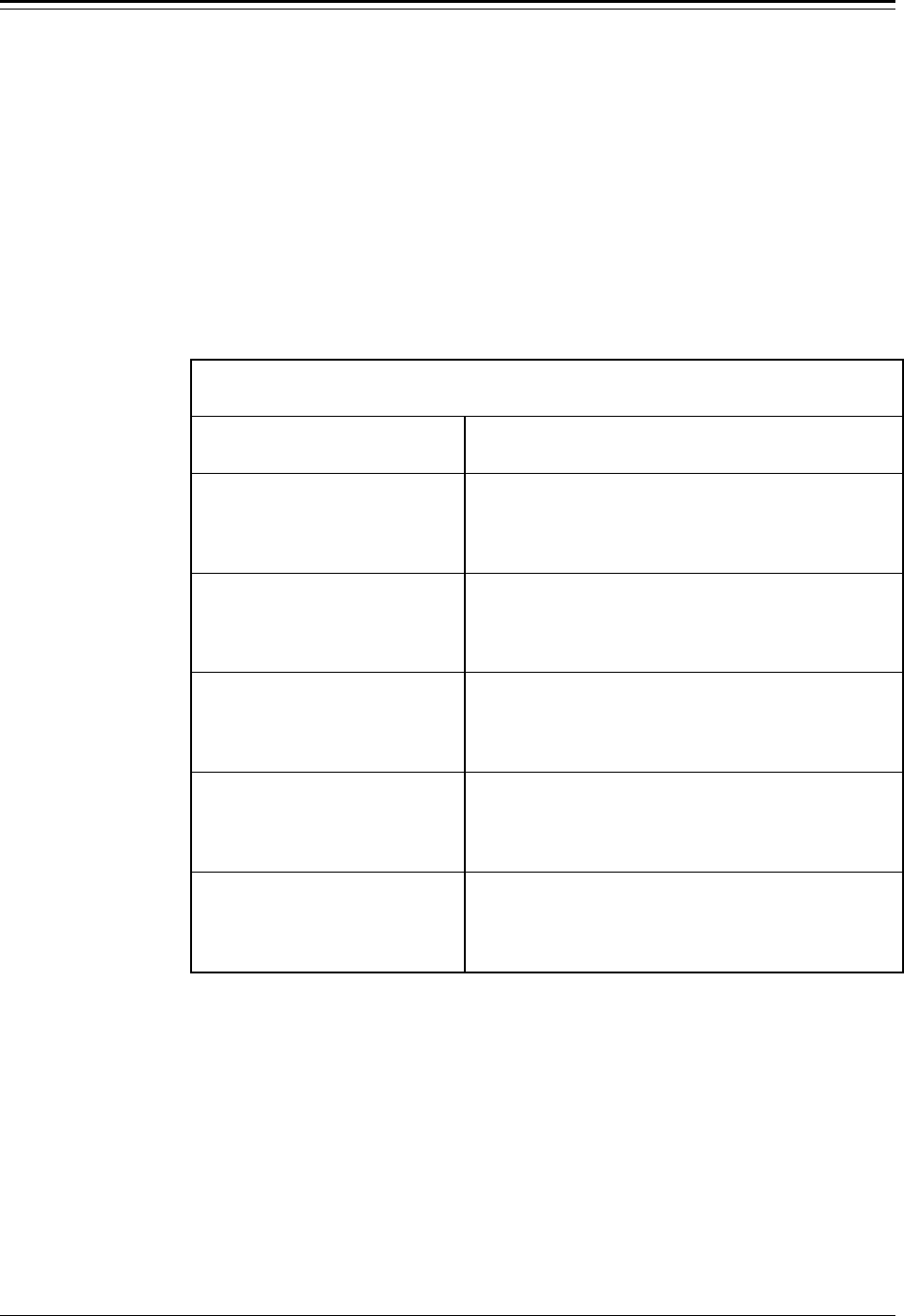
Chapter 8 Serial Ports, Contact Inputs & Special Fcts Accu-Wave
8-14 TN Technologies
Setup Header, Form Feed, and Message
This menu subgroup is only displayed when “Do not transmit data in packet format” is
selected in the “Set up port … data transmission menu.” These menu items allow you to
set up formatting information such as headers and form feeds. These items are most often
used for formatting data to be sent to a printer.
These menu items are identical for the RS-232 and RS-485 ports, except for references to
the specific port. The table below shows the menu items as they are displayed for the RS-
232 port.
“Set up Header, Form Feed, Message, etc.” Menu
Display Comments
Set up header- Form
feed, message etc
{RS232}→→
NEXT↓↓
This menu subgroup is available if “Do not transmit
… packet format” was selected in the “Set up port …
data transmission” menus. The menu items are
identical for the RS-232 and RS-485 ports
Send header every
0 data sets
(0 disables header)
(RS232) NEXT↓↓
Enter integer value “N” to send a header every “N”
data set transmissions from a gauge. Enter 0 to
disable the header.
Do not form-feed
before header, RS232
Change to “Do”→→
Continue as is.↓↓
Change to “Do” to send a form-feed (ASCII char 12)
before each header. Useful for grouping datasets on
separate pages.
Do not add message
to header, RS232
Change to “Do”→→
Continue as is.↓↓
Change to “Do” to add a custom message to header.
Set up serial
header message
(RS232)
NEXT↓↓
Displayed if “Do send add message to header” was
selected above. Menu for setting up header message is
similar to “Setting up Custom Units Messages” on
page 8-20 and uses the same message data base.

Accu-Wave Chapter 8 Serial Ports, Contact Inputs & Special Fcts
TN Technologies 8-15
Party–Line Communications
This section describes various aspects of setting up and using party-line communications
for multiple gauges.
Setting up a Party-Line
To set up party-line communications from the local keypad and display of each gauge on
the party-line, use the following procedure.
1. Wire all units to the RS-485 common lines as per the wiring instructions in the
Accu-Wave Installation and Maintenance Manual provided with your gauge.
2. For each unit, ensure the “Modify port …” menu communication settings is the
same (baud rate, parity, and handshake). Assign each gauge a unique non–zero
unit number. See page 8-8.
3. In the “Set up port … data tranmission” menu (page 8-10), set up the desired RS-
485 measurement selections, data formats, user messages, etc., for each unit.
After completing the data transmission setup, write down the “must be >=” value
displayed in the “window code” menu item. This is the minimum window code
required to transmit the data set for a particular gauge.
4. Using the “Set up port … data transmission” menu, configure the “master” unit
as follows. (The master unit is usually assigned the lowest unit number, typically
unit #1.)
− Specify that this unit is the master unit.
− Set the window code to be greater than or equal to the largest of the “must be
>=” window code values found for all of the units in step 3.
− Specify an appropriate RS-485 update time (see the next section, “Master
Update Time.”
5. Using the “Set up port … data transmission” menu, configure each of the “slave”
units as follows:
− Specify that the unit is a slave.
− Specify the same (largest) value for the window code as used for the master
unit in step 4.
− Specify that the RS-485 update time is zero (0).
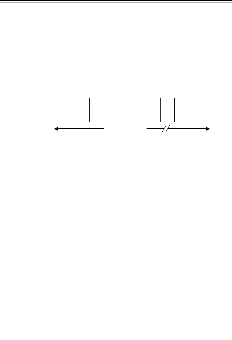
Chapter 8 Serial Ports, Contact Inputs & Special Fcts Accu-Wave
8-16 TN Technologies
Master Update Time
Gauges on a party–line transmit their data following the timing diagram shown in Figure
8.1. All of the gauges wait for the master unit to transmit a “sync” character (Ctrl-V,
ASCII 22). The master gauge transmits this synch character once per the update time
interval which is specified in the “Set up port … data transmission” menu.
Each gauge (including the master) counts off equally spaced time intervals based on the
window code (set identically for all of the gauges). When the current “window” interval
corresponds to a gauge’s unit number, that gauge transmits its data.
Start (sync character sent)
Unit 1 Unit 2 Unit 3 ...
Unit N
Window 1 Window 2 Window 3 ...
Window N
Figure 8.1 Party–Line Transmission Timing (Number of units, N ≤≤ 32)
For this data transmission scheme to work, two constraints must hold:
− Each slave unit must be programmed with the same window length, window
code, since equal spacing is assumed.
− The update time interval specified in the “Set up port … data transmission”
menu of the master unit must be greater than or equal to the combined
transmit time of the network. The minimum update interval required is given
by the following formula.
Update time = Largest window code x Largest Unit Number x 0.06 sec
Party–Line Modes
The party line has three distinct modes of operation, Unconnected, Connected, and Sleep.
Normally, the party line operates in the Unconnected mode.
A unit in Unconnected mode only responds to:
− a connect ESCAPE sequence with the proper unit–number suffix
− a command code with the proper unit–number suffix
− an all units SLEEP Command
− an all units WAKEUP Command
− a data streaming sync character
Otherwise, the unit sends updates at regular intervals as specified in the setup.
Window Time

Accu-Wave Chapter 8 Serial Ports, Contact Inputs & Special Fcts
TN Technologies 8-17
When a unit is in “Connect” mode, the unit’s setup menus can be accessed (if not in Blind
or Printer mode) and the unit will continue to send updates if “Do data stream in connect
mode” has been enabled. Connect mode is exited when a valid DISCONNECT command
is received.
A unit in Sleep mode will not respond to anything except a valid WAKEUP Command.
Party-Line Commands
Some useful escape codes are:
ESC [ Z# uu CONNECT Command. (uu = unit number, e.g., 01).
ESC O Q DISCONNECT Command
ESC X C SLEEP Command (ANSI)
ESC X D WAKEUP Command
ESC X 1 CONNECT Acknowledge (gauge sends this to acknowledge the
CONNECT command)
ESC X 2 Acknowledge DISCONNECT Command
ESC O V ID REQUEST Command
ESC X 4 ID REQUEST TERMINATED Command
ESC [Yuu;cc;vvdd POLLING Command,
where
uu = unit number (in hex) on party line
cc = command (in hex)
vv = unit number + 3 (in hex)
dd = command number +3 (in hex)
Presently, only three “cc” command values are supported:
86 – Single Data Stream Update on RS-485
8B – Download NVRAM contents to PC on RS-485
8D – Upload NVRAM contents to gauge
Example:
ESC [Y01;86;0489 sends the “Single Update” command to Unit 1.
Party-Line Limitations
The RS-485 party-line uses half-duplex communications. That is, only one system can
send information at any given time. For instance, if you are entering data during the time
window for a gauge to send its output, garbled characters may result. This occurs mainly
when the gauge’s menu system is being accessed in Connect mode. In this circumstance,
you should verify that the gauge received the correct setup information before continuing.

Chapter 8 Serial Ports, Contact Inputs & Special Fcts Accu-Wave
8-18 TN Technologies
The party-line also behaves erratically when more than one device issues synch characters.
This can happen if there is more than one master on the link, or if synch characters are sent
from a terminal or PC.
Data streaming has to be explicitly turned off in the “Set up port 2 RS485 data
transmission” menu. Deselecting all measurements from data streaming will not inhibit
data streaming. Rather, the gauge will send a default update with all measurements, escape
string positioning, and the “For setup, ...” message. This default update is intended to
appear after a complete NVRAM erasure (i.e., performing a CMD 74), when data
streaming has not yet been configured. Also, the data formatting and update time menus
will not be available until at least one measurement is selected.
Contact Inputs
You can assign commands to be executed based on a user-provided contact input open or
close. The following menu items are available for each contact closure input installed in
your gauge.
Note: If you do not have a current I/O board installed, you will not see the
“Contact closure inputs” options.
“Assign Commands to Execute on Contact Open/Close” Menu
Display Comments
Do nothing command
executed by closing
switch 1. Use↓↓ Chg→→
Press → to scroll through the list of commands until
the one you want is displayed. Commands include,
hold current output at max/min, clear all alarms,
clear all holds, etc.
Do nothing command
executed by opening
switch 1. Use↓↓ Chg→→
Press → to scroll through the list of commands until
the one you want is displayed.Typically, select a
command to reverse the effect of the contact close
command.
Note: These items are repeated for all the contact closure inputs that are installed.

Accu-Wave Chapter 8 Serial Ports, Contact Inputs & Special Fcts
TN Technologies 8-19
Special Functions
“Special functions” Menu
Display Comments
Do not enable alarm
related selections
Change to “Do”→→
Continue as is.↓↓
Displayed if no relays are installed. Change to “Do”
to enable the alarm-related menu selections
throughout the setup menus.
Do not enable alarm
relay delay times.
Change to “Do”→→
Continue as is.↓↓
Only displayed if relays are installed. Change to “Do”
to enable relay alarm delay time entries in menus
which set up process limit alarms.
Do not make relay
latching available
Change to “Do”→→
Continue as is.↓↓
Only displayed if relays are installed. Change to “Do”
to enable relay latch mode entries in menus which set
up process limit alarms.
Do not disable “For
setup”, etc. display
Change to “Do”→→
Continue as is.↓↓
Change to “Do” to suppress the message on line 4
(warnings and setup direction) of the normal readout.
This allows all four lines to be used for measurement
readouts.
Do not show relay
status on readout.
Change to “Do”→→
Continue as is.↓↓
Change to “Do” to display relay status on
mesaurement display. The numbers of the relays
currently turned on are displayed along with the
normal measurement readouts.
Do not disable
display of fault msg
Change to “Do”→→
Continue as is.↓↓
[Service only item.]
Change to “Do” to disable display of system fault
messages.
Do not disable
dynamic tracking
Change to “Do”→→
Continue as is.↓↓
Leave this item set to “Do not” so that dynamic
tracking remains enabled.
Dynamic tracking
threshold 0.000 f
(if 0, assumes half
range gate) NEXT↓↓
[Service only item.]
Controls dynamic tracking threshold. Typically leave
this value set at 0.0, so default threshold (half range
gate) is used.
Do not disable
“sig str” readout
Change to “Do”→→
Continue as is.↓↓
Change to “Do” to disable display of signal strength.
This will make display space (one line) available for
another readout.

Chapter 8 Serial Ports, Contact Inputs & Special Fcts Accu-Wave
8-20 TN Technologies
“Special functions” Menu (cont.)
Display Comments
Do not enable user
defined (UD) units.
Change to “Do”→→
Continue as is.↓↓
Change to “Do” to enable user defined units option in
the various “Select Units” menu items.
Note: Enabling the “Service only items” causes additional items to show up in
various “Radar Fine Tuning” submenus as well as in other setup menus.
Do not enable
service only items.
Change to “Do”→→
Continue as is.↓↓
Causes additional “service only” setup items to show
up in several areas. Default condition is “do not.”
Do enable
serial dump items.
Change to “Do not”→→
Continue as is.↓↓
Change to “Do not” to disable commands to dump
and retrieve setup data via the serial ports. See “Serial
Port Related Action Items” on page 7-6.
Special span entries
Level→→
NEXT↓↓
Submenu allowing the current output span for the
primary measurement (Meas 1 reading for current
output max/min) to be changed, overriding span
defined by entries in the primary setup section.
Assign commands
to blind keys
NEXT↓↓
Submenu to assign commands to the eight hidden
keys on the transmitter keypad and to specify whether
command prompt is displayed when hidden key is
pressed. Default is no prompt, assigned command is
executed when hidden key is pressed.
Set up custom units
messages→→
NEXT↓↓
Submenu group to set up custom messages. See the
next section for details.
Setting up Custom Units Messages
User entered messages can be used to redefine units and to provide headers for serial data.
For example, suppose display scaling has been used to scale the tank volume readout by a
factor of 1000, that is, 10,000 cu ft is displayed as 10 cu ft. You could set up a custom
message of “K_CU_FT” and then select that message to be displayed for the volume units.
The system supports up to 8 custom (user defined) messages strings of up to 10 characters
each. Custom message menus are found in the “Special functions” menu described in the
previous section, as well as in the “Set up data format” submenu of the “Set up port …
data transmission” menu, see page 8-12. This menu option is also displayed when you
enable display scaling (see page 4-8).

Accu-Wave Chapter 8 Serial Ports, Contact Inputs & Special Fcts
TN Technologies 8-21
In each case, you can access any of the custom messages which have been entered. You
can modify an existing message or add a new message, and then select which message to
use for a particular purpose.
You enter message characters by using the right and left arrow keys to
scroll through the available character selections or by using the ASCII
codes for the characters given in the table below. The entry screen for each
character shows the rest of the 10 character message to provide context for
your selection.
Note: Enter a value of 0 (zero) for the first character to reset the message to the
null string, the default value.
32 SP(ace)
51 3 70 F 89 Y 108 l
33 ! 52 4 71 G 90 Z 109 m
34 " 53 5 72 H 91 [ 110 n
35 # 54 6 73 I 92 ¥ 111 o
36 $ 55 7 74 J 93 ] 112 p
37 % 56 8 75 K 94 ^ 113 q
38 & 57 9 76 L 95 _ 114 r
39 ’ 58 : 77 M 96 ` 115 s
40 ( 59 ; 78 N 97 a 116 t
41 ) 60 < 79 O 98 b 117 u
42 * 61 = 80 P 99 c 118 v
43 + 62 > 81 Q 100 d 119 w
44 , 63 ? 82 R 101 e 120 x
45 - 64 @ 83 S 102 f 121 y
46 . 65 A 84 T 103 g 122 z
47 / 66 B 85 U 104 h 123 {
48 0 (zero) 67 C 86 V 105 I 124 |
49 1 68 D 87 W 106 j 125 }
50 2 69 E 88 X 107 k 126 →

Chapter 8 Serial Ports, Contact Inputs & Special Fcts Accu-Wave
8-22 TN Technologies
“Set up Custom Units Messages” Menu
Display Comments
Set up custom units
messages→→
NEXT↓↓
Press → to access the custom message setup menu
items. There is a maximum of 8 messages, 10
characters per message. The custom units message
has no effect on the measurement readout.
character #1 of
custom message #1
0 ←←→→ “”
NEXT↓↓
Enter first character of the first custom message. Use
the arrow keys to scroll through the available
characters, or enter the ASCII character code from
the table above. Enter 0 to reset to default (null)
value.
Note: Press ↓↓ after selecting a character to move to the next character in the
message. Pressing ↓↓ twice moves to the next message.
character #1 of
custom message #2
0 ←←→→ “”
NEXT↓↓
Enter characters for custom message 2, or press ↓ to
continue to the next menu item.
Note: The next menu item is repeated for each measurement which has been set
up using the “Set up additional measurements” menu.
Meas #1 use message
#0 for readout units
“ft level”
Continue↓↓ Change→→
Select message to use with measurement number 1.
The default message (#0) is shown – “ft level.” Press
→ to scroll through and select one of the custom
messages. Leave at #0 to use default message.
Volume- use message
#0 for readout units
“cu ft”
Continue↓↓ Change→→
Selecting a custom message for volume here replaces
the volume-units message wherever it appears. If an
additional measurement (e.g., meas #3) has been
assigned to volume, that measurement’s units can be
replaced by a custom message, while other references
to volume would use the normal units message.

Accu-Wave Chapter 9 Security, Service & Diagnostic
TN Technologies 9-1
Chapter 9 Security, Service, and Diagnostics
The “Security, service and diagnostic functions” menus is divided into four primary menu
subgroups.
• Security Items: (Password, etc.)
• Diagnostics: System Test, Related Items
• User Service & Related Items
• Factory Service & Related Items
(only available if “Service Only Items” are enabled)
These menu groups are described in this chapter.
Security
Password protection is available to prevent unauthorized personnel from making new setup
entries or changing existing entries. The password is a numeric entry that can be from 1-8
digits in length and include any combination of the digits 0-9. For example, “056,”
“4321,” and “12345678” are all valid passwords. Leading 0’s are part of the password
and must be entered.
Once a password has been set, you must enter this password whenever you use the set up
menus. To disable the password, enter 0 for the password value.
Caution: Do not forget your password! Once a password is established, you
cannot change entries or do fine tuning without the password.
The “entries have been changed xx times” item can be used to check for unauthorized
entries. The value in this entry is updated each time a setup entry is changed and saved.
After you complete the setup of your gauge, note this value and then periodically check
this item to see if the number has changed. If the number has changed, it indicates that one
or more menu setup items have been changed and saved.
The “Keypad is in use” item can also help you detect unauthorized changes by activating
an alarm when the system is accessed by either the keypad or the serial port.

Chapter 9 Security, Service & Diagnostics Accu-Wave
9-2 TN Technologies
“Security Items” Menu
Display Comments
Security items:
Password, etc.)
NEXT→→
Press → to access the “Security items” menus.
password ********
(Lock out setup)
NEXT↓↓ HELP→→
A password can be any combination of numbers up to
8 digits long. Once a password is entered, the first
item in SETUP will ask for the password. To disable
the password function, enter 0 here.
entries have been
changed 184 times
(read only)
NEXT↓↓ HELP→→
Whenever entries are changed and saved (save is
automatic when leaving SETUP), this count is
increased by one. This feature can be used to verify
that the system has not been changed.
Keypad is in use
alarm indicated by
(Nothing)
NEXT↓↓ CHANGE→→
This alarm indicates that the system setup menus are
being accessed either via the keypad or serial port.
Use the → key to scroll through the available alarm
indicators.
Diagnostics: System Test, Related Items
The Accu-Wave is highly fault tolerant. If you do encounter a problem, this menu offers
several helpful tools. Should you need to call or fax TN Technologies about a problem,
note the “version number” item to determine the software revision installed in your system.
The actual date and time of the software build is also listed here if the “service only items”
are enabled.
Execute the “Run self test” command to perform the system diagnostic check. The system
performs an automatic test and verification function every 10 minutes. All user-entered
data is double stored and periodically cross-checked. Errors are automatically corrected
and an alarm is activated when an error is detected.

Accu-Wave Chapter 9 Security, Service & Diagnostic
TN Technologies 9-3
“Diagnostics: System test, related items” Menu
Display Comments
Diagnostics: System
test, related items→→
NEXT↓↓
Press → to access the “Diagnostic…” menu items.
Run self test
←←Exit this menu.
NEXT↓↓ EXECUTE CMD→→
Execute the self-test command to test the various
types of memory, the data integrity, and the signal
processor.
View alarm status→→
NEXT↓↓
View any alarms resulting from self-test as well as
other alarms presently in effect, including process,
warning, fault, and mode alarms.
View alarm history→→
NEXT↓↓
Review all alarms which have occurred since the last
clear alarms command, including process, warning,
fault, and mode alarms.
Serial port
error logs→→
NEXT↓↓
Sub menu containing error logs for RS-232 and RS-
485 serial ports. See “Serial port error logs” table
below.
relay history logs→→
NEXT↓↓
Only displayed if relays are installed.
Submenu containing logs of relay activity including
cumulative on time and number of times activated.
See “relay history logs” table below.
Program rev #
4.31
NEXT↓↓
Software version number. Note this number when
calling TN Service with questions.
Program rev #
4.31
11-MAY-1998
05:33:21 NEXT↓↓
[ Service only item]
Software version number and date/time of software
build. Note this number when calling TN Service
with questions.
Snapshot MENU→→
NEXT↓↓
[ Service only item]
Show instantaneous value of various dynamic internal
parameters. See the “Snapshot” menu table below.
View internal
constants→→
NEXT↓↓
[ Service only item]
Submenu to display values of various internal
constants that are computed based on user entries.

Chapter 9 Security, Service & Diagnostics Accu-Wave
9-4 TN Technologies
Serial Port Error Logs
“Serial Port Error Logs” Menu
Display Comments
Serial port
error logs→→
NEXT↓↓
Press → to access submenu containing error logs for
RS-232 and RS-485 serial ports.
0 frame
errors on
RS232 port
NEXT↓↓
Number of RS232 port frame errors.
0 parity
errors on
RS232 port
NEXT↓↓
Number of RS232 port parity errors
0 over run
errors on
RS232 port
NEXT↓↓
Number of RS232 port overrun errors.
0 frame
errors on
RS485 port
NEXT↓↓
Number of RS485 port frame errors.
0 parity
errors on
RS485 port
NEXT↓↓
Number of RS485 port parity errors
0 over run
errors on
RS232 port
NEXT↓↓
Number of RS485 port overrun errors.
0 bad
RS485 cksums
NEXT↓↓
Number of RS485 port checksum errors.
0 bad
RS485 commands
NEXT↓↓
Number of RS485 port command errors.

Accu-Wave Chapter 9 Security, Service & Diagnostic
TN Technologies 9-5
Relay History Logs
“Relay History Logs” Menu
Display Comments
relay history logs→→
NEXT↓↓
Only displayed if relays are installed. Press → to
access non-volatile logs (saved every hour) of relay
activity.
Relay 1 on time
142.1 hours
(non-volatile save
once per hour) NEXT↓↓
Cumulative total of “on” time (need not be
continuous) for relay 1. This menu item is repeated
for each relay installed.
Relay 1 has been
on 25 times.
(non-volatile save
once per hour) NEXT↓↓
Cumulative number of times relay 1 has been turned
on (since last time memory was cleared). This menu
item is repeated for each relay installed.
Snapshot Menu
“Snapshot” Menu
[Service only item]
Display Comments
Snapshot MENU→→
NEXT↓↓
[ Service only item]
Press → to view instantaneous value of various
dynamic internal parameters.
Note: The next menu item is repeated for each measurement which has been
setup using the “Set up additional measurements” menu.
readout from
measurement 1
11.07 ft level
←←CONT UPDATE→→ NEXT↓↓
Provides snapshot of measurement 1 readout. Press →
to update display. Press ← to switch to continuous
update mode. Display will then show ←FREEZE.
Pressing ← again will switch back to “freeze” or
snapashot mode. This has no effect on the
measurement display.
readout from
measurement 2
150.8 cu ft
←←CONT UPDATE→→
Displays the present reading from measurement 2, if
measurement 2 has been set up.

Chapter 9 Security, Service & Diagnostics Accu-Wave
9-6 TN Technologies

Accu-Wave Chapter 9 Security, Service & Diagnostic
TN Technologies 9-7
“Snapshot” Menu (cont.)
[Service only item]
Display Comments
base
signal strength
113.9
NEXT↓↓
Signal Strength of “best” candidate echo as reported
in the echo report.
weighted
signal strengh
113.9
NEXT↓↓
Signal strength of “best” candidate echo after
weighting factors have been applied.
View echos being
processed→→
NEXT↓↓
Allows you to examine the echo report for each echo
within the range of interest. Press → to access the
echo reports, then press ↓ to scroll through the echo
reports. The echo report is described on page 5-11.
View marker report→→
NEXT↓↓
Reports relative control levels at which RF frequency
markers occur. See “View Marker Report” menu table
below.
DSP restart count
0
NEXT↓↓
Internal value of
Sensor signal
1.871E4
←←CONT UPDATE→→ NEXT↓↓
Filtered value of echo position after electrical offset is
subtracted. Press ← for continuous measurement
updates. Press ← again to return to FREEZE mode.
Internal value of
distance
441.0 cm
←←CONT UPDATE→→
Filtered value of echo position (distance) converted to
centimeters. Most internal values in the software are
stored in CGS units (centimeters, grams, seconds).
Note: The next three menu items will only display meaningful values when a
single current output board is installed.
Internal value of
I out %
60.80 %
←←CONT UPDATE→→
Internal value of current output - % of range.
Internal value of
I out flt
5429 (8000=100%)
←←CONT UPDATE→→
Internal value of
I out fix
5428 (8000=100%)
UPDATE→→
This is the value actually sent to the current output
board.

Chapter 9 Security, Service & Diagnostics Accu-Wave
9-8 TN Technologies
View marker report
Before viewing any of the marker report items with direct entry, you must enter command
13 to tell the system to prepare the data.
“View Marker Report” Menu
[Service only item]
Display Comments
View marker report→→
NEXT↓↓
Submenu of “Snapshot” Submenu. Reports relative
control levels at which RF frequency markers occur.
Sweep drive range =
2031
(-32.60 to 1999)
NEXT↓↓
MARKER #0= -32.60
delta to #1 = 104.9
slope delta=98.85%
%NonLIN=0.000
The marker values are relative figures which are
proportional to the sweep drive voltage at the
indicated frequency marker.
MARKER #1 = 72.20
delta to #2 = 208.4
slope delta =-2.591%
%NonLIN=2.592
delta = difference between two markers values.
slope delta = percent change in slope between one
pair of markers and the next.
NonLin% = percent difference between the delta of
this marker pair and the average delta over the sweep.
MARKER #2 = 280.6
delta to #3 = 203.0
slope delta =-1.923%
NonLIN = .9292
MARKERS #3-10 – above menu items repeated for markers 3-10.
marker #11 = 1999
delta to #12 = 0.000
slope delta = 0.000%
%NonLIN=0.000
Marker #11 is dummy marker covering only part of a
frequency sub-range. Thus, the slope delta and
%NonLin data relating to this point is not useful.

Accu-Wave Chapter 9 Security, Service & Diagnostic
TN Technologies 9-9
User Service & Related Items
“User Service & Related Items” Menu
Display Comments
System restart. Does
not affect user data
←←Exit this menu
NEXT↓↓ EXECUTE CMD→→
Re-initializes system including the DSP. Erases
temporary memory, but does not affect user-entered
setup data.
Erase all entries !!!
(except COMM setup)
←←Exit this menu
NEXT↓↓ EXECUTE CMD→→
Erase all previously entered set up data. All settings
except for serial communication settings are reset to
factory defaults. Gauge will behave just like the first
time power was applied.
Clear all holds
(none now in effect)
←←Exit this menu.
NEXT↓↓ EXECUTE CMD→→
Execute this command to clear all holds (if any holds
are in effect).
Hold current output
at max (20.00 mA)
←←Exit this menu.
NEXT↓↓ EXECUTE CMD→→
Holds all current outputs at the value entered for the
maximum current output.
Hold current output
at min (4.000 mA)
←←Exit this menu.
NEXT↓↓ EXECUTE CMD→→
Holds all current outputs at the value entered for the
minimum current output.
Hold current output
at zero mA
←←Exit this menu.
NEXT↓↓ EXECUTE CMD→→
Holds all current outputs at 0.0 mA.
Current output
hold mode value
50.00% of scale
NEXT↓↓
Enter value in % for the mid-range current output
hold value. Default value is 50.00%.
Hold current output
at 50.00% of scale
←←Exit this menu.
NEXT↓↓ EXECUTE CMD→→
Press → to execute command to hold current output at
the mid-range value specified in the previous menu
item.

Chapter 9 Security, Service & Diagnostics Accu-Wave
9-10 TN Technologies
“User Service & Related Items” Menu (cont.)
Display Comments
Level hold mode
value
15.00 ft level
NEXT↓↓
Enter the hold value for the primary measurement
(level or distance). This value is also used as the “lost
echo value” when “go to hold value” is selected as the
“echo loss mode.” See page 5-8.
Hold level at
15.00 ft level
←←Exit this menu.
NEXT↓↓ EXECUTE CMD→→
Press → to hold primary measurement value at the
hold value specified in the previous menu item. After
executing command, display changes to read “Clear
holds→.” Press → to clear the hold level command.
level hold value
0.000 cm
{for abs level test}
{cmd 154} NEXT↓↓
[Service only item]
Enter hold value for level used to test the absolute
level. Execute level hold using the next menu item.
hold level at
0.000 cm
←←Exit this menu.
NEXT↓↓ EXECUTE CMD→→
[Service only item]
Press → to execute command to hold primary
measurement value at the value specified in previous
item. Use “Clear all holds” to clear.
Volume hold mode
value 150.0 cu ft
NEXT↓↓
Only displayed if “tank volume” setup has been
completed. Enter the volume hold value.
Hold Volume at
150.0 cu ft
←←Exit this menu.
NEXT↓↓ EXECUTE CMD→→
Press → to execute command to hold volume
measurement value at the hold value specified in the
previous menu item.
Review measurement
assignments 1-8→→
NEXT↓↓
Press → to view current measurements, e.g.,
Meas #s 1, 2, & 3
Level
volume cu ft
(inactive) →
Press → to view other measurements if setup.
Do enable
service only items.
Change to “Do”→→
Continue as is.↓↓
Change to “Do not” to disable “service only items.”
This will disable a variety of additional menu items
throughout the Setup menus. In particular, several of
the Radar Fine Tuning tools will be disabled
including “Tank Map Setup,” Region Weighting
Setup,” and the “Dynamic Threshold Setup.”

Accu-Wave Chapter 9 Security, Service & Diagnostic
TN Technologies 9-11
Factory Service & Related Items
Factory Service & Related Items” Menu
[Service only item]
Display Comments
Program rev #
4.31
11-May-1998
05:33:21
The program revision number and the date/time of
the software build.
DSP version:
REV3.0
13:50:30
18/MAY/96
Before viewing the DSP rev # with direct entry, you
must do a command 130 to tell the system to get the
data.
hardware
diagnostics→→
NEXT↓↓
Menu subgroup header. See “Hardware diagnostics”
menu table below.
View error status:
Bad NV writes, etc.→→
NEXT↓↓
Menu subgroup header. See “View error status” menu
table below.
test relays→→
NEXT↓↓
Menu subgroup header. See “Test Relays” menu table
below.
Do not enable
RS232 test mode
Change to “Do”→→
Continue as is.↓↓
Do not enable
RS485 test mode
Change to “Do”→→
Continue as is.↓↓
Do not disable
bad entry testing
Change to “Do”→→
Continue as is.↓↓
Do not disable
radar, after restart
Change to “Do”→→
Continue as is.↓↓
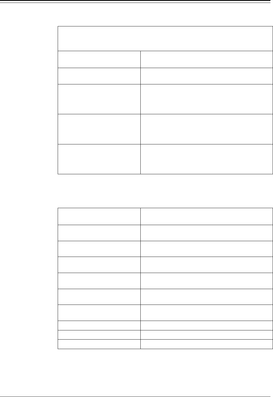
Chapter 9 Security, Service & Diagnostics Accu-Wave
9-12 TN Technologies
Factory Service & Related Items” Menu (cont.)
[Service only item]
Display Comments
signal diagnostics→→
Menu subgroup header. See “Signal diagnostics”
menu table below.
Factory test
!!! Erases ALL !!!
←←Reject command
EXECUTE CMD→→
Performs an in-depth test of the system. Test takes
several minutes to complete and erases all setup data.
View menu, special
measurement, alarm &
command codes→→
NEXT↓↓
Allows you to scroll through a list of the codes for
commands, special measurements (add offset of 1024
to measurement number), and alarms.
Do not use break tab
distance correction
Change to “Do”→→
Continue as is.↓↓
Hardware Diagnostics (Factory Service Submenu)
Display Comments
hardware status:
DSP BRD Indicates DSP board is installed.
hardware status:
relays installed Indicates relays are installed.
Soc 1 board type:
current-relay Board type installed in transmitter PCB slot #1.
Soc 2 board type:
none Board type installed in transmitter PCB slot #2.
Soc 3 board type:
DSP Board type installed in transmitter PCB slot #3.
Soc 4 board type:
none Board type installed in transmitter PCB slot #4.
current outputs = 1 Number of current outputs installed.
relays = 2 Number of relays installed.
Switch INPUTs = 2 Number of contact closure inputs installed.

Accu-Wave Chapter 9 Security, Service & Diagnostic
TN Technologies 9-13
View Error Status: Bad NV writes, etc. (Factory Service Submenu)
“View Error Status Bad NV writes, etc” Menu
Display Comments
address 00h
failed to clear
(00 is OK)
NEXT↓↓
If non-zero, address could not be erased.
address 00h
write failed verify
(00 is OK)
NEXT↓↓
If non-zero, address could not be written correctly.
address 00h
write to PROM area
(00 is OK)
NEXT↓↓
If non-zero, write to PROM address failed.
Any NV
error count 0
NEXT↓↓
Count of Non-Volatile (NV) RAM errors.
primary NV
error count 0
NEXT↓↓
Count of primary NVRAM errors.
Sec NV
error count 0
NEXT↓↓
Count of secondary NVRAM errors.
Prot RAM
error count 0
NEXT↓↓
Count of protected memory errors.
clear DSP status
history
←←Reject Command
EXECUTE CMD→→

Chapter 9 Security, Service & Diagnostics Accu-Wave
9-14 TN Technologies
Test relays (Factory Service Submenu)
Note: This submenu is not displayed if no relays are installed.
“Test Relays” (Factory Service Submenu)
[Service Only Item]
Display Comments
commands 88, 89, 153
relay to test = #1
NEXT↓↓
Enter relay number to test.
test-set relay #1
←←Exit this menu.
NEXT↓↓ EXECUTE CMD→→
Test “setting” relay 1 (activate).
test-clr relay #1
←←Exit this menu.
NEXT↓↓ EXECUTE CMD→→
Test clearing relay #1.
test all relays on
←←Exit this menu.
NEXT↓↓ EXECUTE CMD→→
Test turning all relays on.
test all relays off
←←Exit this menu.
NEXT↓↓ EXECUTE CMD→→
Test clearing all relays.
clear all holds
(none now in effect)
←←Exit this menu.
NEXT↓↓ EXECUTE CMD→→
Clear any holds in effect.
test step relay #1
←←Exit this menu.
NEXT↓↓ EXECUTE CMD→→
Press → to test closing each relay in sequence,
beginning with relay number entered in first item of
this menu.
reset IOUT FPGA
←←Exit this menu.
NEXT↓↓ EXECUTE CMD→→
Reset I/O board logic – does not reset relays.

Accu-Wave Chapter 9 Security, Service & Diagnostic
TN Technologies 9-15
Signal Diagnostics (Factory Service Submenu)
“Signal Diagnostics” Menu
[Service Only Item]
Display Comments
Do not spec to sweep
sig for scope
Change to “Do”→→
Continue as is.↓↓
Time shares the sweep control line to the head with
the frequency spectrum for use with a scope. A low
going pulse on the line is provided for scope trigger.
Do not I.F. to sweep
sig for scope
Change to “Do”→→
Continue as is.↓↓
Time shares the sweep control line to the head with
the I.F. (audio) signal date for use with a scope. A
low going pulse on the line is provided for scope
trigger.
Set gain = 0.000
(1.0 – 40, overrides
automatic value)
(1.252 in use) NEXT↓↓
Normally, the preamp gain is adjusted based on the
dielectric constant and the measurement range. This
selection disables the range determined portion of the
gain.
Dielectric constant
of process 0.000
(presently 80.00)
NEXT↓↓
If value is 0.00, the “presently” assumed value is
used. Enter a non-zero value to change default.
Dielectric constant determines gain applied to
microwave signal.
Do not disable
range-GAIN function.
Change to “Do”→→
Continue as is.↓↓
gain set step 1
set=20.00 gain=1.252
NEXT↓↓
Gain is a non-linear function of gain setting.
Select step number.
+ gain set 1 steps
set=20.00 gain=1.252
←←Reject command
EXECUTE CMD→→
- gain set 1 steps
set=20.00 gain=1.252
←←Reject command
EXECUTE CMD→→
track MIN & MAX on
measurement 0
none
NEXT↓↓ CHANGE→→
Press → to select measurement number. Selecting a
non-zero measurement number will cause additional
menu items to be displayed allowing you to track the
min and max values of the selected measurement.

Accu-Wave Appendix A Returning Equipment for Service
TN Technologies A-1
Appendix A How to Return Equipment for Service
Call the TN Technical Services Department (Factory Service division) before returning
equipment for repair. Many problems can be diagnosed and resolved over the phone. For
after hours or weekend service, call our 24-hour Service number: 512-388-9320.
With all units returned for repair, please include:
• Specific information about the problem.
• A contact name and phone number, in case we need more information.
• A purchase order authorizing repairs, or a request for a quote.
Ship prepaid to the address below:
Factory Service Department
TN Technologies
2555 North IH 35
Round Rock, Texas 78664
Our Receiving Department will not accept collect shipments.
Do not ship to our P.O. Box.

Accu-Wave Appendix B Specifications
TN Technologies B-1
Appendix B Specifications
Operating Principle
Frequency modulated continuous wave (FMCW)
radar signal which measures distance;
microprocessor based transmitter computes level,
volume and nine other measurements.
Range
Up to 115 ft. (35 m.)
Reference Accuracy
±3 mm (1/8 in.)
Repeatability
±3 mm (1/8 in.)
Input Power
24 Vdc ±25%, 12 W
Serial Outputs & Inputs
RS-485 (Standard): Half duplex partyline
communication to a host computer or hand-held
terminal.
RS-232 (Optional): Full duplex communication with
a remote terminal, printer, PC or host computer.
Current Output
4 to 20 mA, isolated, loop-powered (24 Vdc).
Maximum load – 700 ohms. Compliant with
NAMUR 43 specification for fault current.
Contact Closure Input
1 contact closure input provided. (User provides
switch.)
Circuit Protection
Meets IEC 801-1,-2, and –3
Current output is isolated.
Microwave Emissions
In compliance with ANSI C95.1, “RF Field
Exposure Safety Guidelines”
Dimensions
Refer to Dimensional Drawings
Rod Antenna: D868217
Horn Antenna: TBD
Weight
Rod Antenna: ~15 lbs.
Horn Antenna: TBD.
Temperature Range (Electronics)
-40o C to +70oC (-40o F to +158o F)
Pressure
Rod Antenna
PP 600 psig. max.
PTFE 300 psig. max.
Exposed Materials (Process)
Rod Antenna
SS316 and Polypropylene, or
SS316, PTFE, and O-ring material.
Horn Antenna
TBD
Mounting
Rod Antenna
1 inch NPT bushing, or
Welded flange (150/300 lb.; 2, 3, 4, 6 inch )
Horn Antenna
TBD
Hazardous Location Approvals
FM
Class I, II, III, Division 1, Groups B, C, D, E, F, G
Class I, II, III, Division 2, Groups B, C, D, F, G
NEMA 4X
CSA
Class I, II, III, Division 1, Groups B, C, D, E, F, G
Class I, II, III, Division 2, Groups B, C, D, E, F, G
TYPE 4X
CENELEC
EEx d IIB + H2
Eex n IIB + H2
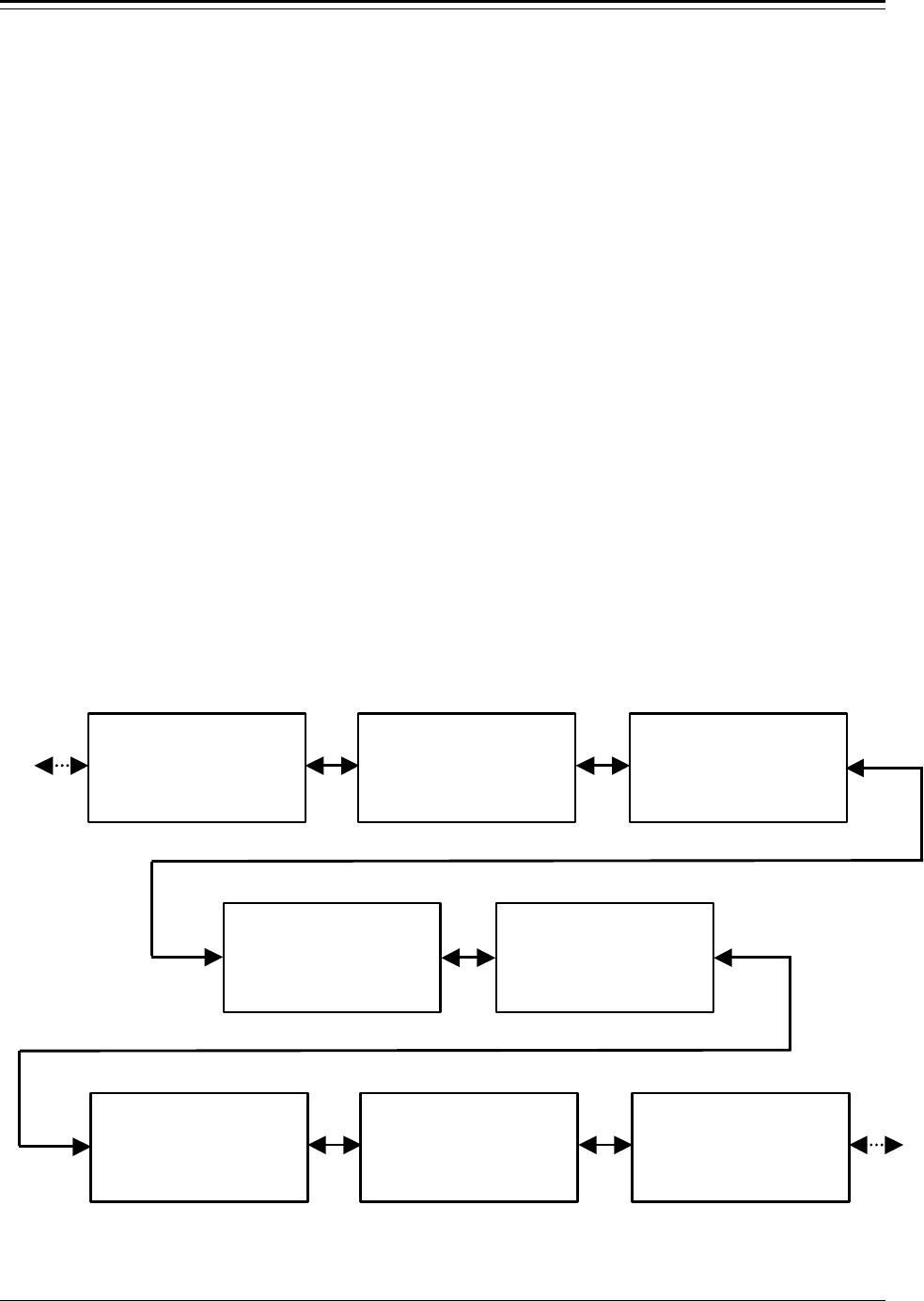
Accu-Wave Appendix C Menu Flowcharts
TN Technologies C-1
Appendix C Menu Flowcharts
This appendix shows the overall arrangement of the menu groups and the menus contained
in each menu group. Use the arrow keys to scroll through the menus. Help texts are
available at appropriate points. The dynamic menu system controls the items you see so
that only menu selections pertinent to your application are presented.
Note: The actual menu display can vary dynamically with context. Many menus,
items, or selections appear only if the proper conditions are met. For
instance, current-output related items do not appear if a current I/O board
is not installed.
Most items will show a somewhat different message when accessed by
direct entry than when seen in the setup menus.
When no entries are made in the setup menus for five minutes, the display times out and
returns to the measurement display shown in Figure 2.1. Any changes you made are saved
and used by the gauge. See Chapter 2 for a more detailed explanation of how to use the
menus.
The diagram below shows an overview of the top-level menu groups. Some items are not
always displayed, depending on your application and previous settings. The tables on the
following pages explain prerequisite conditions for each conditional menu. The tables also
reference the sections / page numbers that describe each menu. Refer to those sections for
information about individual setup items and lower-level menus.
Set up level, level
alarms, & volume
←←Exit Setup.
Other functions→→
Set up additional
measurement
(readouts).
Other functions→→
Radar fine tuning,
(not required in
most applications)↓↓
Other functions→→
Modify or re-assign
current output.↓↓
Other functions→→
Set up fault alarms
or change process
assignments.↓↓
Other functions→→
Action items: (Erase
memory, Clear alarms
Hold output, etc)↓↓
Other functions→→
Set up serial ports
contact INPUT, or
special functions↓↓
Other functions→→
Security, service
and diagnostic
functions.↓↓
Other functions →→

Appendix C Menu Flowcharts Accu-Wave
C-2 TN Technologies
Top Level Menu Structure
This table describes the top-level menus and references the appropriate chapter in the
manual. Each of these menus is then described in a separate table on the following pages.
Top Level Menu Structure
Display Comments
Set up level, level
alarms, & volume
←←Exit Setup.
Other functions→→
See Chapter 3. Primary measurement setup – distance
or level. Set up alarm(s) (optional) for the primary
measurement and set up tank volume (optional).
Set up additional
measurement
(readouts).
Other functions→→
See Chapter 4. Define and set up additional
measurement readouts. All alarms are assigned to
primary measurement by default. To set up an alarm
for a “non-primary” measurement, you must first
assign an alarm to the measurement using the “Set up
fault alarms…” menu below.
Radar fine tuning,
(not required in
most applications)↓↓
Other functions→→
See Chapter 5. Various tools for fine tuning the radar
gauge. Often these tools are not required except in
more difficult applications – such as tanks where
other structures cause false echoes, where agitator
blades cause problems in locking onto the proper
echo, or for low dielectric constant process materials.
Modify or re-assign
current output.↓↓
Other functions→→
See Chapter 1. Current output related menu items.
Only displayed if an I/O board with a current output
is installed in the Accu-Wave transmitter.
Set up fault alarms
or change process
assignments.↓↓
Other functions→→
See Chapter 1. Assign process (measurement) alarms
and set up other types (fault, warning, or mode)
alarms. This menu is not displayed unless relays are
installed, or unless you “enable alarm-related
functions” under the “Special Functions” menu (see
page 8-19).
Action items: (Erase
memory, Clear alarms
Hold output, etc)↓↓
Other functions→→
See Chapter 7. Set up and/or execute various action
items.
Set up serial ports
contact INPUT, or
special functions↓↓
Other functions→→
See Chapter 8. Configure the serial ports, the contact
closure inputs, and a number of miscellaneous
“special” functions.
Security, service
and diagnostic
functions.↓↓
Other functions →→
See Chapter 9. As the menu title states, security,
service, and diagnostic functions and tools are
provided.

Accu-Wave Appendix C Menu Flowcharts
TN Technologies C-3
“Set Up Level, Level Alarms, & Volume” Menu Group
“Set Up Level, Level Alarms, & Volume” Menu
Display Comments
(primary measurement
setup items) Page 3-2. Set up the primary measurement.
(current output span /
display scaling) Page 3-2. Set up the current output span relative to
the primmary measurement. Only displayed if I/O
board w/current output is installed.
Set up alarm 1
(alarm 2,etc)→→
Page 3-6. Set up alarm(s) for primary measurement.
Only displayed if relays are installed or if alarm-
related selections are enabled in “Special functions”
menu. Menus displayed for alarms 2–16, as needed.
Tank volume setup→→ Page 3-13. Set up volume measurement (optional).
“Set Up Additional Measurements” Menu Group
“Set Up Additional Measurements” Menu
Display Comments
Modify setup of
measurement 1
(units) →→
Page 3-2. Modify setup of primary measurement.
Only displayed if service-only items are enabled in
the “Special functions” menu.
Assign & setup or
Modify setup of
measurement (number)
(units) →→
Page 4-1. Set up or modify previously setup
additional measurements.
(measurement type and
units items) Page 4-2. Define parameters for next measurement to
be set up (measurement number 2 to 8).
(measurement display
items) Page 4-6. Parameters related to measurement readout
display.
Set up alarm n →→ Page 4-9. Set up alarm(s) for additional
measurements. Alarms must first be assigned to
measurement (see page 6-3).

Appendix C Menu Flowcharts Accu-Wave
C-4 TN Technologies
“Radar Fine Tuning” Menu Group
“Radar Fine Tuning” Menu
Display Comments
material type and
measurement head
setup→→
Page 5-2.
modify range of
measurement→→
Page 5-4.
Response time, lost
echo and agitator
reject setup→→
Page 5-6.
False echo
management→→
Page 5-11. Includes several submenus for specialied
tools false echo management:
Clutter Management, page 5-17,
Tank Map Setup, page 5-21,
Region Weighting Setup, page 5-24,
Dynamic Threshold Setup, page 5-26.
The last three tool menus are only displayed of the
“service only items” are enabled.
“Modify or Reassign Current Output” Menu Group
“Modify or Reassign Current Output” Menu
Display Comments
(Current output range
items) Page 6-1. Set max/min current output values.
(Measurement
assignment items) Page 6-1. Assign measurement to each installed
current output in normal and alternate modes.
(Correction factor
items) Page 6-1. Allows fine tuning of current output values.
(Current HOLD value
setting) Page 6-1. Specify current output hold values.

Accu-Wave Appendix C Menu Flowcharts
TN Technologies C-5
“Set up Fault Alarms or Change Process Alarm Assignments” Menu Group
“Set up Fault Alarms or Change Process Alarm Assignments” Menu
Display Comments
Set up for alarms to
execute commands →→
Page 6-4.
Assign alarms to
measurements →→
Page 6-5. Available only if additional measurements
are set up. Alarms must be assigned to non-primary
measurements using this item, before alarms can be
set up for “non-primary” measurements.
Assign “relays” to
warning alarms and
fault alarms →→
Page 6-6.
Assign “relays” to
mode alarms →→
Page 6-8.
(“show relay status”
selection item) Page 6-3.
“Action Items Menu” Group
Contains the most frequently used commands grouped in four submenus.
“Action Items Menu”
Display Comments
Common action items
(clear memory, etc)→→
Page 7-2.
Alarm action items
(View, clear, etc)→→
Page 7-3. Displayed only if relays are installed or if
alarm-related selections are enabled in the “special
functions” menu.
“Hold” action items
(Hold reading, etc)→→
Page 7-4.
Serial port related
action items →→
Page 7-6.
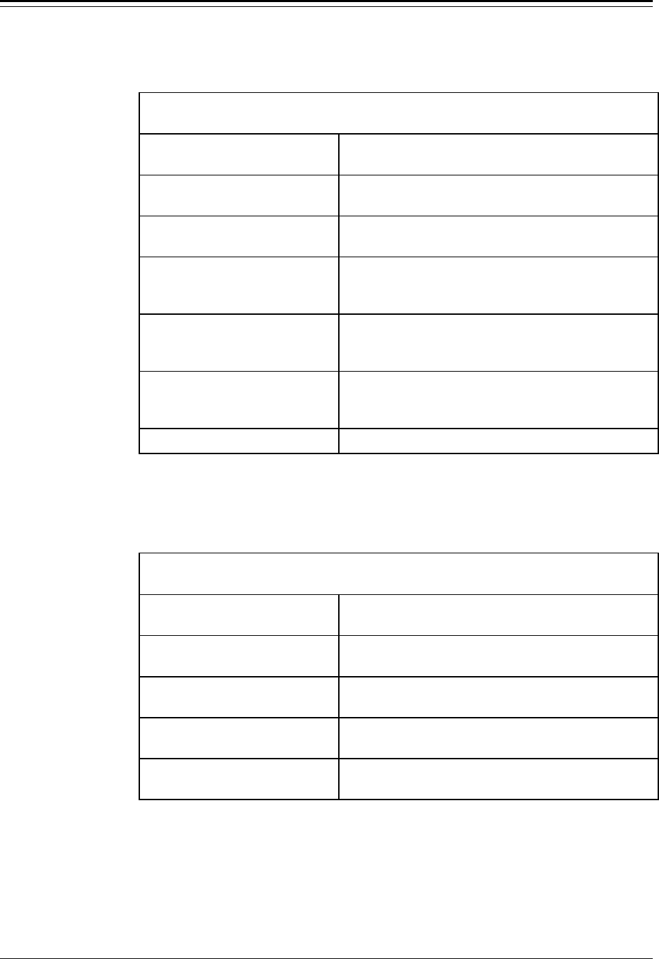
Appendix C Menu Flowcharts Accu-Wave
C-6 TN Technologies
“Set Up Serial Ports, Contact Input, or Special Functions” Menu Group
“Set Up Serial Ports, Contact Input, or Special Functions” Menu
Display Comments
Modify port 1 RS232
configuration →→
Page 8-8.
Modify port 2 RS485
configuration →→
Page 8-8.
Set up port 1 RS232
data transmission →→
(data streaming)
Page 8-10.
Set up port 2 RS485
data transmission →→
(data streaming)
Page 8-10.
Assign commands to
execute on contact
open/close 1 (2)→→
Page 8-18. Available only if a relay I/O board (with
or without relays) is installed.
Special Functions →→ Page 8-19.
“Security, Service, and Diagnostic Functions” Menu Group
“Security, Service, and Diagnostic Functions” Menu
Display Comments
Security items:
(password, etc.) →→
Page 9-1.
Diagnostics: system
test, related items →→
Page 9-2.
User service
& related items →→
Page 9-9.
Factory service
& related items →→
Page 9-11. Available only if service-only items are
enabled in “Special functions” menu.

Accu-Wave Appendix C Menu Flowcharts
TN Technologies 1
Glossary
• AC Alternating
current.
• Alarm In this manual,
does not necessarily mean
an abnormal or dangerous
condition exists. Here
alarm broadly means that
a previously specified
condition exists. Alarms
can be process, system
fault and warning.
• Alarm clear
Condition under which
the alarm ceases.
• Alarm clear point
Measurement at which
alarm is deactivated or
cleared.
• Alarm set point
Level (or distance,
volume) at which alarm is
triggered. When
triggered, user defined
alarm action occurs. This
can be any of several
things such as flash
display, activate relay, or
execute command.
• ALM Alarm.
• ALM CLR Alarm
clear.
• ALM SET Alarm
set.
• Antenna Bottom of sensor.
A device for sending or
receiving radio waves.
• Antenna offset
Another name for zero
distance point.
• Assign To link or
connect. For example, you
can “assign” the level
measurement to an alarm.
Then you can assign an
“output” such as flash
display or execute
command for that alarm.
The end result is that a
level at or above the level
you specify will cause the
display to flash or will
execute a command.
• Assy. Assembly.
• Attenuate To
reduce. For example, to
reduce the intensity of
microwaves by passing
them through an
absorbing medium.
• Baffle A device such as
a plate or wall used to
deflect, check or regulate
flow.
• Baud rate
Any of the standard
transmission rates for
sending or receiving
binary coded data.

Glossary Accu-Wave
Glossary-2 TN Technologies
•
• Beamwidth Out
going microwaves spread
out approximately 15⋅
wide.
• Board A flat sheet on
which integrated circuits
are printed.
• Break point table
A table of 1-16 points
(distance or level) and the
corresponding volume of
the tank at that point.
• Cal Calibration.
• Cap Top of sensor.
Contains transceiver and
preamp assembly.
• Clear point The
reading at which the
alarm ceases.
• Clutter Clutter is one or
more false echoes from
the following: the sensor
itself, the isolation seal (if
present), or the tank
nozzle.
• Clutter distance
Defines the distance out
from the reference line
over which the gauge
should cancel the clutter
signal.
• CMD Command.
• Coaxial cable
Cable with a center
conductor surrounded by a
dielectric sheath and an
external conductor. Has
controlled impedance
characteristics that make
it valuable for data
transmission.
• COMM module
Communication module
for serial communications
with the gauge.
• Command code
A numeric code used in
direct entry to cause the
transmitter to execute a
command from the
keyboard instead of from
the menus.
• Compound shapes
Can be described as two
or more of the predefined
shapes.
• CPU Central
processing unit.
• Dead band The
range of readings between
the set and clear points.
• Decimal Point Position
Specifies the position of
the decimal point in the
measurement readout, for
example, 12.34 or 123.4.
• Dielectric A
nonconductor of direct
electrical current.
• Dielectric constant
Determine a material’s
ability to reflect
microwaves.
• Direct entry Use
keypad to directly access a
menu item or execute a
command without
scrolling through the
menus.
• Display mode
The gauge display is in
“normal” mode when it is
first turned on. It can be
set up to display normal
mode or alternate mode or
to toggle between the two.
• DSP Digital signal
processing
• DPT Dynamic process
tracking
• Echo Return
microwave signal.
• Echo #1 The echo that
appears to be reflected
from the farthest object.
• Echo qualification
When more than one echo
is received, the gauge uses
this process to determine
which one is reflected
from the process material.

Accu-Wave Glossary
TN Technologies Glossary-3
• Entry ID
Identifies a menu
item for direct entry.
• Esters Any of a class of
often fragrant compounds
that can be represented by
the formula RCOOR’ and
that are usually formed by
the reaction between an
acid and an alcohol with
elimination of water. For
example: acetate.
• False echo Echo
reflected from any surface
other than the surface of
the process material. For
example, echoes reflected
off of baffle support
brackets or the bottom of
the tank.
• False signal
Any signal (echo)
reflected from any surface
other than the surface of
the process material. For
example, microwaves
reflected off of baffle
support brackets or the
bottom of the tank.
• Fault A hardware or
software condition that
causes a device, a
component, or an element
to fail to perform in a
required manner
• Fault alarm Notifies
you of level signal lost or
system fault (others are
also available). A line on
the display flashes off and
on.
• GA Gauge, thickness
of wire.
• Gauge Combined sensor
and transmitter.
• Good echo Values
are inside the signal
window.
• HELP Information in
the menu to explain a
particular item.
• HEX Hexadecimal.
• Hidden keys
Unmarked keys located
around the keypad on the
transmitter which can be
programmed by the user.
Also called blank keys.
• High alarm The
clear point is less than the
set point.
• Hz Hertz (cycles per
second)
• I/O Input and output
• Intrusive mounting
The antenna extends
downward into the tank
nozzle.
• Isolation mounting
The antenna is mounted
outside the tank and
separated from the process
material by a seal.
• Item identifier
Identifies an item for
direct entry.
• Keyboard code
A menu item identifier
used in direct entry.
• Keypad Used to enter
commands and data and
to scroll through items,
options and menus.
• Linearity The
closeness to which a curve
approximates a straight
line.
• Lost signal alarm
For some reason, the
sensor is not detecting a
strong enough microwave
reflection to make a
measurement. Minimum
acceptable signal strength
and action to take if the
signal is lost are
programmed by the
customer.
• Low alarm The
clear point is greater than
the set point.
• Marker Indicates an
event.

Glossary Accu-Wave
Glossary-4 TN Technologies
• MAXECHOS
Maximum number of
echoes to be processed.
• Meas. To measure or a
measurement.
• Measurement
Any parameter which the
gauge is programmed to
measure or display. For
example, level, distance,
or volume.
• Measurement #1
The primary
measurement, either
distance or level.
• Measurement display
Shows the current values
of distance or level, signal
strength, and other
measurements that have
been set up.
• Measurement head
The sensor.
• Measurement head
geometry
Whether the sensor is an
isolation mounting or
intrusive mounting type.
• NEC National Electric
Code
• Outage Distance from
top of tank to material
surface.
• Password Provides
security.
• PC Personal
computer.
• PF Preference factor.
• Predefined shapes
The gauge can calculate
the volume of the
following shapes: vertical
cylinder, vertical
rectangle, vertical cone,
horizontal cylinder with
flat ends, horizontal
cylinder with domed ends,
sphere, sloped bottom
cylinder, and parabola.
• Primary measurement
Either distance or level.
Also referred to as
measurement 1. Limited
to level or distance. See
“Set up level, ...” menu.
• Process alarm
High and low alarms. Set
point (trigger point) and
clear point are entered on
the “Set up Level” menu.
• Process material
Material, usually liquid,
whose level is being
measured.
• Program In this manual,
means using the menus to
define the measurements
and alarms.
• Radar Detects distant
objects by means of radio
waves reflected from an
object; the term is derived
from the original term
radio detection and
ranging.
• Radar fine tuning
This menu is used
customize set up for
challenging applications.
Here you can enter a
specific dielectric constant
(standard level setup only
requires that you specify
water or non-water based
liquid material). Clutter
distance, auto clutter
update time, agitator
reject time, etc. are also
on this menu.
• Readouts
Measured
parameters which have
been set up to display on
the gauge screen.
• REF LINE
Reference line
that is cast in the antenna
housing.
• Reflected wave
The portion of the
microwave reflected from

Accu-Wave Glossary
TN Technologies Glossary-5
the process material back
to the gauge sensor.
• Refracted wave
Only of concern when the
process material has a low
dielectric and the material
level in vessel is also low.
Wave train produced
when microwaves cross
boundary between 2
media (for example, air
and process material).
Refracted portion of wave
is that which crosses into
second medium and is not
reflected back to sensor.
• Relay A switch used to
activate the contact
outputs when an alarm
occurs.
• ROI Range of interest.
• EXIT SETUP key
Saves your entries and
returns to the
measurement display.
• Scientific notation
A floating-point system in
which numbers are
expressed as a product of
a number between 1 and
9.999 multiplied by an
appropriate power of 10
(3.465E-4).
• Sensor Contains the
microwave circuitry.
Includes transceiver and
preamp assembly,
antenna, adapter flange,
seals and gaskets.
• Serial port
Accommodates
serial data transmission,
that is, each bit is sent
sequentially (one bit at a
time).
• Set point The
reading at which the
alarm occurs.
• Set up Verb: To
“program” the gauge for
your specific application.
For example, “set up
process alarms.”
• Setup Noun: As in
“level setup.” A type of
configuration, defined by
the customer. An
arrangement of data or
devices to solve a
particular problem.
• Sig Str Signal strength.
• Signal strength
Represents the amplitude
of the signal received by
the sensor. This parameter
appears when you first
power up the gauge. If you
want to use it as a “real”
system parameter, use the
“Set up Additional
Measurements” menu.
There are no units
associated with signal
strength. Minimum
acceptable signal strength
is sometimes used to fine
tune a challenging
application.
• Sparge
To agitate a liquid by
spraying compressed air
or gas through a pipe into
the liquid. Can cause
foamy surface.
• Time constant
Sets the signal filter
damping. A longer time
constant will smooth the
output, reducing the
effects of turbulence. The
default is 4 seconds.
• Toggle Verb: To switch
between 2 selections by
pressing a key. First time,
selection A appears,
second time, selection B,
third time, selection A
again.
• Transceiver
Combination of receiving
and transmitting
equipment located in the
sensor.

Glossary Accu-Wave
Glossary-6 TN Technologies
• Transmitter Does
digital processing.
• Ullage Empty volume.
• Units mask Defines
which set of measurement
units will be displayed.
The default is All.
• Volume Amount of
process material measured
in the vessel. Gauge
measures distance,
calculates the level, and
converts this to volume
based upon the vessel
shape you selected in “Set
up volume menu.”
• Vortices Whirlpools of
flowing fluid. Areas of
lower pressure with fluid
flowing in a circular
motion.
• Warning alarm
These alarms notify you of
system status; for
example, keypad in use.
• WF Weighting factor.
• Zero distance point
The vertical location on
the tank that the user
defines as zero for the
distance reading.
Frequently, top of the
tank.
• Zero level Point in
tank at which the gauge
should report level equal
to zero.
• Zero output 1 Sends
current output to 0 mA.
•